IIIIIIIII~ ~~~ II~~:~~~I ~~J:~!!I!I!~:I:~~1~~I:~
17
(12) Sou rce of Acq ui sition NASA Washington, D. C. United States Pat ent Hood (54) '1ET lIOD OF :\-IAKING AN D USI"I(; S lI .\ PE "U:"IORY POLYMlm COMPOSITE P,\ T(, II ES (75) Inventor: Patrick./. lIood_ Ikllb mok . O il (U S) (7 3) .\ ssi8nee: ('nmcrsl.onc Grnup , In c_ . Dayton , 0 11 (US) ( *) No ti ec: S ubject tn ,IllY disdaimc r. the krlll ll i' l hi s patcnl is extended or adju st ed untler 35 U.S.c. 154(b) by 54R days. (21) :\ppl. No .: 111569,902 (22) peT Filed: ./ u n.6,2005 (86) PCTNll .: PCT/US2 005/0 19842 * 371 (c )( I ). (2) . (4) LJate: S<'p.8,2008 (87) l'eT Pu b. No .: W02()06 /()46974 PCT Pub. Date: May 4,2006 (65) (GO) (5 1) (52) (58) Prior Publication Data US2008/03 1 4510A I Dec. 25, 2008 Related U.S . Applicat ion Data Provisional ap plication No. 60/ 577.003. filed on Jun . 4 .2004. Int.C!, B29C 65/ 00 B29C 73/00 U.S.C!. (200 6. 01 ) (2006 .01 ) 156/94: 156/ 95; 15 6/ 304 . 1; 156/ 304.2 ; 15 6/ 304 .3: 138/97; 138/98 ; 13 8/99 Field nf Classification Search .................... 156/94, 156/ 95.304. 1. 304 .2 .304 .3. 1 02. 106; 138/97, 138/98 . 99 See appli ca ti o n file for com plete search history. ----_._---- . ---- - --- u 'fu (4 5) Date of Patent: May 10 ,20 11 (5(,) Ih·ferellccs ( ·ited II.S. 1 >' \'1' 1 ' NT I )O('l IMI ' NTS - J.(i75.()(i I ,\ (i Me'ad -1. ()5 1l .25S .\ R· 1990 K<lWl, i d <II. 5.040.283 1\ • R 199 1 Pclg.rom ............. 21) ,-147 S.. ,xx.61 7 .\ 21 1 NS Sasak i ct al. ).XO'I.27(i ,\ I) 1998 Jacobs et al. 6.() X3 .442 1\ 72000 Gabi ll y Cl. IClO.OX4 ,\ . 1 22000 Lang.er cl al. ....... 528272 111 S 2002 r anger ct a l. 6.759.48 1 132 7200-1 Tong 6.i)X6.X55 131 I 2006 Hood et al. 20() 2 0 I 17864 Al \)2002 rong FO REIGN PATENT DOCUMENTS EP 049R602 A 8 1992 .lP 2-240487 • <) 1990 ,/1' 02 -289344 A II 1990 .I P 03-033595 A 2/ 1991 .l P 03092331 • 41199 1 .lP OJ096785 • 4 1 99 1 .II' 062 133S7 • .lP 2000-226443 • 8, 2000 WO WO 96, 12588 5. 1996 WO WOO l 64387 7/ 2001 * (; iled by examine r Prilllary Exa lllin<: r - Ju stin Fische r (57) ABSTRACT A method or repairing a composite compone nt having a dam- aged area including: layi ng a compos ite patch over Ihe dam- aged area: ac livating Ihe s hape memory polymer res in to eas il y and 4uid;J y mold said patch to sa id d:un age<.i area; dcacliva ting said sha pe memory polymer so Ihat sa id com- posite pa tch retains the mold ed sha pe ; a nd bonding said COIll- pos ite pa tc h to sa id damaged part. 67 Claims , 7 Drawing S heds 2 4
Transcript of IIIIIIIII~ ~~~ II~~:~~~I ~~J:~!!I!I!~:I:~~1~~I:~
(12)
Sou rce of Acq uisition NASA Washington , D. C.
United States Patent Hood
(54 ) '1ETlI O D OF :\-IAKING AN D USI"I(; SlI .\ PE "U:"IORY POLYMlm COMPOSITE P,\T(, II ES
(75) Inventor: Patrick./. lIood _ Ikllb mok . O il (U S)
(73) .\ ss i8nee: ('nmcrsl.onc Rcscar~h Grnup, Inc_ . Dayton , 0 11 (US)
( *) No tiec: Subjec t tn ,IllY disdaimcr. the krlll ll i' lhi s patcnl is extended o r adjusted untler 35 U.S.c. 154(b) by 54R days.
(2 1 ) :\ppl. No .: 111569,902
(22) peT Filed : ./ u n.6,2005
(86) PCTNll .: PCT/US2 005/0 19842
* 37 1 (c )( I ). (2) . (4) LJa te : S<'p.8,2008
(87) l'eT Pub. No .: W02()06/()46974
PCT Pub. Date: May 4,2006
(65)
(GO)
(5 1 )
(52)
(58)
Prior Publication Data
US2008/03 14510A I Dec. 25, 2008
Related U.S . Application Data
Provisiona l applicat ion No. 60/577.003. filed on Jun . 4 .2004 .
Int.C!, B29C 65/ 00 B29C 73/00 U.S.C!.
(200 6.01 ) (200 6.01 )
156/94 : 156/95; 156/304. 1; 156/304.2 ; 156/ 304.3: 138/97; 138/98; 138/99
Field nf C lassification Search .................... 156/94, 156/95.304. 1. 304 .2 .304 .3. 102. 106; 138/97,
138/98 . 99 See application file for complete search history.
----_._---- .----- ---
IIIIIIIII~~ ~~~ II~~:~~~I ~~J:~!!I!I!~:I:~~1~~I:~ u 'fu
(4 5) Date of Patent: May 10,2011
(5(,) Ih·ferellccs ( ·ited
II.S . 1>' \'1' 1 ' NT I )O('l IMI ' NTS
-J.(i75.()(i I ,\ (i 1 1)~7 Me'ad -1.()51l .25S .\ R· 1990 K<lWl, i d <II. 5.040.283 1\ • R 199 1 Pclg.rom ............. 21),-147 S .. ,xx.61 7 . \ 2 11NS Sasak i ct al. ).XO'I.27(i ,\ I) 1998 Jacobs et al. 6.() X3 .442 1\ 72000 Gabi lly Cl. IClO.OX4 ,\ . 122000 Lang.er cl al. ....... 528272 6.~8S.()43 111 S 2002 r anger ct a l. 6.759.48 1 132 7200-1 Tong 6.i)X6.X55 131 I 2006 Hood et al.
20()2 0 I 17864 A l \)2002 rong
FOREIGN PATENT DOCUMENTS
EP 049R602 A 8 1992 .lP 2-240487 • <) 1990 ,/1' 02-289344 A II 1990 .I P 03-033595 A 2/ 1991 .l P 03092331 • 41199 1 .lP OJ096785 • 4 199 1 .II' 062 133S7 • ~. 1 !)!)4
.lP 2000-226443 • 8,2000 WO WO 96, 12588 5. 1996 WO WOO l 64387 7/2001
* (; iled by examiner
Prilllary Exalllin<:r - Justin Fischer
(57) ABSTRACT
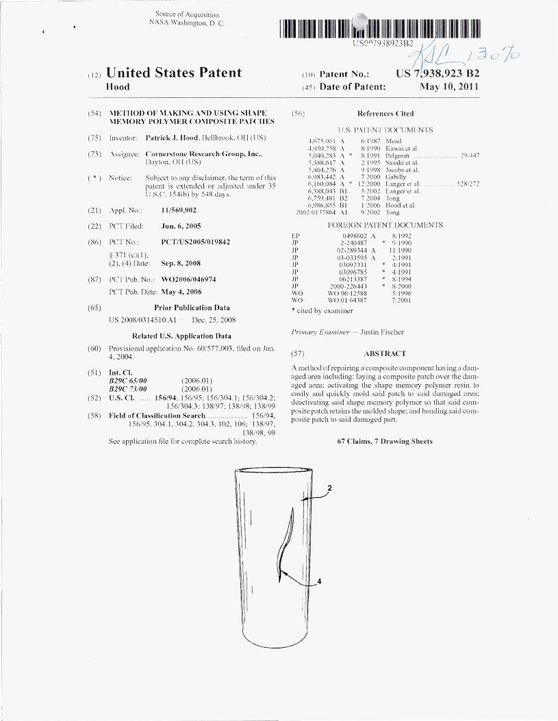
A method o r repairing a composite component having a damaged area including: laying a composite patch over Ihe damaged area: acliva ting Ihe shape memory polymer resin to eas ily and 4uid;Jy mold said patch to sa id d:un age<.i area; dcacliva ting said shape memory polymer so Ihat sa id composi te patch retains the mo lded shape; a nd bonding said COIll
pos ite pa tc h to sa id damaged part.
67 Claims, 7 Drawing Sheds
2
4

U.S. Patent May 10, 2011 Sheet I of 7 US 7,938.923 B2
2
2
\ .
8
4 .
Fig.1 Fig.3
Fig.2
-- -------
i
U.S. Patent May 10, 2011 Sneer 2 of 7 US 7,938,923 B2
Fig.4
rig. o
u.s. Patent May l0 , 2011 Sheet 3 of 7 US 7,938,923 82
16
22 ~o
'I
Fig. 6
Fig.7
26
Fig. 8

U.S. Patent May 10, 201 J Sheet 4 of 7 US 7,938,923 82
Fig. 9
Fig. 10
.... - .- - ._ .. _----- .. - -------- ._. -_ .. _-- --._. ----~-.-
u.s. Patent May 10, 2011 Sheet 5 of 7 US 7,938,923 B2
34 Fig. 11
Fig. 12
Fig. 13
U.S. Patent M ay 10, 20 11 Sheet 6 of 7 US 7,938,923 82
44 \. \~ 7
34 Fig. 14
Fig. 15
u.s. Patent Mayl0,2011 Sheet 7 of 7 lJS 7,938,923 82
.Fig.16
Fig.17

US 7,93 8,923 82
\11('1'1101) OF M . \KI~G .\ NI) l' SI~G SII .\PE \IE,VIORY I'OLV;VU:R COMPOSITE PATCIlES
( ' IH )SS- I{I ·Y I :I{"NC'I ~ TO RI':I ,, \1'1 ':1 ) .\ I'I'I.lCATION
Priority benefit of U. S. PrnvisionalPatent l\prl ication Ser. No. 60/577.003 liled Jun. 4. 2004 is daimed.
STATEMENT REGARDING FEDERALLY SPONSORED RESE.I\RCH
'nlis applica tion was made in part with goverIunent support under con tract nUlllber NNK050A 21)(' awarded by the National Aeronaut ics and Spact: Administrat io n. T ht: govemmt:nt has certain lights in the invention.
I1ACKCiROUND OF TH E INVENTION
'nle present invention genemlly rela tes to the repair of components made from nwterial stleh as metals. compos ites. wood, plastics. glass and other materia ls. It is to be appreciated that the present invention has genera l and specitic industri a l app lication in the repa ir of va rious materi als. The term "composite" is commonly used in indust ry to identify components produced by impregnat ing a lib rous materia l wi th a thermop lastic or thermosetting resin to form laminates or layers.
Genern lly, polymers and po lymer composite have the advantagt:s ofwcight sav ing, higb specilic mecbanica l properties, and good corrosion res istance which make them indispens<tblt: matt:ria ls in all are<ts uf manul~lcturi.ng. Nt:vertheless , manufacturing custs are somt:time detrimental. s ince they can represent a considerable part of the total costs and are made even more costly by the inab ility to quickly and eas ily repair these materi al w ithout requiring a complete, and expensivt:. total rt:placeme nt. Fu rthe rmore, the production o f com plex shaped part s is s till a cha lle nge for the composi te industry. The limitt!d putt:nt ial fo r complt:x shape running or!ered by advanced composite matt:ria ls leaves little scope for des ign freedom in order to improve mechanica l perlll rmanee and/o r integrate supplementary fu nctions. This has bee n one o f the prinw ry limi tatio ns for a wider use o r advanced composites in cost-sensitive large volWlle applicatio ns . ,\ dd itionall y. the nature of composite materials docs nut It:nd i tsei r to easy repa ir. espt.'Cia ll y un l:ht:ap, mass produced items a nd repair kits fo r mo re expensive. specia lty ite ms (such as in the aeronilu ti c industry ) are bulk")'. expensive, and require long time to complett: the repa ir.
Sha pe memory po lymers (S MPs) and shape memory a ll oys (SMAs) were first developed about 20 years ago and Iwve been the subject of conuncrc ia l development in the last 10 yea rs. SMPs are polymers that derive their name from thei r inherent ability to return to their original "memo ri7ed" shnpe ;1 Iter undergoing iI shape deIlmlwtion. SMPs that have been prelormed can be ddormed to any desired shape below or above it s glass transition temperJ tllre cr.). If it is be low the T,.' this process is ca ll ed cold de to rmation. When de illflnatio n o ftht! SMP occurs above it s Tg . the process is denoted as warm deformiltion . In ei ther case the SMP must remain bel ow. o r be ljuenched to below. the Ts wh ile m(linwined in the des ired dcJi,)rIlled sha pe to "Inck" in the (kl ll fl1l (ltion. O nce tht: dclo l'lna tio n is Incked in. Ihe po lymer netloV l) rk C(lll
nnt r.:ll1rt1 to a rdax.:d state uue 10 thermal barriers. The s\t!r \~i II hold its delilfll ll.'<l sh; lre indefinitely ulltil it is hea ted above its T •. wherea t the S 11' stored mechanical str<li n i: reiea,ed and the SMP returns to it s per tllfllled sta te .
2 SMl's are not simply elastomers. nor simply pbstics . They
l'x hibi t ch;lr;lcteristics of bot h materials. depending on their tcmperature . While rigid. (In SMI' demo ns lrates the s trengthtn-weight ratio o f a rigid polymer: ho\~ever. nurmal rigid pnlymers under therma l stimulus simply Ilnw or melt into a r(ll1d1l 111 new share. and they have no "ll1ell1ori/.ed" shape to which they can return. While hea ted and pli;lbk. an SMP has the Ilexibility of a high-qua lity. dynamic elastomer. tolerating up to -100% elongation o r more; however. unlike normal elas-
III tOllle rs. an SM I' cil n he reshaped or returned quick ly to its memori zed shape and subsequently cooled into a rigid p lastic.
Sevt:r<d knnwn polymer types exhibit shape memory propert ies. Probab ly the best known and best resea rchL'<I polymer
15 types exhibiting Sh(lpe memory polymer properties are polyure thane polymers . Gordon, Proc uf' Firsl Inli. COI7/.' Shape Memo':!' and Supere/a slic 'Iech .. 11 5-120 ( 11)<)4 ) and 'I()bushi l;!t a I., Proc o/Firsl [nil. Con(' Shape Memorr lind Supere laslie Tech .. t 09-1 14 ( 1994) exemplify studies direclL'd to prop-
211 erties ;md application of shape memory polymethalles. . \ not her po lymeric system based on crosslinking polye thylene homopolymer wns reported by S. Ota, Radiat. Phys. Clielll . 18, 8 1 ( 198 1). A styrene-butndiene thermoplastic copolymer system was also described by Japan Kokai, JP
25 63-179955 to exhibit shape memory properties . Polyisoprelle was ;1 Iso c laimed to exhibit sbape memory properties in Japan Koka i JP 62-192440. A.nother known polymeric system, uisclosed by Kagami et aI. , Macromol. Rapid Commllnication, 17. 539-543 (J 996), is tbe class of copo lymers of stearyl
30 acrylate and acry lic acid or methyl acrylate. Other SM P polymers known in the art include articles formed of norbomene ur dimet haJ)t:\.lct~hydronapthalene humupolYJl1t!rs or copolymers , se t forth in U.S. Pat. No . 4.83 1,094. Add itionally, styrene copo lymer based SMPs are disclosed in U.S. Pat. No.
35 6.759,48 1 which is incorporated herein hy reference. Modem ai rc ra ft are perhaps one of the largest users 01'
compo site materia ls. Composites a re widely used in the aerospace industry to provide aircraft components such as fuselages . wings and tail fins, duors and so on. This is because
40 composite components have the physical anribute of being relatively li ghtweight while at the S,:Ulle time having high stnIctural strength in comparison to meta ls. Such composite components typica ll y il re of a sandwich constnIctio n. When damage occurs to such stnIctures. for example by impacted
45 damage rrom a ilying sto ne or othcr debris or from a dropped tou l. a damagt: cr<lter, crack, or holt! \~ill be rormeu in the object concemed.
The general ilpproach to repair damage is to remuve tbe damaged pan from the aircraft. and repa ir the damage by
,0 using a n electri c hlanket with a vacuum hag. A "prepreg" Il1fmed of a layer of fibrous matt:rial impregnated with uncured res in is laid ovcr the area to be repaired. The electric bbnkct app lies heat to tha t area to clIre the prepreg. The vacuum bag holds the electric blanket in pos ition over the
55 repai r area while at the same time applying a compaction lorce tu the prt:preg.
Rcp'lirs using this approach are not however a lways sat islac tory. Th is is b<.'Cause the inconsistency of the heat provided by the electric blanket leads to unreliabi lity in the curing.
6lJ Also, the use ofvacuulll bag compaction is not very efrective in removing air from the prepreg so that the repaired area is Il l) t necess<Irily vo id free . . \ddi tionnlly, it nl)rnwlly takes ;1
IOllg ;Il1HHll1t u f time to remove. rcp3 ir, replace, ~Tl1d tl!st the damagl.'d componcnt on an ,l ircral't. Finally. the nwj l1 rity or
<" lime in ll~ing Ihese methuds lYrically involves w:Iiting lor the resi n in the compos ite materia l and liller to cure. If this cure ,;yc le was eliminated 110t only would th.:re bea Vils t reduc tiun

US 7,938.923 B2 3
in time.' but a lso in thc cmiss io ns ,Inti use o r dH:micals, eliminating thc c leanup and disposal of sa id chemi(;, Ji s.
.\ si milar method o r rcpair to such (;ompos ite structu res g.cnel~l lIy entails a I ightweight composite filler material being inserted into the crn ter in a thixotrop ic st<l te to pmtrude s lightly rrom the outer s url~ J(.: e . The liller is then ,dloweti to harden and (;ure. It is then ,Ibmitied /lush with the sur l:lce o r the s truct ure. A patch o f liber reinforccci co mposite materiil l
4 testing nwy nl'ed tll be carried out to l'nSlU'C the stnlctura l integri ty of the n,:p<li r. Withnircrali dowl1limeoi'ten running at SlJS I OO,O(Xl.OO pcr hour it will be <lppreci<lted that cllo rmu us potenlia l s<lvings arc possible when employing the method o f the insl<lnt invention.
.\ dditiona ll y. if mass produced items, such as ca r hoods, bllmpe rs, and o ther lllanul:\cturL'lI part s arc danwgl.'lI, il is o i'tentimes less expensive to replace the enti re part than tn repai r ii, ,tlthnugh such parts arc often expensive themselves. in ei ther cured or more gencr<l ll y uncured state is thcn <ldlwred
to thc surl~\ce or the st ructure over the li lled crater using a separ<lte adhes ive ,lI1d the patch is then bonded in pos ition us ing both V<lcuum and heat. The vacuum is nomwll y applied us ing an 'Iirtight s l1L'<~t of matcrial placed over thc rcpair and tempurarily sca led tu the structure using a bead ur adhesive around its periphcry. A vacuum is then c rcated under the slH.:e t to try to ensure that any <l ir bubbles are expelled rrom undernea th the patch and to ensure good bo ndi ng. At the same time
til Thus there is a Ilel:d lor a l:hl:ap, quick, .1I1U en·l.'Ctivc ml:thou of rep<li ring such mass produced pari s and for quickly and reliably repa iring ai rcra ft and o ther high end parts.
It is the object of the present invention to provide n prcIllrll1ed [l nd curcd patch and a methndtn quickly and cheaply
a heater blankct positioned inside u r outside the vacuum bag will a pply hcat to the repair to c ffect hardening and curi ng o f the acUlesive which is norlll<llly ,I cUr<lble resin.
15 permanently repni r any number o r items with composite IIwtcrin ls which retain similar or greater mecha nica l properties o r the purts repaired. Another objec t is to provide a method fo r quickly and cheaply joining two parts together in orcler to lorm a la rger paJ1 which retains si milar mechanicn l
2(1 properties of the origina l parts. These <lnd other objects of the present inventio ll w ill become apparent from the 1i)lIowing speci fication.
Multi-layered repa ir pntches arc al so known in the art ,Ind these rep,lirpatches have been used both to r repa iring ho le in drywall material as well as repairing holes in automob ile bodies. U.S . Pat. Nos. 5,075.149 issued to Owcns et al. ("Owens") , 4,707,391 issued to HoJJillnlUl (" Ho ffimll1n 25
'39 I ") and 4,135.01 7 issued to Hoffmann ("HoffmmUl '017") are all directed to multi-layer repair pntches.
Owens discloses .a three-layered patch with a metal plate disclosed betwet!n two po lyester sheets. The metal plate is held in place between the two po lyester sheets with a semi- JO so lid adhesive such as urethane. T he semi-so lid adhesive fixed ly attaches the two po lyester sheets together as well as fixedly a tlaching the reinforcing meta l plate between the two sheets. Owens is not useful fo r repairs which require the application o f bonding material or plaster to the rcpair patch J5 because the honding materia l or plaste r cannot readily pass through the mesh due to the presence of the uret hane adhesive. Additionally the patch cannot be molded quickly, onsite, ""ithuut additiona l time <tnd equipment.
Huffmann '39 I discloses a two- layer patch including n 40
perforated meta l plate with an outer fiberglass mesh attached to one side o rthe plate. /\ glue or adhes ive coat ing is applied to the sur1:,ce or the plate that is a ttnchcd to the surface to he repaired and an additional adhesive coating is applied to the inward- lac ing surface of the fiberglass llIesh to <t nach the 45
mesh tu the me tal plate as ""ell as to ,Itt ach the mesh to the surface under repair.
Hoffmann '017 a l 0 discloses a two-byer patch. An inncr meta l plate is covered with adhesive that secures one surface o rthe plate to the surtace under repair. /\n outer plate cover is 'ill
laminated onto the ex terior s ide o f the metal plate by mea ns o f a layer o f acUlesive applied to the inward- lacing side o f thc plate cover.
80th of thesc methods empl oy metal pbtes in the li nnl pntch wi th limits the ab ility o f these p,lI ches to be e:lsi ly [Jnd " quickly molded to the damaged part on-site . Additiona ll y, the use o f meta l eliminates some o f the weight saving advantages o f a pure compos ite repair patch.
Additionally. the re pairs alone in these methods can take any""here from approximately rour hours or llIore to eOIll- fi ll
plde, mainly due to the time necessa ry to a llow (;uringofthe hiler ,lIld ad hesive. When t<l king into <lCCOU l1t the time to n': lllove the d' lIl1a~ed P,lrts, mold th..: p<ttch to the d<tmaged ,tr\;a, ,lI1d replace the part thc time involwd increases . In ' Iddi tion. despi te the usc o f vacuum ~'tj tlipmen t to att..:m pt to 6,
expel a ll a ir enl r<lpped tl uder the patch. the comp lete absence o f such en trapment C~I IUlo t be gua r<ln te"xl ,Ind 1I01l-dcstntct ive
SUMMARY OF THE INVENTION
According to a first aspect o fthe invention there is provided a pa tc l! of fiber reinforced shape memory polymer resin compos ite material for attachment to a surface of a fi ber reinforced pIa tics composile, metal. wood, or pl astlc stntcnlre over a n area of damage to the stmct1lfe, the patch defining an outer surface, a bonding surface opposed thereto and a periphera l edge, the patch includ ing fiber reinforcement and shape memory polymer resin as the matrix material with sa id Illatrix material being in a substantially filla l state of hardness. T he patch may conveniently include a finn I protective coat ing a pplied to the outer slIrtace thereof. The process accord ing to the first aspect is primarily to be used lo r temporary or cosmetic repair of manllfact1lfed pnrts.
This patch ,md process reduces lhc lime tu repa ircumposite parts and o ther muterial and elimina tes the creation of volati le components that lUust not be released into the environment us per EPA requirements during the repair process. The comhina tion of both of these factors makes this pmcess highly transferable into mnss production o f patches fo r highpcrfonnancc compos ites a t an affordab le price and fo r the mass produc til1n of patcht.'S for use in lower perfunnance items as well. Additionally the patch can be molded on si te by hand, without the use o f signitJcallt amounts of equipment or special orders to pre-mold the com posite patch to match the specilic damaged area . Another henelit is that hy lIsing shape memory polymer as the resin the damaged part does not need to be removed from the larger component, for example removing the ""ins from the nirplnne, in order to llloid the patch and rep<lir the damage.
The p,ltch, accord ing to the /irs t ,Ispect of the invent ion, will typica ll y be in some prl.xletennined memorized geometric shape. typ ically a tlat square or rec tangle. but can be in ~lIly desired preformed 'I!npe. In order to mold the pntch to the dcsired shape. the slwpe memory polymer res in is activated, lypically usinS heat to raise the tempe rature of the , hape memory polymer resin above its ac tivation temperal1lre or li ght tnac ti v,l te the sh'lpe memory polymer. a t wh ich poin t the s h~l pe memory po lymer resin, and the <-'IHire com posite part , hccLl tm: sLl ft and can he II1t'Chanica lly defon11ed. typically by hant!' tLl the desired slwpe. Once the com plls ire part has Cllo k d below the <Jct iva tion temperature of the sha pe memory po lym<'f resin or has bccn deac tivatL'lI by light. the compos ite

us 7,938,923 B2 5
part " ·ill rctainthc ncw. ddll rmed shapc. and can Ill' bonded tll the damaged part with adhesives.
l311nding the patl:h tu the danwged part is typil:.dl y ~ ICl:llJll-
6 11l'ing in" substantially linal state II rhardness . ' lllc patch lIl<ly l:llnvcnicntly inc lude a linal protective w ating applicd tllthe uu t<:r surl~lc<: therelli'.
. \ sccond aspect or the invcntion <lllows lilr the 4uick ;1IId easy pernwncnt repair of cOlllpositt: parts or llthcr matcrial. . \ ('cllrd ing to the second aspect a part Iws b<:en damaged <lnd requires pcnnanent r<:pair. Typically thed;lIIwged section will have damage to thl;! cllmposite part <lnd potentially danwge to the underl ying Inyers . Since the m<!jority of tim I;! in n:pairing composite parts and other manul~ctured components with CL1mposite patches invo lves thecuringofthecompositt: climinating this step will signilicantly reduce the amount of timl! <ll1d cll(lrt spt:nt in rt:p<lir. It is to bt: appr~'Ciated thatlhe initi<ll steps of creating a semllless transition phase between the damaged and undamag(.'d sections orthe part can be accom-plished by norm al means. Additionally, rt:pair to the underlying IlIler. loam, or other m::lterial can bt: accompl ished in a ll11fllla l lneans.
Onct: the damaged area has been removed and a transit ion area has been created, smoothed. machillt:d, clealll.'<i. and lltherwise preparL'<i lor repair, a pre10nned composi te patch within a shape memory polymer resin matrix can be used. !\ fier ac tivating the p;ttch's shape memory polymer with either heat or light (or other electrom::lgnctic radiation). the patch is then formed and molded into the damaged area ei ther manua lly or with other means of assistance. Once the composi te patch has been molded to the damaged area de::lctivate the shilpe memory polymer by letting it cool below its tmn-
1'1 ished with sOl11e limn 01" .ulhesivc. While so me adhesives may rl'4uire heat curing. choosing the cor rect sha pt: mel110ry , 1'111ymer 10 lise as the resin m;llrix wi ll prevenl Ih is curing I"l"l1m causing the composite nWleriul to bt:col11e sort ag;lin. ;md lost: its 1ll11ldt:li shape, especi;dly il"using a light act iv;lIed shape memory po lymer resin. This presents lillie dilllculty as III c uring the adhesive may include raising the temper;lltlre thercofto a temperature less than subsl:lllt ially 100° C. where thcre is a large ava ilability 01" shape memory po lymers whose activation temperatures arc abllve 100° C. It wi ll bt: appn:ciated that adhesive cure temperatllres could be as high as 1800 I' ( ' .. but repairs in the Held are likely to be more sou nd il"a lower curing temperature resi n is usw to ;lvoid the possih ility damage to the composite patch or further damage tllthe part bt:ing repaired . . \ddilionally. certain formulalions and types or shape memory polymer can be made with a transition tem- 20
perature well in t:xeess of 1800 C. such that high curt: tel11-pemtures lix most adhes ives are 0 1" little concem. Where the adhesive is a curable resin the mt:thod may include the step of curing the adhesive for a period less than substantially one ho ur. Such a short curing time can dramatically shorten the 25
overa ll repair time according to the method of the invention, cspecinlly when only the adht:sive and not the resin in the pntch require curing. Furthermore, some adbesivl.'S, such as pressure sensitive ~dhesives, require no curing. thus eliminating this conccrn . JO s ition tt:mperalllre or exposing it to light or other electromag
netic radiation. When the patch is hard. simply bond the composite muterial to the dama~ed part, cle<lll and m<lchinl! the pateh to remove any excess patch material to ensure it is
Manufacture of the pa tch according to the invention includt:s crt!ating a cured wmposite patch within a sbape memory polymer resin matrix . TIle patch is prefonned to a prt:determined, memorized shape. The composite patch llIay be of any required thickness and any suitable number of 35
layers of tibrous material within a shape memory polymer H!sin matrix, one or more, in order to g ive the required structural strength in particular circumstances.
rlush a nd level with the damaged part. and sand. finish, and coat if necessary with standard methods.
This patch and process reduct:s the time ot' composite repa ir and t:liminates the creation ofVOC (vola tile components tha t must be not be releasw i.nto the environment as per EPA re4uirements ) during the rt:pair pruCt:Ss. TIlt: cOl11bin~tion o I' both o I' these f.,ctors makes this process highly translerable into nwss productioll of high-performance compos-
It will be appn!ciated that when carryin~ ou t the repair method of the invention all the normal preparatory work may .tu
be done to the damaged ;trea in the usual way. for exam ple thorough drying thereof, abrasion and cleaning o f the surf;tce ites a t an atTordClble price. Additiona lly, it is to be appreciatl.'<i
that this method of repair re4uires no curing time for the composite patch and e liminates the need to wai t t() r any layer to cure bctore proceeding with the repair. thus significantly reducing the timt: to permanently r~pair a damaged part.
to be repaired and deb ris and sharp edge rt:nmva l. nest rcsu lts for the repair a re likely to be obta ined when the liquid adhesive is painted onto all cont;tct arcas with a bntsh or the likc to 45
t:llSurt! ~ood adht:silln. 'nle method of the invention thus enables the use of the
patch ;tccording to the first ;tspect o f the invention in ;t m;IIUler which avoids the use of a separate Illler material which must be separa te ly hardent:d and abraded rlush with the surface to be repaired prior to the application of the pa tch thereto wi th , nga in. n scparate adhcsive . .'\dditio nally the method o f thl! inventions enables use o f a patch without any curing o f the resin cmployt:d in the composite p(jtch. Ovcralltime savings lor rep;tirs according to Ihe mclhlld of the invention are expl.'Cted to bt: Micast three hou rs over prior art methods.
.\ second aspect o rthe invention allows for the pemJanent repair of manufaclllrcd parts including hig.h strengt h applicatio ns of;ti rpl ;me parts and boat hulls .. \ccording to the second aspect uf the invention there is provided a patch of tiber reinfon;L'<.\ shape mcnwry polymer rt:sin composite material l(lr 'It t;tchmcnt to n su rl~ce o t'n tibcr rein lo rced pbstics compo site. mctal. \Ioood, or p la > t i~ structurc over ;In ~I\'(:a 0 t'dam<lgc to Ihe stnll:t ure , the p<l tch defining an ,1uter ~ lIrl ; ll:c. a bn nding , url:lcc oppn>cd thereto ;lI1d a peripheral .:dge. the patch including ti ber rcinlll rccment ;lIId slwpe mcmory polyIller resin as the m.llrix lII<1teri ;il with sa id nwtrix material
Another aspect o f the invention a llows the joilling of two p<l rts to cre;tte a ingle, larger p<U1 without the use of expensive welding. mo lding, or other methods that use expensive
'iI ' chem icals or re4uire other controls to prevent discharge of chl!ll1icals and vapors . 8y placing two or more parts of simi lar moissimilarshape or size injuxtaposition and using the patch to COIUlect the parts. a larger part can be created. Once the p;Jtch is soft fro m act ivation of the shape mt:mory polymer
" resin is can be molded to ensure Cl tight connection between two parts, even i I' the parts ;Ire of sign iii cant geometries . Once bonded to the individual parts. the larger part can be used.
Another embodiment is the repairing of materia l with a piece of shape memory polymer. This method is best used in
611 processe where high strength is less prcfcmble to other desires . This is accomplished in a nwnner similar to tht: compos ite patch.
. \ ddit ional cmbodimcnts o f the prcscnt invcntion include thl! usc o f lllher mcans o f molding the ~o l1lpos itc patch ' illd
h5 bonding ~a id patch to the dam<l ll.cd part. O thcr llbjccts. teatures and advantages ortht: invention \\ ill
be ~Ippart:nt from tht: lollowing d~tailed description t;tken in

US 7,938.923 B2
7 l'llnnl'Ction \, it h the ex,lI11 plcs and accompanying drawings (Illd are \~ithill the scupe o r the present invention.
HR IEF I)I ~ S(,RIPT ION OF Til E I)R.\WIN( iS
I:IG. I is a perspel·tive view llr a typica l pipe \\ it h <I l htlll
~Igt~d are~l:
FIG . 2 is 11 perspe'Ctivc view or a shape meml1l'Y po ly mer compllsi te p<ltch:
FIG. J is a perspective view o r a typic,d pipe w ith dam(lge rep(l ired hy the shape memory po ly mer composi te patch;
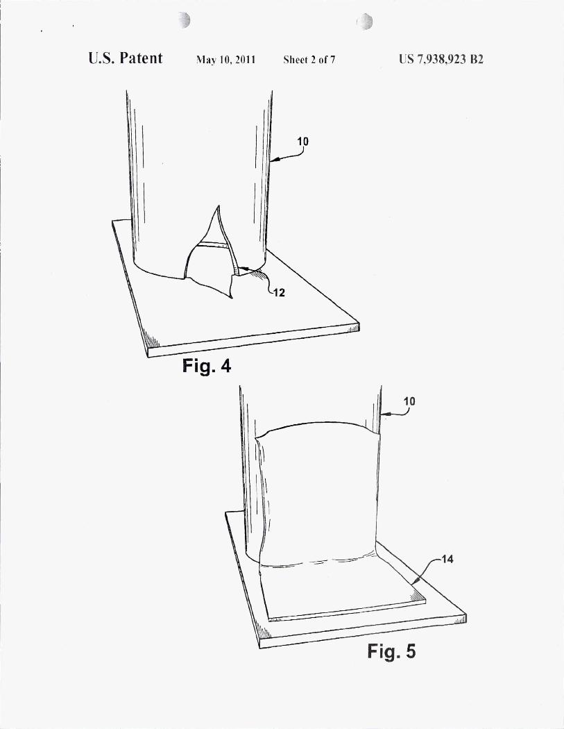
FIG. 4 is ;1 pers pec ti ve view o r a typica l pipe with dlllllage at or near a wall. 110m. or ceili ug:
FIG. 5 is a perspective view of a typical pipe with damage at or ncar a wall. noor. or ceiling rep<lired hy the shape memory polymer composite patch;
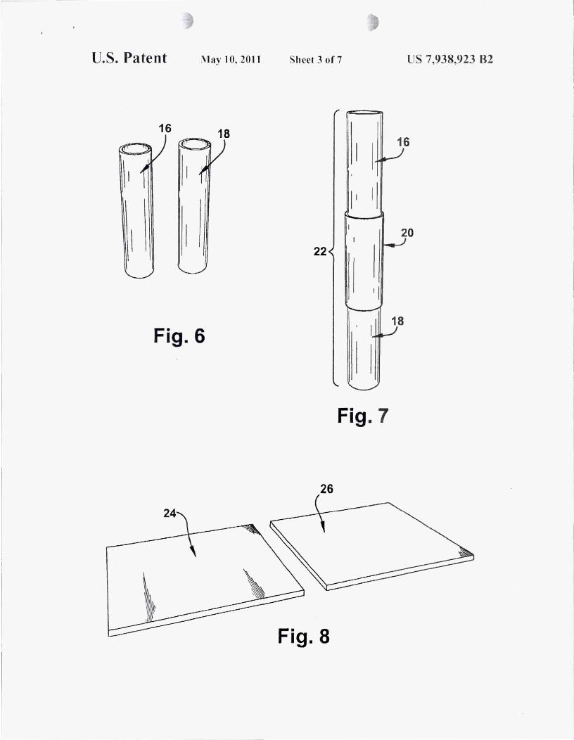
FIG . 6 is a perspective viewoftwll short pieces of pipes thnt ,Ire to be joined toge ther;
FIG. 7 is a pe rspec ti ve v iew o f the single long pipe c rea ted from the two shorter pipes joined by the shape memory polymer composi te patch;
FIG. 8 is a perspective view o rtwo l1at pieces that arc to he jo ined together;
FIG. 9 is a pers pective view ora single pi ece created from the two sma ller pieces jo ined by two sheets of s h,lpe memory pulymer compos ite pa tch;
FIG. lOis a perspective view of a section of a boa t that has a damaged mea:
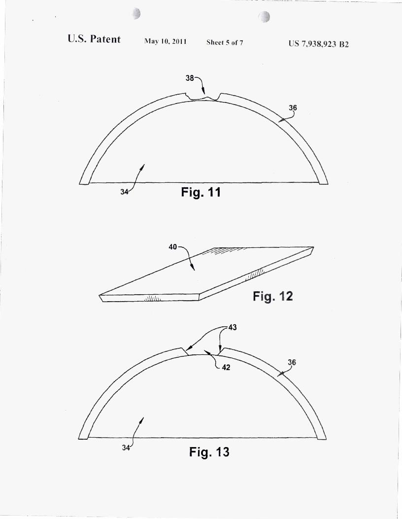
FIG. 11 is a sectional view of the sa me da maged area showing the liberglass coa ting and damaged area;
8 J"l'nc (R5 .2%) in random order to y ield a clear slli ution. Ilenmy I pcrnxide p,lste (.t%) \,hich is 50% benzoyl peroxide. \\;IS then ,Idded tll the resu lting slli utilln (; i11 composition % ,Ire by we ight ). The resu lting sol ution \~as kept wid in a reli'igerator bcl()fe usc. To prepare the shape memory po lyIller res in matrix composi te sheet. a piece oDJ) weavc ca rbon liber is placed on a g.lass sheet. ensuring that there are no s tray libers a nd the carbon liber piece is smooth. Next. po ur some o f the po lymeric react ion mixture onto the cmbon nber. Use a
I {I plastic s411eegee or plastic spreader to spread the resin evenly over the entire suriace or the Inbrie. Thoroughly remove ,Iir bubb les and straighten the tnbric . Place bleeder and breather Illbric on top of the resin son ked cnrbon liber. Then place the en tire system in n high temperature vacuum hag w ith n
1.1 vacuum vnlve stem (IUd apply vncuum thoroughly, ensuring that there are no kaks . C ure the composi te part with the Ilil l Ll~ing cyde: I ) A one-hour linear ramp to 75 ° C in an oven. autoclave. or other rorm of cont rolled heating device : 2) .\ three-hour ho ld at 75" C: ~)A three-hour linearramp to ')00
20 r.; 4) A two-hour linear ramp to I 10° C.; 5)/\. one-hour linear ra mp to 20° C. .\Iter curing, remove from oven il nd allow to cool. Remove vacu um bag. b leeder fabric. breather labric, and glass pintes from composi te.
25 EXAMPLE 2
A polymeric reaction mixture was formulated by mixing
FIG. 12 is a perspective view or tbe shape memory po ly mer 30
composite patch \,ith s lightly angled sides for a better lit of the patch;
vi nylneodeeanoate (10%). divinyl benzene (0.8%). and styrene (SS .2% ) in rnndom order to 10n11 n colo rless solution. Polystyrene granules (30%) were then added to the resulting solut ion. T he resulting mixture was then nllowed to si t at roOI11 temperature with occasional stirring until all the polysty rene granules were disso lved to give a clear. viscous so lution. Benzoy l peroxide (4%) which is 50"10 benzoyl peroxide wns then added to the resulting so lution (a ll composition % are by weight) . TIle resulting polymeric renct ion mixture is
FIG. 13 is a s~'(; t iona l view o r the damaged area a ller the damage area hns been removed nnd n transition nrea from undamaged to damaged area has been created;
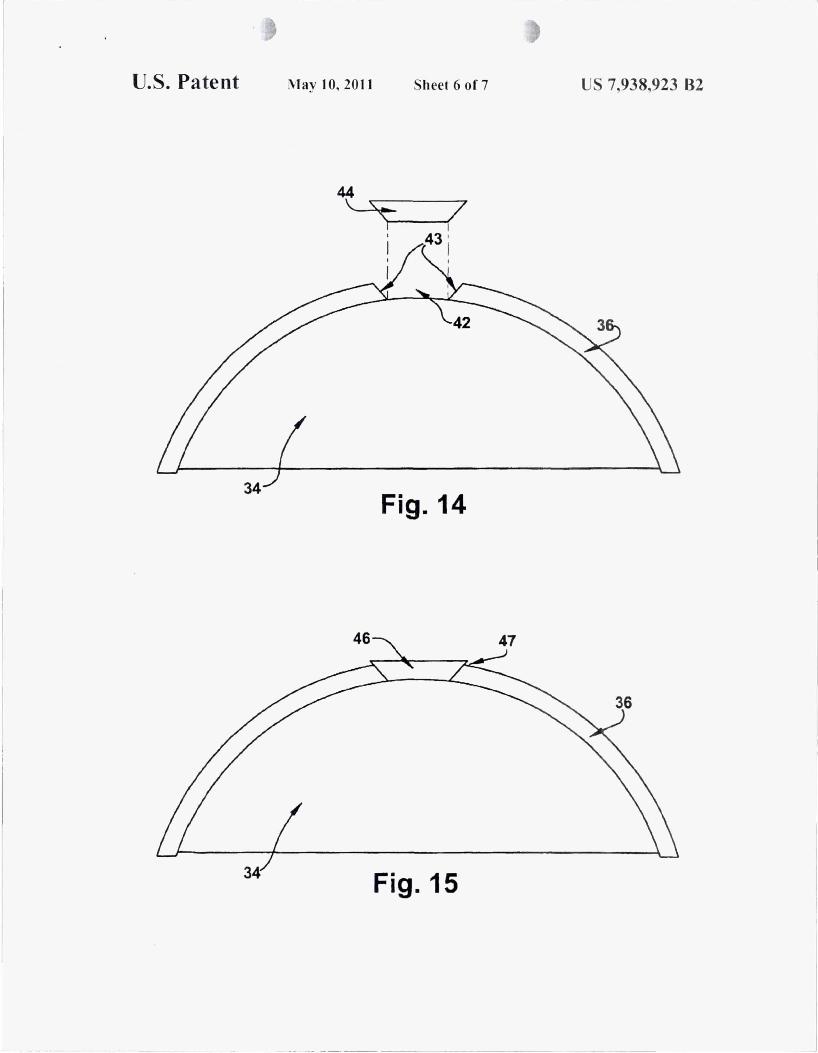
FIG. 14 is a sectional view of the of the damaged area ready )" for repair and the soft composite patch that is ready for molding into the dmnuged area; continually stirred a t or near 25° C, not to exceed 30° C. until
n c lea r so lution is nchieved which can tnke 2 hours or more. 'nle resulting sol utiun is kept cold in a refrigemtor before use . To prepnre the shape melllory polymer resin matrix composite sheet. a piece oDD weave carbon fiber is placed ona glass
FIG. 15 is a sectional view of the o rthe boat hull with the composite pntch essentia lly repairing tbe damaged area w ith some excess patch mnterial extending beyond the origi na l 40
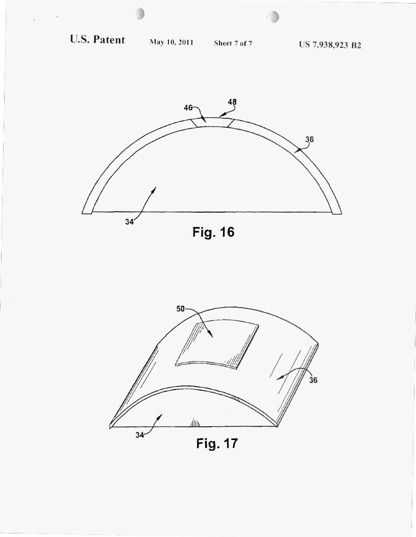
hull; [7 IG. 16 is a sectional view of the machined and sanded
plltch so that the patch and the original hull are flush ; and FIG. 17 is n perspec ti ve view of the hu ll fully repa ired by
the shape memory polymer composite patch.
IJETAILEIJ IJESC RII'T ION OF THE I VENTION
Referring to the drawings in greater detail. the method o f the invention herein is directed 10 labricating and using n composite patch w ith a Sha pe Memory Polymer (SMP ) resin matrix or o ther shape memory mate ri al in the m;]uulacture o f cas tnb le composi te parts .
Exnmples I nnd 2 below describe the exemplary methods n r crea ting pre-form s hape mcmory polymer (S M P) compos
sheet. ensuring that there are no stray fibe rs and the carbon libe r piece is smooth . Next. pour some of the polymeric reaction mixture onto the cnrbon fiber. Use a plastic squeegee
45 or plastic spreadcr to spread the resin evenly over thc entire surlilce of the fabric. TIlOrolighly remove air bubble ' and stmighten the fab ric. Plnce bleeder and breathe r fnbric o n top o r the re in son ked carbo n fi ber. Then place the ent ire system in a high temperature vacuum bag with a vacuum va lve stem
," a nd a pp ly vacuum thoroughly. ensuring that there are no leaks. Cure the composi te part with the /o llowi ng cyc le: l ) A one-hour linear ramp to 75° C. in nn oven. autoclave. or o thcr lo rm o f controlled heating device: 2) A three-ho ur ho ld (I t 75° C: ~ ) A three-hour linear r:Jmp to 90 ° C;.t) A two-hour linear
5' r.llnp to 110° C: S) .\ one hour linear ramp to 20° C .\ner curing, remove Irom oven and <J llow to cool. Remove vnClIum bag. blceder la brie. brent her fab ric. nnd g lass pla tes from composite.
ite pans. In general. the preferred SMP is a sty rene copo lymer based SMP as ui selosed in U.S. Pat. No. 6.759.48 1. however. o ther types o f SM Ps such as cyanate es te r. polyuretha ne. po lyethy lene homopolymer. styrene-butndiene. po ly isoprene, copolymers o f s tearyl acryl<lte and acrylic <lcid or methyl acry late. norbomem: or dimethaneoctnhydron(lp tha- Gil
lene homopolymers or copolymers. malemide and ll ther mtl teria ls ,Irc with in the scope o r the present invcntion.
To achieve llIore than llne fnbric Inyer s imply soak two or more layers of rabrie in the shape memory polYllJer and stack on top uf each o ther. The use o f o ther lilb rics such as carbon Iwnll- libers. spa ndex. cho pped tibe r. r,lIldom liber mat. 1:lbric o r <Iny material. continuo us liber. libe'1?bss. or o ther ty pe or textile lil bric can be uSlxl to replace cilrhon liber in the above 1::<.\ 11 '1 I ~ I
.. \ polymeric re,lction mixtu re was lilfllluiated by mixing vinyl neodecanoate ( 10%). divinyl benzene (0.8%). ,md sty-
() ' ex 'lJl1pks. In EX:lIl1ple ::! it is esscnti :i1 lhat whi le mixing a fter the ~Iddition or bellzy l peroxide tha t the temperature o r the resin be maintni ned below .~OO C ;IS the mixture may become
US 7,938,923 82 9
hnt and exp lmive. Mixing in a co ld w<l ter Dr ice ba th ensu res the temperature \vi ll not exceed .,00 C. It ca n ta ke twn hours or more to fu ll y mix .
:\dd itionally. once cured . the shape memory po lymer composi te C,1I1 be deformed IlX ensy storage. shipping. or illlllledi" tc usc . I f dclllflllcd il,r sturage nr shipp ing. s imply acti vating the shape memory po lYIllt:r rt:s in w ill rt:sto rt: tilt: cnmposi tt: part tn its nriginal. memo ri zt:d shape.
·lllC mt:thod n f repairing a ll typt:s o r components ,lIld the cOlll posi tt: pa tchjn ining sys tem a llutili 7e the sa llle cnlllmon Icanlres. The fo llowing description therelort: rcl ntes to all o f these ICllnlres.
FIG. I shows a typical pipe. 2. with a crack , 4 . FIG . 2 shows
10 a sl'c ti o n o f a bm t hull that hn· sullcred damage. JR. The boat hull is madc n r a liberglass n uter layer. 36. and a lillernr I l)~l\l1 inner layer . .14 . FI(i. II shows a sl'C ti ()na l view o fth c damaged hull . .18. w ith the outer fiberglass layer . .16. damaged fmm a pil'Ce 0 fdebri s . While no da mage is shown to the filler or (i..",m inner layer. 34. if su.:h tlamagc 'HIS prcst:nt . this danwge could be repa ired w ith norma l methods. FIG . 12 s hows a composite pa tch materi :11. 40. made by the process of I:x:\mple I nbove cxcept that liberglass. instead o f ca rbon
III liher. is uscd as the librous Ill a terinl. In order to repnir the damaged area . 38. shown in FIGS. 10 and 11. the dnmaged area mllst be removed. as shown at .. 2 in FIG . 13. and a clean. , mon th tr.lI1sition ;1fI~a is created. shown as 43 . As shown in FIG. 13 the boat hull has been machined to crcnte transi tion a 11nl. essentially square piece 0 ,"shapc memory po lymer resin
composi te. 6 . . \fier activation. the slwpe 11lt: l1lo ry po lYl1ler t5 resin in 6 wi ll become soli and can be ensi ly molded to a va ri ety o f shapes. In the present exa mple. a technicia n. wearing g loves. cnn eas ily mechanically defonll 6 to cover the crnck 4 and fo llow the curvaru re of the pipe 2 as st:en in FIG.
rcgions. "3 . o n " II sides o f the dnmaged area Ii-om undamaged liberg lass composite s trucnlre to the a rea to be repaired, 42 .
Once the sur lace has been prepared for repair lIs ing no rmul methods , the shape memory po lymer composite patch. 40. is activa ted by rni sing its tcmpeml1lre nbove its Tg . A s shown in FIG. 14 the composite patch is then initially deformed. 44, into a shape that will make it easie r to mo ld into the dnmaged
3 where the deformed patch. R. covers the crack ,lIld esst:n- 211
ti a lly replicates the shnpe o f the pipe. ,\ Iler bonding the patch to the pipe with an adhesive the pipe is rcpnin:d nnd cn n continue with no nnal opel1ltions.
-Illis process of patching various holes. cracks. leaks. and o ther damnges is no t limited to simple shapes. FIG. 4 shows 25
n larger ho le, 12. at the joint between a pipe. 10. and the ground, wa ll . o r cei ling. Again, after nc tivmion. the shape memory polymer resin in 6 will beco me so ft and can be eas ily mo lded to cover the hole 12. In the present exnmple, a technician, wearing gloves, can easily mecha nically deform 6 to 311
cover the ho le 12 as seen ill F1G. 5 where the deformed patch,
area. 42, and the trnnsition area. 43 . While the temperature of the composite pa tch is above its Tg • the composi te pa tch is formed and mo lded into the danwged area. 42 . and surrounded by the trnnsit ion area, 43 . so tha t the entire dnma1,led area nnd trnnsition area are essent inlly covered by the patch. As shown in FIG. 15 the now molded composi te patch. 46, has been pl aced so ns to essent ia lly cover the entire damaged area. Add it io nally, the molded patch. because o f its soH and pliable stnte wlli le heated, is able to fi ll in most gaps and crevices and complete ly replicate the entire damaged area and
14, covt!rs no t on ly the hole ill pipe 10, but a lso ensures a good seal between the pipe 10 and the wa ll. ce iling, or floo r. After bonding the pa tch to the pipe and wall, ce iling, o r noor w ith nn adhesive the pipe is repa ired and cnn continue wi th norma l .15
machined transition area . As previously no ted. this process requires no cure time as the compos ite patch is already in an e ssentia lly cured s tate. Once the patch has been mo lded to the desired a rea. simply a llow the patch to cool below its Tg to renlfll the pa tch to a hard, rigid s tate. TIli s process should on ly operations .
Additionally these repa irs can be conducted not only by composi te material but a lso by pure shape memory polymer resins which undergo the same activCltion, defonnatio n, and bonding as seen in the above descrip tion.
Ano ther embod iment o rthe invention is the abi lity to joi n two or more parts together easily in orderto fon11 la rger pnrts . FIC;. 6 shows two short pipes, Iii nnd IH . If it is des ired to create a la rger pipe from these two it nwy be very di Ilicu lt o r time consuming to weld or otherwise joi n these p ipes . Using a composi te patch or patch o l' shape memory material a single pipe cnn easily be nwde out o f 16 and 18 as shown in F1G. 7. After placi ng 16 and 18 end to end in o rder to lim11 a single pipe. the shape memory polymer resin compos ite or pure sha pe mem()ry polymer patch is nctivated and defo rmed around the pipe in o rder to e ffect a j o ining o f the pipes with the deformed patch. 20. After bond ing the pntch to the pipes a ncw long pipe. 22. is crea tcd . This enti re process can be tju ick and reduces the emission a nd usc o f ty pically bo nding o r welding too ls tha t c reate fire and chemica l Iwza rds upo n usc .
This embodiment is not limited to pipes :ll1d can be used to j o in o ther gcometric shapes together. F IG . 8 hows Ila t panels. 24 and 26. that may joined . FIG. 9 shows that w ith the use n ftwo patches. 28 and 30. the t·lat panel s ca n quick ly be jo ined \v ithout defonlJi ng the pa tches or de Il)l111 ing the pands so tha t p:lt ches ca n match the minor changes in the shape o f the bna rds .. \li er bo nding the pa tches to the panels. a ne"" larger p:lI1eL 32. is creat..:d .
. \ nll ther exempkll"y e mbodiment [l rm ides;1 means o f permanen t re[lai r Il)r manul~ctured parts that can s ignil ic:l\1tly reduce the tim e rcq uirl-o fl.x repa ir. Inl ' IG . 10 then.: is shown
wke a few minutes. T he composite patch can be bonded to the o rigina l part
with a variety of systems discllssed be low. Once cooled and 40 bonded to the original part it is possible tha t there wi ll be
some excess materia l tha t wi ll rise above and/or not be flu sh with the o rigina l. undamaged surface. as shown at 47 in FIG . 15. ·111 is excess mate ri a l cnn he removed through sanding or other nwclline processes as shown in FIG. 16 where the fina l
45 s urface. 48 . of the composite pa tch, 46, is llOW tlush with the original parI. FIG . 17 shows a fmal view of the pa tch. 50. use:.-o to full y repair the damaged area . 38. in FIG . 10. "nle composite patch is now flu sh with the surface and may be coated o r pninted as desired. It is to be apprec ia ted tha t these repairs can
,(I be conducted not only by composite materia l but also hy pure shape memory po lymer resins which undergo the same act iva tion, de fo rmation. and bonding as seen in the above dcscriptions. It is al so tu be appreciated that this me thod of perm~lnen t repair can also be used Ill r airplnnl! parts. car parts.
" ;1I1d :lIly o the r manufactured part that can he repaired usi ng composile materia l.
In order to bond the compos ite pa tch to a variety of syste ms. the adhesive must be chosen very care fully. There a re a varie ty o I'commercially-availnb le mJhesive sys tems for use in
611 bUild ing shape memory polymer composite pa tches to dinert:nt substl1ltes. T he w ide range o I' adhcsives w ill a id in devel opi ng d iflcrent p,He h "ys tems lilr di l1i.:rent appli ca tio ns . Some ;Id hesiws ;Ire :t":fOspace compatibk \v hile o ther.; C,\I1
un ly be u"cd fl1f g.round ap pl icil t ill ns o r muss pruduct.-u it":l11s. fl.' Cry(J g~llic co l11[l:lt ib le ad hes ives a re ;lisa ava ilable rLl r use in
repairing. cryog.enic pipes and tanh. T hese adhesives can be d ivided in tu t\\O categories: thertlwlly cured acl hesives :lnd
US 7,938,923 B2
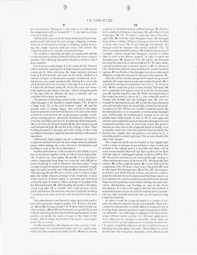
1 1 prl's,; urc sensi tive adhesives. rhe thlTnwlly cured adhesives <: hllsen can be cured ;It or ;Ibove till! tr;lIIsition telllper;lturc o f the sh;lpe memory po lymer com posite ;IS preSSllre <lnd heat ~Ire applied to t.;ure the ;Idhes ive. ;lIld the patch is so n ~ lIld
e:asi ly Ilmlled arllund the area tn be patched. The pressure , ensitive ;Idhes ives arc eITc(.:t ivl! for 4uick repa irs in se;J\ ing spaces that t.;ontain diflcrentl!llVironments such ;IS the inside:
12 The Ill ll ll\~ing ;Ire l'xamplcs of the process nf bonding
shapc memory polymcr composites to subs tr:ttcs according to :tli aspL'Cts nf the invention:
l iX.\ MPI F 1
In order to bond a shape mcmo ry polymer composite patch n f pressure vessl!is ;lIld gas o r liqu id condui ts. Thcse adhesives allnw for a 4uick "baml:Jge-type" approach un ti l ~ I more permanent solution t.;ould he adl il!vcd. The fll ll nwi ng adhe- III sives cou ld be uscd for various applications. but is not intended to limit adhesives w ithin the scope of the present invention to only those listed below:
to liberg lass. the ;1 rea around the dalllagL'<.l portion of a part or thearea ncar the port inn of the part to hejoinL'<.l to «nother. thl:! applit.;;lble area is scu lr sanded and so lvl:! nt wiped tu ensure a cle:Ul. smooth bonding surface .. \dditionally. scuff sand and solvent wipe the s ide of the patch to be bonded to the substmte. Using 1M's <)48S PC High-Perfornwnce .\dhesive Tr..lIls le r Tapc, appl y the tape to thc patch manua lly leaving Thernwlly Cured Adhesives
LORD Corporation Products 310.VB Epoxy Adhesivc 7S42:\/I :, Uretha ne Adhesive
3M Products Scotch-WeldAf' 563 K f'il m .\ dhesive Scotch-Weld AF 163-2 f'i lm Adhesive Scotch-Weld EC 3333 B/ A 2-Part Paste Adhesive Scotch- Weld EC 3448 Paste Adhesive ( I-Part )
Loetite Products Hysol,g) EA \1309.3 NA Epoxy Paste .\dhesive Hyso l'B> 61S I-Iyso l'\!l U-OSFL Hyso l'ID EA 9361 Epoxy Pas te. dhesive Hyso l'l\) EA 9628 Epoxy Fi lm :\ dhesive I Iyso llw EA 96l)5 Epoxy Film Adhesive Hyso l@ EA 9696 Epoxy Film Adhesive
Pressure Sensitive 3M Products
9244 Stmctural Bonding Tape 468 MPR Structllfa l Bonding Tape 9485 PC High-Perfonmlllce Adhesive Transfer Tape
Rudnick Converting, Inc. Pmducts P02~Multi-purpose Double-Coated Splic ing &
Mounting 11 98- UHA Adhesive Tr..llls1i:! r PSG-Multi -purpose Double-Coated C loth Tape
The thermally cured adhesives can be applied by: I ) forming the shape memory poly mer composite pa tch around the area to he honded (without adhesive): 2) ;lpplying adhesive to the patch; and then 3) bo nding the preformed patch to the damaged arca through themw l cu re . This approach is the easil:!s t and cli:!anest method ror using paste-typl:! adhl:!sives. This method may be enhanced by using vacuum pressure during thennal cure and choosing a n adhesive that has a cure temperature nbove the transi tion temperanlre of the shape memory po lyme r com pos ite used lor the pat ch. This would ;tl low for a more intimate intcrface berween the patch and the substra te during cure. This helps promote distri buted load transfer thruugh the adhesive.
t5 the backing on the udhl.!sive. Using the patch from Example I hea t the patch above its transition temperatllre in ;U1 oven which is a t or near 90° C. Remov~ the patdv'adhesive ii-olll till:! oven, peel away the adhesive backing and lann patch to fiberg lass sur l ~ce manually or with assistance of a vacuum
"" p;]d or bagging.
EXAMPLE 4
In o rder to bond a shape memory po lymer composite patch 25 to sta inless steel the area arowld the damaged portion ofa part
o r the area near the portion of the part to be joined to another is scuff sanded and solvent wiped to ensure a clean. smooth bond ing suriace. Additionally scuffsand and solvent wipe the side of the pillch to be bonded to the substrate to ensure 11
30 smooth bonding surface . Apply a thin, even layer of Loctite HYSOL UOS-FL paste adhesive to repa ir area on stainless steel. Using the pa tch frum Example I hl:!at thl:! patch abovl:! its transirion temperature. Fom) patch to repair surface manually or with a heating blanket using vacuum pressure. Cure adhe-
35 s ive according to manufacnlrers recommenda tions using temperature controller cOllnected to the heat ing hlankct or other method. Remove vacuum blanket a l1er cure.
The bonding of the hape memory polymer composite patch can be dunl:! to v"riuus uthl:!r substrates, ml:!tal cans, car
40 fende rs, other composite parts, using the method of Ex run pie 3 above. The methuds described above are usefi.11 and one method shou ld be chosen over the other method depending on the appli cation. '1l1ermally cu red adhesives shou ld genera lly be used lor higher strength app licat ions where time-to-repair
45 is less critica l sllch as airplane parts. load-bearing stmctural parts, and o tlll:!r parts wi til high strength or other lllt:Chanjcal properties as described in Example 4 above. Pressure sensitive adhesives should generally be used ror lower st rength applications where time-to-repair is more critical or the cost
'" o r st rength is no t as important such as leaki ng pipes o r sim pl e cosmt!tic repairs .. \ lier bonding with the correc t adhesive and composi te pa tch. the repaired part may be used nonnally.lll is includes liowing liquids or ga ses through pipes at norma l
Pressure adhe ives are applied to the shape ml.!mory polymer cllmposile patch manually wi lh the backing p!lper len 5:\
intact. When repa ir is des ired. I ) the patch/adhesive combination is hented ;IixlVe the trans ition tcmperatllre of the co mposite patch, 2) the backing paper is removed and 3) the p«tch
oper..lting tem pera tures alld pressures. Bec,llIse o f the propel1ies in.herent in shape memory po ly-
mers, composites utili zing shape memory pn lymer as the resinillatrix can be temporari ly so ftened. reshaped, and mpidly ha rdened in rea l-time to function in a v:lriety of stmcnlral configu ratio ns. They can be fabricated with nearly any ty pc of is fomled nwnua lly or with assistance and adhered simulta
neously to the substr..,te. TillS lIlt:thod of;,dhesive app lication prior to usc enables very laS l repair sccnarios. :\dditiona lly
6" 1: lbric. and creative reinforcements can result in dranwtic shape clmnges in functional stmctures and they are mHchin"hie. lo r light or eiL'C tCllmagnet ic r;ldiati on :lctivated sh:'pe memory
pll lynwr t.;ompn: ite:s. the patch ~Idhe:s i ve cllmbination is ac tiva ted by ;Ipplica ti ll ll llf sa id cJL'Ctronwgnetic radiation. the: p;lIch is IlJrllled m:lllually or wit h o thl:!r mechanical ;Is sista nce o~ to tht: subs trate ,lIId deactivated \~ith electromagnet ic r:td in-tion.
Thcreill re . it <.:: In readily he seen that the pre:sent invl!n tion pro ' ides a quick dnd easy way to uti lI/.e <.:om posi te and , hape mcmory polymer t<:dlllo log)' to create a patch tha t has the tlexibi li ry of dUel tapt! \~i th thl:! perlomwnce o f compos ites ;llId simib r metal subs tant.;es.

r-
US 7,938,923 82 13 14
It is tiJen:ll)re .lpparenttiJ.lt nne exemplary cmbmlil11cnt nf thc invcn tion provides a methou Illr rep:liring I llanlll~tctured
parts nf the typc having a damagl.'tl a re<l tlterl.\l!". . \ re p'lir ma terial is prelilrJlleu int n a desired sha pe. Thc repni r material m<ly cn lllprise, for cxamp le, a slwpc memnry pnlymer. Thc shape 111eI11(1), pnlymer is activ'ltcd so th<ltthc prclormeu rcrair malcrial b,,'Comcs so li. a nd it is thcn dclllnlled inlo n sh'lpe ad'lptcd Il1r the rcpa ir functi on. The shape I11CmLlry r n lymcr is Ihen deact ivated whi le maintaining the po lym<.!f in its dcfnrmcd state. Thercafter, the delo rmed ~hape memory pn lymer is bondcdtll the d:l1lwged aren of the llWllUf(lctured
pnrt.
.\n llther as pect \)r the invention compri ses joining a plur:lli ty or parts tngether via lise ni'l lll' sha pe memory materia ls. I le re. the parts arc juxtaposed so that a t least one joi nt or joinder mea is Illrll1l.'d. A prelormc-d s hap~ memory mater ia l
, 'suc h as a shnpe memory pnlymer is provided ilnd ac tivilted. '!lle shape memory materi al is thell applied to the joint or jni ndcr mea .1I1d defi.mnccl into a desired shape. '111e shape 'mcmory ma terial is deactivated w hile maintnining it in it s dcfnnned shape. The dcl(lrml.'Cl shape is then bondc-d to the
\II jnint a rea tn ellL'Ct joinder nf Ihe parts togcther. . \ltho llgh tlli s invention has been described wi th respect to
certain preli.:rred embodiments, il will be appreciated that a w ide variety ofe4ui v,lients may be substituted fur those speci lic c lements shown and described herein, a ll w ithout depart -'111e rep<l ir material m<ly comprise a cllmpusi tc material
rOrnH:.'Cl from nt least llnc layer of nbrous material in cO lJlbi nation with a shape me1110ry polymer. In one form, the fibro us materia l may be embedded w ithin the sha pe memory po lymcr or. the fibrou s material cnn be impregnated with the shape
15 ing Irom the spirit and scope of the invent ion as defined in the appended clai ms.
memory po lymer. The nbrous material lJlay be chosen Irom carbon nuno fi- 21.1
ners, carbon fiber, spandex , chopped fiber. random fiber ma t, la bric or any ma teria l, con tinuous liber, fiberglnss , or o ther ty pes of textile fibers, yam s, and la brics. For example, the fib rous material may be present ill the Illflu of a f'lat wuven article , a two -d imens iona l weave, or a three-d imensional 25
weave. . !lIe shape memory polymer may be selectedlrom a host o f
pll lymer types inc luding styrene, cyanate esters. ma leamide po lymers. epoxy po lymers , or vinyl es ter po lymers. In some cases, the shape memo ry po lymer will be a thermoset res in. 30
Wha t is c laimed is: I . A method lo r repa iring ma nuf..1cturcd parts hav ing a
damaged arca comprising: a . prdo nning a repnir materi .d into a desired shape, said
repair material comprising a shape memory polymer; b. aClivating sa id shape memory po lymer such that sa id
prefonned repair material becomes soft : c . defomling said pre\ormed ma terial into a shape adaptcd
for sa id repairing, wherein sa id defomling is achieved hy mechanica l means;
d . deactivating sa id shape memory polymer whi le mainta ining sa id repair materia l in it s detomled state ; and
e . bonding said defonned repair mnterial to sa id d,U11 aged area of saidmanufacnlfed part. The repair material may include a thermal enefb'Y genera
ti un means embedded therein . Such thennal energy gener.Jtionmeans muy comprise, for example, thermally conduct ive fibers or e lectrica l conductors .
In another excmplary embodiment o f the invention, activation of the shape memory polymcr is achieved hy heating the polymer above its transit ion temperature. The heating may, for example, be e ffected by inductive hea ting, ho t air, o r
2. The melhod o r claim 1 wherein said repair malerial comprises a composite material formed from at least one layer o f fi brous material ill combination with aid shape
35 memory polymer.
by heat !<Imps . Adui tiona lly. when the repa ir ma teri al comprises a thermal energy generation means embedded therein, 40
it may be act ivated by applying electrical current to the thermal energy genemtion mea ns.
3 . 111e method of claim 2 wherein said fibrous materia l is embedded in sa id shape memory polymer.
4 . 'TIle method of claim 2 wherein aid tibrous materia l is impregna ted wi th sa id shape memory polymer.
S. TIle method of clnim 2 wherein said fibrous materia l is carbon nano-fibers , ca rbon fiber, spandex, chopped fiber, random fibe r mat, fabric orallY ma teria l, continuous fibe r, fiberg lass , or other type of tex tile fabric.
6. The method of claim 2 where in sa id fi brous materin l is in In yet another exemplary embodiment of the invention,
activat io n o rthe shape memory po lymer may be achi eved by application of electromagnetic rad imion such as in the foml o f visible ligh t or ultraviolet lig.hl.
45 the fo rm o f a lia t weave, two dimensiona l weavc, or three
TIle deformation step may be achievt.'Cl via mechanica l menns suc h as by pres ing in a press mo ld or by cxtnlding the ma teri al through a ro lling uie mold.
In one exemplary embodiment orthe invention, the shape 511
memory po lymer is deac ti vall.'Cl by rt.'Cl ucing the temperature thereo f to below its activation temperature. This can bc accomplished whi le the po lymer is being press mo lded so thelt uu ring the press molding, the polymer is maintainl'd at a temperature below it s activation temperat!lre. Furt her, the " deactiva ti on o f the shape memory po lymer may be achieved by ap pl ica tion or ekctromagnetic radiation such as vis ible light or ultravi olet light thereto.
dimensiunal weave pattern. 7. The method of cla im 1 wherein said shape memory
polymer is sdected from the group cons isting of a sty rene shape memory po lymer, cyanate ester shape memory po lymer, ma lenmide sha pe memory polymer, epoxy shape memory polymer, or v inyl e ster shape memory polymer.
8 . Thc mcthod of claim 1 wherc in sa id shnpc memory polymer resin is a thermoset r"sin.
9 . The method of claim 1 wherein ~a i d repnir materia l compriscs an l:mbeddcdthenllal energy gcneration mea ns .
10. The method of c laim 9 wherein said embedded thermal energy generation means comprises the mlally conductive libers.
-!lIe manufacnlred part may be co mpoSl.'Cl o f any ma teria L such as meta l, woou, plas tic. glass. or in itself Illay be a com posi te part or simi lar materia l. Tlle bnnding step in accordance wi th the invention may be ach ieved via n host o f co n-
II . The method of claim 9 whercin sa id therma l energy 611 g~nerat io n means comprises anl:lcc trical conductor.
\ entional Illeans ~uch , IS via thermally ClIrc'd :Idhcs ivcs or press llre sensitive "dhcsives .
In :Ilklitinn In :,ha pe memory p\l IYlllers. ll thl'r sha pe memo ry materi.lI s slll;h as shape memory alloys may be menti\l ncd as being e IlL'l:ti ve.
12. The me thud o f claim I wherein said activation o r said sh;lpe memory polymer is by heati ng sa id shape memory r l1lymcr above its tra nsit ion tel11per~l lllre .
IJ . Tht.! ml:thod o f claim 12 wherein s,lid heating is by 0 ' illd uc t i~e lwat ing, hot air \l r hy heat lamps.
14. The methud o f clai m 9 wherein sa id repai r materia l comprises :111 e mbt.'dued thernwl energy genel<ltion mC<l1lS
US 7,938,923 B2 15
~ lI1d said hea t ing is by ,Ippl ying eiL'ctrira l c urrcnt to s~l i d
elllh\.'t!tkd thermal energy genera tio n mea ns. 15. The Illdhod orclailll I "herein said ~ 1l:ti v' lti o n u r said
shape lllenHlIY polyml.!r is ac hil.!vcd hy ,lpplic,ltion o f l.! kctrn
magl1l!tic radi 'ltion . 16 . T hl.! ml.!thod or c la im IS where s'li d dectronwgnl.!t ic
mdiat ion is visible light or ulimvio let light. 17. The method lIf c laim I v"herl.!in s,lid deformi ng by
mechanical means is accom plished in a press Illo ld . III 18. The method o r cl 'lim 1 where in dcrorming is accom
plished by drawing.materialt luo llgh a m lli ng die mo ld . 19 . 'nlC method of c la im I wl1t!rein said deactivation orsaid
shapc memury polY1l1cr is achiewd by rcducing the:: le::mpe::r.lture of sa id shape mcmory po lymer below its ac ti vation tem- t5 pera tu re .
16 <:mbcddcd therl.!in and ,a id heating is achieved by appl ying elect rical current to sa id embedded Ihen11a l energy gencr;lti Ull l11l"lns.
35 . The method " I' c la im 24 whcrein sa id ac ti va tion 01' said shape memory polymcr is al.!hievL't! by applica tilln o f clcctmnwgnl.! ti c rad iation .
.16 . T he method o r c laim 35 where sn id e lectromagnetic r' ldia tion is visible light or ultravio let light.
37 . '[he mdhud o l' c la im 24 whcrein sa id defo rming is accompl ished in a press mo ld.
38 . The mcthod of claim 24 whert:in defo rm ing is nccumplished by drawing material thmugh a ro lling die mold.
39. T he mdhud ufclaim 25 whe::rein said deactiva tion o f sa id shape mcmory polymer is achieved by reducing the temperature of sa id shape memory pulymer tu below its activation tempernture .
40 . TIle method of claim 25 wherein said denctivation of 20 . The n1l!thod of c la im 1 wherein said deac tivation 0 f said
shape memory polymer is achieved by appl icat ion of e lectromagne::t ic radiatiun.
21. The method of c la im 19 wherein sa id nid elec tromagnetic rad iatiun is visible light ur ultraviu le t light.
, <l id s hape memury pulymer is achieved by applicat iun of
20 dectronwgnetic radiation.
22 . The method of cbim I where in sa id nwnul'actmed part is composed of metal. wood, plas ti c , g lass. o r is another composite pan o r o ther similar mll te::ri a l.
23. The method of claim I wherein sa id bonding is 25
achieved by a thenlla lly cured adhesive o r a pressure sensi tive adhesive.
24 . 1\ process for repairing nwnufactured pan s having a damaged area comprising:
a. preforming a shape memory mater ia l into a desired )(1
geometric shape; b. activat ing sa id shape memory material such tha t sa id
sha pe ml.!mory material becomes su ft; c . Jefofllling sa id shap e memory materia l into a shape )s
adaptcd for sa id repairing, wherein said deforming is accompli shed by mech'Uliea l mea ns;
d . deactiva ting said shape memory malerinl while mainWining it in it s defo rmed sta te; and
e. bonding said ddo rmed shape memory materia l to sa id 40
damaged arca of said manufacturcd pan . 25 . The method o rcla im 24 \~ he rei n sa id shape memo ry
materia l is a shape memory polymer. 26. TIle method o f c laim 25 wherein sa id shape memory
polymcr is selected from tbc g roup consis ting of a s tyrcne 45
shape memury pulymer, a cyana te ester shape mt!mury puly mer, a maleal1lide shape me::lI1o ry po lymer. o r ,Ul epoxy shape ml.!II1Ory po lymcr.
27 . The method of c lai m 26 where in said shape memo ry po lymer resin is a thermoset resin .
28 . The method of cla im 24 whert!in sa id shape memory ma terial is shape mcmory a lloy.
41. The method o f cla im .to wherein sa id a id elec tromagnetic rad iation is visible light or ultravio le t light.
42 . T he method of claim 24 wherein sa id ma nufactured part is composed of meta l, wood, plastic , g lass, o r is ano ther composite pru1 or o ther simi lar materia l.
43 . T he method of c laim 24 w herein sa id bonding is nchieved by a thenlla lly cured adhesive or pressure sens itive adhesive.
44 . A method of j o ining a p lu ra lity of mallllfacnired parts together comprising:
a. juxtaposing said pans so tha t at least one jo int area is I0 n11ed;
b. prov iding a prefornled shape memory material; c . ac tivating sa id preformed shape memory materia l and
applying it to sa id j oint nrca; d. de forming 'nid prefonning shape memory material into
a desired shape. wherein sa id delornling is accompi ished by mechanical means;
e. deac ti va ting said shape memory material while maintaining it in sa id defomled shape; and
f. bonding. sa id defonlled shape memory materia l to sa id jo int a rea.
45. A method as recited in claim 44 wherein said shape memory ma tcrial comprisL'S a shape meluQry polymer.
46. A methud as recited in claim 45 wherein sa id shape memory materi al comprises a composi te formed from at leas t llne layer o f fibrous materi al in co mbination with a id shape memory polymer.
47 . A method as recited in claim 46 w herein sa id fibro lls materia l is embedded in sa id shape memory po lymer.
48. A me thud as recited ill claim 46 wlwrein said fibrous lIlateria l is impregnated with said shape memory po lymer.
49 . The method o f cla im .t6 wherein said tibrous materia l is 29. The method uf c la im 24 whe re in said shape memory
polymer comprises an embedded the n11al energy generation me:1 ns.
30 . The me thod o f cla im 29 where in said cm beddcd thermal energy gencration means compri ses thermally conducti ve tibers.
' ) chosen Irom ca rbon nanu-fibers, c:trbon tiber, spand ex , c hopp<:!d liber, random fiber mat, f[lbric of any matcriaL continuo lls Iiber. tiberg lass, or o ther ty pe of tex tile fabric .
31. The me tlhld o f cla im 29 wherei n sa id then11al enl.!rgy gener;ltion me::ans comprises an e k'Ctrical condul.!tu r.
32 . The method o f clai m 25 v" here in sa id activa tio n o l' sa id , Iwpe mcm()(y po lymer is ach ieved hy he;lting s;lid s l1:1 pe memory pll ly mer abll\'e its li~ 1I1 s i t io n lempl' ranlre.
3.1 . The ml.!thllu or cla im :12 \~hert:i n said hea ting is by in luctive heating. ho t a ir. or heat lamps .
.14. Thc method o rcla im 32 "herci n s<li d shape mcmory pulymer compri ses a thermal energy g<:ner<l ti on mea ns
SO. The method o f claim 46 whercin said libroll s materia l is in the fo n11 o f a lla t weave, two dimensional weave, o r three
611 dimensio nal weave pattern. 51. T he method o f claim 45 wherein said sha pe memory
polY1l1<.! r is se lected from the group cons is ting o f a ' ty rc ne , hape nH.!mol)' pUly mer, cyanate ester : hape IIlCmllry po lymer. /J1,t1 c<Jm ide sfwpe memory polymer. epoxy shupe
r, 5 111l.!11l0 ry pnlymcr. ll r viny l csler shape memory polymer. 52 . T he method o f claim 5 I v"hcre in sa id shape 1l1ClllOry
polymer resin is a thermoset res in.
l

l_
US 7,938,923 B2 17
SJ . The method of ci;lim .t4 where'i n sa id pre'fonned sklpe memory nwterial (:omprises ;111 embedded thennal energ.y g.eneration nll:i.lllS.
54 . rhe method u f cbim53 wherein sa id cmbedded therma l cnergy generatio n me""IS comprises thermally cl1nduclivc Iibers.
55 . The method o f claim 5] ", herein sa id thermal energy gcneration means comprises an e1ectrieal conductor.
56 . The Illdhod o f"cbi lll 45 ,,, herei n sa id acti v;l tio n oCsaid slwpe memory polymer is [Iehieved by healing said shape III memory polymer to above its trnns iliontemperature.
57 . The method nf c lai m 56 wherei n sa id heat ing is achieved by indlH; ti ve heating, hot [Iir. <l r heat ""lIpS.
58 . The method o f cla im 45 wherein sa id shape memo ry po lymer inc ludes tht!rI1w l energy generation means embeddt;.xI therein a nd sai d heating is ac hi eved by ap plyi ng ekctrical t, c urrent to sa id embedded thermal t:1\I:rgy genera liun mcans.
59 . The method o f cbim45 wherein sa id acti va tio n o f said shape memory pulymer is achieved by application of e1ectromagne tic ratlia tion.
60 . The mt:thod o r c la im 59 where s[lid electromagnetic ell rad iation is visible light or 1Iitraviokt lilYlt .
18 6 1. The method o f claim .t4 ,,,herein said dcJllrlning is
accomplished in .1 prcss mo ld . 62 . The method o r clnim 44 \I,herein deillfilling is m;com
plished by draw ing mater ia ltllmllgh a ro lling die nltlld. 6] . The method o f claim 45 wherein said deactivation or
,aid ,h;lpe memory polymer resin is achiev<.x! by retlucing the temper[lI ure o f sa id shape memory po lymer below its [Ic tivation tempcrature.
64 . The method or claim 45 w hcrein said dcactivation of said sl];lpe mel110ry po lymcr is ac hieved by <Jpplication of electrl1nwgne ti c rndiation.
65 . ·Ille method o f c laim 64 \vhcrein sa id e!t:ctromugnetic radi<ltion is visible lilYlt or ultravio let light.
66 . T he method o f claim 44 \" herein said mallui:lcturcd p;]rt is composed of metal, wood. plastic . glass. or is ano ther composite part or o ther s imilar material.
67. The method of claim 44 wherein sa id bonding is by thcnnally cured adhes ive or pressure sens itive adhesive.
* * * * *