iii - core.ac.uk · I would like to thank to Mr Supa’at Zakaria and Mr ... Kawalan pelepasan...
51
Transcript of iii - core.ac.uk · I would like to thank to Mr Supa’at Zakaria and Mr ... Kawalan pelepasan...


iii
For my beloved mother and father
For my beloved husband

iv
ACKNOWLEDGEMENT
Alhamdulillah, I am so grateful to Allah S.W.T for giving me strength and guidance
throughout my studies and to complete this thesis. First of all, I would like to express
my gratitude to my supervisor, Assoc. Prof. Dr. Engr. Abdul Mutalib bin Leman for
becoming my motivator, inspirer through all the stages during my Master journey.
Without his supervision and invaluable time spent with me, this thesis would not been
completed successfully.
I would like to thank to Mr Supa’at Zakaria and Mr Dafit Feriyanto for their ideas and
assistance throughout this thesis.
I would like to extend my gratitude to my beloved parents and my husband who always
provided me a moral support and guidance in the completion of this thesis. I am so
grateful for the love, support and educational opportunities that they have provided for
me throughout the years.

v
ABSTRACT
Automobile exhaust emission control is one of trending issues in automotive research
field. Ceramic and metallic catalytic converters are the most common types of catalytic
converters. Most current researches focus on the modeling and characterization of
catalytic converter and there is a lack of exhaust gas conversion data of different catalyst
types that correspond to real engine operating condition. This project focuses on
comparing and analyzing the performance of ceramic and metallic catalytic converter on
its conversion efficiency. Mitsubishi 4G93 1800cc gasoline engine was attached with a
dynamometer and Kane Auto 5-1 series exhaust gas analyzer were used for emission
measurements of carbon monoxide (CO), hydrocarbon (HC) and nitrogen oxide (NOx) in
different speed and constant load. The experimental results of the engine performance
and exhaust emission were used to compare the performance of ceramic and metallic
catalytic converters in reducing the concentration of the exhaust emission without
affecting the engine performance. Based on the result, metallic catalytic converter
showed a higher 97.9% reduction of CO concentration reduction emission as compared
to the ceramic catalytic converter. The ceramic catalytic converters on the other hands
showed better reduction of NOx and HC concentration of 87.2% and 85.4% percentage
of reduction. It can be concluded that metallic catalytic converters performs a better
exhaust gas conversion on high temperature condition at reducing CO emission while
ceramic catalytic converters reduced HC and NOx emission more effectively due to its
lower thermal conductivity.

vi
ABSTRAK
Kawalan pelepasan ekzos automobil adalah salah satu daripada isu yang mendapat
perhatian dalam bidang penyelidikan automotif. Penukar pemangkin seramik dan logam
adalah jenis penukar pemangkin yang biasa digunakan. Kebanyakan kajian semasa
memberi tumpuan kepada model dan pencirian penukar pemangkin, di mana terdapat
kekurangan data berkaitan penukaran gas ekzos bagi mengkaji prestasi pemangkin yang
berbeza dan sepadan dengan keadaan operasi enjin sebenar. Projek ini memberi tumpuan
kepada perbandingan dan menganalisis prestasi penukar pemangkin seramik dan logam
dalam kecekapan penukaran. Enjin petrol jenis Mitsubishi 4G93 1800 cc yang
disambungkan dengan dinamometer dan penganalisis gas jenis Kane Auto 5-1
digunakan untuk pengukuran pelepasan gas karbon monoksida (CO), hidrokarbon (HC)
dan nitrogen oksida (NOx) dengan perubahan kelajuan dan beban yang tetap. Keputusan
eksperimen prestasi enjin dan pelepasan ekzos penukar pemangkin seramik telah
dibandingkan dengan penukar pemangkin logam dari segi kecekapan mengurangkan
pelepasan ekzos tanpa menjejaskan prestasi enjin. Berdasarkan keputusan yang
diperolehi, penukar pemangkin logam menunjukkan pengurangan CO yang lebih tinggi
iaitu sebanyak 97.9% berbanding penukar pemangkin seramik. Penukar pemangkin
seramik pula menunjukkan pengurangan yang ketara bagi kandungan NOx dan HC iaitu
87.2% dan 85.4% kecekapan penukaran. Analisis kedua-dua penukar pemangkin
seramik dan logam menunjukkan prestasi yang berbeza dalam mengurangkan pelepasan
ekzos. Kesimpulannya, penukar pemangkin menunjukkan penukaran gas ekzos yang
lebih baik pada keadaan suhu yang tinggi untuk mengurangkan pelepasan CO manakala
penukar pemangkin seramik mengurangkan pelepasan HC dan NOx yang lebih berkesan
akibat kekonduksian terma yang lebih rendah.
vii
TABLE OF CONTENTS
TITLE i
DECLARATION ii
DEDICATION iii
ACKNOWLEDGEMENT iv
ABSTRACT v
ABSTRAK vi
TABLE OF CONTENTS vii
LIST OF TABLES x
LIST OF FIGURES xii
LIST OF SYMBOLS AND ABBREVIATION xvi
LIST OF APPENDICES xviii
CHAPTER 1 INTRODUCTION 1
1. 1 Background of Study 1
1.2 Problem Statement 4
1.3 Objectives of Study 5
1.4 Scopes of Study 5
1.5 Significant of Study 6
1.6 Thesis Organization 6
CHAPTER 2 LITERATURE REVIEW 7
2.1 Introduction 7
2.2 Regulation of Vehicles Emission 7
2.3 Performance and Emission of RON 95 and RON 97
Gasoline
9
2.4 Emission of Gasoline Engine 11

viii
2.4.1 Emission of Nitrogen Oxides (NOx) 11
2.4.2 Emission of Carbon Monoxide (CO) 12
2.4.3 Emission of Hydrocarbon (HC) 12
2.5 Emission Standard of Gasoline Engine 13
2.6 Factors Affecting Exhaust Emission 14
2.6.1 Air-to-Fuel Ratio 15
2.6.2 Cold-Start Condition 17
2.6.3 Exhaust Temperature 19
2.7 Catalytic Converter 19
2.7.1 Substrate 21
2.7.2 Washcoat 22
2.7.3 Catalyst 23
2.8 Ceramic Catalytic Converter 23
2.9 Metallic Catalytic Converter 26
2.10 Advanced Material Development 28
2.11 Experimental Analysis of Exhaust Emission
Testing
29
2.12 Research Gap 35
CHAPTER 3 METHODOLOGY 37
3.1 Introduction 37
3.2 Research Flowchart 37
3.3 Catalytic Converter Selection 39
3.4 Experimental Facilities and Equipment 40
3.4.1 Exhaust system Modification 40
3.4.2 Engine Test Bench 41
3.4.3 Eddy Current Dynamometer 43
3.4.4 Fuel Measurement 46
3.4.5 Temperature Measurement 47
3.4.6 Exhaust Gas Analyzer 48
3.5 Operating Conditions and Testing Sequence 50
3.6 Analysis of Engine Performance 52

ix
3.6.1 Brake Power Calculation 52
3.6.2 Brake Mean Effective Pressure 52
3.6.3 Brake Specific Fuel Consumption 52
CHAPTER 4 RESULTS AND DISCUSSION 54
4.1 Introduction 54
4.2 Engine Performance Analysis 54
4.2.1 Effect of Brake Power On Engine
Performance
55
4.2.2 Effect of Brake Mean Effective Pressure on
Engine Performance
57
4.2.3 Effect of Brake Specific Fuel Consumption
on Engine Performance
59
4.2.4 Effect of inlet and outlet temperature on
Engine performance
61
4.3 Analysis of Engine Emission 63
4.3.1 Effect of Engine Speed on Engine Out
Emission
63
4.3.1.1 CO Emission 64
4.3.1.2 NOx Emission 67
4.3.1.3 HC Emission 69
CHAPTER 5 CONCLUSIONS AND RECOMMENDATIONS 72
5.1 Conclusions 72
5.2 Recommendations for Future Works 73
REFERENCES 75
APPENDICES 85
x
LIST OF TABLES
1.1 Estimated average contributions of vehicle emissions to
ambient levels of major air pollutants in developed
countries
2.1 California emission standard for passenger cars 9
2.2 Comparison between vehicle emission control legislation
United State and European Union (EU)
9
2.3 Gasoline properties and its effect on fuel and exhaust
emission
10
2.4 Typical exhaust gas compositions at the common gasoline
engine
12
2.5 Light Duty Vehicles (LDVs) Emission Standard in
ASEAN countries
13
2.6 Air fuel mixture and emission relationship 16
2.7 Previous research which highlighted the gaps of this
research
35
3.1 Properties of metallic and ceramic substrates support 39
3.2 Engine specification summary 43
3.3 K-type thermocouple specifications 47
3.4 Technical Specifications of Kane Auto 4-1 Gas Analyzers 49
4.1 Brake power (Nm) of ceramic and metallic CAT with and
without catalytic converter using RON 95 and RON 97
55
4.2 BMEP (kPa) of ceramic and metallic CAT with and
without catalytic converter using RON 95 and RON 97
57
4.3 BSFC (kg/kwhr) of ceramic and metallic CAT with and
without catalytic converter using RON 95 and RON 97
59
2

xi
4.4 Inlet and outlet temperature (oC) of ceramic and metallic
catalytic converter using RON 95 and RON 97
62
4.5 CO concentration (%) at inlet and outlet of ceramic and
metallic using RON 95 and RON 97
65
4.6 NOx concentration (ppm) at inlet and outlet of ceramic and
metallic catalytic using RON 95 and RON 97
67
4.7 HC concentration (ppm) at inlet and outlet of ceramic and
metallic catalytic using RON 95 and RON 97
69

xii
LIST OF FIGURES
1.1 Catalytic Converter Monolith of Ceramic and metallic
Material
3
2.1 European particular matter (CO) and nitrogen oxides
(HC) emission standards for gasoline light passenger
cars.
14
2.2 Air-fuel ratio for exhaust SI gasoline emission 15
2.3 Response of oxygen sensor used in exhaust pipeline 17
2.4 The Integrated Model structure of combined engine,
emissions, exhaust and after treatment system model
18
2.5 Schematic view of three way catalyst converter 20
2.6 Ceramic and metallic monolith 21
2.7 Fabrication of monolith honeycomb substrates 22
2.8 Washcoat and catalyst development focused area in
catalytic converter
24
2.9 Honeycomb structure of ceramic substrates in three
dimensional
25
2.10 Schematics illustrating shape selectivity in zeolite
catalysis
26
2.11 Design and production of early metallic substrates 27
2.12 Structure of metallic substrates 28
2.13 Experimental setup that is commonly used for SI engine
emission testing
30
2.14 Flow chart of a preliminary quality assurance
methodology
31
2.15 Schematic diagram of chassis dynamometer emission
test facility
32

xiii
2.16 The exhaust emission test routine 33
2.17 Experimental setup of exhaust emission measurement 34
3.1 Research flowchart of the study 38
3.2(a) Ceramic catalytic converter 39
3.2(b) Metallic catalytic converter 40
3.3 New modified exhaust system 40
3.4 New exhaust piping with thermocouple sensor and gas
analyzer probe
41
3.5 Automotive Engineering Centre (AEC), University
Malaysia Pahang, Pekan Campus
41
3.6 Schematic View of Experimental Setup of Mitsubishi
4G93
42
3.7 Engine Test Bed 42
3.8 Mitsubishi 4G93 engine with eddy current
dynamometer
44
3.9(a) Dyno cooling tank 45
3.9(b) Dynamometer cooling tower 45
3.10(a) Control room 45
3.10(b) Dynalec Dynamometer Controller 45
3.11(a) AIC fuel flow meter 46
3.11(b) Board Computer BC 3033 (BC-3033) 46
3.12 Testo 922 with K-Type Thermocouples 47
3.13 Thermocouples position on the exhaust pipe 48
3.14(a) Kane Auto 5-1 Gas Analyzer 49
3.14(b) Position of analyzer probe on the exhaust pipe 49
3.15 Adapted View of Kane Auto 5-1 Exhaust Emission
Software
50
4.1 Effects of engine speed on brake power for ceramic and
metallic CAT when using RON 95
56
4.2 Effects of engine speed on brake power for ceramic and
metallic CAT when using RON 97
56
xiv
4.3 Effects of engine speeds on brake mean effective
pressure for ceramic and metallic CAT when using
RON 95
58
4.4 Effects of engine speeds on brake mean effective
pressure for ceramic and metallic CAT when using
RON 97
58
4.5 Effects of engine speeds on brake specific fuel
consumption for ceramic and metallic CAT when using
RON 95
60
4.6 Effects of engine speeds on brake specific fuel
consumption for ceramic and metallic CAT when using
RON 97
60
4.7 Effects of engine speed on inlet and outlet temperature
of catalytic converter on engine performance using
RON 95
63
4.8 Effects of engine speed on inlet and outlet temperature
of catalytic converter on engine performance using
RON 97
63
4.9 Concentrations values of CO emission (%) for ceramic
and metallic catalytic against engine speed when using
RON 95
65
4.10 Concentrations values of CO emission (%) for ceramic
and metallic catalytic against engine speed when using
RON 97
66
4.11 Concentrations values of NOX emission (ppm) for
ceramic and metallic catalytic against engine speed
when using RON 95
68
4.12 Concentration values of NOX emission (ppm) for
ceramic and metallic catalytic against engine speed
when using RON 97
68

xv
4.13 Concentration value of HC emission (ppm) for ceramic
and metallic catalytic against engine speed when using
RON 95
70
4.14 Concentration value of HC emission (ppm) for ceramic
and metallic catalytic against engine speed when using
RON 97
70
xvi
LIST OF SYMBOLS AND ABBREVIATIONS
2WCC - Two-Way Catalytic Converter
γ-Al2O3 - Gamma Alumina
Al2O3 - Alumina
CeO2 - Ceria
Cu(NO3)2 - Copper nitrate
CO - Carbon Monoxide
CuO - Copper oxide
CrO2 - Cerium oxide
DOE - Department of Environment
EGR - Exhaust Gas Recirculation
EHC - Electrical Catalytic Converter
EICHC - Electrically Initiated Chemically Heated Catalytic
Converter
EPA - Environmental Protection Agency
E.U - European Union
FeCrAl - Ferum Chromium Aluminium
FTP - Federal Test Procedure
H2 - Hydrogen
HC - Hydrocarbon
HCl - Hydrochloric Acid
H2O - Hydrogen Dioxide
ICE - Internal Combustion Engine
kHz - Kilo Hertz
LDV - Light Duty Vehicles
xvii
LEV - Low Emission Vehicle
NaOH - Sodium Hydroxide
NEDC - New European Drive Cycle
NiO - Nickel Oxide
NOx - Nitrogen Oxides
O2 - Oxygen
OEM - Original Engine Manufacture
PC - Personal Computer
Pd - Palladium
PGEs - Platinum Group Elements
PM - Particulate Matter
PPM - Parts Per Million
Pt - Platinum
Rh - Rhodium
rpm - Rotation Per Minute
SCR - selective catalytic reduction
SI - Spark Ignition
SO2 - Sulphur Dioxide
TLEV - Transitional Low Emission Vehicle
TWC - Three Way Catalyst
ULEV - Ultra Low Emission Vehicle
ZEV - Zero Emission Vehicle
ZrO2 - Zirconia
xviii
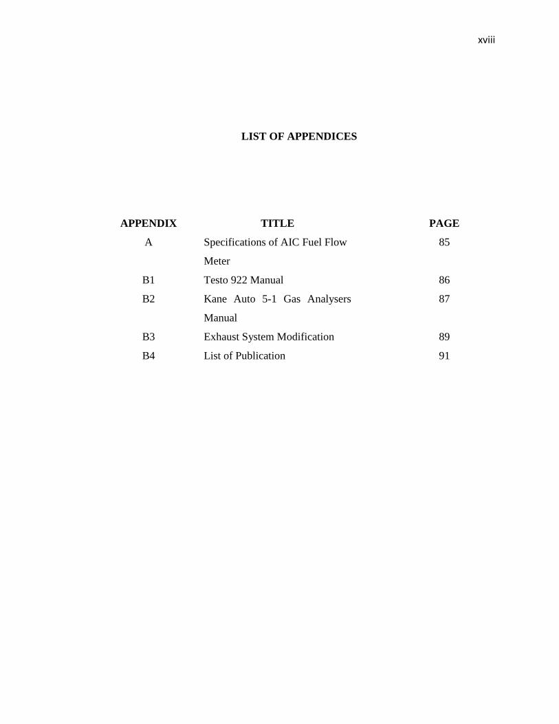
LIST OF APPENDICES
APPENDIX TITLE PAGE
A Specifications of AIC Fuel Flow
Meter
85
B1 Testo 922 Manual 86
B2 Kane Auto 5-1 Gas Analysers
Manual
87
B3 Exhaust System Modification 89
B4 List of Publication 91

CHAPTER 1
INTRODUCTION
1.1 Background of Study
Air pollution has been known to be a major risk to health and environment. Outdoor
air pollution is estimated to cause 1.3 million annual deaths worldwide
(WHO, 2011). All over the world, mobile sources stand out as the largest
contributors of a number of air pollutants which produced about 70 to75 % of the
total air pollutions.
One automobile exhaust can release gas that contains nearly 200 different
components into the atmosphere (Mishakov, 2011). The emission potential of
gasoline-powered vehicles are carbon monoxide (CO, 0.5 vol.%), unburned
hydrocarbons (HC, 350 ppm), nitrogen oxide (NOx, 900 ppm), hydrogen (H2, 0.17
vol.%), water (H2O, 10 vol.%), carbon dioxide (CO2, 10 vol.%), and oxygen (O2, 0.5
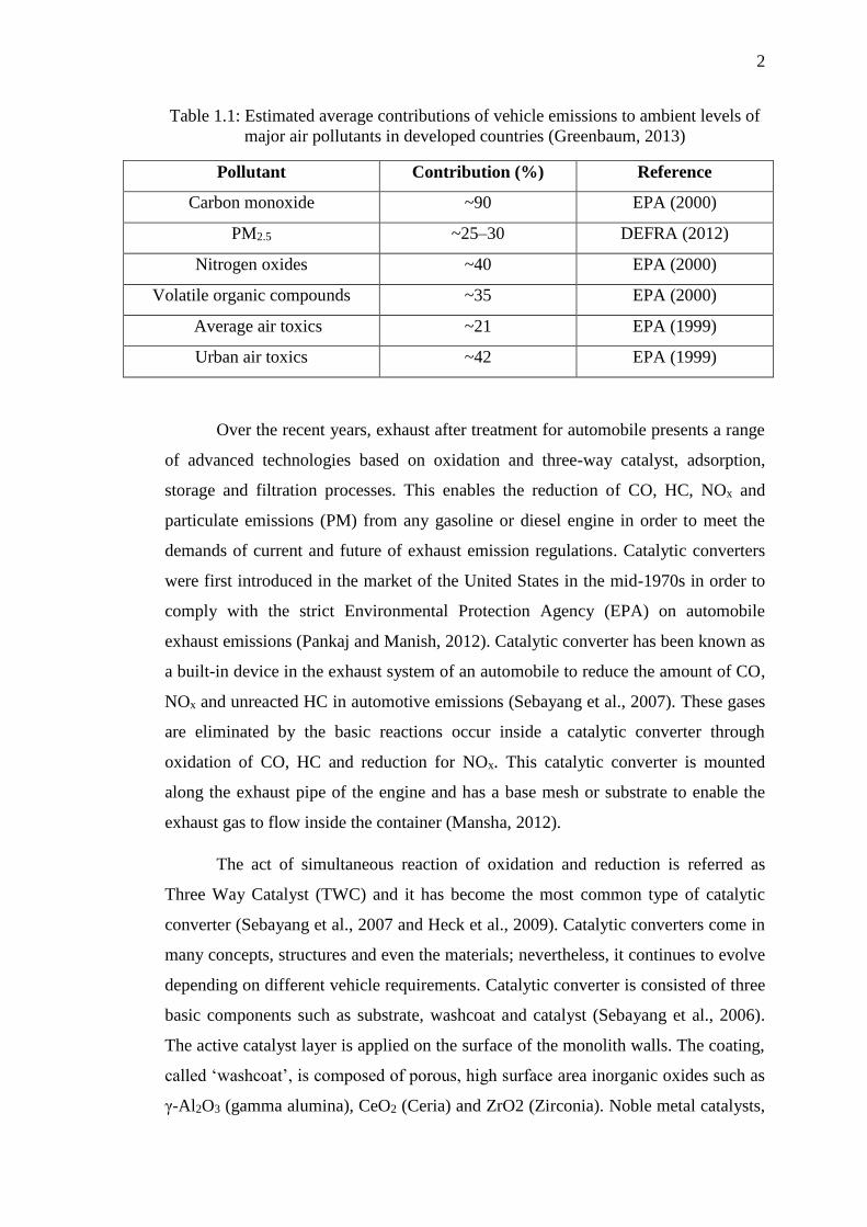
vol.%) (Bharat and Kuldeep, 2012). Table 1.1 shows the estimated average
contributions of vehicle emissions of major air pollutants.
2
Table 1.1: Estimated average contributions of vehicle emissions to ambient levels of
major air pollutants in developed countries (Greenbaum, 2013)
Pollutant Contribution (%) Reference
Carbon monoxide ~90 EPA (2000)
PM2.5 ~25–30 DEFRA (2012)
Nitrogen oxides ~40 EPA (2000)
Volatile organic compounds ~35 EPA (2000)
Average air toxics ~21 EPA (1999)
Urban air toxics ~42 EPA (1999)
Over the recent years, exhaust after treatment for automobile presents a range
of advanced technologies based on oxidation and three-way catalyst, adsorption,
storage and filtration processes. This enables the reduction of CO, HC, NOx and
particulate emissions (PM) from any gasoline or diesel engine in order to meet the
demands of current and future of exhaust emission regulations. Catalytic converters
were first introduced in the market of the United States in the mid-1970s in order to
comply with the strict Environmental Protection Agency (EPA) on automobile
exhaust emissions (Pankaj and Manish, 2012). Catalytic converter has been known as
a built-in device in the exhaust system of an automobile to reduce the amount of CO,
NOx and unreacted HC in automotive emissions (Sebayang et al., 2007). These gases
are eliminated by the basic reactions occur inside a catalytic converter through
oxidation of CO, HC and reduction for NOx. This catalytic converter is mounted
along the exhaust pipe of the engine and has a base mesh or substrate to enable the
exhaust gas to flow inside the container (Mansha, 2012).
The act of simultaneous reaction of oxidation and reduction is referred as
Three Way Catalyst (TWC) and it has become the most common type of catalytic
converter (Sebayang et al., 2007 and Heck et al., 2009). Catalytic converters come in
many concepts, structures and even the materials; nevertheless, it continues to evolve
depending on different vehicle requirements. Catalytic converter is consisted of three
basic components such as substrate, washcoat and catalyst (Sebayang et al., 2006).
The active catalyst layer is applied on the surface of the monolith walls. The coating,
called ‘washcoat’, is composed of porous, high surface area inorganic oxides such as
γ-Al2O3 (gamma alumina), CeO2 (Ceria) and ZrO2 (Zirconia). Noble metal catalysts,

3
such as Platinum (Pt), Palladium (Pd) and Rhodium (Rh), are deposited on the
surface and within the pores of the washcoat (Pontikakis, 2003).
In the last few years, the monolith or honeycomb structure catalyst has been
the most dominant catalyst used for gasoline engine. This type of catalyst is a
mixture of alkaline earth-metals, oxides and platinum group elements (PGEs) such as
Pt, Pd and Rh in which are all coated with highly porous washcoat of 90% γ-Al2O3
(Paraskevas, 2012). Ceramic and metallic substrates are the most common catalytic
converter used in regard to the catalyst type (Kaspar et al., 2003). In spite of extruded
ceramic monoliths being the most widely used substrate material, mainly because of
its relatively low manufacturing costs, foil metallic monolith substrates has become
more advanced in after-treatment market. It is selected as the substrate due to its
high thermal conductivity, lower heat capacity, greater thermal and mechanical shock
resistant, thinner wall lower pressure drop (Wu et al., 2005), higher coefficient of
thermal expansion (CTE) (Zhao et al., 2003) high temperature oxidation resistance
and is able to achieve larger specific surface area as shown in Figure 1.1.
As many researchers have been focused on the modeling and characterization
of the catalytic converter, there is a need for experimental testing on both ceramic
and metallic converters. In this project, the experimental measurement of exhaust
emission of both ceramic and metallic catalytic converter were compared in order to
examine the conversion efficiency of the exhaust gases in respond to the real engine
operating conditions such as engine speed and load.
Figure 1.1: Catalytic converter monolith of (1) ceramic and (2) metallic material
(Putrasari et al., 2010).

4
1.2 Problem Statement
The contribution of exhaust emissions reduction via sophisticated engine system is
relatively limited; however, increased environmental awareness has led to the
demand for products and processes which are more compatible with the environment
(Hasan, 2011). The most common type of after treatment used for the petrol engine is
the ‘three-way catalyst’ (TWC) which caters for a simultaneous oxidation and
reduction of exhaust gas components. Ceramic and metallic catalytic converters are
the most commonly used products available in the exhaust after treatment market
(Bode, 2002). There have been a vastly increased interest in experimental studies that
investigated the performance of the catalytic converters. Martin et al. (1998) has
experimentally investigated the effects of flow distribution, space velocity and light-
off temperature on the performance of catalytic converters. Buchner et al. (2001)
have gathered an experimental data base from test bench and dynamometer in order
to determine the heat transfer coefficients in catalytic converters. Silva et al. (2006)
evaluated the conversion efficiency of a catalytic converter under steady operating
condition. The inlet and outlet chemical species concentration, temperature and air
fuel ratio (A/F) were measured as a function of the brake mean effective pressure
(BMEP) and engine speed (rpm). Pannone and Mueller (2001) and Santos and Costa
(2008) have compared catalyst system using ceramic and metallic substrates in order
to assess the influence of various substrate parameters on the exhaust gas conversion
efficiencies. Despite that, there is still lack of literature on the exhaust gas conversion
data for different catalyst types for two different gasoline fuels (RON 95 and RON
97).
Thus, the present study attempts to analyze the performance of the ceramic
and metallic catalytic converter on its conversion efficiency. Ceramic and metallic
three way catalytic converter have been compared to assess the influence of physical
parameters and fuel properties on the engine parameters and exhaust gas conversion
for several different operating conditions. The inlet and outlet chemical species
concentration and temperature were measured as a function of the engine speed
(rpm).
5
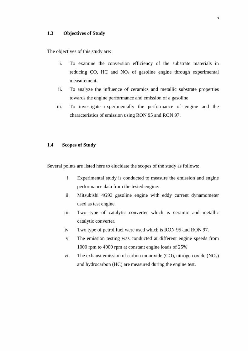
1.3 Objectives of Study
The objectives of this study are:
i. To examine the conversion efficiency of the substrate materials in
reducing CO, HC and NOx of gasoline engine through experimental
measurement.
ii. To analyze the influence of ceramics and metallic substrate properties
towards the engine performance and emission of a gasoline
iii. To investigate experimentally the performance of engine and the
characteristics of emission using RON 95 and RON 97.
1.4 Scopes of Study
Several points are listed here to elucidate the scopes of the study as follows:
i. Experimental study is conducted to measure the emission and engine
performance data from the tested engine.
ii. Mitsubishi 4G93 gasoline engine with eddy current dynamometer
used as test engine.
iii. Two type of catalytic converter which is ceramic and metallic
catalytic converter.
iv. Two type of petrol fuel were used which is RON 95 and RON 97.
v. The emission testing was conducted at different engine speeds from
1000 rpm to 4000 rpm at constant engine loads of 25%
vi. The exhaust emission of carbon monoxide (CO), nitrogen oxide (NOx)
and hydrocarbon (HC) are measured during the engine test.

6
1.5 Significant of Study
The significant of this research are:
i. The outcome of this research is expected to contribute in the development
of ceramic and metallic substrate.
ii. The intent is to further clarify the performance of metallic and ceramic
substrates under different engine conditions.
1.6 Thesis Organization
This thesis consists of several chapters which contain different discussion as follows:
Chapter 1: Consists of the background of the study, problem statement,
research objectives, significant research, expected results and scope or limitation of
the project.
Chapter 2: Review about the terminology of catalytic converter, the
development material and method for developing catalytic converter and the
experimental studies from the past research.
Chapter 3: Described the current method and material used in this research
and also the analysis and equipment used to achieve the research objectives.
Chapter 4: Discuss a result of the experimental result of exhaust emission
testing in order for determining the effectiveness of the new catalyst and technique
approach applied in this project.
Chapter 5: Consist of conclusions of this research which answer the
objectives and also recommendation to continue this research for the next researcher.

CHAPTER 2
LITERATURE REVIEW
2.1 Introduction
This chapter presents overview of regulation of vehicle emission standard and the
theoretical background and previous research related to the component of catalytic
converter and its development in after treatment application. It discusses on the
development of ceramics and metallic substrate and its properties in which affect the
overall performance of the catalytic converter in reducing the vehicle exhaust
emission.
2.2 Regulation of Vehicles Emission
Automobile emission has always been a major source of atmospheric pollution.
Kaspar et al., (2003) suggested that automobile exhaust composition is depended on
a variety of factors such as type of engine, driving conditions and vehicle speed. The
creation of pollutants may result from a number of chemical changes that take place
from the mixture of hydrocarbons or gasoline and air which is ignited through
combustion process (Kaleli, 2003). In the 20th century, the pollutants released from
internal combustion engines had raised serious health and environmental issues
(Seinfeld, 2004). In response to this concern, a stringent legislation regulating
emissions has been developed in many countries. Table 2.1 shows the current

8
summary of the California emission standard for passenger cars which involve
Transitional Low Emission Vehicle (TLEV), Low Emission Vehicle (LEV), Ultra
Low Emission Vehicle (ULEV) and Zero Emission Vehicle (ZEV).
Table 2.1: California emission standard for passenger cars (EPA, 2000)
Category Durability Basis
(miles)
NMOG
(g/mile)
CO (g/mile) NOx
(g/mile)
TLEV 50, 000
120, 000
0.125
0.156
3.4
4.2
0.4
0.6
LEV 50, 000
120, 000
0.075
0.09
3.4
4.2
0.05
0.07
ULEV 50, 000
120, 000
0.04
0.055
1.7
2.1
0.05
0.07
ZEV -0- -0- -0- -0-
The Environmental Protection Agency (EPA) has established a vehicle test
procedure namely the Federal Test Procedure (FTP) which stimulates the average of
the driving conditions of vehicles in the United State where the pollutant emission
gases such as CO, NOx and unburned HC are measured and analysed. The FTP cycle
is conducted by attaching a dynamometer to a vehicle. The FTP test also measure
gases emitted from vehicle exhaust during conditions such as cold start conditions,
hot start and combination of urban and highway driving conditions (Heck and
Farrauto, 2009). The United State (U.S) and the European Union (E.U) have different
specification for vehicle emission control in terms of test cycle conducted to the
vehicles, fuel quality and type of pollutants as shown in Table 2.2.
9
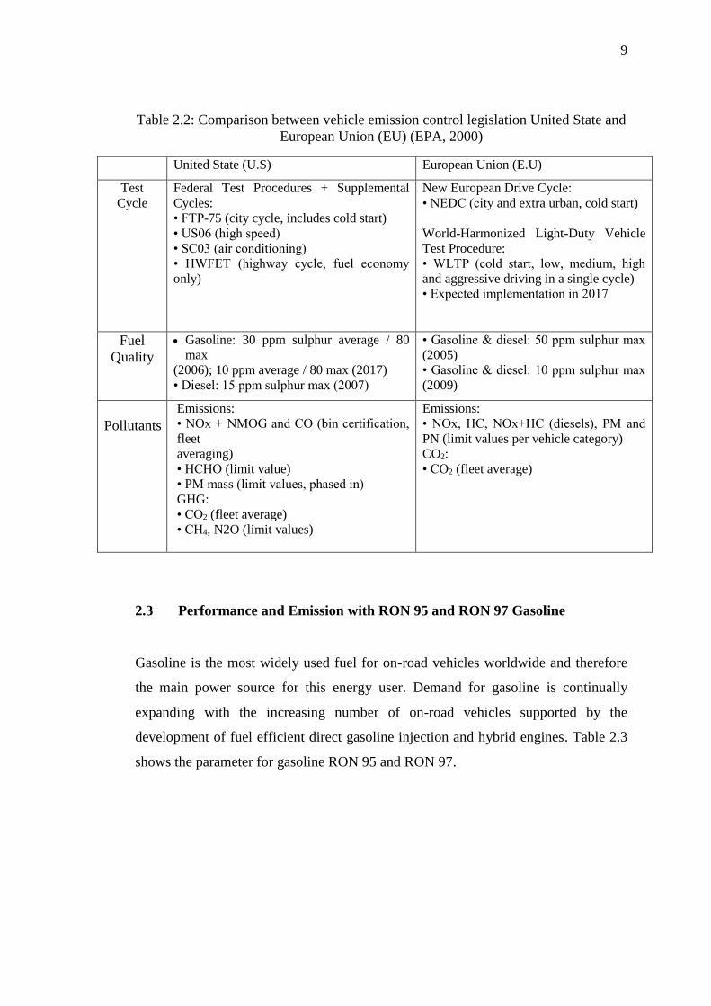
Table 2.2: Comparison between vehicle emission control legislation United State and
European Union (EU) (EPA, 2000)
United State (U.S) European Union (E.U)
Test
Cycle
Federal Test Procedures + Supplemental
Cycles:
• FTP-75 (city cycle, includes cold start)
• US06 (high speed)
• SC03 (air conditioning)
• HWFET (highway cycle, fuel economy
only)
New European Drive Cycle:
• NEDC (city and extra urban, cold start)
World-Harmonized Light-Duty Vehicle
Test Procedure:
• WLTP (cold start, low, medium, high
and aggressive driving in a single cycle)
• Expected implementation in 2017
Fuel
Quality
Gasoline: 30 ppm sulphur average / 80
max
(2006); 10 ppm average / 80 max (2017)
• Diesel: 15 ppm sulphur max (2007)
• Gasoline & diesel: 50 ppm sulphur max
(2005)
• Gasoline & diesel: 10 ppm sulphur max
(2009)
Pollutants
Emissions:
• NOx + NMOG and CO (bin certification,
fleet
averaging)
• HCHO (limit value)
• PM mass (limit values, phased in)
GHG:
• CO2 (fleet average)
• CH4, N2O (limit values)
Emissions:
• NOx, HC, NOx+HC (diesels), PM and
PN (limit values per vehicle category)
CO2:
• CO2 (fleet average)
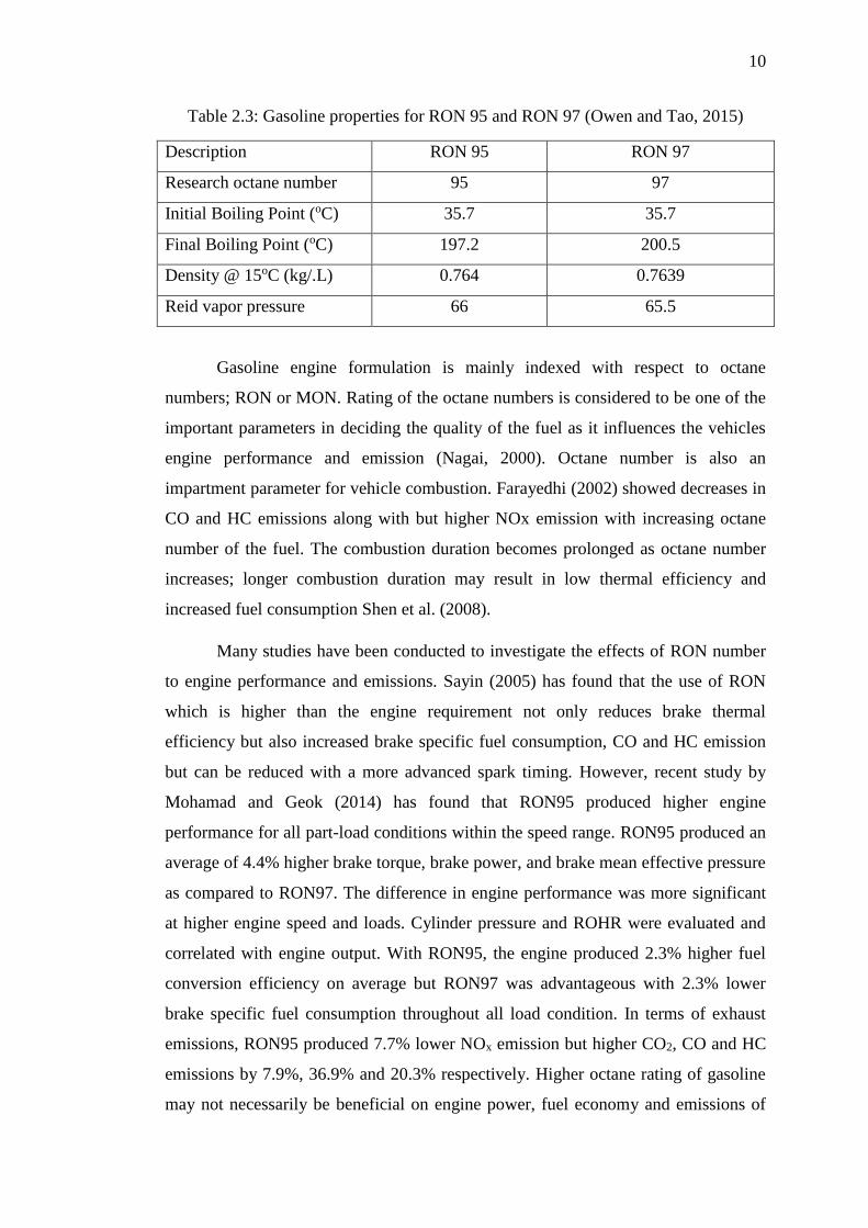
2.3 Performance and Emission with RON 95 and RON 97 Gasoline
Gasoline is the most widely used fuel for on-road vehicles worldwide and therefore
the main power source for this energy user. Demand for gasoline is continually
expanding with the increasing number of on-road vehicles supported by the
development of fuel efficient direct gasoline injection and hybrid engines. Table 2.3
shows the parameter for gasoline RON 95 and RON 97.
10
Table 2.3: Gasoline properties for RON 95 and RON 97 (Owen and Tao, 2015)
Description RON 95 RON 97
Research octane number 95 97
Initial Boiling Point (oC) 35.7 35.7
Final Boiling Point (oC) 197.2 200.5
Density @ 15oC (kg/.L) 0.764 0.7639
Reid vapor pressure 66 65.5
Gasoline engine formulation is mainly indexed with respect to octane
numbers; RON or MON. Rating of the octane numbers is considered to be one of the
important parameters in deciding the quality of the fuel as it influences the vehicles
engine performance and emission (Nagai, 2000). Octane number is also an
impartment parameter for vehicle combustion. Farayedhi (2002) showed decreases in
CO and HC emissions along with but higher NOx emission with increasing octane
number of the fuel. The combustion duration becomes prolonged as octane number
increases; longer combustion duration may result in low thermal efficiency and
increased fuel consumption Shen et al. (2008).
Many studies have been conducted to investigate the effects of RON number
to engine performance and emissions. Sayin (2005) has found that the use of RON
which is higher than the engine requirement not only reduces brake thermal
efficiency but also increased brake specific fuel consumption, CO and HC emission
but can be reduced with a more advanced spark timing. However, recent study by
Mohamad and Geok (2014) has found that RON95 produced higher engine
performance for all part-load conditions within the speed range. RON95 produced an
average of 4.4% higher brake torque, brake power, and brake mean effective pressure
as compared to RON97. The difference in engine performance was more significant
at higher engine speed and loads. Cylinder pressure and ROHR were evaluated and
correlated with engine output. With RON95, the engine produced 2.3% higher fuel
conversion efficiency on average but RON97 was advantageous with 2.3% lower
brake specific fuel consumption throughout all load condition. In terms of exhaust
emissions, RON95 produced 7.7% lower NOx emission but higher CO2, CO and HC
emissions by 7.9%, 36.9% and 20.3% respectively. Higher octane rating of gasoline
may not necessarily be beneficial on engine power, fuel economy and emissions of

11
polluting gases. Even though RON97 proves to be beneficial in terms of emission
reduction of CO2, CO and HC, the price is 38% higher and higher NOx emission is
more expensive in the long run.
2.4 Emission of Gasoline Engine
Emission of gasoline engine has been known as a major source of air pollution along
urban traffic routes in developed countries. In Malaysia, it was estimated that nearly
51% from 12 milions of registered vehicles used gasoline engine (Kalam, 2011).
Generally, gasoline engines are referred to as internal combustion engine (ICE)
where initiation of the combustion process of air–fuel mixture is ignited within the
combustion chamber which is done either by spark ignition (SI) or compression
ignition (CI) (Bera, 2010) . Emission from gasoline engine can be reduced through
improvement of engine design, combustion conditions and catalytic after treatment
devices (Faiz, 2006). Table 2.4 listed the common gasoline exhaust gas composition
at different operating condition.
Table 2.4: Typical exhaust gas compositions at the common gasoline engine
operating conditions ( GM Research& Development, 2006)
Gas Cold-Start Warm-up
CO 0.2 to 6% (̴ 1.5 % avg.) ̴ 0.8 % avg.
HC 400 to 1200 ppm (C3) ( ̴650 ppm avg.) ̴450 ppm (C 3) avg.
H2 1/3 CO 1/3 CO
NO 100 to 1200 ppm (̴ 500 ppm avg.) ̴500 ppm avg.
O2 0.5 ̴ 2.5% (̴1.2 % avg.) ̴0.7% avg.
SO2 20 ppm or lower 20 ppm or lower
2.4.1 Emission of Nitrogen Oxides (NOx)
Motor vehicles are usually the major sources of nitrogen oxides in urban areas. NOx
primarily is a mixture of nitric oxide (NO) and lesser quantities of nitrogen dioxide
(NO2). The NOx gases are formed by oxidation of nitrogen in air at high combustion
temperatures. When oxidised to NO2 in ambient air, NO plays a major role of the

12
formation of photochemical oxidants (such as ozone) and particles (such as nitrates).
Zhao et al., (2004) referred the reduction of NOx to nitrogen and oxygen caused by
temperature as thermal mechanism which derived the NO reaction under reducing
conditions as Eq. 2.1.
Nitrogen dioxide appears to exert its effects directly on the lung, leading to an
inflammatory reaction on the surfaces of the lung (Streeton, 1997).
2.4.2 Emission of Carbon Monoxide (CO)
CO is a product of incomplete combustion, which simply means that there was a lack
of oxygen for burning when the combustion process took place (Kaleli, 2003). The
conversion of CO is as Eq. 2.2 (Kaspar et al., 2003):
2CO + O2 ↔ 2CO2 (2.2)
CO is a highly toxic, colourless, odourless gas that is dangerous to those who
inhale it. This is because CO has a high affinity to blood, and when inhaled, it
combines with the haemoglobin in blood to produce carboxyl haemoglobin, which is
an extremely toxic substance (Narendran, 2013).
2.4.3 Emission of Hydrocarbon (HC)
Hydrocarbons react in the presence of nitrogen oxides and sunlight to form ground-
level ozone, a major component of smog. It is our most widespread and intractable
urban air pollution problem. A number of exhausts HC are also toxic, with the
potential to affect human health. HC includes many toxic compounds that cause
cancer and other adverse health effects (WHO, 2003). The conversion of HC gas is
shown as in Eq. 2.3:
CxH4x + 2xO2 → xCO2 + 2xH2O (2.3)
2NOx → xO2 + N2 (2.1)

13
2.5 Emission Standard of Gasoline Engine
Every country has its own strict regulation for vehicle emissions which are varied
significantly. In 2005, the first major reductions in all emitted pollutants are gained
by electronic optimization of the combustion process when gasoline-powered vehicle
is restricted to emitting between 1% to 3% CO of a comparable size unit in 1970
(Martyr and Plint, 2012). The United States (US) and European Union (EU)
regulation standards have been recognized and used worldwide. Table 2.5 presented
the comparison of EU Vehicle Emission Standard in ASEAN countries while Figure
2.1 illustrates the EU emission standard for exhaust emission gases of HC and CO for
gasoline powered vehicles.
Table 2.5: Light Duty Vehicles (LDVs) Emission Standard in ASEAN countries
(Silitonga et al., 2012)

14
Since Euro 1, vehicles have to be tested for emission not only to gain type
approvals new vehicles, but also after a number of miles in service. EU recently state
that the original equipment manufacturer (OEM) is responsible for assuring that
vehicles meet emission standard for 80,000 kilometers, in the US which the rules use
160,000 km.
2.6 Factors Affecting Exhaust Emission
Consideration of several variables and parameters can control exhaust emission. A
complete combustion in engine cylinder is needed in order for the engine to work
efficiently. Barry (2006) stated that in order to ensure a complete combustion in an
engine, several matters such as the accurate amount of air and fuel must be mixed
with the correct amount of heat at the correct time. These two factors, air-to fuel ratio
and cold-start seems to be the most important factors that could affect exhaust
emission.
Figure 2.1: European Carbon Monoxide (CO) and hydrocarbon (HC) emission standards
for gasoline light passenger cars (EPA,2000)

15
2.6.1 Air-To-Fuel Ratio
The air-fuel ratio is known as the mass ratio of air to gasoline, which is required to
ensure the operation of injection system of an engine (Halderman, 2012). The
emission of pollutant can be caused by improper ratio of air to fuel during the
combustion process. Thus, it is important to ensure a correct air-fuel ratio in order to
control the exhaust emission, good drivability and prevention internal damage of
engine parts (Barry, 2006). All three pollutants can be converted (essentially
equilibrated to CO2, H2O and N2) with high efficiency over a single catalyst if the
air–fuel ratio can be controlled sufficiently close to the stoichiometric value. Figure
2.2 shows the illustration of the total effect of the air-fuel ratio on engine emission.
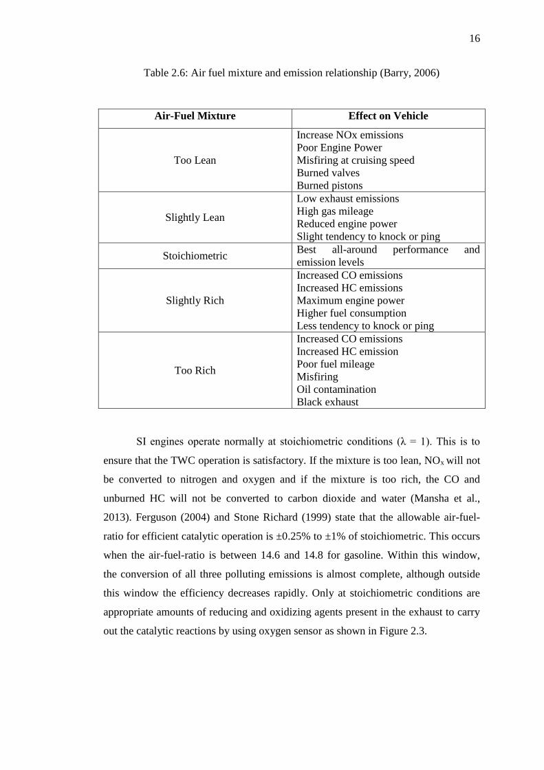
Table 2.6 list the relationship between the air-fuel-ratio condition and its effect on the
emission gases.
Figure 2.2: Air-fuel-ratio for exhaust SI gasoline emission (Heywood, 1998)
16
Table 2.6: Air fuel mixture and emission relationship (Barry, 2006)
Air-Fuel Mixture Effect on Vehicle
Too Lean
Increase NOx emissions
Poor Engine Power
Misfiring at cruising speed
Burned valves
Burned pistons
Slightly Lean
Low exhaust emissions
High gas mileage
Reduced engine power
Slight tendency to knock or ping
Stoichiometric Best all-around performance and
emission levels
Slightly Rich
Increased CO emissions
Increased HC emissions
Maximum engine power
Higher fuel consumption
Less tendency to knock or ping
Too Rich
Increased CO emissions
Increased HC emission
Poor fuel mileage
Misfiring
Oil contamination
Black exhaust
SI engines operate normally at stoichiometric conditions (λ = 1). This is to
ensure that the TWC operation is satisfactory. If the mixture is too lean, NOx will not
be converted to nitrogen and oxygen and if the mixture is too rich, the CO and
unburned HC will not be converted to carbon dioxide and water (Mansha et al.,
2013). Ferguson (2004) and Stone Richard (1999) state that the allowable air-fuel-
ratio for efficient catalytic operation is ±0.25% to ±1% of stoichiometric. This occurs
when the air-fuel-ratio is between 14.6 and 14.8 for gasoline. Within this window,
the conversion of all three polluting emissions is almost complete, although outside
this window the efficiency decreases rapidly. Only at stoichiometric conditions are
appropriate amounts of reducing and oxidizing agents present in the exhaust to carry
out the catalytic reactions by using oxygen sensor as shown in Figure 2.3.

17
Figure 2.3: Response of oxygen sensor used in exhaust pipeline
(Farrauto and Heck, 1999)
2.6.2 Cold-Start Condition
Cold start condition in engine plays an important role in producing exhaust emission.
Cold start or unstable engine running period is the time period required for the
catalyst to reach its light-off temperature (Raja and Arasu, 2015). Favez et al., (2009)
define cold start as emission in SI engine that begin after a minimum halt time of 12
hours or more. During cold start condition, CO and HC are emitted in large quantities
in the first few minutes after the spark ignition (SI) of the engine due to less active or
inactive catalytic converter (Iliyas et al., 2007). It has been found that the conversion
efficiency in catalytic converter is more effective only after the catalyst reaches
above 150 ̊C, which is the light-off temperature (Singer et al., 1999).
18
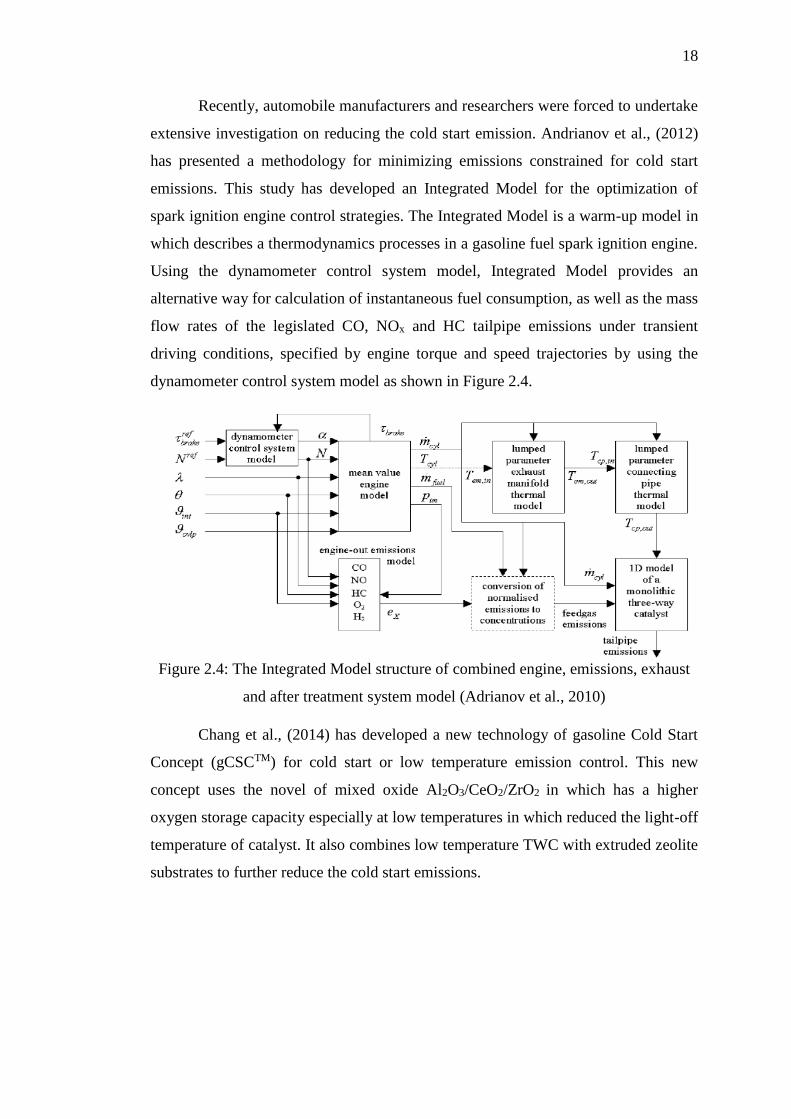
Recently, automobile manufacturers and researchers were forced to undertake
extensive investigation on reducing the cold start emission. Andrianov et al., (2012)
has presented a methodology for minimizing emissions constrained for cold start
emissions. This study has developed an Integrated Model for the optimization of
spark ignition engine control strategies. The Integrated Model is a warm-up model in
which describes a thermodynamics processes in a gasoline fuel spark ignition engine.
Using the dynamometer control system model, Integrated Model provides an
alternative way for calculation of instantaneous fuel consumption, as well as the mass
flow rates of the legislated CO, NOx and HC tailpipe emissions under transient
driving conditions, specified by engine torque and speed trajectories by using the
dynamometer control system model as shown in Figure 2.4.
Figure 2.4: The Integrated Model structure of combined engine, emissions, exhaust
and after treatment system model (Adrianov et al., 2010)
Chang et al., (2014) has developed a new technology of gasoline Cold Start
Concept (gCSCTM) for cold start or low temperature emission control. This new
concept uses the novel of mixed oxide Al2O3/CeO2/ZrO2 in which has a higher
oxygen storage capacity especially at low temperatures in which reduced the light-off
temperature of catalyst. It also combines low temperature TWC with extruded zeolite
substrates to further reduce the cold start emissions.

19
2.6.3 Exhaust Temperature
Exhaust gas temperature is the indication of the combustion quality in the
combustion chamber (Sureshkumar et al., 2008). The exhaust of vehicles gas
temperature may vary from 300oC to 400oC from idling to around 900oC at full load
condition in internal combustion engine. However, the common temperature of
exhaust gas lies between 400oC to 600oC. It requires lower temperature for unburned
HC to be oxidizing compare for the oxidation of CO in which normally oxidizes at a
specific residence time (Mansha et al., 2012). Without having a catalyst for the
conversion of pollutant gases, the temperature in the exhaust pipeline will exceed
600oC and the residence time to oxidize HC is greater than 50ms while the
temperature that are required to oxidize CO is more than 700oC (Heywood, 1988).
Temperature in the catalytic warm-up also plays a vital role for the oxidation
of the gases. In reference to the previous research, Ferguson (2004) states that the
conversion will be efficient at fully warmed up catalytic conditions about 98% to
99% for CO and 95% for unburned HC depending on HC components. Willard
(2003) state that at temperature of 400oC or higher, the catalytic converter is fully
warmed up and will eliminate about 98-99% of CO, 95% of NOx and more than 95%
of unburned HC from the engine out exhaust. Conversion process in the catalytic
does not occur at NOx, CO and unburned HC is not observed. The rate of oxidation
of CO and HC increases and NOx decreases as exhaust gasses increases. 50%
conversion efficiency is referred as light off of catalyst (Mansha et al., 2013).
2.7 Catalytic Converter
Catalytic converter is a stainless steel container mounted along the exhaust pipe of
the engine that incorporates a honeycomb monolith made of ceramic or metal
(Ganesan, 2004). Today, most vehicles with gasoline-fuelled engines achieve the
emissions limits by using the three-way catalysts, which are installed a part of the
exhaust system. These devices are designed to convert CO, NOx and HC engine-out
emissions to much less harmful CO2, H2O and N2 as shown in Figure 2.5.

20
Figure 2.5: Schematic view of three way catalyst converter (Zi et al., 1996)
Catalytic Converters are important post combustion after treatment devices
mounted in the exhaust system of engines to reduce the engine exhaust emissions and
are classified as either Two-Way or Three-Way. Two-Way Catalytic Converter
(2WCC) works on two gases, CO and unburned HC while the NOx is controlled
though exhaust gas recirculation (EGR) by retarding the ignition timing (Mansha et
al., 2013). A catalytic converter is consisted of three basic components, which are
substrate, washcoat and catalyst (Sebayang et al., 2009).
The Three-Way Catalytic Converter (TWCC) will convert all the three
gaseous pollutant that are mainly CO, unburned HC and NOx. TWCC typically
contains active catalytic materials of Pt, Rh and Pd, which promote the oxidation of
CO and unburned HC and reduction of NOx. Pt and Pd are functioning as an
oxidation catalyst while Rh (Rhodium) act as a reducing catalyst for NOx reduction
(Kamble et al., 2008).
The efficient conversion of CO, unburned HC and NOx are simultaneously
carried out on the same catalyst bed. The maximum conversion efficiency can be
achieved by operating the engine near stoichiometric condition through precise
control of A/F ratio mixture. The TWCC is at most efficient when the exhaust gas
composition from the engine is cycling around stoichiometric conditions. A ceramic
or metallic honeycomb monolithic substrate, particularly cylindrical or oval shaped)
is the common option for most environmental applications that requires high flow
rates and low pressure drop (Santos, 2007).

21
2.7.1 Subtrate
Monolithic substrate supports are uni-body structures composed of interconnected
repeating cells or channels. They are most commonly composed of ceramic or metal
materials but some can also be made of plastic (Heck et al.,2002) as shown in Figure
2.6. The monolith parts itself can be produced in a number of sizes and shapes,
typically round or oval cross-sectional areas for automotive applications, or square
for stationary emission uses. Cross-sectional part diameters for single pieces up to 35
cm have been produced commercially for heavy duty vehicle uses.
The honeycomb or also called “catalyst support” are capable to support the
catalyst as it can increase the amount of surface area (Mizanuzzaman et al., 2013). In
mid 1970s, the United States has been the first country to use ceramic substrates
(Heck and Farrauto, 1995). Each ceramic monolith is coated with a washcoat and a
catalyst coating made from precious metal.
In the automotive and stationary emission control area, monolith substrate is a
common component that is used for selective catalytic reduction (SCR) of nitrogen
oxides. Thus, the usage of the monolith substrates is increasingly used under
Figure 2.6: Ceramic and metallic monolith (Heck et al., 2002)

22
development and for evaluation in new reactor application such as ozone abatement,
chemical process system, refining industries and other types of industries usage as
(Jimme, 2001). The manufacturing of monolith substrate consists of several steps
that need to be followed by referring the flow in Figure 2.7.
Figure 2.7: Fabrication of monolith honeycomb substrates (Jimme, 2001)
For the first steps, the raw materials need to undergo mixing process where
the materials are mixed in the binder. The result of the mixing process is continued
with the second steps, the plasticizing steps where the raw materials are plasticized
with solvent, which is usually water. The plasticizing step requires the materials to
undergo extrusion process (Jimme, 2001). The extrusion processes usually use
unique dies to fabricate monolith structure. After extrusion process, the monolith
substrate will be dried at elevated temperature in order to ensure that moisture
elimination is done without cracking the monolith substrates. In the final steps, the
component will undergo firing steps; the monolith is placed at elevated temperature
to complete the solid-state reactions and to obtain the desired physical condition of
the complete monolith substrates. The monolith type substrate has been widely used
due to the catalyst coating method, flexibility in reactor design, low pressure drop
and high heat and mass transfer (Nijhuis, 2001).
2.7.2 Washcoat
The washcoat is a type of ceramic layer (oxide layer) with specific surface area and
acts as a support for catalyst materials. The waschoat also acts as a barrier from high
temperature corrosion (Cueff et al., 2004). Alumina (Al2O3) is one of the most

23
applied washcoat materials (Heck, et al., 2009). The washcoat is a thin layer of
alumina (Al2O3) coating, typically 20-150 μm thick with a high surface area on the
top of substrate. Cross section image of the coating, called ‘washcoat’ is composed of
porous, high surface area inorganic oxides such as γ-Al2O3 (gamma alumina), CeO2
(Ceria) and ZrO2 (Zirconia). Alumina is chosen due to its high surface area and
relatively good thermal stability under the hydrothermal conditions of the exhausts
(Kaspar et al., 2003).
2.7.3 Catalyst
In the last few years, the most dominant catalyst for gasoline vehicles has been the
monolith or honeycomb structure catalyst. This catalyst is consisted of a skeleton
coated with highly porous washcoat of about 90% γ-Al2O3 and a mixture of alkaline-
earth metals, oxides and noble metals such as Pt, Pd and Rh which are fixed in the
washcoat surface as shown in Figure 2.8. Noble metal catalysts are deposited on the
surface and within the pores of the washcoat (Pontikakis, 2003).
2.8 Ceramic Catalytic Converter
Ceramics materials are mainly processed from clay products such as sewer tiles,
bricks for building usage, and sewer pipes. According to Keane (2003) ceramic is a
Figure 2.8: Washcoat and catalyst development focused area in catalytic
converter (Twigg, 2007).

24
combination between non-metallic and metallic elements such as Alumina Oxide
(Al2O3) Calcium Oxide (CaO) and Silicon Nitride (Si3N4). Advanced ceramic
production includes structural materials used for engine components, machining
cutting tools and bio-ceramics for hospitality usage such as tooth and bone
replacements. Ceramic has wide range of application areas and catalysis of catalytic
converter is one of it (Hart el al., 1989).
Ceramic has high potential in withstanding high temperatures, exhibit
chemical durability and wear resistance in which is suitable for catalytic use for
various operating conditions. The applications of ceramic can be divided into
catalysts usage and materials support such as substrates to diffuse a variety of active
metals. The investigation had been made on direct synthesis and stabilization of
nano-crystalline ceramic materials for automobiles catalytic usage. Nano powders
fabrication from ceramic improved the properties of the materials, resulting in
production of advanced nanophase materials which may conduct heat, electrons and
ions more efficient compared to conventional materials.
The application of ceramic materials in ceramic substrates for automobiles
exhaust component possesses a large surface area for gas conversion process that
improves the efficiency of pollutant gases filtering and also acts as good thermal
shock resistance. It is one of the important components in conversion process in term
of performance balancing, pressure drop and maintaining strength of catalytic
materials. Ceramic substrates in commonly manufactured with honeycomb structures
which has high mechanical strength with low thermal expansion coefficient shown in
Figure 2.9.
Figure 2.9: Honeycomb structure of ceramic substrates in three dimensional
(Keane, 2003)

REFERENCES
Al-Farayedhi, A.A. (2002). Effects of octane number on exhaust emissions of a
spark ignition engine. Int. J. Energy Res., 26: 279-89. DOI: 10.1002/er.783
Andrianov,D., Keynejad F., Dingli, R. and Voice G. (2010). A Cold-Start
Emissions Model of an Engine and Aftertreatment System for Optimisation
Studies. SAE Technical Paper 2010-01-1274.
Artelt, S., Kock, H., König, H., Levsen, K., Rosner, G. (1999). Engine
dynamometer experiments: platinum emissions from differently aged three-
way catalytic converters. Atmospheric Environment 33,pp. 3559-3567.
Bharat, S.P., Kuldeep, D, Patel. (2012). A Review paper on Catalytic
Converter for Automotive Exhaust Emission. International Journal of
Applied Engineering Research, ISSN 0973-4562 (7) (11)
Benson,M., Bennett, C.R., Harry, J.E., Patel, M.K. and M. Cross. (2000). The
Recovery Mechanism of Platinum Group Metals from Catalytic Converters
in Spent Automotive Exhaust Systems. Resources, Conservation and
Recycling, Vol. 31, No. 1, pp. 1-7.
Bera,P.B. and Hedge,M.S. (2010).Recent advances in auto exhaust catalysis.
Journal of the Indian Institute of Science. 90(2): 299-325
Bagus,I.R., Purwanto,P. and Hadiyanto,H. (2014). Optimum Design of
Manganese-Coated Copper Catalytic Converter to Reduce Carbon
Monoxide Emissions on Gasoline Motor . Procedia Environmental
Sciences. (23),pp. 86 – 92
76
Bu¨chner, S., Lardies, S.S, Degen A., Donnerstag A, Held W. (2001). A modular
numerical simulation tool predicting catalytic converter light-off by
improved modeling of thermal management and conversion characteristics.
SAE Paper 2001-01-0940
Chirag, A. and Rathod,P.P. (2013). Catalytic Converter Based On Non-Noble
Material. International Journal of Advanced Engineering Research and
Studies, (1) ,pp.118-120
Chakravarthy, V.K., Conklin, J.C., Daw, C..S. and D’Azevedo,E.F. (2003).
Application Catal. A: Gen. 241 (289)
Cueff,R., Buscail, H., Caudron, E., Riffard, F.,Issartel, C. and El Meski, S.
(2004). Effect of Reactive Element Oxide Coating on the High
Temperature Oxidation Behaviour of FeCrAl Alloys. Applied Surface
Science, 229( 1-4) , pp. 233-241.
Cash, T.F., Williams, J.L. and Zink, U.H. (1998). SAE Brazil Paper No. 982927.
Day J.P. and L.S. Socha. (1991). SAE Paper No. 910371.
Department Of Environment (DOE). (2009). Malaysia Environmental Quality
Report. Department of Environment, Ministry of Natural Resources and
Environment, Putrajaya.
US Environmental Protection Agency. (2000).Federal and California Exhaust and
Evaporative Emission Standards for Light-Duty Vehicles and Light-Duty
Trucks Printed on Recycled Paper. Washington, DC. Report EPA420-B-
00-001
Faiz, A.,Weaver,C.S.,and Walsh,,M.P. (2006).Air Pollution from Motor
Vehicles. Standards and Technologies for Controlling Emissions. The
World Bank Washington, D.C
Farrauto,R. J. and Heck R. M. (1995). Catalytic converters: state of the art and
perspectives. Vol. 51, Issues 3-4, pp. 351–360.
Favez, J.Y., Weilenmann, M., and Stilli, J. (2009). Cold start extra emissions as a
function of engine stop time: Evolution over the last 10 years, Atmospheric
Environment, 43, pp. 996-1007

77
Firdianto, A. (2012). Ultrasonic Treatment with Nickel Electroplating Combined
with Oxidation for Developing Gamma-Alumina Washcoat on Fe-Cr-Al
Substrate. Master Thesis. UniversitiTun Hussein Onn Malaysia, Malaysia
Final report for GM Research & Development. (2006). “Reaction Kinetics on
Modern Three-Way Catalysts”.
Franco, V., Kousoulidou, M., Muntean,M., Ntziachristos,L., Hausberger,S., and
Dilara,P.(2013). Road vehicle emission factors development: A review.
Atmospheric Environment ,70 (2013) ,pp.84-97
Ganesan, V. (2004). Internal Combustion Engines. Second Edition, USA:
McGraw Hill
Ghazikhani, M., Hatami, M., Safari, B., Ganji D.D. (2014). Experimental
investigation of exhaust temperature and delivery ratio effect on emissions
and performance of a gasoline–ethanol two-stroke engine. Case Study in
Thermal Engineering 2. Pp 82-90.
Greenbaum,D.S. (2013). Diesel and gasoline engine exhausts and some
nitroarenes. IARC Monogr Eval Carcinog Risks Hum, 105, pp. 49–62
Halderman, D. H. and Linder, J. (2012) . Automotive Fuel and Emissions Control
Systems. New Jersey, USA : Pearson
Hans Bode (2002). “Materials Aspects in Automotive Catalytic Converters.”
Germany: WILEY-VHC.
Hasan,O.A. (2011). Influence of Prototype Three Way Catalytic Converter on
Regulated and Unregulated Emissions from Gasoline HCCI/SI Engine.
Ph.D. Thesis. The University of Birmingham.
Hart,A. M. , Peters B. C. Plonka J. H., Werst Jr. and Macki J. M. (1989).
Advanced ceramic opportunities: a review. Chemical Engineering
Progress. Vol. 85. Pp 32-43.
Heck, R. M.,Farrauto, R. J. and Gulati, S. T. (2002). Catalytic Air Pollution
Control Commercial Technology, 3rd ed, John Wiley & Sons, ISBN 978 -0-
470-27503-0, New Jersey
78
Heck, R.M., Farrauto, R.J. and Gulati, S.T. (2009) . Catalytic Air Pollution
Control Commercial Technology. 3rd ed. USA: John Wiley & Sons, Inc
Heywood, J. B, (1998). Internal combustion engines fundamentals. USA:
McGraw-Hill Higher Education.
Hollembeak.,B. (2006).Automotive Fuel and Emissions. New York, USA :
Thomson Delmar Learning.
Iliyas, A., Zahedi-Niaki, M.H., Eic´, M., and Kaliaguine, S. (2007). Control of
hydrocarbon cold-start emissions: A search for potential adsorbents,
Microporous and Mesoporous Materials, 102: pp. 171-177.
Jimmie, L. W. (2001). Monolith structures, materials, properties and uses.
Catalyst today, Elsevier Science, pp 3-9.
Kaleli.,H.(2003).Engine emissions and poisoning effect of synthetic oil’s
additives on catalytic converter using an engine dynamometer ,Industrial
Lubrication and Tribology 55 (4) : pp. 162–177
Kamble, P. R and Ingle S. S. (2008). Copper Plate Catalytic Converter: An
Emission Control Technique, SAE number 2008-28-0104.
Kamil, M., Rahman, M.M, Bakar, R.A (2013). Integrated simulation model for
composition and properties of gases in hydrogen fueled engine.
International Journal of Automotive and Mechanical Engineering. Vol. 8,
pp. 1242-155, ISSN: 2229-8649.
Keane, M. A. (2003). Ceramics for catalysis. Journal Of Materials Science.
Volume 38, Issue 23, pp 4661–4675.
Klower, J., Kolb-Telieps, A., Bode, H., Brede, M., Lange, J., Brück, R. and
Wieres, L. (1998). Development of High-Temperature Corrosion Resistant
FeCrAl Alloys for Automotive Catalytic Converters. Materials Week
Congress for Innovative Materials, Processes, and Applications, Munich,
Germany :pp. 12-15
Kalam, M. and Masjuki H.. (2011). An experimental investigation of high
performance natural gas engine with direct injection. Energy, 36(5): 3563-
3571.

79
Kašpar.,J.,Fornasiero.P., and Hickey.,N. (2003). Automotive catalytic converters:
current status and some perspectives. Catalysis Today, 77,pp. 419–449.
Koltsakis, G.C. and Stamatelos, A.M. (1997). Catalytic Automotive Exhaust
After Treatment. Progress in Energy and Combustion Science, 23 (1), pp.
1-39.
Konstansas, G. and Stamelos.,A. (2004). Quality assurance of exhaust emissions
test data. Proc. Instn Mech. Engrs , 218 Part D: J. Automobile
Engineering.
Konya, S. (2006). Elastic-plastic Thermal Stress Analysis of Metal Substrates for
Catalytic Converters. Japan Scienec and Technology Agency. Issue 383,
pp 7-12.
Kolaczkowski, S. (2006). Treatment of Volatile Organic Carbon (VOC)
Emissions from Stationary Sources: Catalytic Oxidation of The Gaseous
Phase. In: Structured Catalysts and Reactors 2nd ed.
Macklin,D.N. and Hua Zhao. (2015). “High load performance and combustion
analysis of a four-valve direct injection gasoline engine running in the
two-stroke cycle” Applied Energy 159 (2015) 117– 131, Elsevier Ltd
Mansha, M., Qureshi, A. H., Chaudry, I . A., and Shahid, E. M. (2013). Three
Way Catalytic Simulation of Engine-Out Exhaust Emission .Journal of
Quality and Technology Management, 8, (I), pp.57 – 68
Mansha, M. Shahid. E.M. and Qureshi A.H. (2012). Control of Combustion
Generated Emissions from Spark Ignition Engines: A Review, Pakistan
Journal of Engineering and Applied Sciences, Vol. 11, pp 114-128
Martyr, A. J. and Plint., M. A. (2012). Engine Testing: The Design, Building,
Modification and Use of Powertrain Test Facilities. Butterworth
Heinemann. ISBN 10: 0080969496
Martin, AP, Will NS, Bordet A, Cornet P, Gondoin C, Mouton X. (1998). Effect
of flow distribution on emissions performance of catalytic converters.
SAE Paper 980936, 1998.

80
Mizanuzzaman.,M.,Dastidar.,A.G., Rony.,,M.R.U, Azam.R., and Mahmud.,M.A.
(2013). Exhaust Gas Analysis of SI Engine and Performance Of Catalytic
Converter. International Journal of Engineering Research and
Applications (IJERA) ISSN: 2248-9622, 3,(4), pp. 313-320
Metwalley,S.M., Abouel-seoud,S.A. and Farahat,A.M. (2011). Determination of
the catalytic converter performance of bi-fuel vehicle. Journal of
Petroleum Technology and Alternative Fuels, 2(7), pp. 111-131
Moholkar, V.S., Nierstrasz, V.A. and Warmoeskerken, M.M.C.G.,(2003).
Intensification of Mass Transfer in Wet Textile Processes by Power
Ultrasound, AUTEX Research Journal, 3 (3), pp.129-138
Mishakov, I.V., A. A. Vedyagin, A. M. Volodin and M. S. Myakisheva. (2011) .
Adsorption Catalytic Neutralization of Exhaust Gases from Diesel
Engines. Chemistry for Sustainable Development 19 (2011) 91-97
Mohammad, T.I and Geok H.H. (2014). Part-load performance and emissions of
a spark ignition engine fueled with RON95 and RON97 gasoline:
Technical viewpoint on Malaysia’s fuel price debate, Energy Conversion
and Management 88, pp. 928–935
Mohiuddin, A. K .M and Nurhafez M. (2007). Experimental analysis and
comparison of performance characteristics of catalytic converters
including simulation, International Journal of Mechanical and Materials
Engineering (IJMME), 2(1) , pp. 1-7.
Nagel T., Kramer J., Presti M.,Schatz S.,and Breuer J. (2004). A new approach of
accelerated life testing for metallic catalytic converters. SAE Technical
Paper Series. Paper no. 2004 – 01 – 0595
Narendran, G., Musthaq Ahamed P.A and Manokaran. (2013). Reduction of
Carbon Monoxide Emission during Idling in 4-stroke Spark-ignition
Engined Vehicle Using Scrubber. International Journal of Engineering
Research and Technology.ISSN 0974-3154 6 (4), pp. 469-476.
81
Narendrasinh, R. Makwana, Prof. Chirag M. Amin, Prof. Shyam K. (2013).
Development And Performance Analysis Of Nickel Based Catalytic
Converter. International Journal of Advanced Engineering Technology,
(4)(2),pp.10-13
Norela, S., Maimon A., Ismail B.S. and Al-Bateyneh S. (2010). Concentration of
Air Pollutants during Working and Non-Working Day in the Kuala
Lumpur City Centre, Malaysia. World Applied Sciences Journal, Vol. 8.
Issues 8. Pp. 1013-1021, ISSN 1818-4952.
Nijhuis,T.A., Beers,A.E.W., Vergunst,T., Hoek,I., Kapteijn,F. and Moulijn, J.A.
Catal. Rev. 43 (2001) 345
Oh, S.H. and Cavendish, J.C. (1985). Mathematical modeling of catalytic
converter lightoff. Part II: model verification by engine-dynamometer
experiments. AIChE Journal 31, pp.935-942.
Owen,A.D. and Tao,J.Y. (2015). International Best Practice For Emissions And
Fuel Standards: Implementation Possibilities For Asean. Asia Pacific
Journal of Energy and Environment 2(1).pp.7-16
Pankaj, A. and Manish, J. (2012) . Green Vehicle: Pollution Control Through
Catalytic Converter And Performance Analysis Of The Same.
Proceedings of the National Conference on Trends and Advances in
Mechanical Engineering.
Pannone G. M. and Mueller JD. (2001). A comparison of conversion efficiency
and flow restriction performance of ceramic and metallic catalyst
substrates. SAE paper 2001-01-0926.
Pontikakis, G.N. (2003). “Modeling, Reaction Schemes and Kinetic Parameter
Estimation in Automotive Catalytic Converters and Diesel Particulate
Filters,” Published Thesis, University of Thessaly, Greece: Department of
Mechanical and Industrial Engineering.
Paraskevas., M. and Petropoulou.,O.M. (2012) . Platinum Group Element
Emissions From Automobile Catalysts. Sustainable Automotive
Technologies. ICSAT 2012
82
Prince, J.C, C. Treviño, and M. Díaz. (2008). Modeling a Catalytic Converter for
CO and NO Emissions . Proceedings of the World Congress on
Engineering (WCE) , Vol II
Ramanathan, K., Balakotaiah, V., West, D.H. (2004). Geometry effects on
ignition in catalytic monoliths. Am Insti Chem Eng J; 50:1493–509.
Ranganathan, M., Renald, R.S.A, Kishore, U, Yuvaraj, S and Arun, S. (2015).
Development And Performance Analysis Of New Catalytic Converter,
International Conference on “Advance Research and Innovation in
Engineering, Science, Technology and Management” ICARSM’ 15
.1(3),pp.41-50.
Reck, A., Bergmann, A., Kaiser, F., and Dias, C. (1996). Metallic Substrates and
Hot Tubes for Catalytic Converters in Passenger Cars, Two- and Three-
Wheelers,” SAE Technical Paper 962474.
Road Transport Department Malaysia. (2003). Annual Report of the Road
Transport Department of Malaysia. Available : Annual Report of the Road
Transport Department of Malaysia
Rekha, S. Pai.(2001). Nickel Electroplating using Shipley Megaposit SPR 220
Positive Resist as a Mold.
Sayin, C.(2005). An experimental study of the effect of octane number higher
than engine requirement on the engine performance and emissions. Appl
Therm Eng ;25(8–9):1315–24.
Sebayang, D., Untoro, P., Aminordin, S.H., and Abd Rahman, H. (2007).
Development of an Innovative Three Way Catalytic Converter: Effort and
Challenge. World Engineering Congress, Institute of Engineers
Malaysia(IEM). Malaysia
Sebayang, D., Putrasari, Y.,Sulaiman Hassan, and Untoro,P. (2012).Preparation
NiO Catalyst on FeCrAl Substrate Using Various Technique at Higher
Oxidation Process, Electroplating, ISBN -978-953-51-0471-1 : 1-25
83
Santos,H. and Costa,M. (2007). Evaluation of the conversion efficiency of
ceramic and metallic three way catalytic converters. Energy Conversion
and Management 49, pp. 291–300
Schmidt, J., Busch, M., Waltner, A., Enderle, C., Heil, B., Lindner, D., Mueller,
W., Mussmann, L,Lox, E., and Kreuzer, T. (2001) Utilization of advanced
Pt/Rh TWC technologies for advanced gasoline applications with different
cold start strategies, SAE paper no. 2001-01-0927, SAE 2001International
Congress, Detroit
Shen, Y., S. Shuai, J. Wang and J. Xiao. (2008). Effects of gasoline fuel
properties on engine performance. SAE International. DOI: 10.4271/2008-
01-0628
Srinivasa.,C.K., Bhavanarayana.,M.C. and Sudheer.,B.(2014). Development of
Automobile Catalytic Converter during Last Four Decades: A Review.
International Journal for Research in Applied Science & Engineering
Technology (IJRASET).2 (9), ISSN: 2321-9653
Silitonga, A. S., A. E. Atabani, and T. M. I. Mahlia. (2012). “Review on fuel
economy standard and label for vehicle in selected ASEAN countries.”
Renewable and Sustainable Energy Reviews 16(3), pp. 1683-1695
Silva,C.M, Costa,M.,Farias,T.L.and Santos,H.(2006). Evaluation of SI engine
exhaust gas emissions upstream and downstream of the catalytic converter,
Energy Conversion and Management, 47 ,pp.2811–2828
Singer, B.C., Kirchstetter, T.W., Harley, R.A., Kendall, G.R., and Hesson, J.M.,
(1999). A Fuel-Based Approach to Estimating Motor Vehicle Cold-Start
Emissions, J. Air & Waste Manage. Assoc., 49, pp. 125-135
Sebayang, D., Amirnordin, S.H., Untoro, P., and Abd Rahman, H. (2006).
Current Status on The Development of catalytic Converter Project. 1st
Malaysian Technical University Colleges Annual Conference on
Engineering andTechnology (MUCET). Malaysia.
Stone, R. (1999). Introduction to Internal Combustion Engines. 3rd Edition.
Macmillan Press Ltd London.
84
Twigg, M. V. and Webster D. E. (2006). Metal and Coated Metal Catalysts. In:
Structured Catalysts and Reactors, 2nded, A. Cybulski. & J. A. Moulijn,
(Eds.), 71-108, Taylor & Francis Group, ISBN 0-8247-2343-0, Boca
Raton, FL.
Traver, M., Tennant C., McDaniel T., McConnell S., Bailey B., Maldonado,H.,
(2002). Interlaboratory Cross-check of Heavy-duty Vehicle Chassis
Dynamometers. SAE Technical Paper Series Paper no. 2002-01-2879.
Walke, P.V, Deshpande N.V and Mahalle A.K. (2008). “Emission Characteristics
Of A Compression Ignition Engine Using Different Catalyst “,
Proceedings of the World Congress on Engineering.(2)
WHO. (2011). World Health Organization Fact sheet N313. Air Quality and
Health. http://www.who.int/mediacentre/factsheets/fs313/ en/index.html.
WHO. (2013). World Health Organization Fact sheet N313. Air Quality and
Health. http://www.who.int/mediacentre/factsheets/fs313/ en/index.html
Ye, Z, Li. Z and Mohamadian H. (2007). Engine Performance Improvement on
Fuel Economy and Exhaust Emissions Using Lean Burn Control
Technologies. Journal of Wseas Transactions on Environment and
Development. ISSN 1790-5079, Issue 4, Volume 3, pp. 65-71.
Zhao, G. B., Hu X., Yeung, M.-C., Plumb, O. A. and Radosz, M. (2004).
Nonthermal Plasma Reactions of Dilute Nitrogen Oxide Mixtures: NOx in
Nitrogen. Ind. Eng. Chem. Res., 43, 2315-2323.
Zhao, S.; Zhang, J.; Weng, D. and Wu, X. (2003). A Method to Form Well-
Adhered γ-Al2O3 Layers on FeCrAl Metallic Supports. Surface and
Coating Technology, Vol. 167, No.1,97-105.