
iiee.org.phiiee.org.ph/wp-content/uploads/2018/01/2017-ANC... · 2018-01-31iiee.org.ph
38
Essen%als of Earthing Design IEEE 80-2000 PTDC Commi:ee 2017 Annual Na%onal Conven%on 19Nov2017 Adel Garcia, Jr. – PEE Mobile: +63 917 522 2225 Email - [email protected]
Transcript of iiee.org.phiiee.org.ph/wp-content/uploads/2018/01/2017-ANC... · 2018-01-31iiee.org.ph

Essen%alsof
EarthingDesignIEEE80-2000
PTDCCommi:ee2017AnnualNa%onalConven%on19Nov2017 AdelGarcia,Jr.–PEE
Mobile:[email protected]

Essen%alsofIEEE80-2000EarthingDesign
AbstractØ Emphasizetheimportanceofcorrectlydesignedearthing
systemØ UnderstandthevariousfactorsthatdriveearthingdesignØ ProvideageneralguidetoElectricalEngineershowtodesign
anearthingsystemtocomplywithIEEE80-2000Ø Understandthemetricsofacorrectlydesignedearthing
systemthatcompliestoIEEE80-2000
Note:Thispresenta/ondoesnotintendtopresentthecalcula/ondetailsofearthingdesigndueto/melimita/on.IIEE-PTDCoffersa16hourdetailedcoursedesignedtobeCPD-accredited,completewithactualdesignworkshop.Forthosewhoareinterested,pleasecontact:
IIEE-PTDCemail:[email protected]

The Importance of Correct Earthing Design
• Establish,asdesignbasis,safelimitsofpotenLaldifferencesinasubstaLonunderfaultcondiLonsbetweenpointsthatcanbecontactedbythehumanbody.
• ReviewearthingpracLceswithspecialreferencetosafetyanddevelopcriteriaforasafedesign.
• ProvideadesignprocedureofpracLcalearthingsystems,basedonthesecriteria.
• DevelopanalyLcalmethodstounderstandandsoluLonoftypicalgradientproblems

Condition of Danger Factors that Drive Earthing Design
DuringtypicalearthfaultcondiLons,theflowofcurrenttoearthwillproducepotenLalgradientswithinandaroundasubstaLon.Earthingdesignmustaddressthecircumstancesthatmakeelectricshockaccidentspossible,asfollows:
– Rela/velyhighfaultcurrenttogroundinrelaLontotheareaofgroundsystemanditsresistancetoremoteearth
– Soilresis/vityanddistribu/onofgroundcurrentssuchthathighpotenLalgradientsmayoccuratpointsattheearth’ssurface
– Presenceofanindividualatsuchapoint,/me,andposi/onthatthebodyisbridgingtwopointsofhighpotenLaldifference.
– Absenceofsufficientcontactresistanceorotherseriesresistancetolimitcurrentthroughthebodytoasafevalueunderabovecircumstances
– Dura/onofthefaultandbodycontact,andhence,oftheflowofcurrentthroughahumanbodyforasufficientLmetocauseharmatthegivencurrentintensity

Tolerable Body Current Limit Factors that Drive Earthing Design
Themostcommonphysiologicaleffectsofelectriccurrentonthebody,inorderofincreasingcurrentmagnitudeare:a)thresholdpercep/on;b)muscularcontrac/on;c)unconsciousness;d)fibrilla/onoftheheart;e)respiratorynerveblockage;f)burning.• 1mA-thresholdofpercep/on;currentmagnitudeatwhichapersonisjustable
todetectaslight/nglingsensa/oncausedbythepassingcurrent• 1–6mA-“let-go”currents,unpleasanttosustain,butgenerallydonotimpair
theabilityofapersonholdinganenergizedobjecttocontrolhismusclesandreleaseit
• 9–25mA-painfulanddifficultorimpossibletoreleaseenergizedobjectsgraspedbythehand.Highercurrentsmuscularcontrac/onscouldmakebreathingdifficult
• 60–100mA-ventricularfibrilla/on,stoppageoftheheart,orinhibi/onofrespira/onmightoccurandcauseinjuryordeath

Range of Tolerable Current Factors that Drive Earthing Design
Thecurrentmagnitude(IB)andduraLon(ts)that99.5%ofallpersonscansafelywithstand,withoutventricularfibrillaLonisgivenbythefollowingformula:
IB=0.116÷√ts;for50kgbodyweight
IB=0.157÷√ts;for70kgbodyweight
Where:IB=Tolerablebodycurrentts=Timeofexposuretofaultcurrent

Accidental Earthed Circuit Factors that Drive Earthing Design
HumanResistance(IEEE-80)=1000ohmsHandandFootContact=0ohmGloveandShoeResistance=0ohmCurrentPathsthruthebodyarebetween:-Handtooneorbothfeet(touchpotenLal)-Bothfeet(steppotenLal)
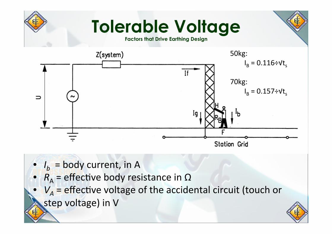
Tolerable Voltage Factors that Drive Earthing Design
• Ib=bodycurrent,inA• RA=effecLvebodyresistanceinΩ• VA=effecLvevoltageoftheaccidentalcircuit(touchorstepvoltage)inV
50kg:IB=0.116÷√ts
70kg:
IB=0.157÷√ts
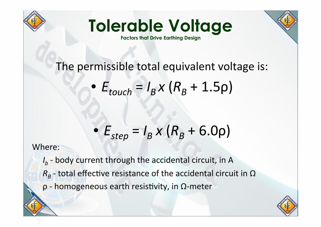
Tolerable Voltage Factors that Drive Earthing Design
Thepermissibletotalequivalentvoltageis:
• Etouch=IBx(RB+1.5ρ)
• Estep=IBx(RB+6.0ρ)Where:
Ib-bodycurrentthroughtheaccidentalcircuit,inARB-totaleffecLveresistanceoftheaccidentalcircuitinΩρ-homogeneousearthresisLvity,inΩ-meter

Surface Material Resistivity Factors that Drive Earthing Design
• AlayerofhighresisLvitymaterial(gravel)isojenspreadabovetheearthgridtoincreasecontactresistancebetweenthesoilandthefeetofpersonsinthesubstaLon
• ThecurrentthroughthebodywillbeloweredconsiderablywiththeaddiLonofthesurfacematerialbecauseofthegreatercontactresistancebetweentheearthandthefeet
• ThereducLondependsontherelaLvevaluesofthesoilandthesurfacematerialresisLviLes,andonthethicknessofthesurfacematerial.
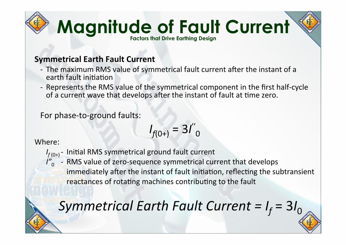
Magnitude of Fault Current Factors that Drive Earthing Design
SymmetricalEarthFaultCurrent- ThemaximumRMSvalueofsymmetricalfaultcurrentajertheinstantofaearthfaultiniLaLon
- RepresentstheRMSvalueofthesymmetricalcomponentinthefirsthalf-cycleofacurrentwavethatdevelopsajertheinstantoffaultatLmezero.
Forphase-to-groundfaults:
If(0+)=3Iʹʹ0Where:
If(0+)- IniLalRMSsymmetricalgroundfaultcurrentI”0 - RMSvalueofzero-sequencesymmetricalcurrentthatdevelops
immediatelyajertheinstantoffaultiniLaLon,reflecLngthesubtransientreactancesofrotaLngmachinescontribuLngtothefault
SymmetricalEarthFaultCurrent=If=3I0

Duration of Fault Current Factors that Drive Earthing Design
TolerableEarthFaultCurrentisinverselyrelatedtothesquarerootofexposure/me:
IBαk÷√ts*Shortexposure/memeanshightolerablevalues*Longexposure/memeanslowtolerablevalues
TheallowedcurrentvaluemustbebasedonCLEARINGTIMEof:
Ø PrimaryprotecLvedevicesØ BackupprotecLvedevices
Primaryprotec7onclearing7meispossibleduetolowcombinedprobabilitythatrelaymalfunc7onswillcoincidewithallotheradversefactorsnecessaryforanaccident
Backupprotec7onclearing7meismoreconserva7vebecauseofgreatersafetymargin
Researchprovidesevidencethatahumanheartbecomesincreasinglysuscep/bletoventricular
fibrilla/onwhenthe/meofexposuretocurrentisapproachingtheheartbeatperiod,butthedangerismuchsmallerifthe/meofexposuretocurrentisintheregionof0.06sto0.3s(3.6cyclesto18cycles)
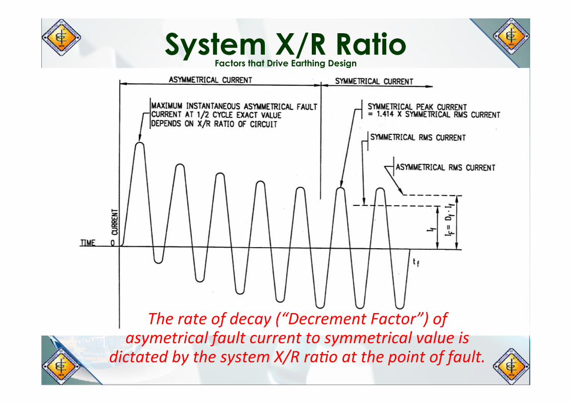
System X/R Ratio Factors that Drive Earthing Design
Therateofdecay(“DecrementFactor”)ofasymetricalfaultcurrenttosymmetricalvalueis
dictatedbythesystemX/Rra/oatthepointoffault.

Earthing Design Guide IEEE 80-2000

Earthing Design Guide IEEE 80-2000
LevelsofDesignEngineeringCalculaLons:Ø TechnicalSpecificaLon(LimiLngValues)
• SystemPerformanceCriteria• EquipmentSelecLonfor:
o RegulatoryandStandardsComplianceo Procurement
Ø ProtecLon,ControlandInstrumentaLon(PCI)Semng• PrimaryPCIsemngs• BackupPCIsemngs• ProtecLonZonesCoordinaLonsemngs
Earthing Design Guide IEEE 80-2000
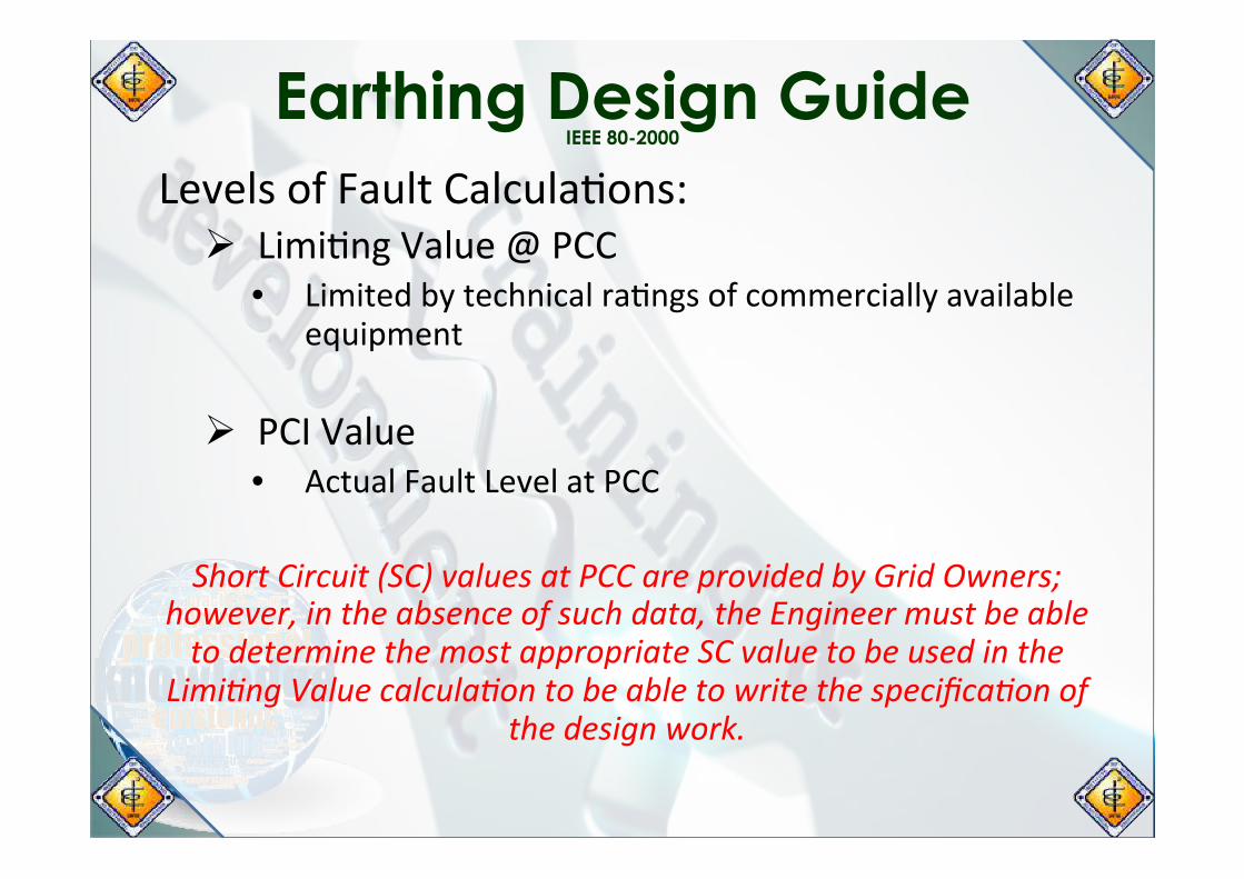
LevelsofFaultCalculaLons:Ø LimiLngValue@PCC
• LimitedbytechnicalraLngsofcommerciallyavailableequipment
Ø PCIValue
• ActualFaultLevelatPCC
ShortCircuit(SC)valuesatPCCareprovidedbyGridOwners;however,intheabsenceofsuchdata,theEngineermustbeabletodeterminethemostappropriateSCvaluetobeusedinthe
Limi/ngValuecalcula/ontobeabletowritethespecifica/onofthedesignwork.

Earthing Design Guide IEEE 80-2000
1. DetermineandselectEarthConductorSize,usingEquaLon37ofIEEE80-2000:
Where:
I - ThreePhaseShortCircuitRMSCurrent,kAAmm2 - MinimumConductorCrossSecLon,mm2
TCAP - ThermalCapacityperUnitVolume,J/cm3.°Ctc - DuraLonofShortCircuitCurrent,secondαr - ThermalCoefficientofResisLvityatReferenceTemp,1/°Cρr - ResisLvityofEarthConductoratReferenceTemp,υΩ-cm1/αº - Ko,°CTm - MaxAllowable(Fusing)Temp,°CTa - AmbientTemp,°CTr - ReferenceTempforMaterialConstant,°C

Earthing Design Guide IEEE 80-2000
2. CalculateEarthGridResistance2.1 DetermineandSetEarthGridArrangement;parameterstobeset
are:nrorr - NoofRowsLg - LengthofRowncorc - No.ofColumnWg - LengthofColumn,meterLc - TotalLengthofEarthConductor,meterLp - LengthofPerimeter,meterConductorSize asdeterminedfromstep1D - CrossSecLonalDiameterofearthconductor,meterNumberofElectrodesEarthingElectrodeLength-normally3metersLR - TotalLengthofEarthingElectrode,meterLT - TotalLengthofBuriedConductors,meter

Earthing Design Guide IEEE 80-2000
2.2 CalculateSurfaceLayerDeraLngFactor,asperEquaLon27ofIEEE80-2000:
Where:
ρ - SoilResisLvity,Ω-mρs - ResisLvityofSurfaceMaterial,Ω-mhs - ThicknessofSurfaceLayer,meterCs - SurfaceLayerDeraLngFactor
2.3 CalculateEarthingGridResistance,asperEquaLon52ofIEEE80-2000:
Where:
h - DepthofConductor,meterA - AreaOccupiedbyConductor,m2
Rg - EarthGridResistance,
𝐶𝑠 = 1−(0.09(1−𝜌/𝜌𝑠)/(2ℎ𝑠+0.09))
𝑅𝑔=𝜌[1/𝐿𝑡+(1/√20𝐴)∗(1+(1/((1+ℎ∗√20/𝐴))]

Earthing Design Guide IEEE 80-2000
3. CalculateMaximumGridCurrent3.1 CalculateMaximumSymmetricalEarthFaultCurrent
Ig=(Iomax)xSfWhere:
Iomax - MaxSymmetricalEarthfaultCurrentSf - CurrentDivisionFactorIg - SymmetricalGridCurrent
3.2 CalculateDCTimeOffset,asperEquaLon74ofIEEE80-2000:Where:
X/R - X/RRaLoatFaultf - FrequencyTA - DCTimeOffset,Ta
Earthing Design Guide IEEE 80-2000
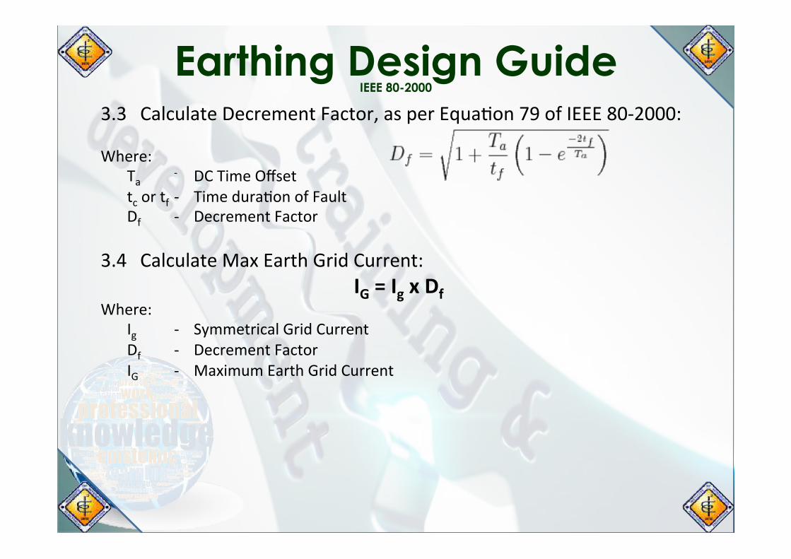
3.3 CalculateDecrementFactor,asperEquaLon79ofIEEE80-2000:Where:
Ta - DCTimeOffsettcortf- TimeduraLonofFaultDf - DecrementFactor
3.4 CalculateMaxEarthGridCurrent:IG=IgxDf
Where:Ig - SymmetricalGridCurrentDf - DecrementFactorIG - MaximumEarthGridCurrent

Earthing Design Guide IEEE 80-2000
4. CalculateVoltageGradientLimits4.1 CalculateMaximumTolerableTouchPotenLal:
For50kg:For70kg:
Where:Cs - SurfaceLayerDeraLngFactorρs - ResisLvityofSurfaceMaterial,Ω-mts - TimeduraLonofFault
4.2 CalculateMaximumStepPotenLal:For50kg:
For70kg:Where:
Cs - SurfaceLayerDeraLngFactorρs - ResisLvityofSurfaceMaterial,Ω-mts - TimeduraLonofFault
Earthing Design Guide IEEE 80-2000
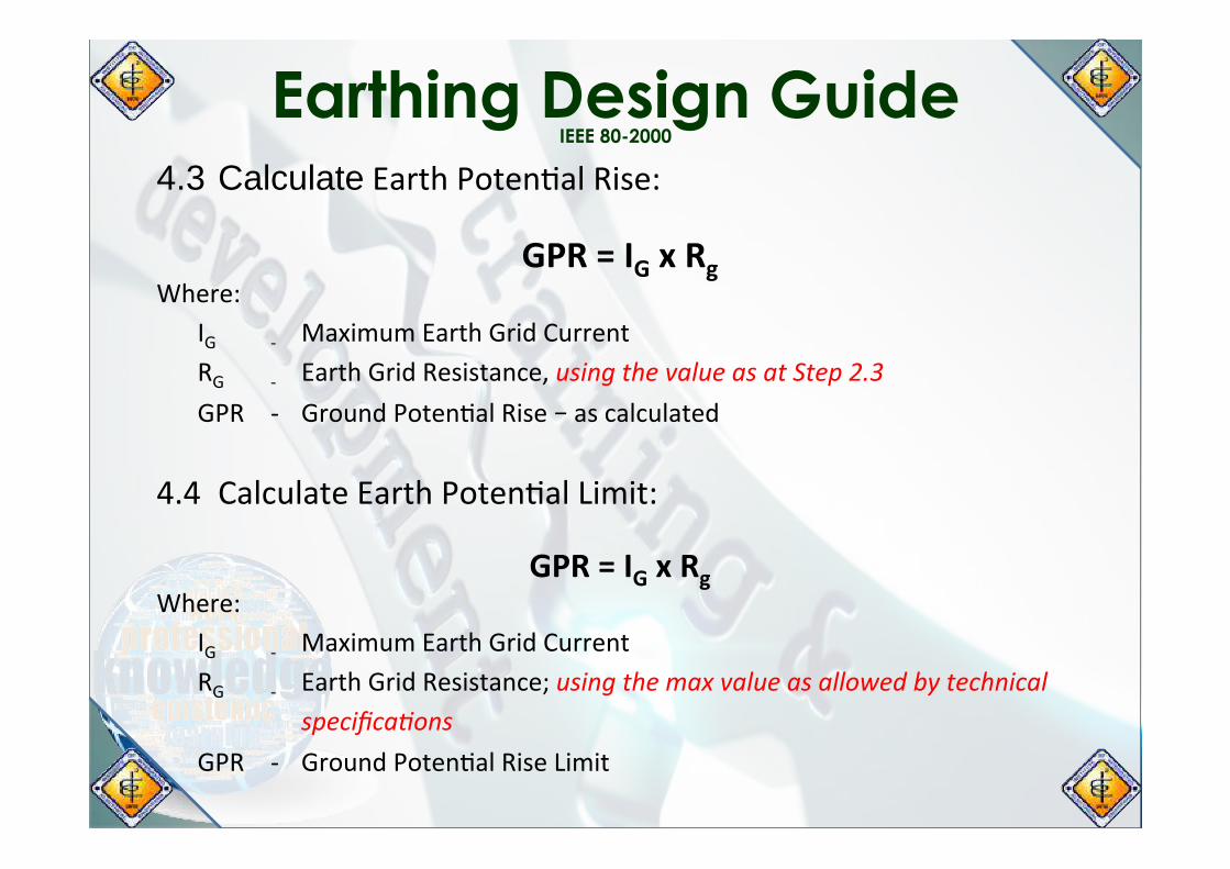
4.3 CalculateEarthPotenLalRise:
GPR=IGxRgWhere:
IG - MaximumEarthGridCurrentRG - EarthGridResistance,usingthevalueasatStep2.3GPR - GroundPotenLalRise–ascalculated
4.4 CalculateEarthPotenLalLimit:
GPR=IGxRgWhere:
IG - MaximumEarthGridCurrentRG - EarthGridResistance;usingthemaxvalueasallowedbytechnical
specifica/onsGPR - GroundPotenLalRiseLimit

Earthing Design Guide IEEE 80-2000
4.5 EarthDesignValidaLonandVerificaLonTouchVoltageCriteria:CalculatedGPR<Etouchlimit;EarthGridDesignisSAFE
StepVoltageCriteria:CalculatedGPR<Esteplimit;EarthGridDesignisSAFE
IftheabovevoltagelimitsofEtouchandEsteparenotmet,the
earthingdesignmustcon7nuetoStep5andbeyond.

Earthing Design Guide IEEE 80-2000
Earthing Design Guide IEEE 80-2000
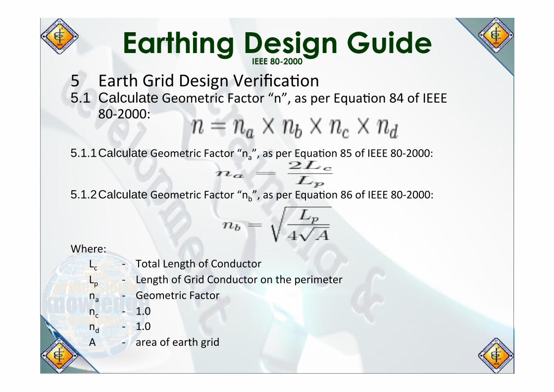
5 EarthGridDesignVerificaLon5.1 CalculateGeometricFactor“n”,asperEquaLon84ofIEEE
80-2000: 5.1.1 CalculateGeometricFactor“na”,asperEquaLon85ofIEEE80-2000:5.1.2 CalculateGeometricFactor“nb”,asperEquaLon86ofIEEE80-2000:Where:
Lc - TotalLengthofConductorLp - LengthofGridConductorontheperimeterna - GeometricFactornc - 1.0nd - 1.0A - areaofearthgrid
Earthing Design Guide IEEE 80-2000
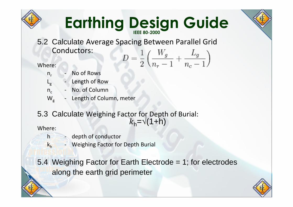
5.2 Calculate AverageSpacingBetweenParallelGridConductors:
Where:
nr - NoofRowsLg - LengthofRownc - No.ofColumnWg - LengthofColumn,meter
5.3 Calculate WeighingFactorforDepthofBurial: Where:
h - depthofconductorkh - WeighingFactorforDepthBurial
5.4 Weighing Factor for Earth Electrode = 1; for electrodes along the earth grid perimeter
𝑘h=√(1+h)

Earthing Design Guide IEEE 80-2000
5.5 Calculate GeometricMeanSpacing,asperEquaLon81ofIEEE80-2000:
Where:
D - SpacingBetweenParallelgridConductors,metersh - DepthofBuriedGridConductors,meterd - CrossSecLonalDiameterofearthgridconductorkh - WeighLngFactorfordepthofConductorkii - WeighLngFactorforElectrodesoncornermeshn - GeometricfactorKm - GeometricMeanSpacing
5.6 Calculate IrregularityFactor,asperEquaLon89ofIEEE80-2000: Where:
n - GeometricfactorKi - IrregularityFactor
Earthing Design Guide IEEE 80-2000
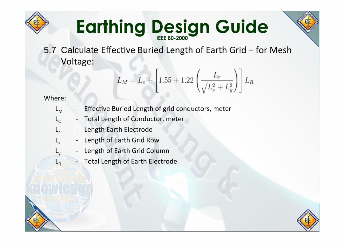
5.7 Calculate EffecLveBuriedLengthofEarthGrid–forMeshVoltage:
Where:
LM - EffecLveBuriedLengthofgridconductors,meterLC - TotalLengthofConductor,meterLr - LengthEarthElectrodeLx - LengthofEarthGridRowLy - LengthofEarthGridColumnLR - TotalLengthofEarthElectrode

Earthing Design Guide IEEE 80-2000
5.8 Calculate MaximumMeshVoltage: Where:
ρs - SoilResisLvityKm - GeometricMeanSpacingKi - IrregularityFactorIG - MaximumEarthGridCurrentLM - EffecLveBuriedLength,formeshvoltageEm - MaximumMeshVoltage
5.9 Calculate Geometric Mean Spacing Factor, as per Equation
94 IEEE 80-2000: Where:
h - DepthofConductorhD - AverageSpacingbetweenParallelGridConductorDn - GeometricFactor,nnKs - GeometricSpacingFactor

Earthing Design Guide IEEE 80-2000
5.10 Calculate EffecLveBuriedLengthofEarthGrid–forStepVoltage:
Where:
Lc - TotalLengthofConductorLR - TotalLengthofEarthingElectrodeLs - EffecLveBuriedLength-ForStepVoltage
5.11 Calculate Step Voltage, as per Equation 92 IEEE 80-2000:
Where:
ρs - SoilResisLvityKS - GeometricSpacingFactorKi - IrregularityFactorIG - MaximumEarthGridCurrentLs - EffecLveBuriedLength,forStepVoltageEs - StepVoltage

Earthing Design Guide IEEE 80-2000

Earthing Design Guide IEEE 80-2000
5.12 Earth Grid Design Validation and Verification: TouchVoltageCriteria:
MeshVoltage(Em)<MaximumTolerableTouchVoltage(Etouch)EarthGridDesignisSAFE
StepVoltageCriteria:
StepVoltage(Es)<MaximumTolerableStepVoltage(Estep)EarthGridDesignisSAFE
IftheabovevoltagelimitsofEtouchandEsteparenotmet,theearthingdesignmustberevisedtoreviewvaluesandassump7onson:
Ø Timedura7onoffaultØ MaximumsymmetricalfaultvalueØ SoilResis7vity;depthofearthconductorØ SurfaceLayerResis7vityandthickness;wetordryassump7onsØ X/RRa7oofsystematPCCØ RequiredearthresistanceØ Areacoveredbyearthgrid

Short Resume
Adelino V. Garcia, Jr. Professional Electrical Engineer – 1584
Chairman and President
AVGarcia Power Systems, Corp. Quezon City, Philippines
www.avgarciapowersystems.com
President
Biyao Hydro Power Corporation
Technical Director Caraga Renewable Energy Corp.
Chairman
Alto Verde Corp.
Chairman Ballesteros Memorial Park
40 Years of Energy Systems Engineering and Integration
Project Management, Execution and Implementation Business Development and Management
Short Resume Adelino V. Garcia Jr. PEE
Expertise and Qualifications: Ø Energy Engineering and Systems Integration of
various technologies such as: Coal Thermal; Combustion Gas Turbine; Heavy/Light Fuel Oil; Biomass and Biogas; Hydroelectric, Solar PV, Wind and Fuel Cell Energy Generation Facilities
Ø Business and Project Development of Conventional and Renewable Energy Generation Technologies

Short Resume Adelino V. Garcia Jr. PEE
Expertise and Qualifications: Ø Project Development, Design and Engineering, Project
Execution and Management, Operation and Maintenance of various Power Generation Facilities (PGFs) Technologies:
Ø More than 3,000MW of Coal: Thermal and Gasification Ø More than 1,500MW of HFO/LFO Diesel: Low; Medium; High Speed Ø More than1200MW Combustion Turbine: Simple and Combined
Cycle Ø More than 100MW of Biomass/Biogas: Thermal; Pyrolysis;
Anaerobic Ø More than 100MW of Hydroelectric: Run-of-River; Pump Storage Ø More than 100MW of Solar: PV and Concentrating Ø More than 50MW of Fuel Cell (Hydrogen Technology): Molten
Carbonate Ø More than 100MW of Kinetic Power: CAES + Buoyancy

Short Resume Adelino V. Garcia Jr. PEE
Expertise and Qualifications: Ø Engineering and Execution of Grid Connection
Facilities for PGFs: Ø 2000MW of 500kV Switchyards Ø 1,500MW of 230kV Switchyards Ø 1,000MW of 115/138kV Switchyards Ø 1,000MW of 72kV Switchyards & Substations Ø 100MW of 36kV Switchyards & Substations
Ø 100MW of 15kV Switchyards & Substations

Q&A
PTDC Committee 2017 Mid Year Convention, Bacolod City 20May2017
Adel Garcia, Jr. – PEE Mobile: +63 917 522 2225 Email - [email protected]


![CLrono'ogy 01 Chinese anc] Islamic Dynasties](https://static.fdocuments.in/doc/165x107/58904aba1a28abbc288c2dc7/clronoogy-01-chinese-anc-islamic-dynasties.jpg)