I—I oo CASE FILE
16
N 7 3- 16091 NASA TECHNICAL NASA TM X-68188 MEMORAN DUM oo oo I—I oo < GO < CASE FILE A METHOD FOR DEFINING DOWN-WIND EVACUATION AREAS FOR TRANSPORTATION ACCIDENTS INVOLVING TOXIC PROPELLANT SPILLS by R. D. Siewert Aerospace Safety Research and Data Institute Lewis Research Center Cleveland, Ohio TECHNICAL PAPER presented at 1972 Joint Army Navy NASA Air Force (JANNAF) Propulsion Meeting New Orleans, Louisiana, November 27-29, 1972
Transcript of I—I oo CASE FILE
N 7 3- 1 6 0 9 1
NASA T E C H N I C A L NASA TM X-68188M E M O R A N DUM
ooooI—Ioo
<GO<
CASE FILE
A METHOD FOR DEFINING DOWN-WIND EVACUATION AREAS
FOR TRANSPORTATION ACCIDENTS INVOLVING
TOXIC PROPELLANT SPILLS
by R. D. SiewertAerospace Safety Research and Data InstituteLewis Research CenterCleveland, Ohio
TECHNICAL PAPER presented at1972 Joint Army Navy NASA Air Force(JANNAF) Propulsion MeetingNew Orleans, Louisiana, November 27-29, 1972

A METHOD FOR DEFINING DOWN-WIND EVACUATION AREAS
FOR TRANSPORTATION ACCIDENTS INVOLVING
TOXIC PROPELLANT SPILLS
by R. D0 Siewert
Aerospace Safety Research and Data InstituteLewis Research Center
National Aeronautics and Space AdministrationCleveland, Ohio
' SUMMARY
Evacuation areas for accidental spills of toxic propellants along therail and highway shipping routes are defined to help local authorities reducerisks to people from excessive vapor concentrations. These criteria alongwith other emergency information are shown in Propellant Spill Cards beingprepared by the Joint Army Navy NASA, Air Force (JANNAF) Safety andEnvironmental Protection Working Group. The evacuation areas are basedon current best estimates of propellant evaporation rates from variousareas of spill puddles. These rates are used together with a continuouspoint-source, bi-normal model of plume dispersion. The rate at which thetoxic plume disperses is based on a neutral atmospheric condition. Thiscondition, which results in slow plume dispersion, represents the widestrange of weather parameters which could occur during the day and night-time periods. Evacuation areas are defined by the ground level boundariesof the plume within which the concentrations exceed the toxic ThresholdLimit Value (TLV) or in some cases the Emergency Exposure Limit (EEL),A margin of safety was used to estimate propellant evaporation rates sinceresearch-data for spills on various surfaces is very limited.

INTRODUCTION
Transportation accidents involving the spill of toxic or volatile chemi-cals pose a threat to the health and safety of populations adjacent to rail orhighway shipping routes. The frequency of these types of accidents will in-crease as more ton-miles for hazardous chemicals are logged each year.The initial reaction to these types of accidents within the first severalminutes by local emergency services probably has the greatest effect uponreducing hazards from fire, explosion and airborne toxic vapors. Accord-ingly, the Joint Army-Navy-NASA-AIR FORCE (JANNAF) Safety and En-vironmental Protection Working Group has prepared emergency proceduresin the form of Propellant Spill Cards for use by shippers and local fire/police departments.
These spill cards include several item of procedure and information,some of it quite similar to material developed by others concerned withsuch types of accidents. However, prior efforts did not deal in any quanti-tative fashion, with an important question: "What size area in the vicinityof a toxic chemical spill should be evacuated to protect people from exces-sive concentrations of airborne vapors?" This report describes the ap-proach used to answer that question.
Evacuation areas are defined by making use of evaporation rate datafor spilled propellants (refs. 1 and 2), their toxicity limits (ref., 3), andan atmospheric diffusion model. This model incorporates standard de-viations of Gaussian distributions of plume concentrations in the cross windand vertical directions (ref. 4). These deviations, based on field experi-ments are related to the more commonly observed weather parameters de-scribing conditions of atmospheric turbulence which affect the rate of toxicplume dispersion. In transportation accidents where a propellant spill islikely to occur or is in progress, there would not ordinarily be anyoneavailable to interpret these weather parameters which affect plume disper-sion rate and the size of evacuation areas. Consequently, an assumed set
of weather parameters was used which will,it is thought, cover a very widerange of situations which conservatively define evacuation areas requiredfor propellant spill evaporation rates„ These evaporation rates have beenreferenced to various areas of spill puddles. Thus the only observationsthat emergency forces need make in selecting an evacuation area are thetype of propellant and the estimated area of its spill puddle.
It should be emphasized that the lead time required to establish anevacuation area may not always be reasonable, especially if the propellantis extremely toxic and has a high evaporation rate. Thus the applicationof criteria described here will not always eliminate, entirely, risks topeople adjacent to toxic propellant spills. Nevertheless, use of these areasshould certainly reduce the number of people exposed to danger and should,moreover, help the emergency forces to avoid ether over- or under-reactingto the threat of airborne toxic vapors.
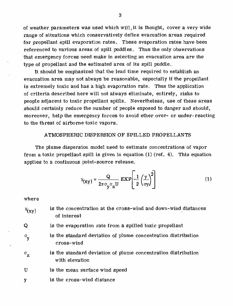
ATMOSPHERIC DISPERSION OF SPILLED PROPELLANTS
The plume dispersion model used to estimate concentrations of vaporfrom a toxic propellant spill is given in equation (1) (ref „ 4). This equationapplies to a continuous point-source release.
-I /y_V2 Voy/
. ... ,2EXP
" \oy-
where
is the concentration at the cross-wind and down-wind distances*(xy)of interest
Q is the evaporation rate from a spilled toxic propellant
a is the standard deviation of plume concentration distribution•7
cross-wind
a is the standard deviation of plume concentration distributionzwith elevation
U is the mean surface wind speed
y is the cross-wind distance
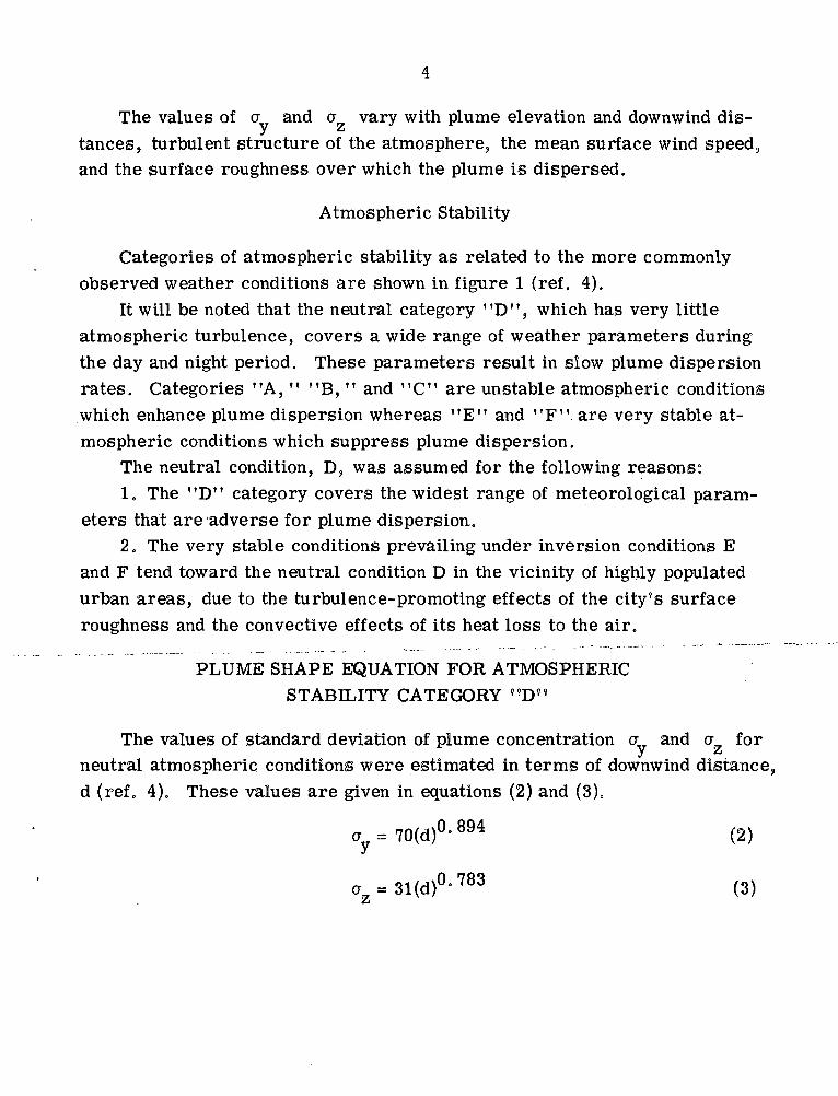
The values of a and a vary with plume elevation and downwind dis-tances, turbulent structure of the atmosphere, the mean surface wind speed,and the surface roughness over which the plume is dispersed.
Atmospheric Stability
Categories of atmospheric stability as related to the more commonlyobserved weather conditions are shown in figure 1 (ref. 4).
It will be noted that the neutral category "D", which has very littleatmospheric turbulence, covers a wide range of weather parameters duringthe day and night period. These parameters result in slow plume dispersionrates. Categories "A, " "B, " and "C" are unstable atmospheric conditionswhich enhance plume dispersion whereas "E" and "F". are very stable at-mospheric conditions which suppress plume dispersion.
The neutral condition, D, was assumed for the following reasons:1, The "D" category covers the widest range of meteorological param-
eters that are adverse for plume dispersion.2. The very stable conditions prevailing under inversion conditions E
and F tend toward the neutral condition D in the vicinity of highly populatedurban areas, due to the turbulence-promoting effects of the city's surfaceroughness and the convective effects of its heat loss to the air.
PLUME SHAPE EQUATION FOR ATMOSPHERICSTABILITY CATEGORY "D"
The values of standard deviation of plume concentration a and a forneutral atmospheric conditions were estimated in terms of downwind distance,d (ref, 4). These values are given in equations (2) and (3).
ay = 70<d)0- 894 (2)
a =31(d)°-783 (3)z

where:
a is the standard deviation of plume concentration distribution,cross wind (m)
a is the standard deviation of plume concentration distribution withzelevation (m)
d is downwind distance (km)
Selecting a mean surface wind speed of 5 m/sec from figure 1 and sub-stituting the values of a and a and U into equation (1), downwind dis-tances can be expressed in terms of propellant evaporation rate "Q" andplume concentrations x as given in equation (4),
/Q\°°6
d = 00001916(-^] (4)VW
where
Q is the propellant evaporation rate (g/sec)o
Y is the plume concentration on the center line of the plume (g/m )
Cross-wind distances of the plume, +y are given in equation (5).
+y = 99. 12(d)°' 894(ln - In X) (5)
where
+y is cross-wind distance (m)
Y is the plume concentration at a distance "y" off the center line ofthe plume

ESTIMATED PROPELLANT EVAPORATION RATES
Data on evaporation rate, Q, for an average wind speed of 5 m/sec
associated with neutral stability condition "D" have been measured for
UDMH/N2H4, N2O4 and LOX (ref. 1) and for anhydrous ammonia (ref. 2).
It has been found that these data, representing highest evaporation rates, plotalmost linearly against the normal boiling points of the four propellants. Thisis shown in figure 2, where the data has been referenced to a spill puddle area
2 2of 55 m (600 ft )„ The remaining propellants are keyed by their normalboiling points to the line established by the data from reference 1 and con-firmed by that of reference 2.
Inspection of figure 2 shows that the propellants fall into five distinct
groups. In view of the fact that errors in estimating evaporation rates signifi-cantly affect downwind concentrations (eq. 4), and that the correlation of fig-ure 2 is based on a limited amount of data a cautious approach seemed to be
required. Consequently, it was decided to assign the highest evaporation rate
for each group of propellants to all members of the group. For instance,nitrogen tetroxide ethylene oxide and chlorine trifluoride were all assumedto evaporate at the rate predicted for chlorine pentafluoride (Group II, fig, 2).
These group evaporation rates are summarized in table L
EVACUATION AREAS
Propellant Toxicity Limits
The final parameter needed to define the boundary of a dangerous plumeby means of equations (4) and (5) is the maximum allowable concentration, \}
of the toxic vapor from the spilled propellant. Here again, as in the casewith evaporation rates, information is not as complete as would be desirable.The criterion that should be applied is the maximum safe concentration whichcan be tolerated by the general public for time durations which would makeevacuation of an area a fesible procedure. Unfortunately, such a criterionhas yet to be established for chemical propellant vapors. Thus it is neces-sary to fall back on other toxicity level standards. One of these standards is
a peak concentration limit set by the American Industrial Hygene Association(AIHA) for workers customarily exposed during their normal work routine.This standard is called, "Theshold limit Value" (TLV). The other standardis an upper limit dosage of short time duration for a once-in-a lifetime ex-posure. This standard is intended for personnel who must be exposed to ac-complish highly essential tasks in emergency situations. This standard wasestablished for chemical propellants by the National Academy of Sciences forchemical propellants and it is called, "Emergency Exposure Limit" (EEL).
Admittedly, industrial workers, exposed to a toxic environment, aremedically examined periodically to assure health requirements for their job.Consequently, they are better able to withstand toxic fumes which may evenslightly exceed the TLV when compared to the general public with its infantsand aged, infirm, or ill people. Offsetting is the fact that a transportationaccident involving a toxic spill will be a rare event within a lifetime andmorever, the exposure will be of limited duration particularly if areas areevacuated as recommended in this report. Therefore, substitution of theTLV's (ref. 3) for v and v (eqs. 4 and 5) should define the ground levelplume boundaries in a conservative manner.
This procedure was followed for all but three propellants. Fluorine,oxygen difluoride and diborane have such low TLV'S and high evaporationrates that their use in equations (4) and (5) defines extremely large toxicplumes extending many kilometers downwind from the spill. The smalllead time available in event of large spill of these propellants would makeevacuation of such an area unrealistic. In fact, these situations may call forimmediate rescue and first aid followed by medical attention. Thus, the ten-minute EEL'S (ref, 3) were used instead of the TLV's to arrive at morerealistic boundaries of the evacuation and/or rescue areas. Counteracting,this seemingly unconservative approach is the extreme reactivity of all threematerials. This makes it very likely that spills will result in fire, the com-bustion products of which are less toxic than the propellants themselves.Other compensating factors are that the fire often induces sufficient atmos-pheric turbulence to dilute the plume concentrations and that both fluorine

8
and diborane react with water vapor in the air, again with the formation ofless toxic products.
Determination of Evacuation Areas
The evacuation area for a given propellant was constructed as shown infigure 3 by first defining the ground level boundaries of the cigar shapedplume consistant with the TLV (or the EEL),, The plume area was then ro-tated +15° off the center line of wind direction to account for possible windfluctuations associated with the neutral, D, atmospheric conditions. A linewas then drawn tangent to the largest width of the plume at an azimuth of15° relative to wind direction„ Finally, an exclusion area around the pointof spill was defined by a radius equal to half the largest width of the toxicplume0 Typical evacuation areas are compared in figure 4, In figure 5, oneof the proposed spill cards is represented to show how the information onevacuation areas is presented.
CONCLUDING REMARKS
The motivation for the present work was a desire to provide somethingbetter than the general instruction, often found in safety documents, to cleardownwind areas in the event of a toxic spill„ In the process of defining rea-sonable areas to be evacuated, three sources of uncertainty were encounteredand in each case an attempt was made to deal with the uncertainty in such away as to provide an added margin of safety. The first source of uncertaintyis weather conditions, but this can be dealt with by assuming that conditionswill always be unfavorable for rapid dilution and dispersion. The other twoproblem areas are evaporation rates and toxicities. More work is needed inboth cases to reduce uncertainty in establishing evacuation areas, not only forliquid propellants, but also in the event that the methods presented here areextended to other toxic chemicals shipped in bulk quantities. Evaporationrates should be measured for more chemicals, on various spill surfaces,
and the substances measured should have a wide range of boiling points.Perhaps the most pressing need is to define a level of toxicity for each chemi-cal that can be tolerated by the general public in the typical environment ofa transportation accident.
REFERENCES
!„ Henderson, W. Paul; and Brown, Ralph H0: Evaporation Rate Studiesof Liquid Oxygen and 50/50 Mixture of Unsymmetrieal-Dimethylhydrazineand Hydrazine, Rep, EA-TR-4425, Edgewood Arsenal (AD-874737),Sept, 1970.
2. Matsak, V. G.: Vapor Pressure and Evaporation of Substances in MovableAir. Repo FTD-.TT-63-1044/1+2, Air Force Systems Command(AD-425608), Nov. 8, 1963.
3. Jensen, Andreas V.: Chemical Rocket/Propellant Hazards. Vol. III.Liquid Propellant Handling, Storage, and Transportation. Rep, CPIA-Pub.-194, vol. 3, Johns Hopking Univ. (AD-870259L), May 1970.
40 Turner, D. Bruce: Workbook of Atmospheric Dispersion Estimates.Publ. 999-AP-26, Environmental Science Services Adm., 1968.
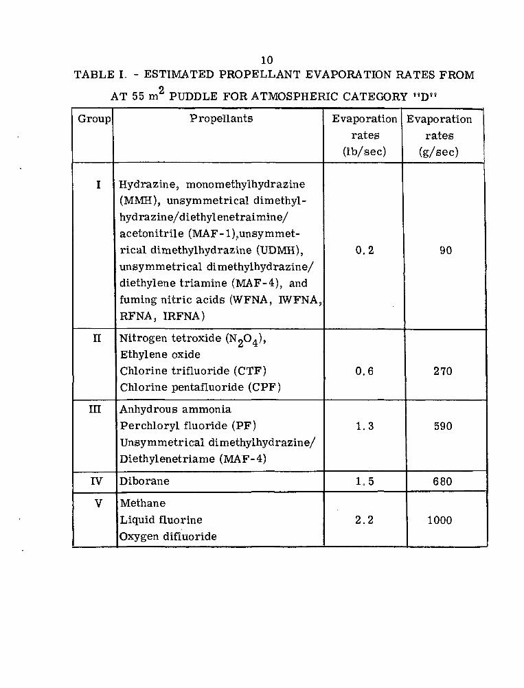
10TABLE I. - ESTIMATED PROPELLANT EVAPORATION RATES FROM
AT 55 nT PUDDLE FOR ATMOSPHERIC CATEGORY "D«
Group
I
n
m
IV
V
Propellants
Hydrazine, monomethylhydrazine(MMH), unsymmetrical dimethyl-hydra z in e/d i ethyl enetrai min e/acetonitrile (MAF-1 ̂ unsymmet-rical dimethylhydrazine (UDMH),unsymmetrical dimethylhydrazine/diethylene triamine (MAF-4), andfuming nitric acids (WFNA, IWFNA,RFNA, IRFNA)
Nitrogen tetroxide (NoO^),Ethylene oxideChlorine trifluoride (CTF)Chlorine pentafluoride (CPF)
Anhydrous ammoniaPerchloryl fluoride (PF)Unsymmetrical dimethylhydrazine/Diethylenetriame (MAF-4)
Diborane
MethaneLiquid fluorineOxygen difluoride
Evaporationrates
(Ib/sec)
0.2
0.6
1.3
1.5
2.2
Evaporationrates
(g/sec)
90
270
590
680
1000

SURFACE WIND(SPEED AT 10 m ELEV),
mSEC'1
<2
2-3
3-5
5-6
>6
KEY TO STABILITY CATEGORIES
DAY
INCOMING SOLAR RADIATION
STRONG
A
A-B
B
C
C
MODERATE
A-B
B
B-C
C-0
1&
SLIGHT
B
C
C
&
0
NIGHT
>4/8 LOW CLOUD
E
0
D
&
<3/8 CLOUD COVER
F
E
E)
&
Figure 1. -Atmospheric stability categories.

GROUP I
400
300
NORMALBOILINGPOINTS, 200
K
100
•UDMH
N204
ANYDROUSAMMONIA
A
HYDRAZINE
MONOMETHYLHYDRAZE (MMH)NITRIC ACIDASYMMETRICAL DIMETHYLHYDRAZINE-
DIETHYLENETRIAMINE (MAF-1)UNSYMMETRICAL DIMETHYLHYDRAZINE (UPMH),
PENTABORANE AND A/1AF-4
GROUPII
NITROGEN TETROXIDE(N204)
ETHYLENE OXIDE AND CHLORINETRIFLUORIDE(CTF)
CHLORINE PENTAFLUORIDE (CPF)
GROUP III
— ANHYDROUS AMMONIA
— PERCHLORYL FLUORIDE (PF)— MAF-3
GROUP IV
DIBORANE
GROUP V
OXYGEN DlFLUORIDE
LIQUIDE METHANE
LIQUID FLUORINE
LOX
I I I _J I200 400 600 800
EVAPORATION RATES, g/SEC1000 1200
Figure 2. - Estimated evaporation rates versus normal boiling pointshazardous for propellants. Wind velocity, 5 m/sec; puddle area,55m2.

l/2y CROSSWIND DISTANCE 7
PLUME
WINDDIRECTION
PLUME
±15° fTOXIC PLUME BOUNDARIES
WIND
Figure 3. - Evacuation area development for toxic propellant spills.

FOR 200 FT' 400^2 600 ^SPILL AREA x V j
AREA TOEVACUATE
FOR 200 FT'SPILL AREA
AREA TO EVACUATE
,400 FT'
600 FT
FOR 200 FT2 400600800SPILL AREA FT -F FT'
ETHYLENE 0X1DE TLV = 90xlO"3 g/m3
NITROGEN TETROX1DE (N204) TLV = 9xlO~3 g/m3
AREA TOEVACUATE
i ' i r
ANHYDROUS AMMONIA
(NH3)TLV=35.0xlO"3g/m3
±15C 1000 YD-
WIND
FOR 200 FT2 400 ^2 600 FTSPILL AREA
AREA TOEVACUATE
FOR 200 FT2 400 FT2
SPILL AREA
600 FT'
SPILL LOCATIONAREA TO
EVACUATE
EVACUATION ROUTE
PERCHLORYL FLUORIDE (PF) TLV = 13.5xlO"3 g/m3 HYDRAZINE (N2H4) TLV = 1.3xlO"3 g/m3
Figure 4. - Propellant spill card evacuation areas for several liquid propellants.

NITROGEN TETROXIDE(OXIDIZER, POISON, CORROSIVE)
POTENTIAL HAZARDS
FIRE
HEALTH
May cause fire on contact with combustibles.Reaction with fuels may be violent.
Vapor may cause severe lung and eye damage.Contact with liquid may cause severe burns toskin and eyes. Contaminated water ormaterial runoff may pollute water supply.
IMMEDIATE ACTION INFORMATIONNO UNNECESSARY PERSONNEL. KEEP UPWIND. IDENTIFYAND ISOLATE HAZARD AREA. WEAR SELF-CONTAINEDBREATHING APPARATUS AND FULL PROTECTIVE CLOTHING.
FIRE
SPILL orLEAK
FIRST AID
Use water spray or fog.Cool containers with water from maximum distance.Use water spray to protect surrounding area.
Evacuate in accordance with the Table of Distances.Stop leak if without risk. Avoid contact with spilledmaterial.Keep spilled material away from combustibles.Use water spray to reduce vapors.Dilute spill with large amounts of water. Dike forlater disposal.
Remove to fresh air. Call physician.If not breathing give artificial respiration.If breathing is difficult give oxygen.Remove contaminated clothing and shoes.In case of contact with material or its water solution, immedi-ately flush skin or eyes with running water for at least 15 minutes.Keep patient at rest.Effects of contact or inhalation may be delayed.
FOR ASSISTANCE CALL 800 424 9300
DO THISNOW
n 1- Get a Helper| | 2. Start Evacua-
tion with circleI I 3. Follow immedi-
ate action infoC3 4. For assistance
call (800) 424-9300 with:
a) your locationand phone no.
b) incident loca-tion
c) label colorand no.
d) name of prod-uct and shipper,if known
e) weather condi-tions'
f) Populated area?g) Water nearby?
CU 5. Advise localauthority tocontrol evacu-ation
D 6. Adjust Evacu-ation Area:
a) According to windchanges
b) According to ob-served effects onpopulation
TABLE OF DISTANCESTO EVACUATE
EVACUATE
Observed Sq. Ft.Area Of The Spill
200 400 600 800
(D)(A)(B)
Circle, Yds.Downwind,Crosswind(Based on
Yds., Yds.TLV)
126528375
126800480
126980600
1261280650
EVACUATIONROUTE
I N I T I A LARl'.A TO EVACUATE
( N O F I R E )
6-12 MPH
IB
1
WATER POLLUTIONCONTROL
Direct runoff of spill to a stream or body of drinking watershould be prevented by diking for later disposal. Evapora-tion of the material to the air at its slow natural rate ispreferable to flooding which will produce large clouds offumes. Nitrogen Tetroxide may kill fish, it reacts withwater to produce toxic products. Residue may be flushedto storm sewers or sanitary system.Advise the EPA or U. S. Coast Guard that a water incidentis in progress.
NOTICE: Although the information compiled herein is believed to be accurate, the JANNAF ad hoc committee on propellant spills accepts no liability for errors in data or the use of the information for any purpose otherthan as a quick-response guide for the best action to be taken during the first 30 minutes following a release of the liquid chemical named. Chemical Propulsion Information Agency, Revision 1, June 1972, avj.
Figure 5.