i/i OF ABL TI VE MATERIALS Ehm EmhEEmhmhohhEE Eh1i ... · 20. ABSTRACT rCon~mae ... S. .Warren M....
84
HD-R133 882 CHARACTERISTICS OF ARIOUS TYPES OF ABL TI VE MATERIALS i/i CPITH ASSOCIATED NAVAL APPLICRTIONS(U) CHARLES STARK DRAPER LAB INC CAMBRIDGE MA J M LEARY MAV 83 UNCLASSIFIED CSDL-T-8il F/G li/7 N Ehm Eh1i EmhEEmhmhohhEE smEEEmhmhhmhh EEEmhEohhhmhEE smhhhEEEEohhE smmhhEEmhEEE-
Transcript of i/i OF ABL TI VE MATERIALS Ehm EmhEEmhmhohhEE Eh1i ... · 20. ABSTRACT rCon~mae ... S. .Warren M....

HD-R133 882 CHARACTERISTICS
OF ARIOUS TYPES OF ABL TI VE MATERIALS
i/i
CPITH ASSOCIATED NAVAL APPLICRTIONS(U) CHARLES STARK
DRAPER LAB INC CAMBRIDGE MA J M LEARY MAV 83
UNCLASSIFIED CSDL-T-8il F/G li/7 N
Ehm Eh1iEmhEEmhmhohhEEsmEEEmhmhhmhhEEEmhEohhhmhEEsmhhhEEEEohhEsmmhhEEmhEEE-

.2*
1111 Igo
1IL25111. . 4 1 .
MICROCOPY RESOLUTION TEST CHARTNATIONAL BUREAU OF STANDARDS- 1963-A
CSDL-T411
CHARACTERISTICS OF VARIOUS TYPES OF ABLATIVEMATERIALS WITH ASSOCIATED NAVAL APPLICATIONS
* by
* James Marcellus Leary
May 1983
Ocen Engineeing/Master of Science ThesisMassachusetts Institute of Technology
DTIC
The Charles Stark Draper Laborator% Inc.CL Cambridge, Massachusetts 02m3
L-Lp
DITRB-rINS ATEtNirf A
Dmiit~~Unlindtc4 0r:S I~Fved oNIP"j

UnclassSECURITY CLASSIICATION OF THIS PAGE (CU.- bags Enited)
REPOR DOCUENTATION PAGE READ INSTRUCTIONS_______________________________________ BEFORECOMPLETINGFORM
1. REPORUNGER 2.GOVY ACCESSION NO. 3. RECIPIENT'S CATALOG NUMBER
14. TITLE r811MSei100le) 43 9; S. TYPE OF REPORT & PERIOD COVERED
Characteristics of Various Types of AblativeMaterials with Associated Naval ApplicationsMatrsTei
S. PERFORMING ORG. REPORT NUMBER
7. AuTmnORC) I. CONTRACT OR GRANT NUMBER(a)
James Marcellus Leary
9 . PERFORMING@ORGANIZATION NAME AND ADDRESS 10. PROGRAM ELEMENT. PROJECT, TASKAREA & WORK UNIT NUMBERS
11. CONTROLLING OFFICE NAMEL A140 ADDRESS 12. REPORT DATECode 031 May 1983Naval Postgraduate School 13. NUMBER OFPAGESMonterey, CA 93943 7
14. MONITORING AGENCV NAME A ADDRESS(if different bran Controlling Office) IS. SECURITY CLASS. (of this report)
16I. DIST01IUUION SIATftNENT (of thte Rolkwotj
App roved for public release; distribution unlimited.
17. DISTRIBUTION STATEMENT (of the abstract entered to, bleck 2.If different boo Report)
IS. SurpLEMENTARY NOTES
19. KEY WORDS (Cmtauau on reverse aid* it nesosay' twl #done#&~ by block numbher)
Evaluating thermal insulation materials for use in thermal protectionof electronic packages exposed to low heat fluxes for short time durations.
20. ABSTRACT rCon~mae.4w revere side of noceoein aid IdenifyU by block number)
DO 1" 1473 EDITI Os, I NOV 451IS OBSOLETE UclsS/N 0102- LIJ.014- 6601 SECURITY CLASSIFICATION or THIS PAGE (Whsen Data lisle'.

CSDL-T-811
CHARACTERISTICS OF VARIOUS TYPES OF ABLATIVEMhTERIALS WITH ASSOCIATED NAVAL APPLICATIONS
by
James Marcellus LearyLieutenant Commander, U.S. Navy
B.S., United States Naval Academy(1974)
Submitted to the Department ofOcean Engineering in
Partial Fulfillment of the Requirementsfor the Degrees of
p.. Ocean Engineer
and
Master of Science inNaval Architecture and Marine Engineering
at the
Massachusetts Institute of Technology
May 1983
@ James Marcellus Leary, 1983
Signature of Author: 1 a eDepartment of Ocean Engineering, May, 1983
Certified By: //A4,A, /1<7,.'& 4 "<- L
S. .Warren M. Rohsenow, Thesis Supervisor
Approved By: ~ ~ 4.'ioga/ Douglas Carmichael, Reader
Accepted By:CChimS.ceR4ngneigDprmn

CHARACTERISTICS OF VARIOUS TYPES OF ABLATIVE
MATERIALS WITH ASSOCIATED NAVAL APPLICATIONS
by
JAMES MARCELLUS LEARY
Submitted to the Department of Ocean Engineering
on May 6, 1983 in partial fulfillment of the
requirements for the degrees of
Ocean Engineer and Master of Science
in Mechanical Engineering
ABSTRACT
This thesis discusses the thermal and mechanical properties ofsubliming, melting, charring, and intumescent ablative materials. Theuse of intumescent ablators as thermal protection in low heat flux en-vironments is emphasized. Models for analysis of transient ablationare discussed. Naval applications of intumescent ablators are examined
Thesis Supervisor: Dr. Warren M. RohsenowTitle Professor of Mechanical Engineering
2
* . .. . . . . .

Accession For
NT-IS GRA&IDTIC TAB U1JraciL1"'flcad El
K ACKNIOWLEDGMENTS
_ _ 1
The author wishes to extend his sincere thanks to Professor Warren
M. Rohsenow, for his support and encouragement during the preparation of
this thesis.
A special measure of gratitude is reserved for Richard Martorana
and the rest of the staff at The Charles Stark Draper Laboratory, Inc.
for their support during this research.
The author is deeply grateful to his wife, Bunny, for her patience
and understanding during the last three years.
Publication of this report does not constitute approval by The
Charles Stark Draper Laboratory, Inc. of the findings or conclusions
contained herein. It is published solely for the exchange and stimu-
lation of ideas.
I hereby assign my copyright of this thesis to The Charles
Stark Draper Laboratory, Inc., Cambridge, Massachusetts.
James Marcellus LearyJ
Permission is hereby granted by The Charles Stark Draper
Laboratory, Inc. to the Massachusetts Institute of Tech-
nology to reproduce any or all of this thesis.
. -3

TABLE OF CONTENTS
Chapter Page
1 INTRODUCTION .............................................. a
2 CHARACTERISTICS OF SUBLIMING AND MELTING ABLATORS ......... 10
S3 CHARACTERISTICS OF CHARRING ABLATORS ...................... 14
S4 CHARACTERISTICS OF INTUMESCENT ABLATORS ................... 22
- 5 MODELING OF TRANSIENT ABLATION ............... 32
: 6 PREDICTING THERMAL PERFORMANCE OF ABLATIVE MATERIALS. ...... 37
I*
7 MECHANICAL PROPERTIES OF ABLATIVE MATERIALS ............... 48
.1
:'!8 USE OF ABLATIVE MATERIALS IN PROTECTING SHIPBOARDSTRUCTURES FROM MISSILE EXHAUST GASES ..................... 52
USE OF INTUMESCENT ABLATIVE MATERIALS AS FIRE-
RETARDANT COATINGS FOR SHIPBOARD APPLICATION .............. 58
10 CONCLUSIONS AND RECOMMENDATIONS ........................... 67
Appendices
A CROSS REFERENCE OF ABLATIVE MATERIAL INDICESTO PRODUCT NAME AND MANUFACTURER .......................... 70
B LIST OF MANUFACTURERS OF IENT ABLATIVEMATERIALS ................................................. 73
LIST OF REFERENCES ............................................... 75
4
9:S FITUECN BATV AEIASA IE
READN OTNSFR HPOR PLCTON........5

LIST OF FIGURES
Figure Page
1 Physical model of a charring ablator ...................... 15
2 Effect of temperature on the thermal conductivityvalue of a charring ablator ............................... 19
3 Effect of temperature on the specific heat valueof a charring ablator ..................................... 19
4 Physical model of an intumescent ablator .................. 23
5 Expansion of intumescent ablative materials ............... 24
6 Effects of temperature on the thermal conductivity valueof an intumescent ablator ................................. 26
7 Effects of temperature on the specific heat value of anintumescent ablator ....................................... 26
5

LIST OF TABLES
Table Page
1 Thermal properties of subliming ablators .................. 13
2 Thermal properties of charring ablators ................... 18
3 Thermal properties of intumescent ablators ................ 28
4 Results of thermal testing ................................ 30
5 Thermal performance parameter for reradiatingsubliming ablators ........................................ 39
6 Initial ranking of the candidate ablative materials ....... 41
7 Results of thermal testing ................................ 42
8 Thermal performance of candidate intumescentablative materials ........................................ 45
9 Ranking of thermal test results and thermal propertyvalues of candidate ablative materials .................... 46
10 Percentage mass loss of candidate ablative
materials during thermal testing .......................... 47
11 Mechanical properties of some ablative materials .......... 49
12 Results of Center for Fire Research thermal tests ......... 63
6
C' .* '.'+.+,: + ;, . ...................................'.:-- >.. , ,.+.........> . ......... i

LIST OF SYMBOLS
Symbol Definition Units
T Fahrenheit temperature
AT Temperature rise OF
k Thermal conductivity value Btu/ft-h-OF~3
P Density value lbm/(ft)
C Specific heat value Btu/lbm-OF
a Thermal diffusivity value (ft) 2/s
H Effective heat of ablation Btu/lbm
q Instantaneous heat flux Btu/(ft) 2- s
Mass loss rate lbm/s
x Penetration depth ft
t Time s
t Time to steady state s
7
C 8;. -

CHAPTER 1
INTRODUCTION
Ablation is a complex energy dissipative process whereby a mate-
rial undergoes combined thermal, chemical, and mechanical degradation
accompanied with a physical change or removal of surface material. The
material transformation can be in the form of sublimation, melting,
char formation, or intumescence. As one researcher, D. L. Schmidt,
wrote, "ablative materials are unique in that they can accommodate vir-
tually any temperature or heat flux condition, automatically control
the surface temperature, greatly restrict any interAal flow of heat, and
are able to expand up to thousands of Btu's of energy for each pound of
material used."
The field of ablation was an area of extensive research during
the preparation for manned space travel and the reusable space shuttle.
As with much research that was done in conjunction with space travel,
ablation theory has been applied to other areas. For instance, ablative
materials have come to be recognized as very effective and practical
fire retardant coatings. The U.$. Navy uses ablative materials as hull
blast protection from the exhaust of ship-launched missiles. In some
applications, ablative materials also contribute to the load-bearing
capability of the substrate by adding structural strength. While these
uses are varied, there are still further areas of application of abla-
tive materials, and in this thesis the application of ablative materials
to shipboard use will be discussed.
8

-,,i .,.. -_ . . .,. . , - -r.w . .- .- J ' . 4C _ ~ _ o .. °o -. -. * *- % ° . -
This thesis is the result of a combined research effort of my-4 self, and two other researchers, Lieutenants Joseph P. Marques, USN,! and Richard A. Schwarting, USN. Our study was concentrated on identi-
fying, analyzing, and evaluating thermal insulation materials to be
used for thermal protection of electronic packages exposed to low heat
fluxes for short time durations. My thesis discusses the thermal and
mechanical characteristics of the major classes of ablative materials.
It also discusses the modeling of transient ablation and the naval ap-
plications of ablative materials. Lieutenant Marques' thesis, titled
"Thermal Evaluation of Ablative Materials in Transient Low Heat Flux
Environments", discusses and reports the results of experimental test-
ing of various ablative materials. Lieutenant Schwarting's thesis was
devoted to developing a couputer simulation model of a particular type
of ablator, and is titled "One Dimensional Model of an Intumescent
Ablator".
9.0

CHAPTER 2
CHARACTERISTICS OF SUBLIMING AND MELTING ABLATORS
Subliming ablators were the orginal ablative material to be
utilized in the U.S. space program. Early space reentry vehicles used
metal heat sink thermal protection systems composed of coppe- or beryllium.
These heat sinks were too heavy, and placed reentry velocity limitations
on the spacecraft. To enlarge the performance envelope of the space-
craft, extensive ablative research was begun. This research effort, which
extended for over twenty-five years, resulted in the development of
the field of ablation. The first ablative material application to
result from this research was the subliming ablator Teflon. Teflon
offered reentry vehicle designers substantial weight savings and good
insulating properties. Teflon and other subliming ablators were used on
the early unmanned space vehicles. The time integrated heat loads
experienced by these subliming heat shields were on the order of 10,000
Btu per square foot. The advent of manned space travel required different
reentry procedures which resulted in the heat shield experiencing a heat
load on the order of 100,000 Btu per square foot. This increased heat
load resulted in excessive subliming ablator thickness, and hence the
decision to use charring ablators.
The reaction process of the subliming ablator is conceptually
simple. The subliming ablator acts as a heat sink to the incident heat
flux until the surface temperature reaches the sublimation temperature.
At the reaction temperature, the virgin material endothermally sublimes,
removing heat from the insulation material. An ablative material such as
10
'v-" -y-,"."-- -..- 4"-'- '., - - -. - - -.. :- _ :-- -:., ;--. -L ., . ,- .. i
Teflon provides very effective insulation due to its low reaction
temperature, and high endothermic value for heat of reaction. The
reaction process of the subliming ablator is easily modeled, and
is often described in heat transfer textbooks.
A melting ablator acts essentially like a subliming ablator, except
that instead of subliming at the reaction temperature, it melts. The
most common type of melting ablators are quartz and nylon. Melting
ablators generally have heat of reaction values similar in value to
subliming ablators, but thermal conductivity values much higher than
the subliming ablators. When compared to other types of ablators, the
melting ablator offers little thermal performance advantage. Ablative
literature lists very few uses for pure melting ablators. However,
melting ablators are added to some charring ablators to improve the
ablative performance of the charring ablator.
The next advance in ablative research was spurred by the
development of the space shuttle orbiter. The shuttle designers needed
a thermal protection system which would survive a minimum of 100
missions (the orginal target was for a 500-mission life). After adecade of extensive research, the decision was made to use a low
erosion reradiating tile. The reentry path of the space shuttle
orbiter results in a low heat flux, long duration pulse. The maximum
heat load is generally modeled as an instantaneous heat flux of
approximately 10 Btu per square foot per second lasting for about
2000 seconds. During this heat flux, the shuttle tiles reach a
service temperature on the order of 2300 degrees Fahrenheit. This
high temperature results in significant reradiation of heat providing
effective insulation to the substrate. Despite this high temperature,
.: the tiles experience very little erosion. The tile thermal protection
system is very lightweight, and allows a large cargo load for the
shuttle orbiter.
:%.
• 11
1g .

The space shuttle orbiter tiles are silica bricks, and are generally
referred to as Reusable External Insulation (REI). The exact class-
ification of these silica bricks is uncertain. Literature classifi-
cations of this material vary from nonablating ceramic to subliming
ablators. Silica itself is sometimes referred to as a melting ablator.
Because the silica tiles sacrifice material in thermally protecting
the orbiter, and the fact that the material is generally sublimed due
to the high temperature, the author feels that the silica bricks
should be classified as a subliming ablator.
The silica bricks are not the only subliming ablator used on
the orbiter. For the surfaces which have significant curvature, such
as the leading edge of the wings, a subliming carbon composite ablator
is used.
The thermal properties of subliming ablators are listed in Table 1.
The evaluation of the thermal parameters of the subliming ablators will
be discussed in Chapter 6. Basically though, due to the relatively high
value of thermal diffusivity, subliming ablators are best suited to
long duration heat fluxes. The space shuttle subliming ablators were
*selected with a design maximun instantaneous heat flux of 50 Btu per
square foot per second. On the fuel tanks and rocket motor which
accompany the orbiter during the space shuttle system launch, this
maximum heat flux is exceeded, and charring ablators are used for
thermal protection.
The major obstacle to the widespread use of subliming ablators is
the form of application. Subliming ablators are usually produced in
tiles. These tiles present bonding problems, vibration resistance
problems, and substrate curvature problems. These problems have been
• .demonstrated in the space shuttle program, by the bonding failure of
tiles during the first few missions. Despite application limitations,
nonspace vehicle uses for subliming ablators are beginning to be
recognized. For instance, the U.S. Navy is interested in using sub-
1,iming ablators as a supplement to an existing ablative blast protection
system.
12

.. 7
Table 1. Thermal properties of subliming ablators.
Material p c k xl106 aLx 106
S-1 9 0.23 4.6 2.22
s-2 15 0.23 4.6 1.33
S-3 15 0.24 11.0 3.06
S-4 8 0.24 9.0 4.69
13

L bE
CHAPTER 3
CHARACTERISTICS OF CHARRING ABLATORS
-p
Charring ablative material was the subject of a great amount of
research prior to manned space travel. When conducting a literature search
on ablation, the great majority of the reports are concerned with charring
ablators. The reason for this interest is the wide range of heat fluxes,
and environments for which charring ablators provide effective thermal
insulation. While intumescent and subliming ablators have somewhat
specialized areas of thermal performance, charring ablators are used in the
remaining spectrum of heat fluxes and thermal environments. Charring
ablators can provide insulation in situations with instantaneous heat
fluxes greater than 100 Btu per square foot per second, and time integrated
heat fluxes on the order of 100,000 Btu per square foot. Charring ablators
also provide excellent insulation in the low heat flux medium pulse dura-
tion environments. Char former (synonym for charring) ablative materials
have been utilized in numerous aerospace applications.
The physical aspects of the charring ablator decomposition process
are illustrated in Figure 1. Initially, the material acts as a heat sink
absorbing all of the incident heat flux. The low thermal diffusivity of
the virgin material entrains the heat in the surface region causing the
temperature of the surface region to rise rapidly. When the material
temperature reaches the reaction temperature, an endothermic chemical
decomposition occurs. Organic components present in the material are
-' pyrolyzed into various low atomic weight gaseous products and residual
acarbonaceous material. These gases percolate through the surface of the
14

FULLY CHARRED REGION
REACTION ZONE
VIRGIN MATERIAL
Figure 1. Physical model of a charring ablator.
material into the boundary layer. The temperature of the residual char
will continue to increase under the influence of the incident heat flux.
Maximum surface temperatures of the surface char can be as high as
2000 degrees Farenheit. If the incident heat flux is greater than 100
-" Btu per square foot per second significant surface recession will occur.
Charring ablators generally produce a char of sufficient mechanical
strength to survive environments of high velocity flows. This strong char
and the release of low atomic weight gases into the boundary layer, result
in the charring ablator achieving a significant insulation mechanism.
% The injection of the decomposition gases increases the thickness of the
% boundary layer, and alters the temperature and velocity gradients. This
gradient alteration results in a reduction of convective heat transfer from
the environment to the ablating material. The pyrolysis gases provide
further insulation by absorbing heat as they pass through the high temp-erature char material on the surface. The combined insulation effect of
the boundary layer thickening, and the heat absorbed by the pyrolyzed
gases is termed transpirational cooling.
The char of the charring ablative material can survive high temp-
eratures which results in reradiation from the insulation material to the
15
lpI

environment. The magnitude of this reradiation is less than the reradia-
tion achieved by subliming ablators, but is still sufficient to help
insulate the substrate.
In sunmary, the substrate is isolated from a major portion of the
incident heat flux through the four mechanisms of the charring ablator.
These four mechanisms are:
(1) The heat capacitance of the virgin and char material.
(2) The latent heat absorbed in the endothermic decomposition
forming the pyrolyzed gases and the char.
(3) The reduced incident heat flux and cooling achieved via
transpirational cooling.
(4) The reduction in the thermal energy of the material due to
the reradiation from the surface of the charred material
to the environment.
The effect of these four mechanisms are combined into a single term
called effective heat of ablation (units of Btu per pound mass). The ef-
fective heat of ablation is generally the parameter of major importance
when discussing charring ablators.
In equation form, the effective heat of ablation is expressed as
H-m
As the equation indicates, the magnitude of the effective heat of abla-
tion is a function of the incident heat flux. The greater the incident heat
flux, or more severe the thermal environment, the higher the value for ef-
fective heat of ablation. Convective heat fluxes also allow greater values for
effective heat of ablation due to the insulating effect of transpirational
16*4
......

cooling. Because the effective heat of ablation is environmentally de-
pendent, it is difficult to predict the actual ablative performance of a
charring ablator without testing.
The high value for effective heat of ablation makes charring ab-
lative material well suited to the severe thermal environment associated
with aerospace applications. The major portion of these heat fluxes are of a
convective nature due to aerodynamic function. The U.S. Navy has also
recognized the value of charring ablators, and is using these materials to
thermally insulate the new shipboard missile launching system.
Some charring ablators have very low values for thermal con-
ductivity and thermal diffusivity. Table 2 lists the thermal properties
of some charring ablators. Chapter 6 of this thesis discusses the value of
these thermal properties of charring ablators. Figure 2 demonstrates
the increase in the thermal conductivity value of a charring ablator as
the material temperature increases. Figure 3 demonstrates the decrease
in the specific heat value of a charring ablator as the material temper-
ature increases. These temperature trends are typical of a charring ab-
lator. Ignoring density effects, the result of these trends is an increase
in the effective thermal diffusivity value as the temperature of the
material increases.
In general, charring ablators are composite-reinforced organic
polymers. The two most common varieties of polymer charring ablators
are elastomers and plastics. To facilitate char formation, the charring
polymer is of the thermosetting type, which means that it has a high degree
of cross linking. The typical charring ablative material designed for high
heat fluxes will be a composite of a char forming resinous matrix and a
melting ablator. Melting ablators such as nylon are used as gas-generating
4 components, and melting ablators such as silica, carbon, or graphite are
used as reinforcing material.
Charring ablators have also been designed for mild heating environ-
ments and fire-retardant systems. The most comnmon family of polymer char-
ring ablators used in these environments is the silicone (siloxane) type.
17
9

Table 2. Thermal properties of charring ablators.
Material p c. k 10 6 L x 10 6 H*
C-1 34.0 0.47 11.9 0.75 --
C-2 62.0 0.38 18.6 0.80 2812
C-3 68.6 0.45 22.2 0.73 --
C-4 40.0 -- 13.9 --
C-5 45.6 20.8
C-6 39.3 17.4 -- --
4 C-7 72.0 0.47 27.8 0.82 5000
C-8 54.0 0.30 23.1 1.43 8000
C-9 102.0 0.28 75.83 2.65 7500
*The effective heat of ablation values are for
= 00 Btu/ft -s at 1 atmosphere pressure
18

... 3
0M
" 0.20
* 0.15
0.10
i I I l I i i i i I i
100 300 500 700 900 1100 1300 1500 1700 1900
TEMPERATURE (*F)
Figure 2. £ffect of temperature on the thermal conductivityvalue of a charring ablator.
0.46-
0.44 -
0.42
w 0.40
mW 0.38
52IL- 0.36
0.34
I I I I I
100 200 300 400 500 600
TEMPERATURE (OF)
Figure 3. Effect of temperature on the specific heat valueof a charring ablator.
19

i
Silicon elastomeric polymers have several advantages over other charring
ablators. These charring ablators have low values for virgin thermal con-
ductivity and thermal diffusivity. They are also lightweight with relatively
good ablative performance. Further, when the silicon material melts it
covers the char preventing further oxidation. The silicon elastomers,
however, experience very rapid surface recession at heating rates in ex-
cess of 100 Btu per square foot per second. Additives including micro-
ballons and reinforcement materials are employed in attempts to improve
the insulative and ablative efficiency of the silicone-based materials.
Silicon rubber in fire-retardant systems provides excellent thermal pro-
tection for the substrate, generates very little smoke, and presents a low
toxicity hazard. Silicone elastomers are generally limited by their low
mechanical strength. The great expense of silicon elastomers is another
limitation to their application use.
Recently, silicon elastoner cork has been the subject of much
attention. The resulting cork composite has one of the lowest values
for thermal conductivity and diffusivity commercially available. With a
density value of only 6 pounds mass per cubic foot, the cork composite is
a very appealing material for use in aerospace or naval vehicle design.
A major drawback to this composite is that it presently has to be applied
in sheets. For surfaces that are irregular with numerous appendages,
the use of sheets presents an application problem. Some literature has
recently been published describing molded cork ablators, but these
descriptions are not specific concerning the range of applications of
molding techniques.
The thermal performance of the cork composite appears to have
limitations. In Lieutenant Marques's testing the cork material experienced
a large temperature rise. Also, tests done by Mr. P.J. Schneider indicate
that a diathermanous condition of cork allows radiative heat fluxes to
pass through the cork causing rapid temperature rises on the surface of the
substrate. Good thermal performance has been reported with cork material
20

in ti.e integrated heat fluxes less than 450 Btu per square foot in magni-
tude. These results are most likely due to the excellent pure insulative
properties, rather than the ablative performance of the cork composite.
The mechanical strength of charring ablators vary as do the thermal
characteristics. There are low-strength materials (silicone) and high-
strength materials (blast protection material). The mechanical strength
characteristics of charring ablators will be discussed more fully in
Chapter 7. But the point to be made is that mechanical considerations
generally do not limit the use of charring ablative material.
2~21
J . *~~****X~*.* . .. . . .

CHAPTER 4
CHARACTERISTICS OF INTUMESCENT ABLATORS
Intumescent materials are the most misunderstood ablative materials.In fact, vendor-provided material advertisements will often fail to
explicitly state that a material is an intumescent ablator. Intumescence
is a heat insulating mechanism where the insulator forms a foam-like
material through enlargement, swelling, or bubbling of the virgin material
under the action of heat. This type of ablative material is best suited
to low heat fluxes and mild thermal environments. Intumescent ablative
materials offer two advantages to the insulation designer. First, as the
intumescent material expands, the thermal conductivity value decreases,
providing excellent insulation for the substrate. Second, the ablative
material forms a dense char which cuts off the oxygen supply to the
substrate. The most common use of intumeseent ablative materials is as
a fire-retardant paint protection for metals, plastics, wood, and other
materials.
The physical aspects of the intumescent reaction is illustrated in
Figure 4. Initially, the material acts as a heat sink absorbing all of
the incident heat. As in charring materials, the low value for thermal
diffusivity causes the heat to be entrained close to the surface of the
material resulting in a rapid rise in the temperature of the surface
region. When the intumescent reaction temperature is reached, a
pyrolysis generation zone forms. The hot pyrolysis gases produced by
the decomposition reactions perculate toward the surface of the ablator.
22

FULLY CHARRED
DECOMPOSITION
Figure 4. Physical model of an intumescent ablator.
23

4%
As the gases come in contact with the virgin material, an expanded region
of lower density foamy material is formed. This region of foamy material
is called the intumesced region. The formation of the intumesced region
causes an increase in the total thickness of the insulation material.
This increase in thickness can be as much as fifty times the thickness
of the original virgin material. Figure 5 shows the intumescent expansion
which occurred during Lieutenant Marques' testing. The incident
surface of the intumescent material will form a char with sufficient heat
input.
50
.4
42.0
40
z
~25.1z
20
0-13.0
z
, 13.6 1.
u 10
'UCL
I-1 I-1(1) 1-2 1-3
CANDIDATE INTUMESCENT MATERIALS
NOTE: I-1 (1) IS MATERIAL I-1 COATED WITH AN ENVIRONMENTALVINYLOID TOPCOAT
Figure 5. Expansion of intumescent ablative materials.
24
ii-

The fact that intumescent ablative material forms a surface char
results in intumescent materials often being categorized as charring
ablators. But the intumescent ablator is much different than the
charring ablator. The most striking difference between the two ablators
is that the intumescent decomposition reaction is exothermic (heat
releasing), while the charring decomposition reaction is endothermic (heat
absorbing). The exothermic reaction could combine with the heat from
the incident heat flux to reduce the substrate insulation protection.
As discussed in Reference 11, the effect of the intumescent exothermic
reaction can be counteracted by the addition of endothermic inorganic
fillers. While the chemical compositions of commercial intumescents is
proprietary, vendors must use endothermic fillers due to the net
endothermic reaction of commercially available intumescent materials.
Mr. P.M. Sawko and Mr. S.R. Riccitiello of NASA Ames Research Center
have done extensive research on the use of the filler material to
improve the thermal performance of intumescent ablative materials.
The second major difference between intumescent and charring ablators
is the response of the thermal conductivity and specific heat values for
the ablative materials to increasing temperature. As shown in Figure 6,
the result of the intumescent reaction is a decrease in the value of
thermal conductivity as the material temperature increases. As shown in
Figure 2 in the previous chapter, the result of the charring reaction is
an increase in the value of thermal conductivity as the material tempera-
ture increases. As shown in Figure 7, the result of the intumescent
reaction is an increase in the value for specific heat as the material
temperature increases. As shown in Figure 3 in the previous chapter,
the result of the charring reaction is a decrease in the value for
specific heat as the material temperature increases. Thus, as the
material temperature increases, the thermal diffusivity value for an
intumescent ablative material decreases, while the thermal diffusivity
value for a charring ablative material increases.
25
. .~ ~ ~ . . .-. . . . . . . . . . . . .- ,-

3.80
k3.60
S3.40
1320-
z~3.00 - 4
2.80
e2.80 A--A -
" I I I I
10 150 200 250 300
TEMPERATURE (*F)
Figure 6. Effects of temperature on the thermal conductivity
value of an intumescent ablator.
0.40 -~.
A
S. 0.38-
0.36-/a 0.30
I-
0.34
0.32
' :I I p
100 150 200 250 300TEMPERATURE (*F)
Figure 7. Effects of temperature on the specific heat valueof an intumescent ablator.
r 26

As mentioned in the previous chapter, charring ablators provide
effective insulation due to their high values for effective heat ofablation. However, effective heat of ablation is generally not
discussed as a parameter of major importance when considering intumes-
cent ablators. Due to the low net endothermic reaction for the intumes-
cent material reaction, intumescent materials would not survive high
heat fluxes or severe thermal environments. The char of the intumescent
material does have poor mechanical strength, and the char is generally
able to remain intact in environments of only low flow velocities.
Thus, intumescent ablators are usually applied to surfaces which will
experience primarily a radiant heat flux. Thus, little transpirational
cooling is achieved with intumescent ablators. The char of the
intumescent ablator will melt at a temperature level of approximately
1000 degrees Fahrenheit, thus, significant reradiation from the
surface will not occur.
The value of intumescent ablators lies in their pure thermal
insulation properties which become most evident and valuable in low
heat fluxes. Thermal properties for various intumescent materials are
listed in Table 3. Intumescent ablators are relatively dense, and have
high values for heat capacitance. The virgin intumescent materials have
low values for thermal diffusivity, and as mentioned before, the value
for thermal diffusivity decreases as material temperature increases. The
expansion ,of the material thickness due to intumescence, increases the heat
penetration depth to the substrate. For insulation used in transient heat
conduction situations, the two most important parameters are a large
4penetration depth and a low value for thermal diffusivity. The intumescent
reaction provides both of these parameters. Transient ablation will be
discussed in more detail in Chapter 5, however, in general, the low heat
regimes in which intumescent ablators are used are situations of transient
heat conduction through the insulation material.
Another value of the use of intumescent ablative materials for use
in low heat flux environments is the relatively low temperature at which
27
! %
-.
-.

~Table 3. Thermal properties of intumescent ablators.
-Material c k x 106 a x 106 H
Vp
I-1 77.8 0.47 37.5 1.03
1-2 75.0 0.20 30.5 2.03
1-3 85.5 0.35 69.4 2.32 2130
1-4 55. 0 0 .46 35.5 1.40
I-5 87.3 0.42 64.0 1.75
'.42
,"
'.4
1-5 8.3 0.2 64. 1.7 p

intumescence begins. As shown by Figure 6, the intumescence reaction
has generally occurred by the time the insulation material temperature
reaches 250 degrees Fahrenheit. For charring ablators, the reaction
temperature is generally in the range of 400 to 500 degrees Fahrenheit.
Thus, while an intumescent ablator has a lower net endothermic heat of
reaction than a charring ablator, the intumescent reaction occurs at a
lower temperature. For low heat fluxes, this lower temperature of
reaction is of insulation value, but for higher heat fluxes, the large
value of the charring heat of reaction outweighs the fact that it
occurs at a higher temperature.
Lieutenant Marques tested the thermal insulation performance of
intumescent and charring ablators during his thesis research. He
exposed the ablative materials to a radiant instantaneous heat flux
of magnitude 10 Btu per square foot per second for periods of 45 to 200
seconds. These tests demonstrated that insulation performance of the
ablative materials is sensitive to total heat load. As shown in
Table 4, during the 45-second heat flux the two best insulators were
both intumescent ablators. However, during the 200-second heat flux,
one intumescent and one charring ablator were the two best insulators.
In practice, intumescent ablative materials are used in applications
where the time integrated heat flux is less than 1000 Btu per square foot.
The results and implications of Lieutenant Marques's testing will be
more fully discussed in Chapter 6.
Intumescent ablative materials possess good mechanical strength
properties. The ablative coating is capable of adding structural strength
to a structure and surviving the blast from a missile rocket. The range
or mechanical properties of the intumescent material, which are discussed
in Chapter 7, give this ablative material a wide range of applications.
One physical parameter that does limit the use of intumescent material is
density. Due to the high density value of this ablative material, there
is a weight penalty associated with its use.
29
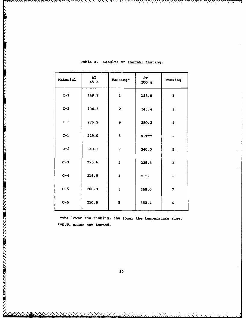
Table 4. Results of thermal testing.
AT ATMaterial 45 s Ranking* 200 s Ranking
I-I 149.7 1 158.8 1
1-2 194.5 2 243.4 3
1-3 276.9 9 280.2 4
C-1 229.0 6N.T**
C-2 240.3 7 340.0 5
C-3 225.6 5 225.6 2
C-4 216.9 4 N.T. -
C-5 208.8 3 369.0 7
C-6 250.9 8 350.4 6
*The lower the ranking, the lower the temperature rise.
**N.T. means not tested.
30
6P,
Most commercial applications of intumescent materials are as a paint
or trowelable coating for fire-retardant purposes. As a paint coating,
intumescent material is used in the fields of civil engineering, aerospace
and aviation vehicles, and naval architecture. Intumescent ablative
materials are being increasingly used in composite insulators. The
intumescent material is applied as a paint over foam material. The
result is a very effective, inexpensive, and lightweight insulator.
Another significant value to the use of intumescent ablative paints is
that they generate only small amounts of toxic combustion gases when
-' exposed to a heat flux.
.
31

CHAPTER 5
MODELING OF TRANSIENT ABLATION
As in most physical processes, ablation processes have both a
transient and steady-state regime. While there is no definitive transi-
tion time, D.L. Schmidt has expressed the time for steady-state ablation
to occur in the following equation
t.,,tss
The transition time for steady-state ablation varies for the dif-
ferent ablative environments. For the high heat flux situation where
charring ablators are used, the transition time can be less than one
second. For the long duration heating situations encountered by the
space shuttle orbiter, the transition time is on the order of 80 seconds.
"4 For fire-retardant situations where intumescent ablative material is
used, the transition time is on the order of 200 seconds.
In modeling the ablation process that will occur in high heat
flux environments, the thermal and chemical reactions that occur during
the transient period are generally assumed to be insignificant in rela-
tion to the reactions that occur during steady-state ablation. This
, same assumption can be made in modeling the ablation process that the
space shuttle orbiter tiles experience. With the transition time for
steady-state ablation being less than 5 percent of the flux duration
experienced by the subliming ablators, the aforementioned assumptions
appear logical. Thus, by considering only the steady-state regime,
32

these ablation processes can be modeled by closed form solutions to
integral equations. These solution techniques are generally similar to
the Goodman Integral Technique. These techniques minimize computer cost
and time consumption in performing studies of the complex problem of the
coupled phenomena of conduction and ablation. Using assumed exponential
profile approximations (which have been refined with experience) surface
recession and in-depth temperature response have been accurately predicted.
In low heat flux environments of short or medium duration, the
transient ablation process can not be ignored. This is the modeling
situation of intumescent and some charring ablators. In Lieutenant
Marques's testing program, the pulse duration of 45 seconds was of major
concern. This pulse duration was well less than the time required to
reach steady-state ablation. Also, ablative materials intended for use
in fire-retardant systems, where the heating duration is on the order of
3 to 5 minutes, require transient analysis.
The transient response of an ablative material is extremely
complex, and the mathematical models to describe this response require
more simplifying assumptions and approximations than in steady-state
ablation to achieve even a numerical solution. For transient ablation,
implicit finite difference techniques are generally employed to solve the
energy equation and the transient heat conduction equation. These so-
phisticated techniques use computer simulation of the governing dif-
ferential equations, and allow designers to vary boundary conditions and
properties of the ablative material. The complete transient solution
will include the decomposition in depth with the attendant density
variations and temperature profiles.
In his thesis, Lieutenant Richard A. Schwarting, USN, modeled
one-dimensional transient ablation of an intumescent material under the
influence of a low heat flux. With an extensive literature search, he
found a very efficient finite difference ablation computer program
.4 written by Donald M. Curry of the Manned Spacecraft Center located in
Houston, Texas. The report detailing this computer program is titled
33

.7
An Analysis of a Charring Ablation Thermal Protection System, while the
computer program itself is titled "Standard Ablation Program (STAB II)".
This analytical model determines the transient one-dimensional ablation
thermal response of a charring ablative material and substrate structure.
The charring ablator is assumed to be composed of three distinct regions
or zones. These zones are:
(1) The charred material zone.._
(2) The zone where the ablation reaction occurs.
(3) The zone consisting of the virgin or unaffected material.
While specifically designed to model a charring ablator, the reaction
zone of the STAB II program can be modeled as an intumescent layer
through the user's input of conductivity and heat of reaction values.
The STAB II program does not accept a "negative" surface recession, or
in other words, the expansion of an intumescent material.
The STAB II program is a sophisticated design tool which permits
a variety of environmental conditions and thermal boundary conditions.
The range of application of the model is increased by its ability to
accept up to twelve separate backup materials with or without air gaps
between the individual materials. Thermophysical properties of the
ablative material may be constant or functions of one or two variables.
When heated, the rate of decomposition of the ablating material is
,* modeled by the Arrhenius kinetic rate expressions. This allows the abla-
* tion process to be sensitive to variations in pressure and temperature.
The surface heat inputs can be in the form of incident heat flux (con-
vective or radiative), or in the form of in-depth temperature time his-tories. The output of the model includes in-depth temperature response
of the ablative material and substrate structure and instantaneous and
time-integrated heat flux information.
Ablation modeling similar to Lieutenant Schwarting's thesis has
been performed at the National Aeronautics and Space Administration Ames
Research Center (NASA Ames). The Chemical Research Projects Office of
NASA Ames has pioneered in the development of intumescent paints, and
34
4%.4
' * ~ **-7. v- . . . . . . . . . ... .-7-7-7
rigid and semirigid foams for application as thermal protection systems.
These researchers have also modified an existing charring ablation simu-
lation program (Aerotherm Charring Material Thermal Response and Abla-
tion Program) to treat both charring and intumescing materials. The
modified program is titled Aerotherm Transient Response of Intrimescing
Materials (TRIM). This program is tailored specifically to a certain
intumescent coating developed by NASA Ames. The authors of the program,
in the article "Analytical Modeling of Intumescent Coating Thermal Pro-
tection System in a JPS Fuel Fire Environment", discuss the sensitivity
of the program to thermophysical data of the ablating material. The
ablation modeling done at NASA Ames was supported by the thermal testing
of Mr. P.M. Sawko and Mr. S.R. Riccitiello.
As highlighted by the NASA Ames work and verified by Lieutenant
Schwarting's work, the accuracy of the finite difference computer solu-
tions is a direct function of the ability of the designer to describe
the temperature and time variations of the thermophysical properties of
the ablating material. This limitation requires that thermal testing
be done in concert with computer modeling to allow the adjustment of the
model to reflect the actual ablation phenomena. Lieutenant Marques's
thesis study was the thermal testing to support Lieutenant Schwarting's
computer modeling.
The work of Lieutenants Schwarting and Marques was a form of a
* technique for determining thermophysical properties called nonlinear
, ~ parameter estimation. With this technique, a researcher first conducts
an experiment measuring the thermal response to a known heat flux. Con-
currently, an accurate computer simulation is developed. Next, a non-
linear parameter estimation computer algorithm is used to determine the
thermal properties of the material. This algorithm derives the thermal
properties of interest that result in the final simulation predicted
thermal response duplicating the actual experiment result. The thermal
properties thus derived are those which must have existed in order forthe measured response to have occurred. While Lieutenant Schwarting's
35
, _ . .. S. - ., -.. . . . . - .. ... .......,. '. - _ ...... S' -. . ,

- -'-- - -. " . -.- - -.."7--;-- 'r u--"--° " "-
.-I
program did not have a nonlinear parameter estimation algorithm, by
manually varying thermal properties, he was able to match Lieutenant
Marques's test data. Lieutenant Schwarting's analysis resulted in the
determination of an "effective" thermal conductivity value for the
ablating material which compensated for the inability of the computermodel to handle the intumescent swell.
The Naval Surface Weapons Center located at Dahlgren, Virginia
has begun a testing program using nonlinear parameter estimation tech-
niques to determine thermal conductivity values of virgin and intumescent
ablative material, the intumescent reaction temperature range, and the
proper coefficients of the Arrhenius expressions. Lieutenant Schwarting's
work indicated that these quantities were of major importance in matching
actual ablation performance. The purpose of the Navy Surface Weapons
Center work was to conduct a parametric study of a generic class of
intumescent ablative materials. The result of this study would be the
identification of the most important thermal characterisitics which con-
tribute to the thermal insulation performance of the ablative material.
The knowledge of these characteristics is hoped to be used to design
new more efficient intumescent ablators.
In this chapter, the modeling of conductive heat transfer has been
primarily concerned with one-dimensional heat flow. Because the work
motivating this thesis was in low heat flux regimes for short time dura-
47 tions, two- or three-dimensional effects were assumed to be insignifi-
cant. The accuracy of this assumption was verified by Lieutenant
Marques's testing. However, in many ablative material applications, such
as reentry heat shields, multidimensional heat transfer and ablation
are of major importance. For these applications, the influence of the
multidimensional heat fluxes on the time-dependent surface and internal
temperature responses must be ascertained.
36
P-,
-. .' .; . : ... .'-;......,..,. - . .. .-.. . ... , " - . . . .

.j
L'
CHAPTER 6
PREDICTING THERMAL PERFORMANCE OF ABLATIVE MATERIALS
More often than not, when selecting an ablative material, design-
ers do not always have clear cut selection criteria. While some thermal
properties of the ablative materials are known, there are generally more
unknown properties than known. For instance, when evaluating an intu-
mescent ablative material, the virgin properties are known, but the prop-
erties of the intumesced and char material are generally unknown. Also,
the parameter effective heat of ablation is environmentally dependent
requiring testing under operating conditions to determine its numerical
value. The purpose of this chapter is to provide some insight for the
evaluation of the thermal properties of ablative materials, with partic-
ular emphasis on intumescent ablators.
There does appear to be a usable selection criterion for theevaluation of subliming ablators for use on the space shuttle orbiter.
As discussed by Mr. P.J. Schneider (Reference 8), in weight-critical
designs with low but prolonged heating, the overal thermal effectiveness
of an ablating material can be evaluated by the following parameter
k
p
The subliming ablators are assumed to achieve the same degree of re-
radiation, therefore relative thermal performance is determined by pure
thermal conduction properties. The above parameter resembles thermal
37
.5.
diffusivity, except that the parameter density is the numerator vice
the denominator of the ratio. The lower the numerical ialue for this
parameter, the more thermal insulation the ablative material will
provide. Table 5 lists various subliming ablators, and the associated
values for this evaluation parameter.
For melting and the other types of subliming ablators, the param-
eter (pkTH) is an index to steady-state thermal performance. AblativeNmaterials with the lowest value of the parameter will have the lowest
ratio of heat flux conducted through the material to heat flux incident
4to the surface of the material. The use of this parameter is lizLited
to the few applications of melting and nonreradiating subliming ablators.
The two aforementioned evaluation parameters are the only two
indices that are discussed in ablation literature. The vast majority
of the evaluation of ablative materials is done via specific thermal
testing. For the space program various charring ablators were tested
under simulated flight environments. While the results of these tests
give designers precise performance information, the cost of this evalua-
tion approach is extremely high.
The purpose of the research that motivated this thesis was to
identify the material which provided the most effective thermal insula-
tion for an electronic package. This package would be exposed to a
radiant heat flux with a time-integrated heat flux equal to or less than
1000 Btu per square foot, and an instantaneous heat flux approximately
*equal to 10 Btu per square foot per second. The current material in
use is an intumescent ablator, but opinions had been offered that
silicon-based charring ablators would thermally perform better than the
present material. For this insulation task, weight was not of primary
concern. This research was considered a preliminary investigation or
survey, which was to be supported with nonsimulation laboratory testing.
To select the candidate materials to be included in the test
program, the various ablative materials were ranked according to the
38
.
9 9.,.- 9 9 9 9 9 9 9 9 9 9 9 .. . . . . . . .

Table 5. Thermal performance parameter forreradiating subliming ablators.
Material Ck a x 10 6
p
S-i 0.0134 2.22
S-2 0.01730 1.33
S-3 0.0263 3.06
S-4 0.01732 4.69
39
Ii,
1 ,% , ' , . ' , . ' . . - • " . - . . . . . . . , , : 7 ' . . . - , . - - . : ' " , 2 , . .2 ' ' ' , - • - "

thermal conduction properties of their virgin material. Based on the
scarcity of ablative literature concerning the low heat flux, short
duration thermal environment, the researchers felt that insulation
properties would be of more importance than ablative properties. Also,
this selection criterion favored silicon-based charring ablative
material. The equation for temperature rise in a semi-infinite body due
to a constant heat flux from the text, Conduction of Heat, was used to
rank the various ablative materials. This equation is
AT = - ierfc
Based on this initial analysis, the research team decided to select nine
materials for evaluation. The selected materials included three intumes-
cent ablators, three silicon charring ablators, one epoxy resin charring
ablator, one silica fiber charring ablator, and one silicon-filled cork
charring ablator. The ranking of these materials based on the above
equation is included as Table 6.
The thermal testing that was conducted is detailed in Lieutenant
Marques's thesis (Reference 16). The materials were exposed to an instan-
taneous radiant heat flux of 10 Btu per square foot per second for dura-
tions of 45 and 200 seconds. The materials were evaluated by the maximum
amount of temperature rise experienced at a selected depth in the material
sample. Table 7 lists the results of these tests.
There are many interesting results from this thermal testing. The
most important result from this work is the verification that the presently
used intumescent material (I-1) provides the most effective thermal
insulation for both the short and long heat flux pulse. Another impor-
tant observation of these test results is that thermal ranking is heat-load dependent. As the pulse duration changed, so did the ranking.
40
' ..

Table 6. Initial ranking of the candidate ablative materials.
Material Ranking*
C-I 1
C-2 2
C-3 3
C-4 4
I-i 5
C-5 6
C-6 7
1-2 8
1-3 9
*The lower the ranking, the lower the
expected temperature rise.
41|a.
a.

Table 7. Results of thermal testing.
Material AT Ranking* AT RankingMaeral 45 s 200 s
I-I 149.7 1 158.8 1
. I-2 194.5 2 243.4 3
1-3 276.9 9 280.2 4
C-1 229.0 6 N.T** i
C-2 240.3 7 340.0 5
C-3 225.6 5 225.6 2
C-4 216.9 4 N.T.
C-5 208.8 3 369.0 7
C-6 250.9 8 350.4 6
*The lower the ranking, the lower the temperature rise.
**N.T. means not tested.
42
9'%
.9 , . 9 9. . 9,," ', 9 ' . " " . '" , '" ." ' ," . ' " ' '' " " "" ., '

While the intumescent material I-1 performed consistently well
on both pulse duration tests, the performance of all the intumescent
materials was not as consistent. The intumescent material 1-2 performed
relatively well on the short duration pulse, but its relative performance
was degraded by the longer pulse duration. Conversely, the intumescent
1-3 performed poorly during the short duration pulse, and its relative
performance improved during the long duration pulse. The performance
trends of the intumescent ablative materials 1-2 and 1-3 match their
applications. The 1-2 material is used primarily in low heat flux fire-
retardant applications. The 1-3 material is used in higher heat flux
environments, such as blast protection from ship-launched missiles.
The intumescent material thermal performance ranked according to
the thermal diffusivity value of the virgin intumescent material. The
lower the thermal diffusivity value, the lower the temperature rise ex-
perienced by the ablative material. Table 8 shows the thermal perform-
ance ranking, and the thermal diffusivity values of the intumescent
materials. The ranking did not change with the change in pulse dura-
tion. These results indicate that possibly the virgin thermal diffusiv-
ity is a reasonable performance measure of intumescent ablative materials.
Only three materials were tested, thus the sample size is too small to
make a significant conclusion. There does appear to be value though, in
conducting a thermal testing program similiar to Lieutenant Marques's to
check the validity of the virgin thermal diffusivity ranking.
While the thermal performance of intumescent ablative materials
ranked according to a quantitative parameter, the thermal performance of
the charring ablators did not. Further, there was no quantitative
measure with which to distinguish between the thermal performance of an
intumescent and charring ablator. Before beginning the testing program,
the researchers had hoped that vendor-provided thermal data could be used
to rank the thermal performance of the ablative materials. Table 9
lists the thermal test ranking, and thermal conductivity, thermal dif-
fusivity, and heat capacitance of the virgin ablative materials. Effective
43
,.0.
S"

heat of ablation values, and reaction temperatures of the materials
could not be used, due to the fact that these pieces of data are not
provided by each vendor. Table 9 demonstrates that there does not
appear to be a parameter with which to predict thermal performance.
This indicates that thermal testing appears to be the only method of
evaluating the suitability of an ablative material for a specific insula-
tion task.
The ablative literature indicates that there will be an eventual
performance crossover between intumescent and charring ablators as the
heat load increases. While there was an improvement in the ranking of
one charring ablator (C-3) during the longer pulse duration, a signif-
icant crossover in performance was not evident. It would be of interest
to continue the testing program at higher heat loads to find the per-
formance crossover point. However, based on this testing, the general
use of intumescent ablative material in applications with heat loads
less than 1000 Btu per square foot appears to be sound.
The author believes the value of intumescent ablative materials
in low heat loads lies in the low effective thermal diffusivity of the
material. As shown by Table 10, intumescent materials experience a
relatively small mass loss during the heat flux exposure. Combining this
small mass loss with the increase in specific heat value of the ablative
material as temperature increases, causes the intumescent material to
have a mugh higher "effective" heat capacitance value than the charring
ablators. Also, the intumescent materials show a decrease in thermal
conductivity values as temperature increases, while a charring ablator
has an increase in thermal conductivity values as temperature increases.
The combined effects of heat capacitance, and thermal conductivity withincreasing temperature causes some intumescent materials to have lower
thermal diffusivity values than charring ablators. This lower "effec-
tive" thermal diffusivity appears to be the reason that the intumescent
material performs well in low heat loads.
44

7 _" - a-
Table 8. Thermal performance of candidate intumescentablative materials.
Material AT AT a x 10645 s 200 s
i-1 149.7 158.8 1.03
1-2 194.5 243.4 2.03
1-3 276.9 280.2 2.32
45
L

.
o..
Table 9. Ranking of thermal test results and themal propertyvalues of candidate ablative materials.
Test Ranking* Thermal properties**
Material
45 s 200 s k x 10 6 ax 106 pc
1-1 1 1 8 4 6
1-2 2 3 7 5 1
1-3 9 4 9 6 4
C-I 6 - 1 2 2
C-2 7 5 4 3 3
C-3 5 2 6 1 5
C-4 4 - 2 - -
C-5 3 7 5 -
C-6 8 6 3
*For test ranking, the lower the ranking, the lower the temperaturerise.
**For thermal properties, the lower the ranking, the lower the numerical
value of the property.
46
9°. e ,- - - -, . . .° ° , ,°- -, . , ° , . . . .

Table 10. Percentage mass loss of candidate ablativematerials during thermal testing.
material Percentage~Mass Loss
I-I 4.2
1-2 2.4
1-3 7.7
:-1 19.7
-2 11.5
3 3.6
0.4
18.9
0.2
7.6
47
-.

,%
5' CHAPTER 7
MECHANICAL PROPERTIES OF ABLATIVE MATERIALS
While most ablative materials are not used as structural members
of the substrate, the mechanical properties of an ablative material
contribute to the range of applications. Some ablative materials are
used isolating the substrate from impinging jet blasts, while other
ablative materials are used in fire-retardant systems with little asso-
*" ciated mechanical stresses. The required mechanical properties of an
ablative material are generally described in a qualitative sense. While
the thermal or heat requirements of an ablative material are generally
precisely delineated in terms of temperature rise of the substrate,
designers can not usually describe accurately the mechanical stresses
that an ablative material will require. The mechanical acceptance of
an ablative material is then usually based on the designer's experience
and testing.
Table 11 lists the mechanical properties of various ablative
materials. This list demonstrates that charring ablators have a wide
range in values of mechanical properties. Charring ablators have been
used as lightweight thermal protection for missiles and as flash pro-
tection for missiles and as flash protection also have a variety of
application techniques.
This research effort was mostly concerned with the mechanical
properties of silicon-based charring ablators. As shown in Table 11,
the silicon-based materials have low values for tensile strength, lap
shear, and hardness. Additionally, there has been mention of a
48
'S.' - ' - " . " ' . . . " - " . "• -'• '•"-• r.o - : ; , m ."- ''-..,"J,"L ' ,' "-

41 -1 z
.844
0J 44 -4 0f Cfloa -4 CIA 0 N1 N 1 01 0 0 0 0 01
4) E4 04 2 0' >
0'4
to
* 4$.4
0
r. E40 0 0CJJ HA IO o on a va o oa o I4 I q ( D 0 1a 1 100 Na (4 v' (4 m' C'4 ON4 ON
-g ) 4
..4
0 00O 0r 0 0 I041
ca 20
41 $.5I-IN M L D - c N 4 N m t
1.49

piezoelectric effect that occurs when silicon-based materials are sub-
jected to a compression-decompression cycle. Some of the silicon- and
nonsilicon-based charring ablators failed to properly bond to aluminum
plates during the preparation for thermal testing. The reader is en-
couraged to read Lieutenant Marques's thesis (Reference 16) for details
on the bonding problem. Other applications of silicon-based charring
ablators use reinforcing filler material of honeycomb metallic structures
to improve mechanical strength. However, these reinforcements substan-
tially degrade the thermal insulation property of the silicon-based
materials.
When compared to silicon-based charring ablators, intumescent
ablative materials have relatively high values for mechanical strength.
The larger mechanical strength values correlate with the intumescent
material having greater density values than the silicon-based charring
ablators. The candidate intumescent materials were easily bonded to
aluminum plates for thermal testing. In some applications, though, bond-
ing problems have occurred with intumescent ablators due to porosity from
entrained solvent or improperly prepared metallic surfaces. Intumescent
materials have a wide range of application methods. These methods include
spraying, troweling, and injection molding. It is interesting that in the
low heat flux regime, intumescent ablative materials not only provide good
thermal capabilities, but also good mechanical properties.
Some values of mechanical properties of subliming ablators are
included in Table 11. These low density materials are chosen to provide
lightweight thermal protection. strength considerations are not the
primary concern with subliming ablators for applications such as the space
shuttle orbiter.
When evaluating the suitability of an ablative material for a par-
ticular application, mechanical testing is generally required. Bondability
is a major acceptance criterion which should be evaluated. Unfortunately,
bondability is extremely sensitive to environment and temperature. There-
fore, the test environment should simulate the actual operating environ-
ment as much as possible. Probably the most informative bondability tests50
.. . . . . . . . . . . . . ..o
° ,- . .< - . - < * -

are the lap shear and peel test. Ease of application and curability of an
ablative material should also be evaluated. Degradation of ablative
material performance has been reported for some application due to water
saturation, oil contamination, ultraviolet radiation, or fungus attack.
Once an ablative material, especially a polymer, is selected, the
mechanical values of hardness, tensile strength, and lap shear strength
become production quality indices. While it is difficult to determine
when the mechanical values become unacceptable, a significant difference
from the normal values acts as a possible indication of loss in produc-
tion quality and control. Using the relatively simple and straightfor-
ward tests for the mechanical properties users can be generally assured
that an ablative material will perform its required function.
-4
.14.
= 51
* . 4

CHAPTER 8
USE OF ABLATIVE MATERIALS IN PROTECTING SHIPBOARD
STRUCTURES FROM MISSILE EXHAUST GASES
The major advancement in naval weaponry since World War II has
been the development and deployment of ship-launched missiles. While the
size and weight of missile systems is roughly equivalent to the size and
weight of naval gun systems, the extremely hot gases flowing at super-
N sonic velocities from ship-launched missiles posed a unique design prob-
lem to naval architects. Ship designers, now, had to contend with the
* problems of thermal expansion causing possible failure of the missile
launching mechanisms, thermal fatigue of heated hull structure, and un-
wanted heat transfer through decks and bulkheads to various spaces in
the ship. Since the early 1960's the Navy has used ablative materials
to achieve the blast and thermal protection necessary to allow missile
systems to be successfully integrated into ship designs.
Before 1975, the Navy used a charring ablator with asbestos fil-
lers as the primary thermal coating for missile launchers and deckC. areas. This coating performed adequately for normal missile launching
exercises, and had a reasonable degree of tolerance to sea and shipboard
environments. Two major deficiencies with this charring ablator became
evident. First, the asbestos filler was a carcinogenic material, and
hence its removal was required by a 1975 Navy policy guideline. Second,
the Navy began to develop sophisticated anti-aircraft weapon systems
which required rapid launching of missiles. This rapid or "ripple"
launch had been shown by fleet exercises to place too great a heat load
on the charring ablator. Missile launchers protected with the charring
52
.1'4 . . . . " - - " * ' + " . . ..
J' . . ' 1 ' . , q . V ' - % ' ' ' ' + . . - ., - ' ' ' " "- . ' ' . " "" " . " . • . • + . . '

ablator were shown to experience too much thermal expansion, and jammed
or failed during rapid launches.
Due to the aforementioned two deficiencies with the charring ab-
lator, the Navy began two replacement research efforts. One research
effort was to find a commercially available ablative material which
could be applied via troweling to existing missile launchers, and could
thermally perform at least as well as the present charring ablator. The
second research effort was much more extensive, and is an on-going pro-
gram. This research effort required testing and modeling of various
ablative materials to determine their thermal response. The object of
this effort was to identify the ablative materials that should be used
in a new missile launching system being developed by the Navy. Both of
the research efforts were performed at the Naval Surface Weapons Center
located at Dahlgren, Virginia.
Mr. John Shea of the Naval Surface Weapons Center was responsible
for the selection of the alternate material for the previously used
charring ablator. His ablative material candidates included both intum-
escent and charring ablators. For the thermal testing, each candidate
material was exposed to a rocket motor exhaust with an associated time
integrated heat flux of less than 1,000 Btu per square foot. This
rocket motor exhaust plume did contain aluminum oxide, an especially
erosive material. For mechanical property evaluation, the candidate
materials were exposed to various severe environments. In addition,
candidate materials were evaluated on: ease of mixing, substrate surface
preparation for bonding, storage life, trowelability, cure time, sur-
vivability to deck traffic, cost, and repairability.
The candidate material which performed well in all areas was an
intumescent ablative material called Flexfram 605. The intumescent
coating was somewhat expensive, but not prohibitive. The selection of
an intumescent coating is not surprising. The heat transfer rate ofless than 1,000 Btu per square foot is in the normal range for intu-
53

mescent ablative material. Mr. Shea stated in his report that as the
heat flux was reduced, the ablative performance advantage of the intu-
mescent material was increased. Also, as discussed in Chapter 7, the
mechanical strength of an intumescent material is generally greater
than charring ablative materials used in low heat flux environments.
There was an added weight penalty due to the higher density of the
intumescent material, but it was felt tha the added weight would not
degrade the performance of the ablative material. As a result of Mr.
Shea's work (references 18 and 27) Flexfram 605 .s become the standard
* ablative coating for use on conventional "above main deck" shipboard
missile launchers.
While the selection of an intumescent coating did solve the as-
bestos contamination problem, and did improve the thermal performance
of the launcher coating system, some serious limitations to missile
operations did still exist. Through testing it was found that using
only trowelable ablative materials, that even an intumescent coating
would survive only one full magazine missile launch. Also, the rapid
missile launch would still cause launcher failure. Due to the design
* and movement of the conventional missile launchers, and the ship hull
* movement in seaways, it was felt that a trowelable material would be
the only material capable of covering all the required areas, and at
the same time have the necessary strength. These limitations indicate
that the conventional launcher, and associated intumescent coating, are
inappropriate for use in a dense anti-aircraft warfare scenario where
rapid missile launches are expected. However, for the scenarios of the
launch of some short-range cruise missiles, antisubmarine missiles, and
self-defense anti-aircraft missiles, the conventional missile launcher
protected with an intumescent coating is indeed appropriate. For the
latter scenario, the limitations of the intumescent coating system re-
sult in virtually no degradation of normal missile operations.
In concert with the heat transfer problems associated with rapid
launches, weapon designers had become aware of the susceptibility of
54
conventional missile launchers to fragment damage. In an anti-aircraft
scenario, a ship might not suffer a direct hit from a missile, but the
fragments from an exploded missile might strike a launcher, rendering;
it nonoperational. This situation became apparent during the Vietnam
War, when a cruiser was struck by only fragments from an exploded mis-
sile. Pierside, the cruiser appeared undamaged; however, the entire
anti-aircraft suite was severely degraded by pierced radars, and pierced
hydraulic and electrical lines to the launcher. To reduce this so
called "cheap kill" possibility, the Navy decided to develop a missile
launching mechanism which would be entirely within the skin of the hull
with no protrusions above the main deck. This launching device is
Ncalled the Vertical Launching System (VLS) due to the vertical launching
orientation of the missiles.
" The heat transfer situation in the VLS is much different than in
,- the conventional missile launcher. The rapid launch requirement, and
the development of a longer range cruise missile increased the heat load
by at least an order of magnitude. The use of intunescent ablative
material was not even considered due to this high heat load. As mention-
ed previously, a second research effort was conducted to test and eval-
uate the thermal performance of various charring, subliming, and melt-
ing ablators for use in the VLS. The results of these tests showed that
subliming ablators of the carbon-carbon composite type experienced the
least erosion when exposed to the test rocket exhaust plume. Both
.4 charring and melting ablative material suffered more erosion. However,
the lower thermal conductivity of the charring ablator resulted in less
heat penetration through the insulation material. The melting ablator
did not offer any performance advantage. The erosion of the charring
ablator, while greater than the erosion of the subliming ablator, was
not unmanageable. The result of this testing was the design of replace-
able charring ablative tiles, which could be replaced by ship's force
personnel when warranted. These ablative tiles consisting of rubber
- modified glass phenolic would be located in the plenum of the launcher
55
* .. . .- .- "- -"- . . .-"..-. - . " - - • -"-- , .

,w~ifl'rw -7 7. -7 .-
where the full rocket motor exhaust would be experienced. The rest of
the missile launcher would be protected with a cast in place charring
ablator.
The ablative system designers for the VLS were able to concen-
trate more on the thermal capabilities than the mechanical capabilities
of the ablative materials. While the ablative materials would be ex-
posed to the rocket exhaust of the missile, these materials would not
be exposed to deck traffic, hull deflections, or the sea environment.
Because the ablative material would not be repaired by ship's force
personnel, trowelability was not a factor in the VLS design.
While it was decided that subliming ablative material was not
best suited to the VLS design, researchers were very impressed by its
performance. At present, research is being conducted to design sub-
*. liming carbon-carbon tiles to be used with the intumescent coatings
on conventional missile launchers. These carbon-carbon tiles would be
small and placed only in the areas of greatest erosion of the intu-
mescent coating. The object for the use of these tiles is to reduce
the amount of coating maintenance required by ship's force personnel.
The result of the charring ablative system design for the VLS
is a weapon system which can very capably handle the heat transfer
load associated with a dense anti-aircraft scenario. Testing has shown
that the VLS is capable of rapid missile launch, and long-range cruise
missile launch. Designers estimate that the VLS can fire seven com-
plete magazines of missiles before refurbishment becomes necessary.
The VLS ablative system is also capable of allowing a complete re-
strained firing (missile does not leave launcher) of a missile. This
restrained firing does necessitate refurbishment of the ablative mate-
rial after the firing of the magazine. However, the missile launcher
and the rest of the magazine is still available to an operational com-
mander after the restrained firing. Because the charring ablative sys-
tem effectively isolates the heat penetration from the rocket exhaust,
56
A A*. . . .

the VLS can be easily integrated into a ship design. The installation
of the VLS on cruisers and destroyers is scheduled to begin in the near
future. The ships that will be outfitted with the VLS will also have
advanced electronics and radars, which will make these ships the most
capable anti-aircraft combatants in the world.
2547
I.,
a.
-°
°4
.. .. . ~..... ..... ...... .. ....... . ;...,. .- ,.--..-,, --

,.1+
CHAPTER 9
USE OF INTUMESCENT ABLATIVE MATERIALS AS FIRERETARDANT COATINGS FOR SHIPBOARD APPLICATION
"Fire at sea is one of the most feared hazards and one of the
greatest dangers confronting shipboard personnel, both in wartime as well
as during peacetime operations. Fire is often the cause of impaired
mission capability, and a major hindrance to continued operation and
combat efficiency in battle. Peacetime fires, whether caused by accident
or arson, pose an equally serious problem. Some of the most tragic fires
have resulted in casualties, considerabe loss in property, costly re-
pairs, and tedious and vexing clean-up operatic s." This quote from the
article "Fire Safe Materials for Navy Ships" written by Dr. D.R. Ver-
triglio succinctly expresses the need for irproved fire protection, andfire-retardant systems for shipboard use.
In the late 1960's, the Navy experienced the two largest shipboard
fires since World War II, neither of which were the result of enemy or
hostile action. In July 1967, the aircraft carrier, the U.S.S. Forrestal
experienced an accidental onboard firing of a five-inch rocket. This
simple pilot error resulted in a catastrophic aircraft carrier flight
deck fire. The end result of this fire was over two hundred million
*dollars of damage, and the loss of life of 134 crew members. When most
present Navy members hear the name of the U.S.S. Forrestal, they are
reminded of the fire-fighting training movie they watched during their
indoctrination training. This movie graphically shows the tragic death
of members of the fire-fighting team as bombs on the flight deck exploded
due to the heat of the fire. Less than two years after the U.S.S. For-
restal fire, another serious aircraft carrier flight deck fire occurred.
58

In January 1969, a rocket warhead onboard the U.S.S. Enterprise allegedly
exploded due to heat impingement of the exhaust from a jet engine starter
unit. The explosion and associated fire resulted in extensive damage to
the ship and onboard aircraft, and serious injury or loss of life of 108
crew members. Safety board findings from both aircraft carrier fires
concurred that shipboard fire-fighting teams simply had insufficient time
to control and extinguish the fires before other munitions ignited and
exploded.
In the past fourteen years, two research efforts involving the use
of intumescent coatings were begun to improve the fire safety of ships.
One research effort was specifically designed to find an ablative coating
which would reduce the danger of self-ignition (cook-off) of ammunition.
The second research effort was an experimental evaluation of the response
of various materials to shipboard fires. Unlike the case of ablative
research for missile launchers, these two research efforts were done by
different groups with no interaction. While the results of the ammuni-
tion self-ignition prevention research have been applied, the results of
the second research effort have not received the attention they deserve.
After the second aircraft carrier fire, the Navy became interested
in finding a coating which could be applied to munitions to decrease the
munitions tendency to self-ignite. At the Naval Weapons Center located
at China Lake, California, different munitions and missile warheads were
exposed to burning JP-5 aviation fuel. These tests were designed to
simulate an aircraft carrier deck fire. Under these experimental condi-
tions, unprotected munitions and warheads exploded within three minutes
of exposure to the fuel fire. With present active fire-fighting equip-
ment and a normal degree of training, a shipboard fire-fighting team
generally requires five minutes to control and extinguish a fire.
After establishing the need for a coating system, the Navy Weapons
Center began testing various coating materials. These tests showed that
an intumescent ablative coating when applied to the warhead of a rocket
increased the average time for self-ignition to at least 8.5 minutes.
.59
|%
.4
• o°S ,.O o .o . . o. . . ... . . •,. .. o...-4..•, ., . , .

The selected intumescent coating for these tests was a commercial product
*manufactured by Pfizer Corporation named Firex. The Firex coating was
.5 applied as a paint with normal spray equipment. Due to the proven fire
retardant capability of the intumescent coating and ease of application,
standards were established for the use of the intumescent paint on se-
lected munitions and rocket warheads. To ensure fire safety, the intu-
mescent coating is also applied to the pipes and valves of the aviation
fuel handling systems, and on selected bulkheads in areas where an avia-
tion fuel fire might occur. Unfortunately, these standards for the use
of intumescent paints apply only to aircraft carriers.
The next tragic shipboard fire occurred in November 1975, when the
aircraft carrier, the U.S.S. Kennedy, and the guided missile cruiser, the
U.S.S. Belknap, collided. This accident depicted at the same time the
merit in the use of intumescent ablative coatings, and the need for fur-
. ther use of passive fire retardant coatings on Navy ships. On board the
U.S.S. Kennedy, the collision ruptured aviation fuel lines causing a
major fire. However, helped by the use of intumescent paint coatings,
the aircraft carrier fire-fighting teams were able to quickly contain the
fire, and with the loss of only one life, extinguish the fire. A short
- time after the collision, the U.S.S. Kennedy was able to continue its
assigned mission with full combat capability. The true heroes in the
containment of the aircraft carrier fire were the qualified fire-fighting
teams, and the excellent fire-fighting equipment. Nevertheless, it
should be pointed out that passive fire retardant intumescent paint al-..
lowed these active fire-fighting procedures to be carried out.
The effect of this collision on the U.S.S. Belknap was much dif-
ferent. Immediately after the collision, a major fire started on the
superstructure of the cruiser. This fire was initially fueled by the
aviation fuel dropped from the aircraft carrier flight deck. The fire
spread quickly through the superstructure, and divided the ship in half
longitudinally with a wall of fire. Fire boundaries could not be set,
60
.......
and therefore, the fire continued to spread rapidly. The heat from the
fire caused some magazine munitions to self-ignite. An officer aboard
the cruiser remarked that the fire spread so quickly that fire-fighting
teams were unable to become organized. This remark is similar to the
findings of the investigations of the 1960's aircraft carrier fires. If
the other ships in the area had not provided quick and effective assis-
tance, the damage to the cruiser would have been more extensive. The
result of the collision and fire on the cruiser was the loss of six lives
and millions of dollars in damage. The U.S.S. Belknap required over
three years to repair.
In 1969, the Navy contracted the Center for Fire Research at the
National Engineering Laboratory, National Bureau of Standards to research
shipboard fire safety. The purpose of this research was twofold:
(1) To improve interpretation and application of present fire
testing methods.
(2) To develop improved laboratory test methods which could
provide meaningful correlation with observed fire buildupin actual fires.
This research project was structured into three phases. The first phase
was a review of shipboard construction materials to determine fire per-
formance. The second phase was the development and performance of labo-*1 ratory fire tests which modeled actual shipboard fires. The third phase
was the interpretation and application of the testing done in the second
phase.
The Center for Fire Research conducted full-size and quarter-scale
shipboard compartment fire tests. The results of these tests provided
valuable insight concerning the behavior of various materials in actual
fires. This research lead to the concept of flashover. Flashover is
defined as the condition when thermal radiation levels become high enough
to simultaneously ignite combustible materials within a compartment. The
concept of flashover was then used to evaluate the performance of passive
61

~~ ~~~ ~~~~~~~~ ~~~~~~ .. .. ,, ., .; * .r. . . . . . . , , , ; . . . i .. . . . . .. . ., .. .. . .
fire retardant coatings. The condition of flashover equates to a bulk-
head temperature of approximately 1200 degrees Fahrenheit, and a radiant
heat flux on the order of 6 Btu per square foot per second.
The Center for Fire Research tests demonstrated the value intumes-
cent ablative paint coatings have as a passive fire retardant coating.As shown by Table 12, in compartments with the hot bulkhead coated with
an intum scent paint, the flashover condition did not occur within ten
minutes. The intumescent paint coating sets effective passive fire bar-
riers which allow shipboard fire-fighting teams the needed time to extin-
guish a fire. The thermal performance of the intumescent paint reported
by the Center for Fire Research appears reasonable based on the testingdone by Lieutenant Marques and E-Systems Inc.
The Center for Fire Research showed another significant advantage
to the use of intumescent ablative coatings. Experimental tests showed
that intumescent coatings greatly reduced the overall generation of car-
bon monoxide, hydrogen cyanide, hydrogen chloride, and smoke in compart-
ment fires. The intumescent paints were shown to be especially suited
for use on submarines. The reduction in both the spread of heat andgeneration of smoke and potentially hazardous combustion gases by intu-
mescent paint coatings allow the normal cooling and filtering systems of
the submarine to maintain a safe atmosphere.
The experimental testing done by the Center for Fire Research
demonstrated that an intumescent coating, to be fully effective, should
be applied to a thickness of at least 0.025 cm. The normal decorative
paint is applied to a thickness of approximately 0.010 cm. Since decora-
tive paint and the intumescent paint have approximately the same density,
there is a weight penalty of about 0.03 pounds per square foot of intu-
mescent application. This appears to be a small weight penalty consider-
ing the fire retardant value of the intumescent coating. However, this
does not mean that every bulkhead in a ship should be coated with intu-
* mescent paint.
62
4
................................. ..................................... .,.. .. . . •::

-4
Table 12. Results of Center for Fire ResearchUthermal tests.
Material Average Bulkhead Average time toTemperature (*F) flashover (min)
Decorative paint 1425 0.5
* Intumescent paint 680 >10
Note: Results based on full scale compartment testingwith the same heat input from a gas burner.
.6
'i' 63
-a. *"*--'.99i~ .

-. 4
Considering the fire tragedies the U.S. Navy has had in recent
years, and the research findings of the Center for Fire Research, one
would expect that the U.S. Navy aggressively utilizes intumescent coat-
ings. However, while the Navy does employ intumescent coatings for iso-
lated applications, there appears to be little interest by ship designers
in fire retardant coatings. The author contacted the design teams of the
current major Navy ship designs, and found very little design effort
(except for submarines) is being applied to make ships less susceptible
to the rapid fire spreading that occurred on the U.S.S. Belknap. The
ship designers, when asked about fire retardant systems, would reply that
the Navy active fire-fighting systems are sufficient to protect ships and
crews. The ship designers base their opinions on preliminary findings of
the British experience during the Falkland Island War. The findings
indicate that if the British had employed U.S. design practices concern-
ing compartment air- and watertight integrity, and active fire-fighting
procedures, the fire damage to their ships would have been significantly
less. The author does not dispute the value of active fire-fighting
procedures, but the author does find that ship designers have not fully
grasped the lessons of the U.S.S. Forrestal, U.S.S. Enterprise, and the
U.S.S. Belknap experiences. Without a time margin to set fire boundaries
and organize fire-fighting efforts, a shipboard fire-fighting team's
effectiveness can be severely limited.
At present, the U.S. Navy has specifications for the application
of intumescent paint on aircraft carriers, submarines, and the new mine
countermeasures ship (MCH). The aircraft carrier application has been
previously discussed, and the following is a discussion of other applica-
tions.
1. To prevent the detonation of magnetic mines, the new MCM ship has
a wooden hull structure. Also to save weight in the design, nonmetallic
materials have been used extensively throughout the ship. The designers
were concerned about the effect a full fire in the engine room of the MCM
would have on the strength of the hull girder system. To prevent hull
64
0'*.1
4. ' ; ' . -. . ,-; - ' " - , _ , ,.. . . , . . . .............. . . . . . "" " "

damage, specifications were made for the use of intumescent paint in the
entire engine room. While this is very effective use of the ablative
fire retardant coating, it does not appear that the intumescent paint is
fully utilized for this design. Considering the ship is heavily con-
structed of composite materials with reduced fire capability, fire re-
tardant coatings should also be used extensively in design. While this
is a weight critical design, the low weight penalty of the intumescent
coating should not degrade the ship design.
The ship type that most effectively uses intumescent fire retar-
dant coatings is the submarine. Polyvinyl chloride nitrile (PVC) rubber
* foam material is used for both thermal and acoustic insulation on the
interior of submarine hulls. However, the Center for Fire Research test-
ing has shown this rubber foam poses a serious fire hazard due to flame
spreading. This danger is accentuated due to the confined space, and
very limited means of securing refuge from fire and combustion products
on board a submarine. The Center for Fire Research conducted specific
tests on the feasibility of coating the PVC foam material with intumes-
cent paint. These tests demonstrated that the ablative coating effec-
tively reduces the fire spread danger of the foam material. Also, the
intumescent paint reduced the amount of harmful combustion products re-
leased to the atmosphere. As a result of the Center for Fire Research
work, intumescent fire retardant coatings are used extensively on U.S.
submarines.
In addition to the U.S. Navy, the offshore platform industry is
interested in using fire retardant intumescent coatings as structure
protection. During the Twentieth Annual Marine Coatings Conference,
laboratory fire tests of structures were presented. These tests demon-
strated that unprotected beams and columns under normal design loads
collapse when the steel temperature reaches 1000 degrees Fahrenheit.
When exposed to a fire, an unprotected column or beam can collapse after
as little as ten minutes of exposure. These tests further showed that
when red hot steel reacts with fire-fighting or other water, very explo-
sive hydrogen gas results. The offshore industry has recognized that
65
J
' - . . * **:. 4 . . . . . -, - - . * . .. . . .

intumescent coatings provide the required fire retardant performance.
Currently, the American Bureau of Shipping and the U.S. Coast Guard are
involved in attempting to set standards for the use of fire retardant
coatings. These coatings will be used to provide protected personnel
escape routes and refuge areas where crews can await rescue. In addi-
tion, coatings will be used to protect essential services such as power
cables, piping, and life support equipment..4
LIM
6..6
"o
-4
esaerue n reug ara heecew a aatrece I di
tion, coatings . will be- -used to prtc essntalsevies uc- pwe

V_ 4.- --
CHAPTER 10
CONCLUSIONS AND RECOMMENDATIONS
The major conclusions and recommendations of this thesis concern
intumescent ablative materials. While few articles are published on
intumescent ablators, the field of application of this material is great.
As a fire-retardant coating, intumescent paints provide a very effec-
tive passive fire barrier which allows time for active fire-fighting
procedures to be carried out. The use of these paints is growing, but
* this growth is limited due to the scarcity of intumescent literature
and advertisement. The weight and cost of intumescent ablative materi-
als are not significant impediments to possible widespread use. As one
thinks about the use of fire-retardant coatings, more applications come
to mind. For instance, Professor Rohsenow, the advisor to this thesis,
observed that intumescent paints would be an excellent way of "fire
proofing" a safe.
The U.S. Navy has a mixed approach to the use of intumescent abla-
tive material. The weapon-system designers use intumescent ablators as
a trowelable missile blast protection for the ship hull. These designers
are conducting extensive research to develop performance standards and
analytical models for the intumescent materials in use. This research
is centered on determining the thermal conductivity and decomposition
behavior of the intumescent material. This work is in the forefront of
intumescent ablative materials research. Unfortunately, this level of
recognition of the value of intumescent materials is not shared bv the
ship designers. While Navy-funded research demonstrated the effective-
ness of intumescent paint as a fire-retardant coating, ship designers
67
4:
do not appear to fully appreciate the utility of this material. Intu-
mescent paints are used effectively on aircraft carriers, submarines, and
mine countermeasure ships; however, these ships account f or less than
30 percent of the U.S. Navy inventory. The lack of published informa-
tion is probably the reason for this lack of application. For instance,
in a recent article in the Naval Engineers Journal titled "Fire Safe
Materials for Navy Ships" (Reference 3), intumescent paint received only
limited attention. Nevertheless, ship designers need to reevaluate
their use of intumescent paints so as to help prevent shipboard fire
tragedies that have occurred in the past.
The work of this thesis research team resulted in some findings
concerning the thermal performance of intumescent ablative materials
and areas for further research. The reader is encouraged to read the
theses of Lieutenants Schwarting and Marques (References 16 and 17) to
fully understand the work of the research group.
The major finding of this research effort was that the baseline
intumescent material (I-1), for the application of concern, provided the
most effective thermal insulation of the candidate materials. The per-
formance ranking of the baseline material did not change with the change
in heat load. Further, Lieutenant Schwarting proved that it was possible
to accurately model the temperature response of this intumescent material.
The mechanical properties of the baseline intumescent material compared
very favorably with the other candidate materials.
An interesting result was observed when the baseline intumescent
material with a vinyloid coating was tested. The specimens with the
coating experienced a larger thickness growth (see Figure 5), and a
smaller temperature rise than the uncoated specimens. The vinyloid
coating which is applied only to prevent handling damage results in im-
proved thermal performance of the intumescent material. This coating
effect should be evaluated further to verify the improved thermal per-
formance. If verified, the coputer model should be adjusted to account
for the coating effect.
68
'".s4fetv hralislto ftecnidt aeil.Tepr
foranc rakig o th baelne ateia di no chnewttecag
~A0 - -in . hea load .Fur ......, ............................... was.ossibl
.- 7-o-7
The research team was unable to develop a performance index with
which to rank the thermal performance of the candidate materials. The
finding that the thermal performance was heat-load dependent was antic-
ipated before beginning the testing program. Thus, it appears that the
only way of determining the relative performance of different types of
ablative materials is through specific testing. Obviously, the more the
test environment approximates the actual environment, the more validity
there will be in the test results.
While the thermal performance of all the candidate materials
could not be ranked according to a distinct parameter, the thermal per-
formance of the intumescent materials could be ranked according to virgin
thermal diffusivity values. Table 8 demonstrates that the lower thermal
diffusivity values of the intumescent material correspond to a lower
material temperature rise. This result was consistent for both pulse
durations. With a sample size of only three materials, it is difficult
to make a definitive conclusion. However, the results do suggest that
there is a possibility of using the thermal diffusivity parameter to
rank intumescent thermal performance. Further testing would be required
to verify this performance index. Appendix B, a list of intumescent
material manufacturers, is provided to aid in further intumescent testing.
The continued thermal testing of the candidate materials at higher
heat loads would be of interest. Ablative literature indicates that at
some level the heat load will be high enough that the charring ablators
will provide more effective insulaLion than intumescent ablators. The
higher heat loads should result in the parameter, effective heat of
ablation, becoming more significant in the insulation process. It would
be interesting to verify the existence and value of the performance
crossover heat load.
69
,""-' . ............................"-. ......- "........................... i... ,_... _ :.

APPENDIX A
CROSS REFERENCE OF ABLATIVE
MATERIAL INDICES TO PRODUCT NAME
AND MANUFACTURER
V..
"V
I7

SUBLIMING ABLATORS
Index Product Name Manufacturer
S-1 LI-900 Lockheed Corp.
S-2 LI-1500 Lockheed Corp.
S-3 Fibrous Silicon Generic
S-4 MOD 1A REI General Electric Co.
CHARRING ABLATORS
Index Product Name Manufacturer
C-I 893-5 Avco Systems Division
C-2 DE-370 Flamemaster Corp.
C-3 DE-350 Flamemaster Corp.
C-4 Fiberfrax LDS Carborundum Corp.
C-5 S-886 Flamemaster Corp.
C-6 S-885 Flamemaster Corp.
C-7 NYLON PHENOLIC Generic
C-8 325 Dow Corning Corp.
C-9 REFRASIL PHENOLIC Hughes Aircraft Co.
71
* 4% . 4
!-*

5'
- 7
INTUMESCENT ABLATORS
Index Product Name Manufacturer
I-i FIREX RX-2373 Pzifer Inc.
1-2 CHARTEK 59 Avco Systems Division
1-3 FLEXFRAM 605 Fiber Materials Inc.
1-4 FIREX RX-2376 Pzifer Inc.
I-5 EX-IC-82 NASA-Ames
1-6 2370 NS Rockwell International Corp.
1-7 477 Ocean Chemical Co.
,72
.4
".
5,
S°
5,i- l e l el

APPENDIX B
LIST OF MANUFACTURERS OF INTUMESCENT ABLATIVE MATERIALS
, Manufacturer Product Name
1. Pzifer, Inc. Firex RX-2370
640 North 13th Street Firex RX-2373
P.O. Box 548 Firex RX-2376
Easton, Pennsylvania 18042
2. AVCO Systems Division Flamarest 1600B
Lowell Industrial Park Chartek 59
Lowell, Massachusetts 01851
3. Fiber Materials, Inc. Flexfram 605
Biddeford Industrial ParkBiddeford, Maine 04005
4. Ocean Chemical Co. 987440 Magazine Avenue 47-135
Savannah, Georgia 31402 478
477
5. Albi Manufacturing 107A
98 East Main Street
Rockville, Connecticut 06066
6. Atomic Weapons Research Mkl
Aldermaston Mk2
Reading, England
73

Manufacturer Product Name
7. Glidden-Durkee Division Insul-Blaze 5027
SCM Corporation
900 Union Commerce Bldg.
Cleveland, Ohio 44115
8. Iowa Paint Manufacturing Co. Fire-Plug 5550
17th and Grand Avenue
Des Moines, Iowa 50309
9. M.A. Bruder and Sons, Inc. Flame-Shield 76-100
52nd and Grays Avenue
Philadelphia, Pennsylvania 19143
10. NASA-Ames Research Center 169
Moffett Field, California 94035 313
EX-IC-82
11. Naval Air Development Center P-124
Warminster, Pennsylvania 18974
12. Naval Surface Weapons Center INSUNOL NX-1871
White Oak
Silver Spring, Maryland 20910
13. Randolph Products Co. 37886
92 North 12th Street
Carlstadt, New Jersey 07072
14. Rockwell International Corp. 2370 AH
Space Division 2370 NS
12214 Lakewood Blvd.
Downey, California 90241
15. VIMASCO Corp. FRP 62-10
Nitro, West Virginia 25143 IA
WC-1
74
-..
REFERENCES
1. Schmidt, D.L., Thermal Parameters of Reentry Ablative Plastics,
Wright Air Development Division Technical Report, WADD TR60-101
1960.
2. Schmidt, D.L., Ablation of Plastics, Directorate of Materials and
Processes Aeronautical Systems Division, Air Force Systems Com-
mand, ASD TR61-650, 1962.
3. Ventriglio, D.R., "Fire Safe Materials for Navy Ships," Naval
Engineers Journal, Vol. 94, No. 5, October 1982.
4. Rohsenow, W.M., and J.P. Hartnett, Handbook of Heat Transfer,
McGraw-Hill Book Co., New York, 1973.
5. Rohsenow, W.M., and H.Y. Choi, Heat, Mass, and Momentum Transfer,
Prentice-Hall Inc., New Jersey, 1961.
6. Bowman, W.H., and R.M. Lawrence, "Ablative Materials for High-
Temperature Thermal Protection of Space Vehicles," Space Re-
sources for Teachers, New York, 1971.
7. Schwinghamer, R.J., "Cork Ablator for Thermal Protection is B-
Staged for Easy Application," Material Engineering, Vol. 93,
No. 4, April 1981.
8. Schneider, P.J., "Correlation of Low Density Thermal Protection
Materials in Mild Heating Environments," AIAA 12th Aerospace
Sciences Meeting, February, 1974.
75

REFERENCES (Cont.)
9. Sawko, P.M., and S.R. Riccitiello, "Improved Intumescent Coating,"
NASA Technical Brief, NTN-78/0178, Spring 1977.
10. Hauser, R.L., "Ablative Coatings," Progress in High Temperature
Coatings, November 1961.
11. Sawko, P.M., and S.R. Riccitiello, Intumescent Ablators as Im-
proved Thermal Protection Materials, NASA Ames Research Center,
Moffett Field, California, 1977.
12. Sauers, D.G., "Water-Based Intumescent Paint," NASA Technical
Brief, Vol. 5, No. 2, Sumer 1979.
13. Laganelhi, A.L., T.P. Harper, and R.P. Fogaroli, "Integral Solu-
tion for Thermal Performance of a Charring Ablator," AIAA/ASME
Thermophysics and Heat Transfer Conference, Boston, Massachusetts,
July 1974.
14. Curry, D.M., Analysis of Charring Ablation Thermal Protection
Systems, NASA TND-3150, 1965.
15. Clark, K.J., A.B. Shimizo, K.E. Suchsland, and C.B. Moyer,
Analytical Modeling of Intumescent Coating Thermal Protection
System in a JPS Fuel Fire Environment, Aerotherm Corporation,
Mountain View, California, 1974.
16. Marques, J.P., Thermal Evaluation of Ablative Materials in Tran-
sient Low Heat Flux Environments, Ocean Engineering Thesis, Massa-
chusetts Institute of Technology, 1983.
17. Schwarting, R.A., One-Dimensional Model of an Intumescent Ablator,
Ocean Engineering Thesis, Massachusetts Institute of Technology,
1983.
76

REFERENCES (Cont.)
18. Shea, J.W. Flexfram 605 ard Dynatherm E-340N Ablatives On Board
USS Kidd (DDG-993) NK 94 BTV Flyaway Firing Results, Naval Sur-
face Weapons Center, NSWC TR81-498, 1982.
19. Sharpe, R.A., Development of Thermal Protective Systems for Air-
craft Applications, E-Systems Inc., Dallas, Texas, 1978.
20. DiGiorgio, J.D., Lockheed Corporation Interdepartment Communica-
tion, March 1982.
21. Carslaw, H.S., and J.C. Jaegar, Conduction of Heat, Oxford Press,
Oxford, 1959.
22. Froberg, R.W., "Thermal Coating Slows Fire Progress," Modern
Paint and Coatings," November 1980.
23. Schmidt, D.L., Interdisciplinary Research on Ablative Materials,
Air Force Materials Laboratory Air Force Systems Command, 1965.
24. Lee, B.T., and W.J. Packer, Fire Buildup in Shipboard Compart-
ments- Characterization of Some Vulnerable Spaces and the Status
of Perdiction Analysis, Center for Fire Research National Engi-
neering Laboratory National Bureau of Standards, May 1979.
25. Lee, B.T., and J.N. Breese, Submarine Compartment Fire Study -
Fire Performance Evaluation of Hull Insulation, Center for Fire
Research National Engineering Laboratory National Bureau of
Standards, May 1979.
26. Lee, B.T., and W.J. Parker, Fire Performance Guidelines for Ship-
board Interior Finish, Center for Fire Research National Engi-
neering Laboratory National Bureau of Standards, June 1979.
27. Shea, J.W., Relative Performance Evaluation of Selected Ablative
Materials to Replace Dynatherm 340-N on MK 11 GMLS, Naval Surface
Weapons Center, Dahlgren, Virginia, April 1981.
77

REFERENCES (Cont.)
28. Alexander, J.G., Thermal Flash Resistant Polymeric Coatings, Avco
Systems Division, Wilmington, Massachusetts, September 1979.
29. Hoffman, J.P., and H. Hop, Chaparral Weapon System Blast Protec-
tive Coating Investigation, Philco-Ford Corporation, Newport
Beach, California, October 1966.
30. Parker, J.A., and D.A. Konitides, Fireworthiness of Transport
Aircraft Interior Systems, Ames Research Center, Moffett Field,
California, May 1982.
31. Boyer, C.T., Proposal for Doctoral Dissertation, "Characteriza-
tion of Expanding Ablators," Naval Surface Weapons Center, Dahl-
gren, Virginia, October 1982.
32. Henderson, J.B., L.P. Anderson, and G.R. Moore, Comparison of
Ablative Materials in a Solid Rocket Motor Flow Field, Naval
4 Surface Weapons Center, Dahlgren, Virginia, August 1979.
33. Biermann, E.E., and A.B. Coates, Rocket Motor Blast Effects and
Proposed Ablative Protection for RAM Launching System EX43,
Naval Surface Weapons Center, Dahlgren, Virginia, October 1979.
34. Henderson, J.B., M.E. Tant, and G.R. Moore, Determination of
Kinetic Parameters for the Thermal Decomposition of Phenobic
Ablative Materials by a Multiple Heating Method, Naval Surface
Weapons Center, Dahlgren, Virginia, July 1980.
35. Barber, P.M., "Fire Endurance Coatings," Twentieth Annual Marine
Coatings Conference, New Orleans, Louisiana, March 1980.
36. Seiferth, R.W., Ablative Heat Shield Design for Space Shuttle,
Martin Marietta Corporation, Denver, Colorado, October 1975.
78

REFERENCES (Cont.)
37. Goldstein, H.E., D.B. Leiser, M. Smith, and D. Stewart, Opacified
Silica Reusable Surface Insulation (RSI) for Thermal Protection
of the Space Shuttle Orbiter, NASA Ames Research Center, Moffett
Field, California, August 1977.
38. Scoville, C.L., and P.D. Gorsuch, "Thermal Protection Systems for
the Space Shuttle," Proceedings of the Twenty-First International
Astronautical Congress, Konstanz, West Germany, October 1970.
39. Dicus, D.L., R.N. Hopko, and R.D. Brown, Ablative Performance of
Uncoated Silicone - Modified and Shuttle Baseline Reinforced
Carbon Compositesa, Langley Research Center, Hampton, Virginia,
December 1976.
40. Wilson, M.L., Environmental Tests of Coatings Designed to Provide
a Minimum Five-Minute Bomb Cook-Off Delay, Naval Air Development
Center, Johnsville, Pennsylvania, March 1970.
41. Pulley, D.F., Weapons Cook-Off Improvement Program Materials
Digest, Naval Air Development Center, Johnsville, Pennsylvania,
May 1978.
42. Pulley, D.F., Laboratory Evaluation of Candidate Exterior Coat-
ings for the Thermal Protection of Munitions, Naval Air Develop-
ment Center, Johnsville, Pennsylvania, January 1974.
43. Fiber Materials, Inc., advertisement literature concerning the
* product Flexfram 605, November 1981.
4
79
IO