II-I INTAKE AND · 11-4 INTAKE AND EXHAUST - Air Cleaner I Intake Manifold Vacuum motor \ Hot...
16
II-I <2.6L ENGINE> <3.OL ENGINE> INTAKE AND AIR CLEANER ............................................... EXHAUST MANIFOLD .................................. EXHAUST PIPES AND MUFFLERS .............. INTAKE MANIFOLD ...................................... SPEClFlCATlONS . .. . . . .. . . . . . . . . . . . . . . . . .. .. . . . . . . . . . . . . . General Specifications . . . . .._...__._....._........... Sealants and Adhesives . . ..__._..... _ . ..____..._._._ Torque Specifications . .._. . . . .. . .. .. . .._............. TROUBLESHOOTING . . ..*.............................. Abnormal Noise Exhaust Gas Leakage 3 6 7 4 3 AIR CLEANER ............................................... 10 AIR INTAKE PLENUM ................................... 11 EXHAUST MANIFOLD .................................. 15 EXHAUST PIPES AND MUFFLERS .............. 16 INTAKE MANIFOLD ...................................... 12 SPECIFICATIONS ......................................... 8 General Specifications ............................... 8 Sealants and Adhesives ............................. 9 Torque Specifications ................................ 8 TROUBLESHOOTING ................................... 9
Transcript of II-I INTAKE AND · 11-4 INTAKE AND EXHAUST - Air Cleaner I Intake Manifold Vacuum motor \ Hot...

II-I
<2.6L ENGINE> <3.OL ENGINE>
INTAKE AND
AIR CLEANER ...............................................
EXHAUST MANIFOLD ..................................
EXHAUST PIPES AND MUFFLERS ..............
INTAKE MANIFOLD ......................................
SPEClFlCATlONS . . . . . . . . . . . . . . . . . . . . . . . . . . . . . . . . . . . . . . . . . General Specifications . . . . .._...__._....._........... Sealants and Adhesives . . ..__._..... _ . ..____..._._._ Torque Specifications . .._ . . . . . . . . . . . . .._.............
TROUBLESHOOTING . . ..*..............................
Abnormal Noise Exhaust Gas Leakage
3
6
7
4
3
AIR CLEANER ............................................... 10
AIR INTAKE PLENUM ................................... 11
EXHAUST MANIFOLD .................................. 15
EXHAUST PIPES AND MUFFLERS .............. 16
INTAKE MANIFOLD ...................................... 12
SPECIFICATIONS ......................................... 8 General Specifications ............................... 8 Sealants and Adhesives ............................. 9 Torque Specifications ................................ 8
TROUBLESHOOTING ................................... 9

INTAKE AND EXHAUST <2.6L ENGINE> - SDecifications
INTAKE AN5 EXHAUST <2.6L ENGINE> SPECIFICATIONS GENERAL SPECIFICATIONS NHCA-0
Items
Air cleaner Element Heated air intake
Exhaust system Front exhaust pipe Muffler Coupling Suspension system
Specifications
Unwoven cloth type Vacuum motor type
Dual type Expansion resonance-type Flat coupling Rubber hangers and-suspenders
TORQUE SPECIFICATIONS NIICC-0 Items
Air cleaner to rocker cover Carburetor to intake manifold Intake manifold to cylinder head Water outlet fitting assembly to intake manifold Therm0 valve assembly to intake manifold E.G.R. valve assembly to intake manifold Vacuum connector joint Engine coolant temperature gauge unit to intake manifold Engine coolant temperature sensor to intake manifold Oxygen sensor Joint to intake manifold Air pipe assembly to bracket Air pipe assembly to reed valve B bracket Exhaust manifold cover to exhaust manifold Air pipe assembly to exhaust manifold Exhaust manifold to cylinder head Exhaust manifold to front exhaust pipe Front exhaust pipe to exhaust pipe mounting bracket Front exhaust pipe to under catalytic converter Under catalytic converter to center exhaust pipe Hanger bracket to suspender Suspender to frame Center exhaust pipe to main muffler Main muffler to hanger Hanger to frame
iEALANTS AND ADHESIVES
Nm
16-19 15-20 15-20 17-20 2@0 1 g-28 8-12
IO-12 20-40 40-50 20-40 12-15 lo-13 12-75
70-I 00 15-20 20-30 2030 15-25 40-60
8-12 8-12
20-30 5-10 5-10
ft.lbs.
12-14 11-14 11-14 13-14 14-29 14-20 6-9 7-9
14-29 29-36 14-29 9-11 7-9 9-11
51-72 11-14 14-22 14-22 11-18 29-43
6-9 6-9
14-22 4-7 4-7
NIICD Items
Engine coolant temperature gauge unit, Engine coolant temperature switch, Engine coolant temperature sensor, Therm0 valve assembly and Joint (threaded part)
Specified sealants and adhesives Quantity
3M ART Part No. 8660 or As required equivalent
TSB Revision

INTAKE AND EXHAUST <2.6L ENGINE> - Troubleshooting I Air Cleaner 11-3
TROUBLESHOOTING NII-
Symptom
Exhaust gas leakage
Abnormal noise
Probable cause Remedy
Loose joints Retighten
Broken pipe or muffler Repair or replace
Broken separator in muffler Replace
Broken rubber hangers or suspender Replace
Interference of pipe or muffler with Correct vehicle body
Broken pipe or muffler Repair or replace
AIR CLEANER NllFA-o REMOVAL AND INSTALLATION
Removal steps 1. Wing nut
3. Air duct l a 2. Connection for breather hose ,+.’
4. Connection for air hose 5. Connection for vacuum hose 6. Air cleaner cover 7. Air cleaner element 8. Air cleaner body 9. Secondary air case
10. Secondary air cleaner 11. Air cleaner gasket 12. Heater duct
NOTE (I) Reverse the removal procedures to reinstall. (2) l * : Refer to “Service Point of Installation”. (3) q : Non-reusable parts.
12-14 R.lbs.
2w
INSPECTION NllFcAD
l Check the air cleaner body, cover or packing for deforma- tion, corrosion or damage.
0 Check the air duct for damage. 0 Check the air cleaner element for clogging, contamination
or damage. If element is slightly clogged, remove dust by blowing air from inside of element.
1 TSB Revision
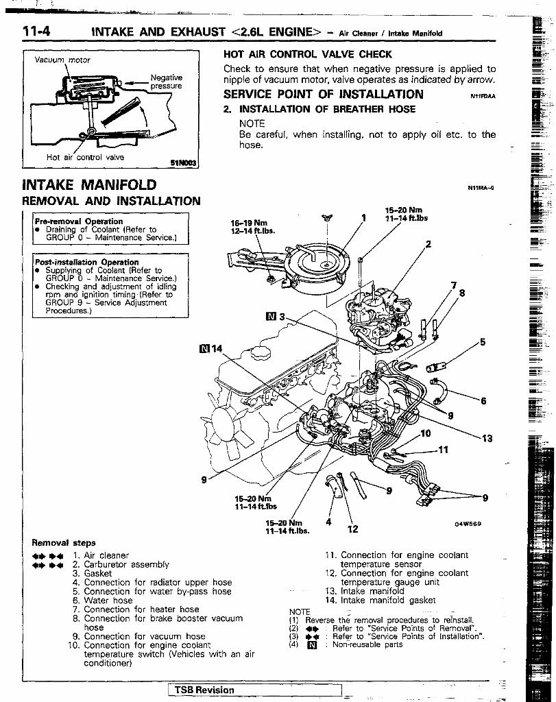
11-4 INTAKE AND EXHAUST <2.6L ENGINE> - Air Cleaner I Intake Manifold
Vacuum motor \
Hot air’control valve
INTAKE MANIFOLD REMOVAL AND INSTALLATlON
Pra-removal Operation l Draining of Coolant (Refer to
GROUP 0 - Maintenance Service.)
Post-installation Operation 0 Supplying of Coolant (Refer to
GROUP 0 - Maintenance Service.) l Checking and adjustment of idling
rpm and ignition timing.(Refer to GROUP 9 - Service Adjustment Procedures.)
Removal steps
+e l + 1. Air cleaner +e l + 2. Carburetor assembly
3. Gasket ^ _
HOT AIR CONTROL VALVE CHECK Check to ensure that when negative pressure is applied to nipple of vacuum motor, valve operates as indicated by arrow.
SERVICE POINT OF INSTALLATION NIWOAA 2. INSTALLATION OF BREATHER HOSE
NOTE Be careful, when installing, not to apply oil etc. to the hose.
m,MI-o
19-19 Nm 12-14ftlbs.
19-20 Nm ,I li”““‘bs
4 049569 11-14ftJbs.
11. Connection for engine coolant temperature sensor
12. Connection for engine coolant 4. Connectton tor racitator upper hose 5. Connection for water by-pass hose 6. Water hose 7. Connection for heater hose 8. Exsuerection for brake booster vacuum
9. Connection for vacuum hose 10. Connection for engine coolant
temperature switch (Vehicles with an air conditioner)
temperature gauge unit 13. Intake manifold 14. Intake manifold gasket
NOTE (I) Reverse the removal procedures to re%all. (2) +e : Refer to “Service Points of Removal”. (3) ++ : Refq to “Service Points of Installation”. (4) q : Non-reusable parts
/ -TSB Revision
INTAKE AND EXHAUST <2.6L ENGINE> - Intake Manifold 11-5
SERVICE POINTS OF REMOVAL 1. REMOVAL OF AIR CLEANER
Refer to P. 113. 2. REMOVAL OF CARBURETOR ASSEMBLY
Refer to GROUP 14 - Carburetor.
INSPECTION NllMcAp
Check the points described below; replace the part if a problem is found. (1) Damage or cracking of any part. (2) Clogging of the negative pressure (vacuum) outlet port, or
clogging of the water or gas passages.
SERVICE POINTS OF INSTALLATION NlllDAC.
2. INSTALLATION OF CARBURETOR ASSEMBLY
Refer to GROUP 14 - Carburetor. 1. INSTALLATION OF AIR CLEANER
Refer to P. 11-3.
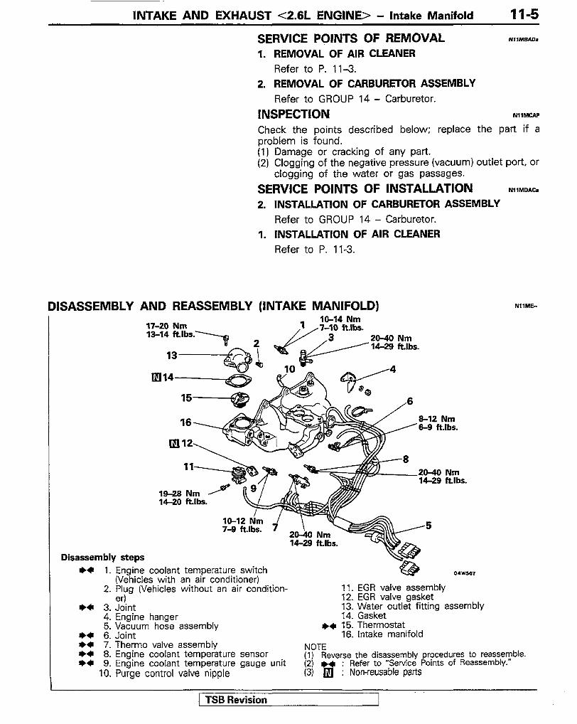
DISASSEMBLY AND REASSEMBLY (INTAKE MANIFOLD)
17-20 Nm XI-14 ft.lbs
1 IO-14 Nm
x7-ill fklhc.
Nm _ _..--.
20-40 ~~~ / 14-28 ft.lbs.
16 al2 Nm 8-8 ft.lbs.
4
-6
19-28 Nm 14-20 Ribs.
Disassembly steps
NIlhE-
++ 1. Engine coolant temperature switch (Vehicles with an air conditipner)
2. F’:g (Vehrcles wrthout an arr condition- 11. EGR valve assembly 12. EGR valve aasket - . I
+C 3. Joint 13. Water o&e? fitting assembly 4. Engine hanger 14. Gasket 5. Vacuum hose assembly I)+ 15. Thermostat
+* 6. Joint 16. Intake manifold l + 7. Therm0 valve assembly NOTE ++ 8. Engine coolant temperature sensor ++ 9. Engine coolant temperature gauge unit
(1) Reverse the disassembly procedures to reassemble. (2) H : Refer to “Service Points of Reassembly.”
10. Purge control valve nipple (3) 0 : Non-reusable parts
I 1 TSB Revision

04W563 I
EXHAUST MANIFOLD REMOVAL AND INSTALLATION
Removal
SERVICE POINTS OF REASSEMBLY 15. INSTALLATION OF THERMOSTAT
Refer to GROUP 7 - Thermostat.
9. APPLKATION OF SEALANT TO ENGINE COOLANT TEMPERATURE GAUGE UNIT/8. ENGlNE COOLANT
.~
TEMPERATURE SENSOR/7. THERM0 VALVE .- ASBEMBLY/8./3./1. JOINT AND ENGINE COOLANT TEMPERATURE SWITCH Ez. E Apply a coating of the specified sealant to the threaded part, and then tighten at the specified torque.
_ =
Specified sealant : 3M ART Part No. 8860 or equivalent
‘K-19 Nm 12-14 ftlbs.
12-15 Nm 9-11 ftlbs..
4S50 Nm 29-36 ft.lbs.
steps ++ ++ 1. Air cleaner
2. Air duct 3. Heat duct 4. Air pipe assembly 5. Reed valve B bracket 6. Exhaust manifold cover 7. Oxygen sensor 8. Self-locking nut 9. Connection for exhaust manifold and
front exhaust pipe
NlfW
10. Gasket 11. Engine hanger 12. Exhaust manifold 13. Exhaust manifold gasket
NOTE (II Reverse the removal procedures to reinstall. (2) l * : RefeT to “Service Points of Removal”. (3) +* : Refer to “Service Points of Installation”. (41 q : Non-reusable parts

INTAKE AND EXHAUST <2.6L ENGINE> - s;z I;$;:; Mufflers 11-7
SERVICE POINTS OF REMOVAL NIINSAb 1. REMOVAL OF AIR CLEANER
Refer to P. 11-3.
INSPECTION EXHAUST MANIFOLD
NIINCAP
Check the exhaust manifold for damage and cracks, and replace it if any defects are found. EXHAUST MANIFOLD GASKET Check for flaking or damage of the gasket.
SERVICE POINTS OF INSTALLATION NIlNOAh 1. INSTALLATION OF AIR CLEANER
Refer to P. 11-3.
EXHAUST PIPES AND MUFFLERS REMOVAL AND INSTALLATION
El0 Nm 4-7 ft.lbs.
40-60 Nm _... Llbs. /I
20-30 Nn
11-18 ft.lbs.
Nm *. .* I 8-8 ft.lbs.
1. Gasket w+ 2. Front exhaust pipe
3. Spring 4. Suspender 5. Hanger bracket
I)* 6. Center exhaust pipe 7. Hanger
** 8. Main muffler ++ 9. Catalytic converter assembly
10. Self-locking nut
NOTE (1) l * : Refer to. “Service Points of Installation”. (2) 0 : Non-reusable parts
I TSB Revisiqn

II-8 INTAKE AND EXHAUST <2.6L ENGINE> - Exhaust Pipes and MuHlers
INTAKE AND EXHAUST <3.OL ENGINE> - specifications
INSPECTION NWICAE l Check the mufflers or pipes for corrosion or damage. @ Check the rubber hangers or suspenders for deterioration
or damage. b Check for gas leakage from mufflers or pipes.
SERVICE POINTS OF INSTALLATION N(lRDAE
2. INSTALLATION OF FRONT EXHAUST PIPE/G. CENTER EXHAUST PIPE/S. MAIN MUFFLER/S. CATALYTIC CON- VERTER ASSEMBLY (1) Temporarily install the front exhaust pipe, the cataalytic
converter assembly the center exhaust pipe, and the main muffler in that order. Caution With temporarily tightened, check to be sure there is no distortion of the hangers.
(2) After fully tightening each exhaust pipe and main muffler, check to be sure there is no contact with the chassis at any place.
INTAKE AND EXHAUST <3.OL ENGINE> SPECIFICATIONS NIICA-I GENERAL SPECIFICATIONS
Items
Air cleaner Element
Exhaust system Front exhaust pipe Muffler Coupling Suspension system
Specifications
Filter paper type
Dual type Expansion resonance type Flat coupling Rubber hangers, O-rings and suspenders
I I I
TORQUE SPECIFICATIONS NIICCI
Items
Air cleaner to body Air duct to fender shield Accelerator cable bracket to air intake plenum EGR pipe attaching bolts to air intake plenum Engine oil filler neck bracket to air intake plenum Throttle body to air intake plenum Air intake plenum to front stay, rear stay Air intake plenum to intake manifold EGR valve to air intake plenum
Nm
8-10 8-10 4-6
15-20 8-l 0
IO-13 1.5-20 15-20 17-26
ftibs.
6-7 6-7 34
11-14 6-7 7-9
II-14 II-14 12-19
[ TSB Revision

INTAKE AND EXHAUST <3.OL ENGINE> - Spectications I Troubleshooting 11-9
[terns Nm ft.lbs.
Fuel high pressure hose to delivery pipe IO-13 7-8 Delivery pipe to intake manifold 7-l 1 5-8 Heater pipe attaching bolts to intake manifold IO-13 7-8 Intake manifold to engine 15-20 11-14 Oxygen sensor 40-50 28-36 Front exhaust pipe to exhaust manifold 30-40 22-29 Front exhaust pipe (L.H.) to front exhaust pipe (R.H.) 2C-30 14-22 Front exhaust pipe (L.H.) to oil pan bracket 20-30 14-22 Front exhaust pipe (R.H.) to catalytic converter I!%25 11-18 Heat protector to exhaust manifold 12-15 9-11 Engine hanger to engine l&22 11-16 Alternator stay to engine 15-22 11-16 Exhaust manifold to engine 15-22 11-16 EGR pipe to exhaust manifold 1 E-20 11-14 Bracket to engine 15-22 11-16 Air iritake plenum stay to bracket 15-20 11-14 Front exhaust pipe to under catalytic converter 15-25 11-18 Under catalytic converter to center exhaust pipe 40-60 29-43 Hanger bracket to suspender 8-12 6-8 Suspender to frame a12 6-9 Center exhaust pipe to main muffler 20-30 14-22 rail pipe to hanger 5-10 4-7 Hanger to frame 5-10 4-7 Tail pipe to main muffler 30-40 22-29 Engine coolant temperature switch IO-14 7-l 0 Engine coolant temperature sensor 2Wzo Id-29 rhermo switch 6-8 4-7 sngine coolant temperature gauge unit IO-12 7-8 rhermo valve assembly 20-40 14-27
SEALANTS AND ADHESIVES N,,CC-B
Items / Specified sealants and adhesives 1 Quantity 1
Engine coolant temperature gauge unit, Engine coolant temperature switch, Engine coolant temperature sensor, Therm0 switch, Therm0 valve assembly and Joint (threaded part)
3M ART Part No. 8660 or equivalent
As required
TROUBLESHOOTING Refer to P. 1 l-3.
TSB Revision

11-10 INTAKE AND EXHAUST <3.OL ENGINE> - Air Cleaner
AIR CLEANER N,WA-I REMOVAL AND INSTALLATION
S-IO Nm ,6-7 ft.lbs.
16 15
-8-10 Nm 6-7 ft.lbs.
4
Removal steps 1. Connection of air flow sensor
connector 2. Breather hose 3. Air intake hose .~ 4. Air cleaner 5. Air duct “8” 6. Air duct “A” 7. Air cleaner cover 8. Air cleaner element 9. Air flow sensor assembly
10. Air flow sensor asket 17. Noise reduction 9. ilter 12. Cover 13. Grommet 14, Air cleaner body 15. Insulator 16. Collar
NOTE (I) Reverse the removal procedures to reinstall. (2) q : Non-reusable parts
INSPECTION NIIFCAE e Check the air cleaner body, cover or packing for deforma-
tion, corrosion or damage. l Check the air cleaner element for clogging, contamination
or damage. If element is slightly clogged, remove dust by blowing air from inside of element.
AIR-FLOW SENSOR CHECK For inspection of air-flow sensor, refer to GROUP 14 - Air- Flow Sensor Check. _ ._
/ TSB Revision --~~ z

INTAKE AND EXHAUST <3.OL ENGINE> - Air intake Plenum II-11
AIR INTAKE PLENUM REMOVAL AND INSTALLATION
Removal steps 1. Connection for air intake hose 2. Accelerator cable adjusting bolts 3. Connection for throttle control cable
~~~~;cles with an automatrc transmts-
4. Connection for accelerator cable 5. Connection for vacuum hose 6. Connection for brake booster vacuum
hose 7. EGR temperature sensor connector 8. Connection for vacuum hose 9. EGR pipe attaching bolts
10. Gasket
05w532
16. Throttle body gasket 17. Bolts 18. Bolts and nuts 19. Air intake plenum 20. Air intake plenum gasket 21. EGR valve 22. EGR gasket 23. Air intake plenum front stay
+*
11. Connection for high tension cable 12. Ignition coil
24. Air intake plenum rear stay
13. Engine oil filler neck bracket NOTE
14. Connection for PCV hose (I) Reverse the removal procedures to reinstall.
15. Throttle body assembly (2) ** : Refer to “Service Points of Removal”. (3) q : Non-reusable parts
SERVICE POINTS OF REMOVAL NIIOBAS 15. REMOVAL OF THE THROTTLE BODY ASSEMBLY
Take out the throttle body installation bolts, taking care not to disturb the throttle body during the operation. NOTE Leave the water hoses attached to the throttle body assembly.
INSPECTION NIIUCAC Check the air intake plenum for damage and cracks and replace it if any defects are found.
TSB Revision

i i -~--cc. --. waif=_ ,_- ;---*ihi -~, .--
11-12 INTAKE AND EXHAUST <3.OL ENGINE> - intake Manifold
INTAKE MANIFOLD REMOVAL AND INSTALLATION
~g!GJEgJ;;;, ,4 _ l Reduction of the Fuel Line internal
Post-installation Operation l Filling of Engine Coolant
$;$r to GROUP 0 - Maintenance Ser-
o Adjustment otAccelerator Cable (Refer to GROUP 14 - Engine Control.)
0 Inspection of fuel pressure (Refer to GROUP 14 - MPI System.)
E-20 Nm 11-14 ft.lbs aa
IS 4-6Nm 19 n/ 34 ft.lbs.
Removal steps 1. Connection for air intake hose 2. Throttle position sensor connector 3. Stepper motor connector 4. Accelerator cable adjusting bolts 5. Connection for throttle control cable
W&es with an automatic transmis-
6. Connection for accelerator cable 7. Connection for water hoses 8. EGR temperature sensor connector 9. Connection for vacuum hose
10. Connection for brake booster vacuum hose
11. Connection for high tension cable
12. Ignition coil 13. En@ne oil filler neck bracket 14. Cofinection for PCV hose 15. Connection for vacuum hose 16. EGR pipe attaching bolts 17. Gasket 18. Boits 19. Bolts and nuts 20. Air intake plenum and throttle body 21. Air intake plenum gasket
NOTE (lj Reverse the- removal procedures to reinstall. (2) a : Non-reusable parts
/ TSB Revision -

INTAKE AND EXHAUST <3.OL ENGINE> - Intake Manifold II-13
IO-13 Nm 7-9 ftlbs.
rnw531
22. Connection for fuel high pressure hose 23. Connection for fuel return hose 24. Vacuum hose 25. Connection for control harness 26. Deliven/ pipe, fuel injector and pressure
regulator 27. Vacuum hose and pipe assembly 28. Connection for engine coolant
temperature gauge unit connector 29. Connection for engine coolant
temperature switch connector (Vehicles with an air conditioner)
30. Connection for engine coolant temperature sensor connector
31. Connection for therm0 switch connector (Vehicles with an auto- matic transmission)
32. Radiator upper hose 33. Connection for water by-pass hose 34. Heater pipe attaching bolts
35. Gasket 36. Intake manifold 37. Intake manifold gasket 38. Water outlet fitting assembly 39. Gasket
l + 40. Thermostat ++ 41. Engine coolant temperature switch
(Vehicles with an air conditioner) ++ 42. Engine coolant temperature sensor ++ 43. Therm0 switch (Vehicles with an
automatic transmission) ++ 44. Engine coolant temperature gauge unit ++ 45. Therm0 valve assembly
NOTE (1) Reverse the removal procedures to reinstall. (2) ++ : Refer to “Service Points of Removal”. (3) ** : Refer to “Service Points of Installation”. (4) q : Non-reusable parts
/ TSB Revision

INTAKE AND EXHAUST <3.OL ENGINE> - Intake Manifold
SERVICE POINTS OF REMOVAL NI,MBAL 22. DISCONNECTION OF FUEL HIGH PRESSURE HOSE
Caution Cover fuel pipe line with rag after relieving pressure as certain pressure may still remain.
26. REMOVAL OF DELIVERY PIPE, FUEL INJECTOR AND PRESSURE REGULATOR Remove delivery pipe with fuel injector and pressure regulator. Caution Do not drop injector when removing delivery pipe.
INSPECTION INTAKE MANIFOLD Check the points described below; replace the part if a problem is found. (I) Check for damage or cracking of any part. (2) Check for clogging of the water passages.
SERVICE IfOlNTS OF INSTALLATION NIlUDIT 45APPLlCATlON OF SEALANT TO THERM0 VALVE
ASSEMBLYbl4. ENGINE COOLANT TEMPERATURE GAUGE UNIT/43. THERM0 SWITCH/42. ENGINE COOLANT TEMPERATURE SENSOW41. ENGINE COOLANT TEMPERATURE SWITCH Refer to P. 11-6.
46. INSTALLATION OF THERMOSTAT Refer to GROUP 7 - Thermostat.
1 TSB Revision

INTAKE AND EXHAUST <3.OL ENGINE> - Exhaust Manifold 11-15
EXHAUST MANIFOLD NIINA-I REMOVAL AND INSTALLATION
Pre-removal Operation 30-40 Nm l Removal of Under Guard and Snow 22-29 klbs. 1
C. ,3rA I \ 40-50 Nm
I I Snow Guard
uucu ” ($&fe,to GROUP 23 - Under I \
._ -- ._... /, ,26-36 ft.lbs.
Post-installation Operation . Installation of Under Guard and
GROUP 23 - Under
12-15 Nm 6-11 ft.lbs.
\ 15-22 Nm 11-16 ft.lbs.
655-25 Nm
i 11-18 klbs.
I 15b2 Nm 11-16 ft.lbs.
15-k Nm 11-16 ftlbs.
I 12-15 Nm 9-11 ft.lbs.
I OSW528
Removal steps of exhaust manifold (Right) 1. Oxygen sensor 2. Front exhaust pipe (L.H.) 3. Front exhaust pipe (R.H.) 4. Gasket 5. Air duct 6. Heat protector 7. Engine hanger 8. Alternator stay 9. Exhaust manifold
10. Gasket
Removal steps of exhaust manifold (Left) 2. Front exhaust pipe (L.H.) 4. Gasket
11. EGR pipe 12. EGR gasket 13. Heat protector 14. Air intake plenum 15. Bracket 16. Exhaust manifold 17. Gasket
NOTE (1) Reverse the removal procedure to reinstall. (2) m : Non-reusable parts
I TSB Revision

II-16 INTAKE AND EXHAUST <3.OL ENGINE> - Exhaust Pipes and Mufflers
EXHAUST PIPES AND MUFFLERS [EMOVAL AND INSTALLATION E-12 Nm
6-9 ft.Ibs.
Prs-removal Operation l Removal of Under Guard and Snow
Guard (R&;,$ GROUP 23 - Under
1. Gasket 2. Self-locking nut
I)+ 3. Front exhaust pipe (L.H.) l + 4. Front exhaust pipe (R.H.)
5. Oxygen sensor ^^. 6. aprmg
I)+ 7. Catalytic converter assembly ^ 8. Hanger bracket 9. Suspender
e)+ 10. Center exhaust pipe e+ 11. Main muffler
l Installation of Under Guard and
12. O-ring 13. Hanger
l I 14. Tail pipe (2 d6or vehicles) +* 15. Tail pipe (4 door vehicles) i
14
E-10 Nm 4-7 ft.lbs.
05W524
NOTE (1) *4 : Refer to “Service Point? of Installation”. (2) •l : Non-reusable parts
INSPECTION r4I,RcAJ o Check the mufflers or pipes for corrosion or damage. l Check the rubber hangers, suspenders and O-rings for
deterioration or damage. l Check for gas leakage from mufflers or pipes
SERVICE POINTS OF INSTALLATION NImrJAJd 3./4. INSTALLATION OF FRONT EXHAUST PIPE/
7. CATALYTIC CONVERTER ASSEMBLY/IO. CENTER EXHAUST PIPE/ll. MAIN MUFFLER/l4./15. TAIL PIPE (1) Temporarily install the front exhaust pipe, the catalytic
converter assembly, the center exhaust pipe, the main muffler and tail pipe in that order.
Caution With temporarily tightened, check to be sure there is no distortion of the hangers.
(2) After fully tightening each exhaust pipe and main muffler, check to be sure there is no contact with the chassis at any place.
1 TSB Revision I