iHFG part b complete - Health Facility Guidelines
24
Planning International Health Facility Guidelines © TAHPI Part B: Version 5 2017 Page 7 4 Planning 1 Site Development The location and development of the site shall be in accordance with the requirements of the Urban Planning Council and the local Municipality. Below we have summarised the main criteria to be considered when developing a site, accommodating a health facility. Environmental Impact The aesthetics and form of a health facility shall be sympathetic with its immediate environment, either built or natural; for example domestic scale and treatments where built in a residential area. The building should enhance the streetscape. Note: This is not a mandatory requirement but is highly recommended. Consideration should also be given to the siting of a health facility to ensure that it is accepted as an asset by the community, and not thought of as an imposition and inconvenience on the neighbourhood. Landscaping A suitable landscaping scheme shall be provided to ensure that the outdoor spaces are pleasant areas in which patients, visitors and staff may relax. The scheme should also ensure that the buildings blend into the surrounding environment, built or natural. Water conservation should be a consideration when designing layouts and selecting plants. The use of mains water for reticulation is restricted. The local authority on water supply should be consulted for current regulations. Site Grading The balance of a health facility site not covered by buildings should be graded to facilitate safe movement of the public and staff. Where this is not possible, access should be restricted. Public Utilities Impact on existing local service networks may be substantial. In establishing a health facility on any site, the requirements and regulations of authorities regulating water, electricity, gas, telephones, sewerage and any other responsible statutory or local authority must be complied with. Structural requirements If the site is low lying, on the side of a hill, or partly consists of rock then structural engineering advice should be sought at an early stage to minimise future drainage or settlement problems. 2 Masterplan Development Planning relationships and the use of planning models The planning of health facilities requires general knowledge of the appropriate relationships between the various components. Certain components (also referred to as Functional Planning Units or FPUs) need to be adjacent or close to other components. Most components must be accessible independently without having to go through other components. In short, the planning of a health facility requires a certain logic which is derived from the way the facility functions. Good Planning Relationships: ▪ Increase the efficiency of operation ▪ Promote good practice and safe health care delivery
Transcript of iHFG part b complete - Health Facility Guidelines

Planning
International
Health Facility Guidelines © TAHPI
Part B: Version 5 2017
Page 7
4 Planning 1 Site Development The location and development of the site shall be in accordance with the requirements of the Urban Planning Council and the local Municipality. Below we have summarised the main criteria to be considered when developing a site, accommodating a health facility. Environmental Impact The aesthetics and form of a health facility shall be sympathetic with its immediate environment, either built or natural; for example domestic scale and treatments where built in a residential area. The building should enhance the streetscape. Note: This is not a mandatory requirement but is highly recommended. Consideration should also be given to the siting of a health facility to ensure that it is accepted as an asset by the community, and not thought of as an imposition and inconvenience on the neighbourhood. Landscaping A suitable landscaping scheme shall be provided to ensure that the outdoor spaces are pleasant areas in which patients, visitors and staff may relax. The scheme should also ensure that the buildings blend into the surrounding environment, built or natural. Water conservation should be a consideration when designing layouts and selecting plants. The use of mains water for reticulation is restricted. The local authority on water supply should be consulted for current regulations. Site Grading The balance of a health facility site not covered by buildings should be graded to facilitate safe movement of the public and staff. Where this is not possible, access should be restricted. Public Utilities Impact on existing local service networks may be substantial. In establishing a health facility on any site, the requirements and regulations of authorities regulating water, electricity, gas, telephones, sewerage and any other responsible statutory or local authority must be complied with. Structural requirements If the site is low lying, on the side of a hill, or partly consists of rock then structural engineering advice should be sought at an early stage to minimise future drainage or settlement problems. 2 Masterplan Development Planning relationships and the use of planning models The planning of health facilities requires general knowledge of the appropriate relationships between the various components. Certain components (also referred to as Functional Planning Units or FPUs) need to be adjacent or close to other components. Most components must be accessible independently without having to go through other components. In short, the planning of a health facility requires a certain logic which is derived from the way the facility functions. Good Planning Relationships: ▪ Increase the efficiency of operation ▪ Promote good practice and safe health care delivery
Planning
International
Health Facility Guidelines © TAHPI
Part B: Version 5 2017
Page 8
▪ Minimise recurrent costs ▪ Improve privacy, dignity and comfort ▪ Minimise travel distances ▪ Support a variety of good operational policy models ▪ Allow for growth and change over time. Inappropriate Planning Relationships: ▪ Result in duplication and inefficiency ▪ May result in unsafe practices ▪ Increase running costs ▪ May result in reduced privacy, dignity and comfort ▪ Increases travel distance or force un-necessary travel ▪ Result in lack of flexibility to respond to future growth and change ▪ May limit the range of operational possibilities. Planning Models: The planning of a complex health facility is based on applying commonly recognised "good relationships" as well as taking into consideration site constraints and conformity with various codes and guidelines. In theory it is possible to go back to the basics every time. In practice however, designers soon discover that this is an inefficient way of arriving at appropriate planning solutions. Just as in other buildings types e.g. hotels and shopping centres, health facilities have over time evolved around a number of workable Planning Models. These can be seen as templates, modules, prototypes or patterns for the design of new facilities. These Guidelines include a number of flow diagrams, also referred to as Functional Relationship Diagrams which represent Planning Models for various Functional Planning Units (FPUs). The flow diagrams are referred to in the appropriate sections of these Guidelines. They cover not only internal planning and relationships within the FPUs, but also relationships between FPUs. Designers may use these diagrams to set out the various components and then manipulate them into the appropriate shapes to suit the site constraints. Designers are encouraged to see the overall design as a model. A good health facility plan usually can be reduced to a basic flow diagram. If the diagram has clarity, is simple and logical, as demonstrated in the FPUs in these Guidelines, it probably has good potential for development. A skilled designer will use these planning models to assemble the requirements of a health facility on the site without compromising functionality. If on the other hand the model is too hard to reduce to a simple, clear and logical flow diagram, it should be critically examined. It is not sufficient to satisfy immediate or one-to-one relationships. Similarly, it may not be sufficient to satisfy only a limited, unusual or temporary operational policy. It is more important to incorporate planning relationships that can satisfy multiple operational policies due to their inherent simplicity and logic. Masterplanning In the health care industry, the term “Masterplan” has different meanings in different contexts. The most common use of the term “Masterplan” refers to words, diagrams and drawings describing the "global arrangement of activities" in a health facility with particular emphasis on land use, indicating growth and change over time. Under the above definition, a Masterplan is a fundamental planning tool to identify options for the current needs as well as projected future needs. Its purpose is to guide decision making for clients and designers. Health facility owners and designers are encouraged to prepare a Masterplan before any detailed design is undertaken. A Masterplan can be prepared in parallel with detailed briefing, so that valuable feedback can be obtained regarding real world opportunities and constraints. Ideally, a successful Masterplan will avoid wrong long term strategic decisions, minimise abortive work,
Planning
International
Health Facility Guidelines © TAHPI
Part B: Version 5 2017
Page 9
prevent future bottlenecks and minimise expectations that cannot be met in the given circumstances. A Masterplan diagram is typically a simplified plan showing the following: ▪ The overall site or section of the site relating to the development ▪ Departmental boundaries for each level related to the development ▪ Major entry and exit points to the site and the relevant departments ▪ Vertical transportation including stairs and lifts ▪ Main inter-departmental corridors (arterial corridors) ▪ Location of critical activity zones within departments but without full detail ▪ Likely future site development ▪ Areas (if any) set aside for future growth and change ▪ Arrows and notes indicating major paths of travel for vehicles, pedestrians, goods and beds ▪ Services masterplan showing the engineering impact, plant locations, availability of services
and future demand. Masterplan diagrams and drawings should be prepared for several options (typically 3) to an equal level of resolution and presentation so that each option reaches its maximum potential. Only then a decision maker is in a position to compare options on equal terms. The above diagrams and drawings are typically accompanied by a report covering the following headings as a minimum: ▪ Project description ▪ Outline brief ▪ Opportunities and constraints ▪ Options considered ▪ Evaluation criteria ▪ Evaluation of the options including cost impact (if any) ▪ Recommended option ▪ Executive summary and recommendation. The exact deliverables for a Masterplan can adapted to the nature of the project. The most typical additional deliverables are listed below, allowing clients to refer to them by name and by reference to these Guidelines: ▪ Stacking Plans- This is typically used for locating departments in major multistorey
developments where the shell is already well defined. ▪ Master Concept plan - This is typically used as a further development of the preferred
Masterplan option so that the design implications can be further tested and priced. ▪ Staging Plan - A staging plan shows a complete Masterplan defined for each stage of the
development rather than simply a zone allocation for future works. ▪ Strategic Plan - A Strategic Plan refers to higher level "what if" studies, providing a range of
development scenarios. These may include the use of alternate sites, private-public collocation, purchase versus lease, alternative operational policies etc.
Planning Policies Planning policies refer to a collection of non-mandatory guidelines that may be adopted by health facility designers or owners. These policies generally promote good planning, efficiency and flexibility. The planning policies below are included in these Guidelines so that in the process of briefing, designers or clients can simply refer to them by name or require compliance from others.
Loose Fit
Loose Fit is the opposite of Tight Fit. This policy refers to a type of plan which is not so tightly configured around only one operational policy that it is incapable of adapting to another. In Health Care, operational policies change frequently. The average cycle seems to be around 5 years. It may be a result of management change, government policy change, turn-over of key staff

Planning
International
Health Facility Guidelines © TAHPI
Part B: Version 5 2017
Page 10
or change in the market place. On the other hand, major health facilities are typically designed for 30 years but tend to last more than 50 years. This immediately presents a conflict. If, for example, a major hospital is designed very tightly around the operational policies of the day or the opinion of a few individuals that may leave at any time, then a significant investment may be at risk of early obsolescence. The Loose Fit Planning Policy refers to planning models which can not only adequately respond to today's operational policy but have the inherent flexibility to adapt to a range of alternative, proven and forward looking policies. At macro Level, many of the commonly adopted health facility planning models, including those in the enclosures to these Guidelines, have proven flexible in dealing with multiple operational policies. At micro level, designers should consider simple, well proportioned, regular shaped rooms with good access to simple circulation networks that are uncomplicated by a desire to create interest. Interior features should not be achieved by creating unnecessary complexity.
Change by Management
This concept refers to plans which allow for changes in operating mode as a function of management rather than physical building change. For example, two Inpatient Units can be designed back to back so that a range of rooms can be shared. The shared section may be capable of isolation from one or the other Inpatient Unit by a set of doors. This type of sharing is commonly referred to as Swing Beds. It represents a change to the size of one Inpatient Unit without any need to expand the unit or make any physical changes. The same concept can be applied to a range of planning models to achieve greater flexibility for the management. Also see other planning policies in this section.
Overflow Design
Some functions can be designed to serve as overflow for other areas that are subject to fluctuating demand. For example, a waiting area for an Emergency Unit may be designed so that it can overflow into the hospital’s main entrance waiting area. An Emergency Unit Procedure Room or a Birthing Room may be designed specifically to provide an emergency operating room for caesarean sections in case the standard allocated operating room is not available. Any area that includes bed bays such as an Emergency Unit may be designed to absorb the available open space and provide room for additional beds in case of natural disasters.
Progressive Shutdown
Even large facilities may be subject to fluctuating demand. It is desirable to implement a Progressive Shutdown policy to close off certain sections when they are not in use. This allows for savings in energy, maintenance and staff costs. It also concentrates the staff around patients and improves communication and security. In designing for progressive shutdown, designers must ensure: ▪ None of the requirements of these Guidelines are compromised in the remaining open
sections ▪ The open sections comply with other statutory requirements such as fire egress ▪ The open patient care sections maintain the level of observation required by these guidelines ▪ In the closed sections, lights and air-conditioning can be shut off independently of other
areas ▪ The closed sections are not required as a thoroughfare for access to other functions ▪ Nurse Call and other communication systems can adapt to the shut-down mode appropriately ▪ The shut-down strategy allows access to items requiring routine maintenance.
Planning
International
Health Facility Guidelines © TAHPI
Part B: Version 5 2017
Page 11
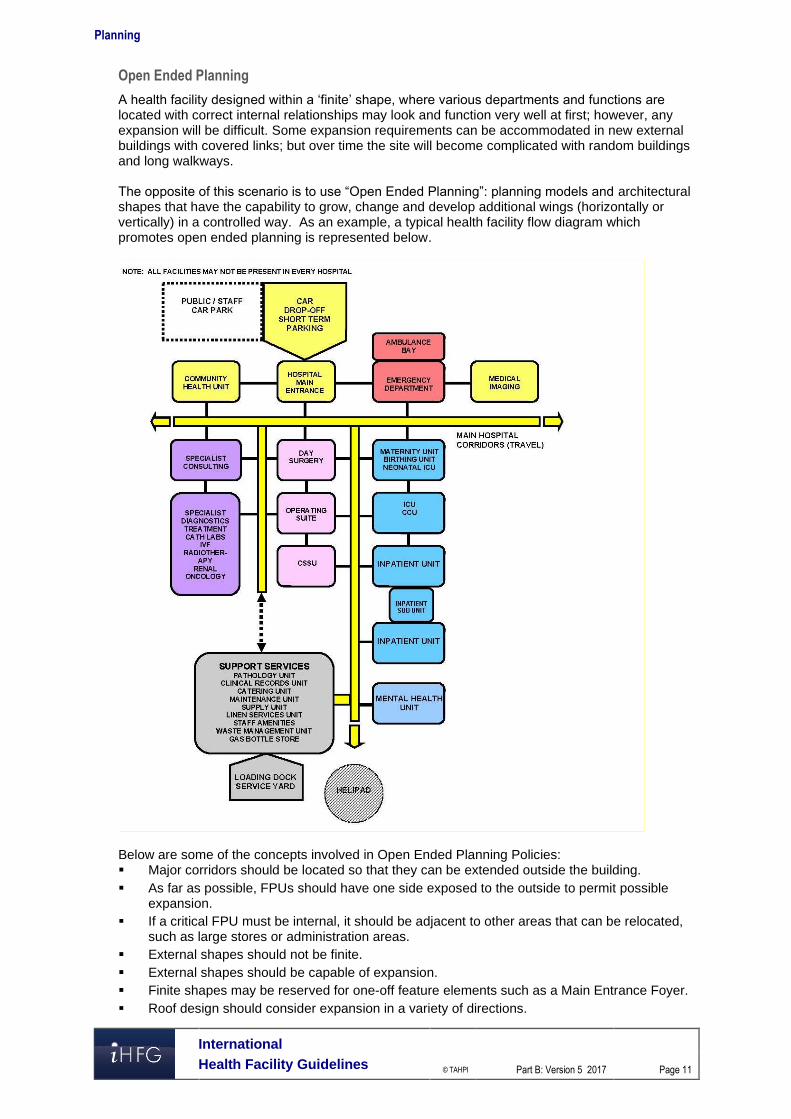
Open Ended Planning
A health facility designed within a ‘finite’ shape, where various departments and functions are located with correct internal relationships may look and function very well at first; however, any expansion will be difficult. Some expansion requirements can be accommodated in new external buildings with covered links; but over time the site will become complicated with random buildings and long walkways. The opposite of this scenario is to use “Open Ended Planning”: planning models and architectural shapes that have the capability to grow, change and develop additional wings (horizontally or vertically) in a controlled way. As an example, a typical health facility flow diagram which promotes open ended planning is represented below.
Below are some of the concepts involved in Open Ended Planning Policies: ▪ Major corridors should be located so that they can be extended outside the building. ▪ As far as possible, FPUs should have one side exposed to the outside to permit possible
expansion. ▪ If a critical FPU must be internal, it should be adjacent to other areas that can be relocated,
such as large stores or administration areas. ▪ External shapes should not be finite. ▪ External shapes should be capable of expansion. ▪ Finite shapes may be reserved for one-off feature elements such as a Main Entrance Foyer. ▪ Roof design should consider expansion in a variety of directions.
Planning
International
Health Facility Guidelines © TAHPI
Part B: Version 5 2017
Page 12
▪ Avoid FPUs that are totally land-locked between major corridors. ▪ Stairs should not be designed to block the end of major corridors. ▪ The overall facility flow diagram should be capable of linear or radial expansion whilst
keeping all the desirable relationships intact. ▪ Fixed internal services such as plant rooms, risers, service cupboards should be placed
along major corridors rather than in the centre of FPUs. Open Ended Planning Policies can be applied to entire facilities as well as individual FPUs.
Modular Design
This is the concept of designing a facility by combining perfectly designed standard components. For example a designer may create a range of Patient Bedrooms, a range of utility rooms and other common rooms that are based on a regular grid such as 600 mm. These rooms can then be combined to create larger planning units such as an Inpatient Unit. The Inpatient Unit can then be used as a module and repeated a number of times as required. This approach, in the hands of a skilled designer has many benefits. Modules can be designed only once to perfection and repeated throughout the facility. No redesign is necessary to adjust to different planning configurations. Instead the plan is assembled to adapt to the modules. Errors in both design and construction can therefore be minimised. The opposite to this approach is to start from a different architectural shape for each FPU, divide it into various shapes for the rooms, then design the interior of each room independently. This approach, in the hands of a skilled designer can also result in satisfactory solutions, but at a higher risk of errors and at a greater cost. For example, in a typical health facility, one might find 10 Dirty Utility Rooms which are entirely different. Modular Design should not necessarily be seen as a limitation to the designer's creativity, but a tool to achieve better results. Designers are encouraged to consult with clients and user groups to agree on perfect modules, and then adopt them across all FPUs.
Universal Design
This concept is similar to Modular Design. Universal Design refers to Modules (or standard components) designed to perform multiple functions by management choice. For example, a typical patient single bedroom can be designed to suit a variety of disciplines including Medical/ Surgical/ Maternity and Orthopaedics. Such a room can be standardised across all compatible Inpatient Units. This will permit a change of use between departments if the need arises. Such Universal Design must take into account the requirements of all compatible uses and allow for all of them. The opposite of this policy is to "specialise" the design of each component to the point of inflexibility. Other examples of Universal Design are as follows: ▪ Universal Operating Rooms which suit a range of operations ▪ Bed cubicles in Day Surgery which suit both Pre-op and Post-op ▪ Offices which are standardised into only a limited number of types for example 9 m2 and 12
m2 ▪ Toilets may all be designed for disabled access or as unisex. The main point of Universal Design is to resist unnecessary variation in similar components, where the change in functionality can be accommodated in one standard design.
Single Handing
It is common design practice to design identical and adjoining planning modules in mirror image. This is most common in the assembly of Patient Bedrooms with Ensuites. It is commonly believed that this is also more economical.
Planning
International
Health Facility Guidelines © TAHPI
Part B: Version 5 2017
Page 13
The concept of Single Handing is the exact opposite. Single Handing refers to situations where mirror image (Handing) may not be necessary. In areas requiring a high level of staff training, such as in operating suites, it may be more appropriate to "hand" all key rooms in identical manner. This makes the task of staff training easier and may also reduce the possibility of mistakes. In a hypothetical example, a staff member entering any operating room, regardless of its location and approach from corridor will find the service panel on the left, X-ray viewer on the right and the door to the Sterile Stock Room in the front. In another example, at micro level, medical gases may always be located to the left side of patient’s bedhead regardless of the direction of approach. Note: Single Handing is a matter of individual choice and may not suit all conditions.
Natural Disaster
All health facilities should be capable of continued operation during and after a natural disaster, except in instances where a facility sustains primary impact. This means that special design consideration is needed to protect essential services such as emergency power generation, heating and/or cooling systems, water supply (if applicable), etc. Typical problems such as disruption to public utilities such as water or sewer mains and energy supplies, may affect the operation of onsite services. Appropriate construction detailing and structural provision shall be made to protect occupants and to ensure continuity of essential services in areas where there is a history of earthquakes, cyclones, flooding, bushfires or other natural disasters. Consideration shall be given to possible flood effects when selecting and developing a site. Where possible, facilities shall NOT be located on designated flood plains. Where this is unavoidable, take extra care when selecting structural and construction methodology, and incorporate protective measures against flooding into the design. Facilities shall be designed and constructed to withstand the minimum earthquake design loads on structures. In cyclonic areas, special attention shall be given, not only to protection against the effects of the direct force of wind (structural detailing, special cladding fixings, cyclonic glazing etc.), but also against such things as wind generated projectiles (trees, cladding, fencing etc.) and localised flooding. In all cases, effective long range communications systems, which do not rely on ground lines to function, are essential. Consultation with Emergency Services is recommended to ensure arrangements are in place for emergency long range communications assistance in the event of emergency situations or a major disaster. 3 Local Design Regulations Typical Design factors for Health facilities depending on local customs and traditions may include the following ▪ Access to Recovery areas for relatives ▪ Separation of male and female recovery areas ▪ Separation of male and female waiting areas ▪ Larger family waiting areas ▪ Prayer room on each floor ▪ Independent male and female Inpatient Unit accommodation.
Planning
International
Health Facility Guidelines © TAHPI
Part B: Version 5 2017
Page 14
Prayer Rooms
The typical hospital facility should respect the local customs of the population. Prayer rooms on each floor may be required. Separate prayer rooms for male and female may be required. The following consideration should be given to prayer rooms. ▪ Location of the prayer room should be in an accessible area but away from noise, distraction
and heavy clinical traffic. ▪ Orientation of the prayer room is important; appropriate location of entry into the prayer room
is essential. ▪ Airlock to the prayer room is desirable; this may accommodate hand basin for ablution, shoe
racks, bag lockers and coat hooks as deemed necessary. ▪ Appropriate finish on the floor and walls is desirable ▪ Windows are desirable. 4 Floor Area Measurement Methodology, Definitions and Diagrams Within these Guidelines, Room areas, Departmental boundaries, Travel and Engineering are defined and calculated according to the following standards. How to measure floor areas To measure drawings, the following measurement technique will apply.
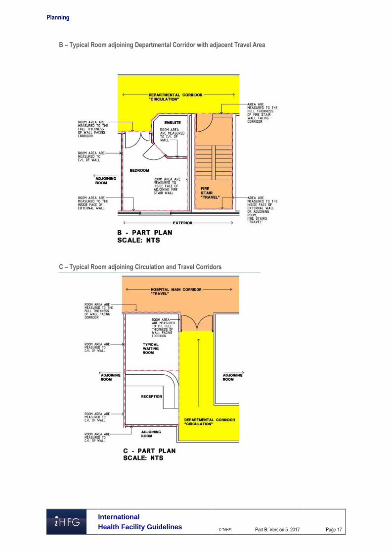
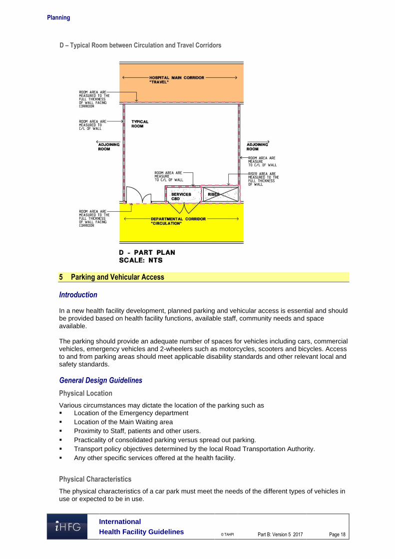
Rooms
Room areas are measured as follows: ▪ To the inside face of outside walls ▪ To centre of walls to adjoining rooms ▪ To the full thickness of corridor walls facing rooms ▪ To the centre of departmental boundary walls (except where boundary wall adjoins a
corridor). Areas not included are: ▪ Circulation % (represented by Departmental corridors) ▪ Service risers, Service cupboards and Plant Rooms ▪ Fire Hose Reels, Fire Stairs, Lift Shafts.
Departments
The gross FPU (Departmental) area is the sum of the room areas within the FPU plus circulation – internal corridors, measured as follows: ▪ FPU areas are measured to the face of corridor walls ▪ To the inside face of outside walls. Areas not included are: ▪ Service Risers, Service Cupboards and Plant Rooms ▪ Fire Hose Reels, Fire Stairs ▪ Lift Shafts.
Travel
Travel includes: ▪ Corridors between Departments (FPUs), measured as follows: ▪ To the face of corridor walls ▪ To the inside face of outside walls ▪ Stairs including Fire Stairs ▪ Internal Fire Stairs and ramps. Areas not included are: ▪ Service risers and cupboards
Planning
International
Health Facility Guidelines © TAHPI
Part B: Version 5 2017
Page 15
▪ Fire Hose Reels, Lift Shafts ▪ Plant Rooms.
Engineering
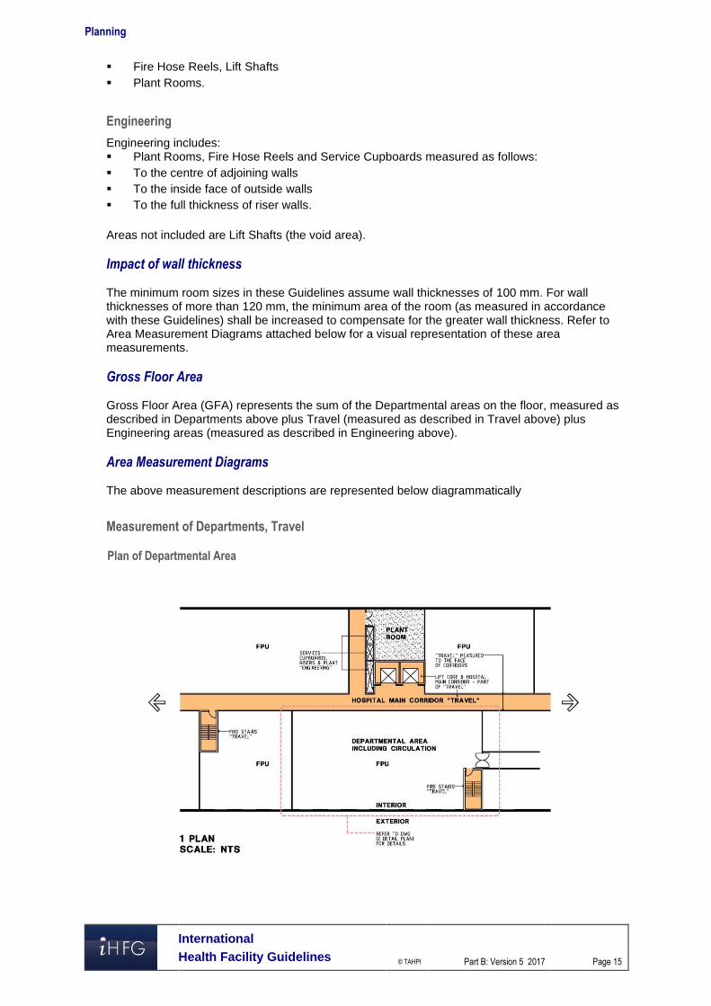
Engineering includes: ▪ Plant Rooms, Fire Hose Reels and Service Cupboards measured as follows: ▪ To the centre of adjoining walls ▪ To the inside face of outside walls ▪ To the full thickness of riser walls. Areas not included are Lift Shafts (the void area). Impact of wall thickness The minimum room sizes in these Guidelines assume wall thicknesses of 100 mm. For wall thicknesses of more than 120 mm, the minimum area of the room (as measured in accordance with these Guidelines) shall be increased to compensate for the greater wall thickness. Refer to Area Measurement Diagrams attached below for a visual representation of these area measurements. Gross Floor Area Gross Floor Area (GFA) represents the sum of the Departmental areas on the floor, measured as described in Departments above plus Travel (measured as described in Travel above) plus Engineering areas (measured as described in Engineering above). Area Measurement Diagrams The above measurement descriptions are represented below diagrammatically
Measurement of Departments, Travel
Plan of Departmental Area
Planning
International
Health Facility Guidelines © TAHPI
Part B: Version 5 2017
Page 16
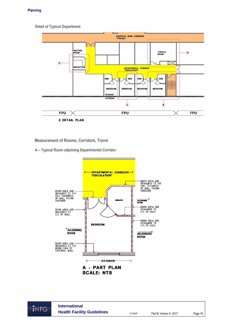
Detail of Typical Department
Measurement of Rooms, Corridors, Travel
A – Typical Room adjoining Departmental Corridor
Planning
International
Health Facility Guidelines © TAHPI
Part B: Version 5 2017
Page 17
B – Typical Room adjoining Departmental Corridor with adjacent Travel Area
C – Typical Room adjoining Circulation and Travel Corridors
Planning
International
Health Facility Guidelines © TAHPI
Part B: Version 5 2017
Page 18
D – Typical Room between Circulation and Travel Corridors
5 Parking and Vehicular Access Introduction In a new health facility development, planned parking and vehicular access is essential and should be provided based on health facility functions, available staff, community needs and space available. The parking should provide an adequate number of spaces for vehicles including cars, commercial vehicles, emergency vehicles and 2-wheelers such as motorcycles, scooters and bicycles. Access to and from parking areas should meet applicable disability standards and other relevant local and safety standards. General Design Guidelines
Physical Location
Various circumstances may dictate the location of the parking such as ▪ Location of the Emergency department ▪ Location of the Main Waiting area ▪ Proximity to Staff, patients and other users. ▪ Practicality of consolidated parking versus spread out parking. ▪ Transport policy objectives determined by the local Road Transportation Authority. ▪ Any other specific services offered at the health facility.
Physical Characteristics
The physical characteristics of a car park must meet the needs of the different types of vehicles in use or expected to be in use.
Planning
International
Health Facility Guidelines © TAHPI
Part B: Version 5 2017
Page 19
For private and emergency vehicles, the car park or drop off areas should adhere to local building authority guidelines. For emergency areas, designated ambulance drop-off and parking is essential for the safety and well-being of patients and staff. Clear access ways and designated parking spots shall be demarcated to avoid misuse. For commercial and service vehicles such as delivery and waste management trucks, loading docks should be designed compatible with the type of vehicles to be used or expected to be used in the future. Traffic controls may need to be provided to segregate vehicles according to their use. For example loading/ unloading areas for a ‘Clean’ delivery truck and a ‘Dirty’ waste management truck. Similarly access points and access ways through the site need to be designed such that patient access does not interfere with emergency and service vehicle access.
Disabled Access Parking
All access to and from the car park will need to adhere to applicable disability guidelines. Parking spaces for use by people with disabilities should be in accordance with such guidelines. A parking space for a person with disability should consist of an unobstructed area having a firm and level surface with a fall not exceeding minimum requirements of the local disability code. Space width and overlap allowances also need to be in accordance with such codes. A continuous, accessible path of travel should be provided between each parking space to an accessible entrance/lift. Parking spaces should be identified by a sign incorporating the international symbol of access for people with disabilities.
Community Safety
Car parking and vehicular access ways should provide a safe environment for its users. Clear sightlines should be provided throughout the car parking areas to enhance safety and avoid confusion. Car parks should be directly linked to accessible pedestrian pathways linking directly to the main building or reception areas. Adequate lighting is essential after hours for patients and staff to access their vehicles. Communication and security systems may be installed in large car parks depending on the location, function and layout. Adequate traffic controls may be required to safely navigate pedestrian and vehicular traffic through the parking area. This could be achieved through signage or other electronic controls. Access ways and parking spots for emergency vehicles should kept clear of any public interference for the well-being of both patients and the general public. Loading and unloading areas should follow minimum applicable standards for Occupation and Health Safety. This shall include adequate lighting, clear access ways and designated parking spots. Communications and security systems may be installed to monitor such areas that have low frequency of visitors or vehicular access.
Landscaping and Signage
Car parks should generally be attractive and pleasant spaces that are aesthetically designed for public and private use. To avoid unattractive expanses of paving, vegetation may be used to soften the visual impact. The landscaping should generally respect the terrain of the land. Trees may be utilised to provide greenery as well as shade during summer months. Plants should be selected that have vigorous growth, longevity, minimal maintenance and ample shade. Care should be taken that sub-soil drainage is provided for all trees and adequate drainage is provided for surface water run-off from paved areas. Way finding and signage are important elements that safely guide patients and staff to and from the health facility. Signage should prominently highlight pedestrian/disabled access ways. Clear directions to the nearest stairwell or lift well should be posted at prominent locations or at proper intervals. Proper signage also helps visitors to identify a particular location so that they are able to access their vehicles in an easy and timely manner. Care should be taken that exit and direction signs are clearly visible to avoid incidents. Security systems may be installed to discourage miscreants.
Planning
International
Health Facility Guidelines © TAHPI
Part B: Version 5 2017
Page 20
Maintenance
The design of car parks and vehicular access ways should aim to achieve minimum maintenance. Elements such as signs, landscape, barriers, etc. should be designed to ensure minimal maintenance and discourage vandalism. For example sealed pavement may be used instead of gravel that requires constant maintenance. Healthcare Facility and Community Land Use Policies Travel associated with community and health facilities land use covers a range of purposes including the journey to work, personal business and recreation. Modes of travel vary depending on the prevalent functions associated with the health facility. For example, the local authority may require a drop-off/ pick up area for public transportation. Some communities encourage sustainable lifestyles and may require bicycle parking or direct pedestrian access from main arterial roads. Ready access to public transport is often particularly important because of the absence of viable alternatives for the community. The design of the health facility should ensure that due consideration is given to policies laid by the applicable authority with regard to community land use and the amenities required for such land use. The safety of all users at all times is essential and care should be taken that no safety hazards are created by the provision of access and parking facilities for a development. Car Parking Calculations Designers of health facilities should refer to local guidelines for calculating the number of parking spaces required for the facility.
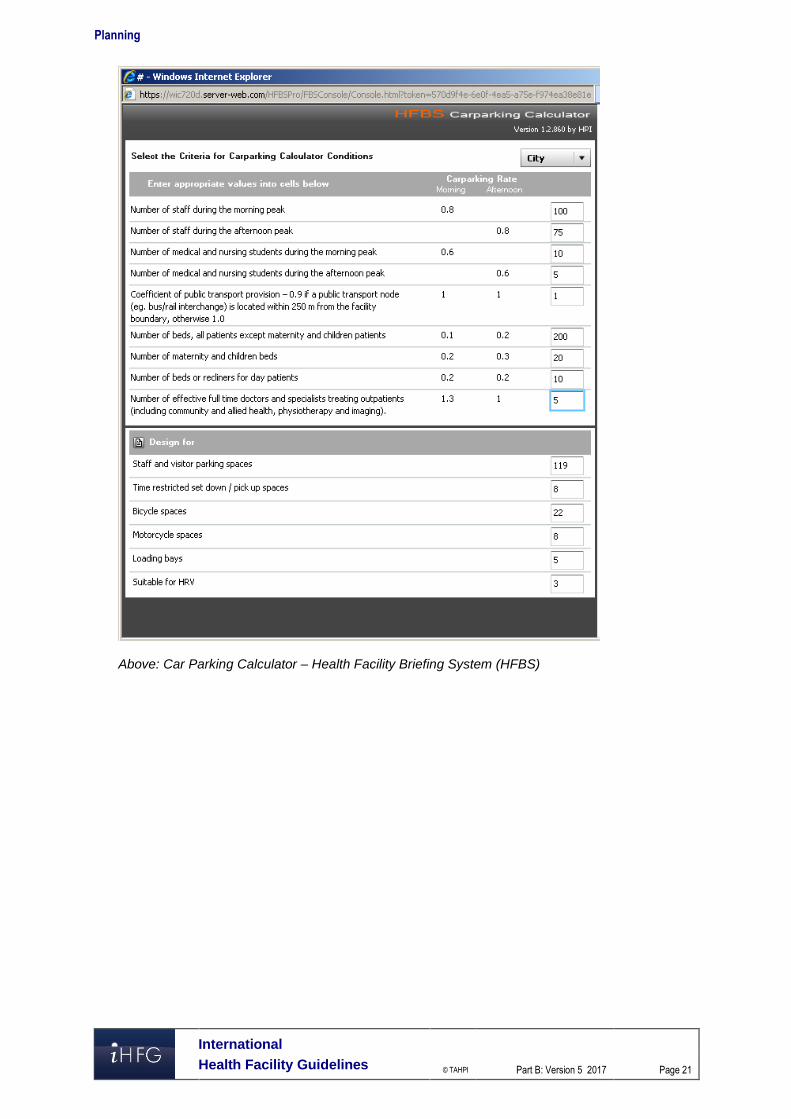
HFBS Carparking Calculator
Alternatively, the Health Facility Briefing System (HFBS) provides a tool that designers can rapidly and accurately estimate the number of parking required for cars, trucks and other vehicles. The tool is based on algorithms devised by transportation experts. Based on a set of 9 questions related to the numbers of staff and beds, the tool is able to accurately predict the estimated car parking load for the health facility. HFBS can be accessed on the website: www.healthdesign.com.au .
Planning
International
Health Facility Guidelines © TAHPI
Part B: Version 5 2017
Page 21
Above: Car Parking Calculator – Health Facility Briefing System (HFBS)
Planning
International
Health Facility Guidelines © TAHPI
Part B: Version 5 2017
Page 22
Carparking Design Parking bays may be organised in a variety of arrangements including 300, 450, 600 and 900 with single or two way aisles. The preferred parking angle is 900 which allows for the flexibility of two way aisles. Allow an area of 35 m2 for a typical carparking space; this allowance includes the aisle space required.
Carpark Bay Dimensions
Provide the following minimum car parking bay dimensions:
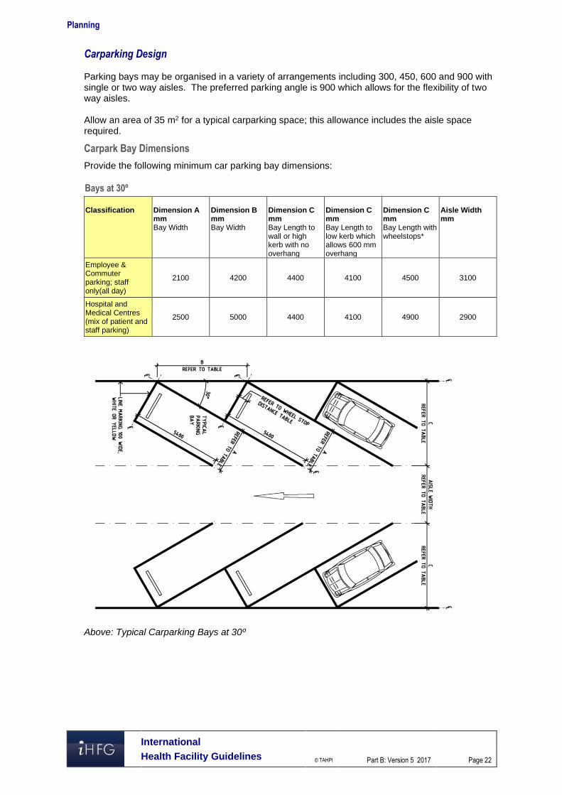
Bays at 30º
Classification
Dimension A mm Bay Width
Dimension B mm Bay Width
Dimension C mm Bay Length to wall or high kerb with no overhang
Dimension C mm Bay Length to low kerb which allows 600 mm overhang
Dimension C mm Bay Length with wheelstops*
Aisle Width mm
Employee & Commuter parking; staff only(all day)
2100 4200 4400 4100 4500 3100
Hospital and Medical Centres (mix of patient and staff parking)
2500 5000 4400 4100 4900 2900
Above: Typical Carparking Bays at 30º
Planning
International
Health Facility Guidelines © TAHPI
Part B: Version 5 2017
Page 23
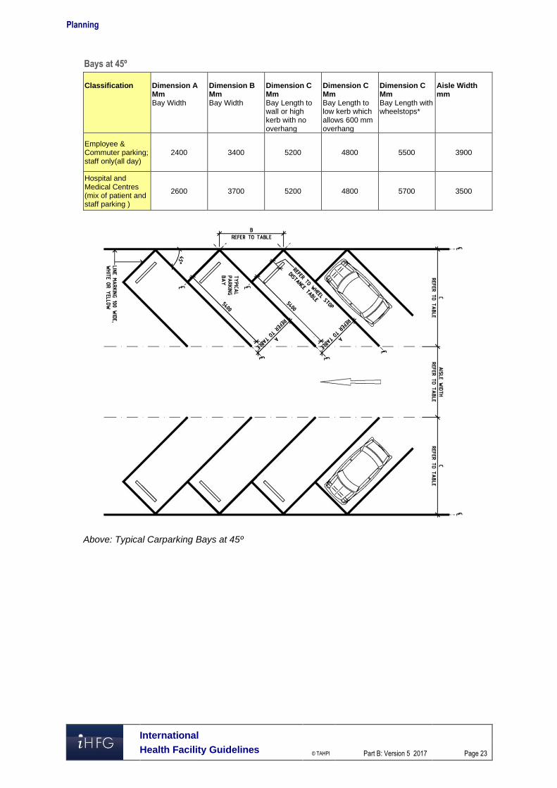
Bays at 45º
Classification
Dimension A Mm Bay Width
Dimension B Mm Bay Width
Dimension C Mm Bay Length to wall or high kerb with no overhang
Dimension C Mm Bay Length to low kerb which allows 600 mm overhang
Dimension C Mm Bay Length with wheelstops*
Aisle Width mm
Employee & Commuter parking; staff only(all day)
2400 3400 5200 4800 5500 3900
Hospital and Medical Centres (mix of patient and staff parking )
2600 3700 5200 4800 5700 3500
Above: Typical Carparking Bays at 45º
Planning
International
Health Facility Guidelines © TAHPI
Part B: Version 5 2017
Page 24
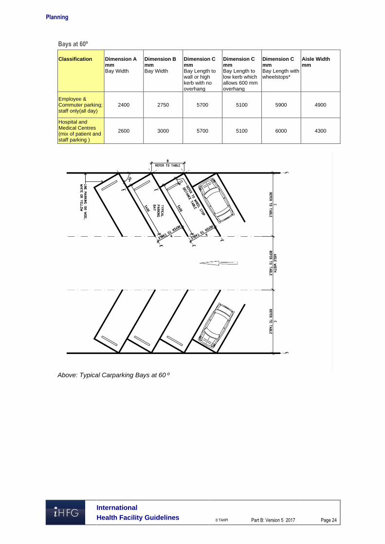
Bays at 60º
Classification
Dimension A mm Bay Width
Dimension B mm Bay Width
Dimension C mm Bay Length to wall or high kerb with no overhang
Dimension C mm Bay Length to low kerb which allows 600 mm overhang
Dimension C mm Bay Length with wheelstops*
Aisle Width mm
Employee & Commuter parking; staff only(all day)
2400 2750 5700 5100 5900 4900
Hospital and Medical Centres (mix of patient and staff parking )
2600 3000 5700 5100 6000 4300
Above: Typical Carparking Bays at 60 º
Planning
International
Health Facility Guidelines © TAHPI
Part B: Version 5 2017
Page 25
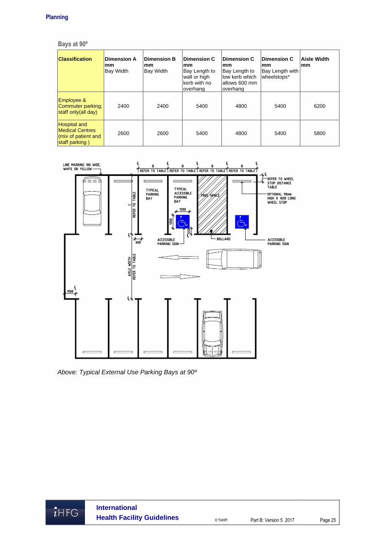
Bays at 90º
Classification
Dimension A mm Bay Width
Dimension B mm Bay Width
Dimension C mm Bay Length to wall or high kerb with no overhang
Dimension C mm Bay Length to low kerb which allows 600 mm overhang
Dimension C mm Bay Length with wheelstops*
Aisle Width mm
Employee & Commuter parking; staff only(all day)
2400 2400 5400 4800 5400 6200
Hospital and Medical Centres (mix of patient and staff parking )
2600 2600 5400 4800 5400 5800
Above: Typical External Use Parking Bays at 90º
Planning
International
Health Facility Guidelines © TAHPI
Part B: Version 5 2017
Page 26
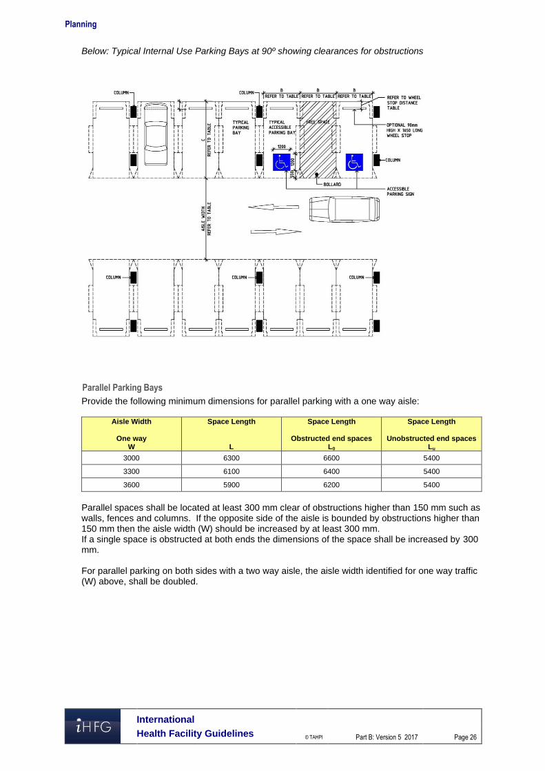
Below: Typical Internal Use Parking Bays at 90º showing clearances for obstructions
Parallel Parking Bays
Provide the following minimum dimensions for parallel parking with a one way aisle:
Aisle Width
One way W
Space Length
L
Space Length
Obstructed end spaces L0
Space Length
Unobstructed end spaces Lu
3000 6300 6600 5400
3300 6100 6400 5400
3600 5900 6200 5400
Parallel spaces shall be located at least 300 mm clear of obstructions higher than 150 mm such as walls, fences and columns. If the opposite side of the aisle is bounded by obstructions higher than 150 mm then the aisle width (W) should be increased by at least 300 mm. If a single space is obstructed at both ends the dimensions of the space shall be increased by 300 mm. For parallel parking on both sides with a two way aisle, the aisle width identified for one way traffic (W) above, shall be doubled.
Planning
International
Health Facility Guidelines © TAHPI
Part B: Version 5 2017
Page 27
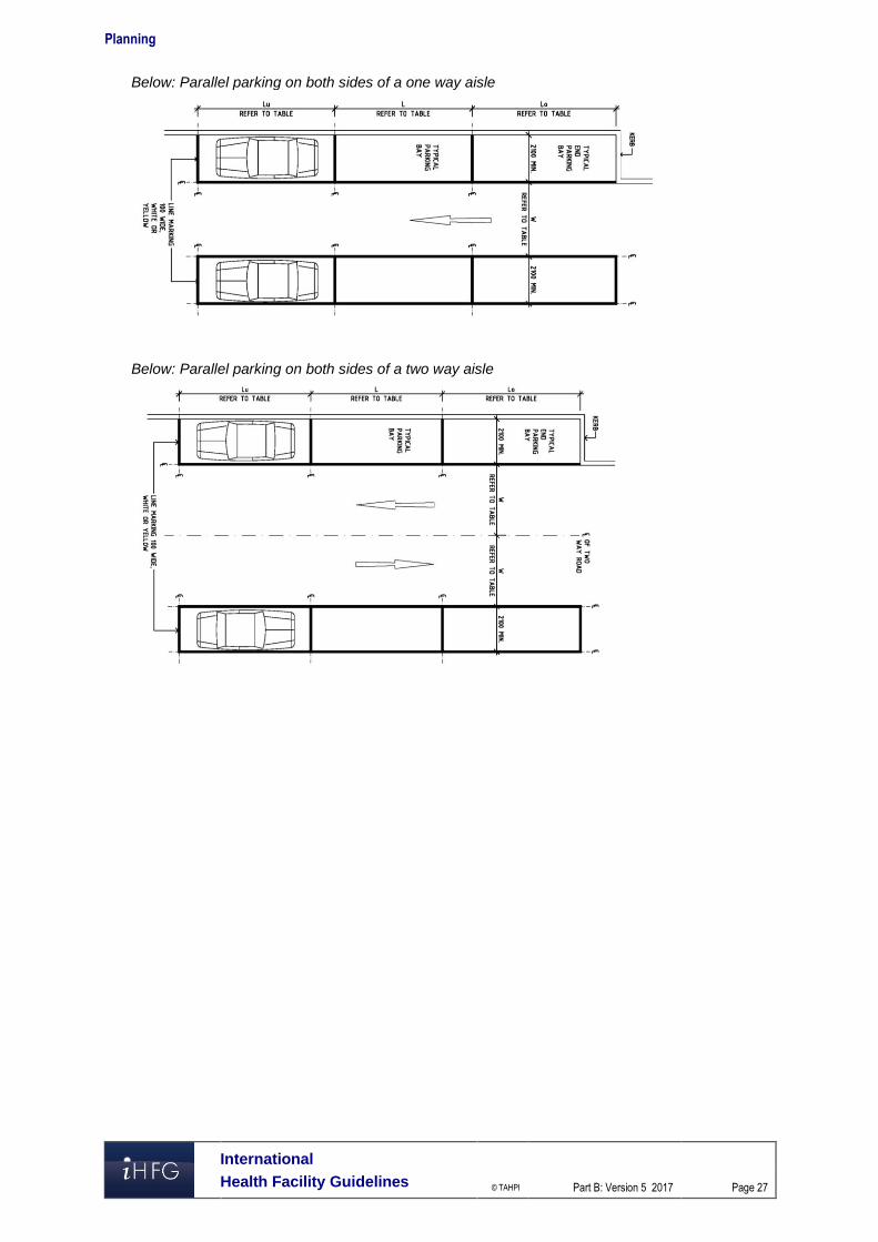
Below: Parallel parking on both sides of a one way aisle
Below: Parallel parking on both sides of a two way aisle
Planning
International
Health Facility Guidelines © TAHPI
Part B: Version 5 2017
Page 28
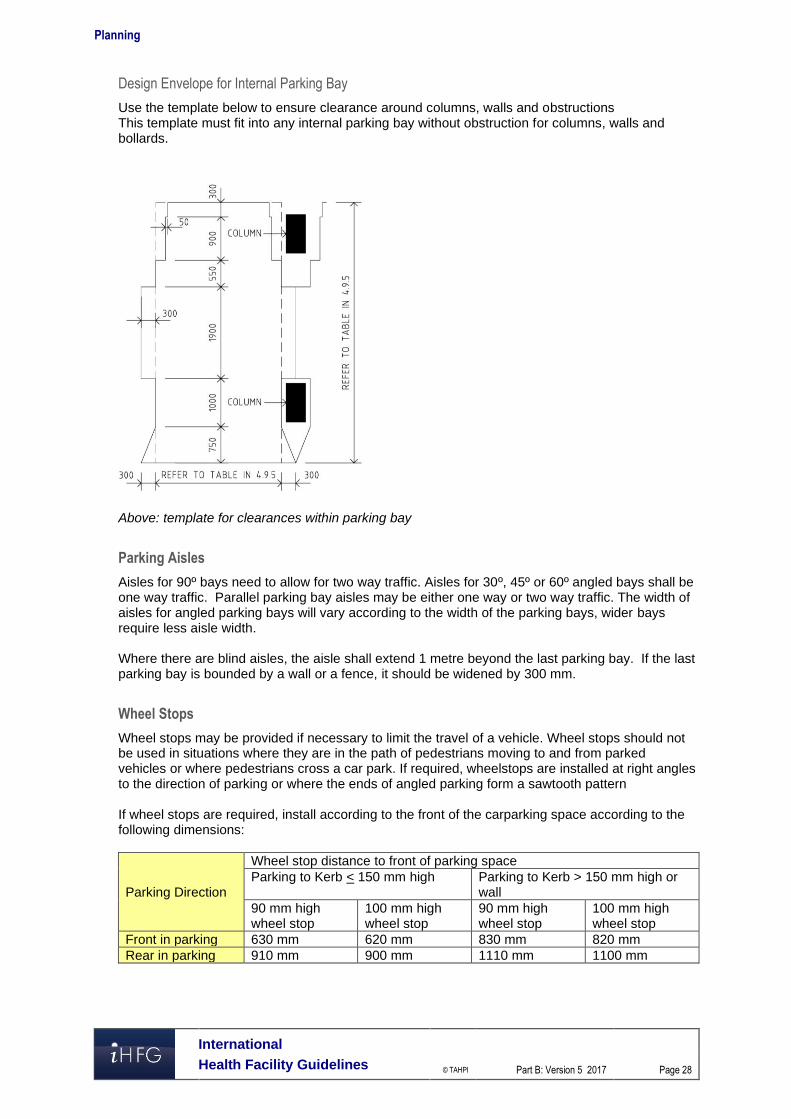
Design Envelope for Internal Parking Bay
Use the template below to ensure clearance around columns, walls and obstructions This template must fit into any internal parking bay without obstruction for columns, walls and bollards.
Above: template for clearances within parking bay
Parking Aisles
Aisles for 90º bays need to allow for two way traffic. Aisles for 30º, 45º or 60º angled bays shall be one way traffic. Parallel parking bay aisles may be either one way or two way traffic. The width of aisles for angled parking bays will vary according to the width of the parking bays, wider bays require less aisle width. Where there are blind aisles, the aisle shall extend 1 metre beyond the last parking bay. If the last parking bay is bounded by a wall or a fence, it should be widened by 300 mm.
Wheel Stops
Wheel stops may be provided if necessary to limit the travel of a vehicle. Wheel stops should not be used in situations where they are in the path of pedestrians moving to and from parked vehicles or where pedestrians cross a car park. If required, wheelstops are installed at right angles to the direction of parking or where the ends of angled parking form a sawtooth pattern If wheel stops are required, install according to the front of the carparking space according to the following dimensions:
Parking Direction
Wheel stop distance to front of parking space Parking to Kerb < 150 mm high Parking to Kerb > 150 mm high or
wall 90 mm high wheel stop
100 mm high wheel stop
90 mm high wheel stop
100 mm high wheel stop
Front in parking 630 mm 620 mm 830 mm 820 mm Rear in parking 910 mm 900 mm 1110 mm 1100 mm
Planning
International
Health Facility Guidelines © TAHPI
Part B: Version 5 2017
Page 29
Accessible Parking Bays
Accessible parking bays shall have the following minimum dimensions with a clearance height of 2500 mm from the entry/exit to the bay:
Description Width mm Length mm Angled Bays (45-900) 2600 5400 Parallel Bays 3200 7800
A shared area should be provided to the side of the accessible parking bay for loading and unloading; two accessible bays may be located either side of a single shared space.
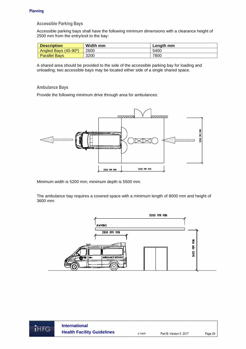
Ambulance Bays
Provide the following minimum drive through area for ambulances:
Minimum width is 5200 mm; minimum depth is 5500 mm. The ambulance bay requires a covered space with a minimum length of 8000 mm and height of 3600 mm:
Planning
International
Health Facility Guidelines © TAHPI
Part B: Version 5 2017
Page 30
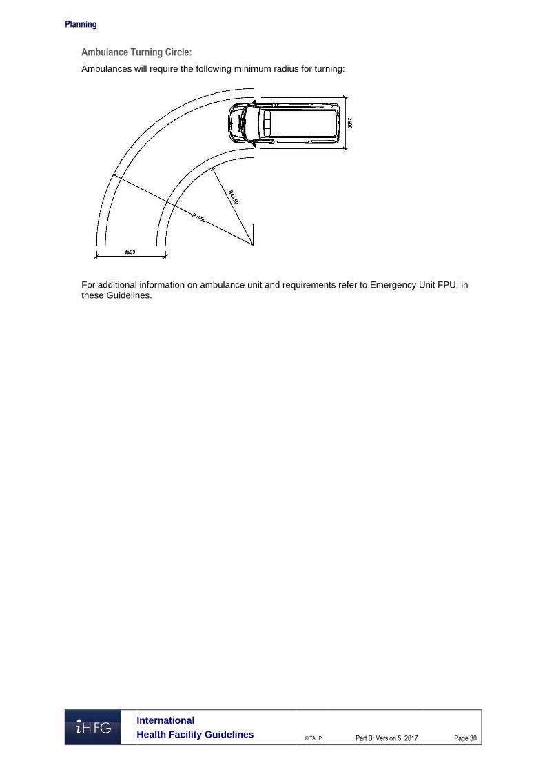
Ambulance Turning Circle:
Ambulances will require the following minimum radius for turning:
For additional information on ambulance unit and requirements refer to Emergency Unit FPU, in these Guidelines.