Ignition Coils Distributors Leads Associated Parts CV Aftermarket M08440T M

Ignition coils in motor vehicles
Function, diagnosis, troubleshooting.
Ideas today forthe cars of tomorrow
Lighting Electrics Electronics ThermalManagement
SalesSupport
Our Ideas,Your Success.
TechnicalService
2
Ignition coil structure
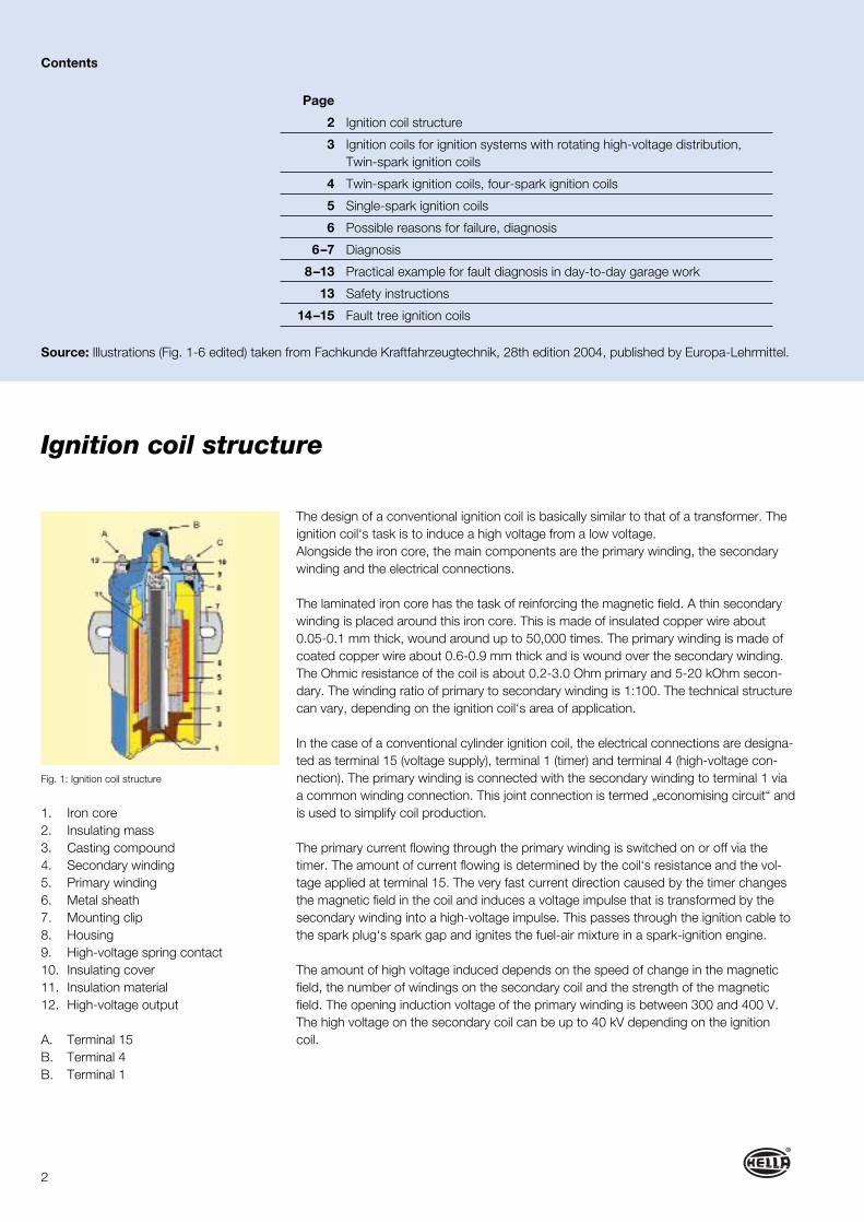
The design of a conventional ignition coil is basically similar to that of a transformer. The ignition coil‘s task is to induce a high voltage from a low voltage.Alongside the iron core, the main components are the primary winding, the secondary winding and the electrical connections.
The laminated iron core has the task of reinforcing the magnetic field. A thin secondary winding is placed around this iron core. This is made of insulated copper wire about 0.05-0.1 mm thick, wound around up to 50,000 times. The primary winding is made of coated copper wire about 0.6-0.9 mm thick and is wound over the secondary winding. The Ohmic resistance of the coil is about 0.2-3.0 Ohm primary and 5-20 kOhm secon-dary. The winding ratio of primary to secondary winding is 1:100. The technical structure can vary, depending on the ignition coil‘s area of application.
In the case of a conventional cylinder ignition coil, the electrical connections are designa-ted as terminal 15 (voltage supply), terminal 1 (timer) and terminal 4 (high-voltage con-nection). The primary winding is connected with the secondary winding to terminal 1 via a common winding connection. This joint connection is termed „economising circuit“ and is used to simplify coil production.
The primary current flowing through the primary winding is switched on or off via the timer. The amount of current flowing is determined by the coil‘s resistance and the vol-tage applied at terminal 15. The very fast current direction caused by the timer changes the magnetic field in the coil and induces a voltage impulse that is transformed by the secondary winding into a high-voltage impulse. This passes through the ignition cable to the spark plug‘s spark gap and ignites the fuel-air mixture in a spark-ignition engine.
The amount of high voltage induced depends on the speed of change in the magnetic field, the number of windings on the secondary coil and the strength of the magnetic field. The opening induction voltage of the primary winding is between 300 and 400 V. The high voltage on the secondary coil can be up to 40 kV depending on the ignition coil.
Contents
Page
2 Ignition coil structure
3 Ignition coils for ignition systems with rotating high-voltage distribution,Twin-spark ignition coils
4 Twin-spark ignition coils, four-spark ignition coils
5 Single-spark ignition coils
6 Possible reasons for failure, diagnosis
6–7 Diagnosis
8–13 Practical example for fault diagnosis in day-to-day garage work
13 Safety instructions
14–15 Fault tree ignition coils
1. Iron core2. Insulating mass3. Casting compound4. Secondary winding5. Primary winding6. Metal sheath7. Mounting clip8. Housing9. High-voltage spring contact10. Insulating cover11. Insulation material12. High-voltage output
A. Terminal 15B. Terminal 4B. Terminal 1
Source: Illustrations (Fig. 1-6 edited) taken from Fachkunde Kraftfahrzeugtechnik, 28th edition 2004, published by Europa-Lehrmittel.
Fig. 1: Ignition coil structure

3
15
14
These cylinder ignition coils are used in vehicles with ignition distributor in contact-controlled or transistor-controlled ignition systems. The three-pole electrical connection corresponds to that of a conventional ignition coil.
The primary circuit receives its voltage supply through terminal 15. The timer is con-nected to terminal 1 of the ignition coil and supplies the primary winding with ground. The high-voltage wire of the timer is connected to terminal 4. Whereas conventional ignition coils are still being used with older vehicles, ignition coils with integrated electro-nic control units are used today with vehicles equipped with transistor ignition.
Ignition coils for ignition systems with rotatinghigh-voltage distribution
Twin-spark coils are installed in ignition systems with static high-voltage distribution. These ignition coils are used with engines with an even number of cylinders.
The primary winding and secondary winding of the twin-spark coil each have two con-nections.
The primary winding is connected at terminal 15 with voltage supply (plus) and at ter-minal 1 (ground) with the output stage of the ignition timer or control unit. The secon-dary winding is connected to the spark plugs with the outputs (4 and 4a). With these systems, two spark plugs each are supplied with high voltage from one ignition coil. Since the ignition coil generates two sparks simultaneously, one spark plug has to be in the working cycle of the cylinder and the other offset by 360° in the ejection cycle.
In a four-cylinder engine, for example, cylinders 1 and 4 are connected to one ignition coil, and cylinders 2 and 3 to another. The ignition coils are triggered by the ignition out-put stages in the control unit. This receives the TDC signal from the crankshaft sensor in order to begin triggering the right ignition coil.
Twin-spark ignition coils
1. High-voltage connections2. Low-voltage connection3. Secondary winding4. Primary winding5. Iron core
Fig. 2: Twin-spark coil
Fig: Ignition coil
4
Four-spark ignition coils
1. Ignition control unit2. Ignition coil
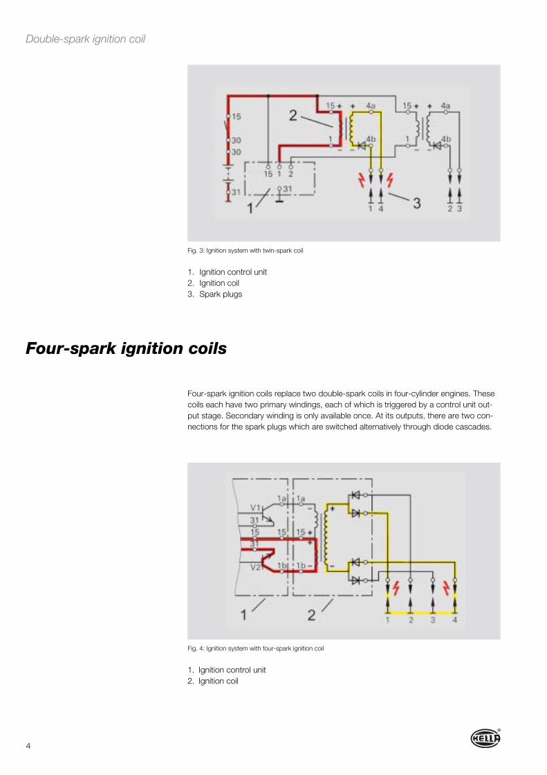
Four-spark ignition coils replace two double-spark coils in four-cylinder engines. These coils each have two primary windings, each of which is triggered by a control unit out-put stage. Secondary winding is only available once. At its outputs, there are two con-nections for the spark plugs which are switched alternatively through diode cascades.
1. Ignition control unit2. Ignition coil3. Spark plugs
Double-spark ignition coil
Fig. 3: Ignition system with twin-spark coil
Fig. 4: Ignition system with four-spark ignition coil

5
With systems with single-spark ignition coils, one ignition coil with primary and seconda-ry winding is assigned to each cylinder. These ignition coils are usually installed directly at the cylinder head above the spark plug.
These coils are also connected with the primary winding at terminal 15 (voltage supply plus) and at terminal 1 (ground) with the control unit. The secondary winding is con-nected with the output of terminal 4 to the spark plug. If a terminal 4b should be pre-sent, this connection is used to monitor misfiring. Triggering is in the sequence specified by the control unit.
A single-spark coil‘s circuit corresponds to that of a conventional ignition coil. In addi-tion, a high-voltage diode is used in the secondary circuit to suppress the so-called closing spark. The undesired spark produced when the primary winding is switched on through self-induction in the secondary winding is suppressed by this diode. This is possible since the secondary voltage of the closing spark has opposite polarity to the ignition spark. The diode blocks in this direction.
With single-spark coils the second output of the secondary winding is routed to ground through terminal 4b. A measuring resistor is installed in the ground cable to monitor ignition, this represents the drop in voltage caused by the ignition current during sparko-ver as a measured parameter for the control unit.
Single-spark ignition coils
1. Ignition control unit2. Spark plugs
1. Low-voltage connection2. Secondary winding3. High-voltage connection4. Spark plug5. Primary winding6. Iron core
Fig. 5: Single-spark coil
Fig. 6: Ignition system with single-spark coils

6
Internal short-circuitsOverheating of the coil caused by the ageing process, a faulty ignition module or a faulty output stage in the control unit.
Fault in the control voltageThe coil charging time increases on account of the voltage supply being too low, this can lead to premature wear or excess load on the ignition control unit or the output stages in the control unit.This can be caused by a faulty cable or weak battery.
Mechanical damageDamage to the ignition cables through marten bites.A faulty valve cover seal and escaping motor oil can damage the insulation of plug slot coils.Both causes lead to sparkover and thus to premature wear.
Contact faultContact resistance in the wiring due to humidity penetrating in the primary and secon-dary area, also frequently caused by engine washing or the use of grit in winter.
Faults can become noticeable as follows:� Engine does not start� Vehicle misfires� Poor acceleration or loss of power� Engine control unit switches to safe-home mode� Engine warning lamp lights up� Fault code is stored
Possible reasons for failure
Fig.: Contact fault
Fig.: Failure
There are different possibilities available for checking the ignition coil: testing the resistance values of the coils using the Ohmmeter.
Depending on the ignition system and ignition coil design, the following refe-rence values apply: (heed manufacturer‘s instructions)
Cylinder ignition coil (transistor ignition system)Primary: 0.5 Ω – 2.0 ΩSecondary: 8.0 kΩ – 19.0 kΩ
Diagnosis
Dismounted state
Fig.: Short-circuit

7
Cylinder ignition coil (electronic ignition system with map-controlled ignition) Primary: 0.5 Ω – 2.0 ΩSecondary: 8.0 kΩ – 19.0 kΩ
Single-spark or twin-spark coil (fully electronic ignition system) Primary: 0.3 Ω–1.0 ΩSecondary: 8.0 kΩ – 15.0 kΩ
The following tests can be used:� Test the ignition coil for mechanical damage.� Check the housing for hairline cracks or casting compound escaping.� Check electrical wiring and plug-type connections for damage or oxidation.� Check voltage supply to the ignition coil.� Read out the fault store using a diagnosis unit.� Engine control with ignition monitoring.� Representation of the high-voltage curve using an oscilloscope or ignition oscilloscope.
During all testing work on the system, it must not be forgotten that faults that are established during tests with the oscilloscope are not necessarily faults caused by the electronic system, they can also be caused by a mechanical problem in the engine. This can be the case, for example, if compression is too low with one cylinder, which means the oscilloscope shows the ignition voltage on this cylinder to be lower than that on the other cylinders.
Note:Although diagnosable engine management systems are installed in today‘s vehicles, the use of a multimeter or oscilloscope is necessary when checking ignition systems. In order to interpret the measuring results or images shown correctly, additional employee training is usually required. One important pre-requisite for successful diagnosis is a careful visual inspection at the beginning of the troubleshooting process.
Practical tip Note: Should a high-voltage diode be built into an ignition coil to suppress sparks,
resistance measurement at the secondary coil is not possible. In this case, the following method is helpful:
Connect a voltmeter in series between the secondary winding of the ignition coil and a battery. If the battery is connected in the diode‘s conducting direction, the voltmeter must display a voltage. After reversing the polarity of the connections in the blocking direction of the diode, no voltage may be displayed. If no voltage is indicated in either direction, an interruption in the secondary circuit must be assu-med. If a voltage is indicated in both directions, the high-voltage diode is faulty.
Installed state
Dismounted state

8
We would like to demonstrate the diagnosis of a twin-spark coil using the following example „combustion miss“. Vehicle: Alfa Romeo 147 1.6 TS with twin-spark ignition. Each cylinder has a main plug and a secondary plug. The ignition coils are triggered by the ignition output stages integrated in the engine control unit.
Practical example for fault diagnosis in day-to-day garage work
1. Using the diagnosis unitConnect the diagnosis unit to the 16-pole OBD plug. Depending on the vehi-cle manufacturer and date of registration, a different diagnosis socket and additional adapter may have to be used.
Customer complaint
� The customer reports a functional problem with the engine control system� Warning information on the instrument cluster
Fault: Engine monitoring system
Engine mechanics, battery, starting system and fuel system OK.
Troubleshooting
Diagnosis condition
Practical tip Before you start diagnosis you should heed the following:
• To be able to assign the vehicle correctly, it is important that the vehicle docu-ments (registration documents) are included with the job sheet.• Check the battery voltage. A poor voltage supply can lead to system failure, faulty measurements or drops in voltage.Check the system-related fuses. A quick look in the fuse box might eliminate the first possible fault source.

9
Carry out the following applications at the diagnosis unit:� Select program� Select vehicle� Select type of fuel� Select model� Select vehicle type
� Select required function� Select systemDepending which diagnosis unit is used, additional safety instructions can be dis-played here.� Start fault diagnosisTo build up communication with the control unit, sufficient battery voltage is required as well as the correct connection plug. Insufficient voltage supply to the control unit could be an indication of a wiring fault or a fault in the vehicle battery.
2. Read out the fault storeIn this case, fault PO303 was stored.� Combustion cylinder 3� Combustion miss detected on cylinder 3
3. Evaluate the detailsHere, additional information about a possible reason for the fault is stored� Ignition faulty� Injection valve faulty� Control unit faulty
Note:If several fault codes are displayed, delete the fault first. Then carry out a test drive with the diagnosis unit connected. Observe the parameters and read out the fault store.

10
4. Determining the reason for the faultPreparations for engine diagnosis� Prepare any additional diagnosis units that may be necessary such as multime-
ter or oscilloscope� Look for the technical documentsRemove the engine cover (if necessary)
5. Carry out a visual inspectionBefore you start with the actual diagnosis, you should check the engine harness and plug-type connectors for damage, as far as they can be seen. Bends in cables, lack of strain relief or a so-called „marten bite“ on the harness could be a possible reason for failure.
6. Check voltage supply on the cylinder 3 ignition coil� Remove the connection plug from the ignition coil� Measure the voltage at the two-pole plug on the harness side� Connect the red cable from the multimeter to PIN 2 (+), the black cable to
engine ground (-). Switch the ignition on. A voltage of more than 10.5 Volts should be measured. Measured value shown: 11.84 V. Measurement OK.
Practical tip
To check the voltage supply under load, we recommend repeating the mea-surement while actuating the starter. In order to prevent unnecessary fuel injec-tion you must remove all the injection valve connectors first.

11
7. Check primary triggering of cylinder 3 ignition coil� Remove the plug from the ignition coil� Connect the oscilloscope. Connect the probe tips to PIN 1 and PIN 2 using
the two-pole connection plug� Remove the plug connections at the injection valves� Start the engine
A signal should be clearly recognisable on the oscilloscope. In this example the measurement is successful.
8. Remove the ignition coil for further testing� Remove the plug from the ignition coil� Remove the high-voltage cable for the second spark plug� Remove the fastening screws� Pull the ignition coil off vertically and parallel to the plug slot
To avoid damage to the spark-plug connector, do not turn the ignition coil in any way.
Practical tip
Check plug slot for soiling caused by oil and water penetration. Remove and check the spark plugs.

12
9. Carrying out resistance measurementUse the multimeter to check the removed ignition coil. Connect an ohmmeter directly to the component plug PIN 1 and PIN 2 to measure the primary win-ding.� Reference value: 0.3 Ω - 1.0 Ω� Actual value: 0.5 Ω (OK)
To measure the secondary coil, measure the test probes directly at the high-voltage outputs of the ignition coil.� Reference value: 8.0 kΩ –15.0 kΩ� Actual value: ∞ (interruption secondary coil)
Always consult the manufacturer‘s specifications in this context.
10. Replacing the ignition coilHere, care must be taken that the spark-plug connector and the high-voltage cable for the second plug fit properly. Attach the ignition coil with the faste-ning screws. Then insert all the plug-type connections of the ignition coil and the injection valve plugs.
Practical tip The ignition coils in this vehicle are identical and can be swapped for testing.

13
Safety instructions
11. Deleting the fault storeDuring the diagnosis work, additional faults are detected by the control unit and have to be deleted before the test drive.
12. Carrying out a functional checkCarry out a test drive with the diagnosis unit connected. Then read out the fault store again.
During work on electronic ignition systems, contact with live components can result in potentially fatal injuries.This is not only valid for the high-voltage live secondary circuit, but also for the primary circuit. For this reason, testing and repair work should only be carried out by trained specialist staff.
Please heed the following safety measures:� Do not touch or remove the ignition cable, distributor cap and spark-plug
connector with the engine running.� Only connect or disconnect control units, plug-type connections and con-
nection cables with the ignition switched off.� Only carry out engine washing with the engine at a standstill and the igniti-
on switched off.� During all tests on the ignition system which require the engine to turn over
at starter speed, the voltage supply to the injection valves should be inter-rupted in order to protect the catalytic converter.
Note: Please always try to take the manufacturer‘s specifications into account
during all testing and diagnosis work. Depending on the manufacturer, additional vehicle-specific testing methods may have to be taken into consideration.

yes
Check wiring for loose plug-type connections,
breaks in cables, loose contactsand oxidation.
OK?
Pull ignition cable between ignition coil and ignition distribution out of the distributor
cap. Set up spark gap**** between cable andengine ground. Remove the plugs from the injection valves to prevent damage to the catalytic converter. Actuate the starter.
14
Fault tree for ignition coil with integratedignition control unit (ignition module)Example: VW/engine code APQ, Motronic MP 9.0.Diagnosis pre-requisite: Engine mechanics, battery, starting system and fuel system OK.
Is there an ignition spark?
no
yes
Remove 3-pole plugfrom the ignition module.
Check voltage supply betweenterminal 1 (-) and terminal 3 (+).
Ignition ON:Reference value: > 10.5 V
Actuate the starter:Reference value > 9.0 V
OK?
yes
no
yes
Check triggering signal* between plug terminal 2and control unit** terminal 24.
Actuate the starter,Reference value: rectangular signal
> 3.5 VOK?
Continue with
BContinue with
AContinue with
DContinue with
C
Replace ignition module
Check cables betweenplug terminal 1 and vehicle ground,plug terminal 2 and control unit** terminal 24 and plug terminal 3 and voltage supply (ignition terminal 15).
Eliminate interruptions.Repair or replace faults
parts.
no
yes
no
Check the Hall sensorin the ignition distributor
Remove 3-pole plug.Check voltage supply
between terminal 1 (-) and terminal 3 (+).Ignition ON:
Reference value > 10 VOK?
no
Starter turns overengine does not
start up START

* Use an oscilloscope** Motronic control unit*** Heed the vehicle manufacturer‘s repair instructions.**** To protect the output stage of the control unit, we recommend using a > 3 kOhm
resistor between the ignition coil and spark gap.
15
A
Functional checkIf necessary, delete fault store entries in the Motronic control unit.
B D
Check triggering signal* between plug terminal 2and control unit** terminal 13.
Plug connected, actuate the starter.Reference value: rectangular signal
> 3.5 VOK?
Check secondary circuit.Check ignition cable, distributor cap,distributor rotor, spark-plug connec-
tor and spark plugs,replace faulty parts if necessary.
If no faults can be found with the electric
connection of the Hall sensor,the Hall sensor must be
replaced.
Replace Motronic control unit ***
Check cables betweenHall sensor terminal 1 and control unit** terminal 17Hall sensor terminal 2 and control unit** terminal 13Hall sensor terminal 3 and control unit** terminal 8and eliminate any cable interruptions if appropriate.
yes
no
END
C

17 Ideas today forthe cars of tomorrow
© H
ella
KG
aA H
ueck
& C
o.,
Lip
pst
adt
9Z
2 99
9.12
7-96
7 T
T/07
.09/
0.4
P
rinte
d in
Ger
man
y
Hella KGaA Hueck & Co.Rixbecker Straße 7559552 Lippstadt, Germany
Phone: +49 (0) 29 41-38-0Fax: +49 (0) 29 41-38-7133Internet: www.hella.com


![IGNITION COILS · IGNITION COILS [ SyStem applIcatIonS] Distributor Based System for Gasoline Engines Gasoline Engine with a Distributorless Engine Management System CNG System with](https://static.fdocuments.in/doc/165x107/5e97dd5fb01115017d572ed1/ignition-coils-ignition-coils-system-applications-distributor-based-system-for.jpg)