igH - toyokokagaku.co.jp · Series KT 10– Welded* single stage HigH Pressure regulator HigH...
8
SERIES KT 10 SINGLE STAGE HIGH PRESSURE REGULATOR HIGH RELIABILITY AND SAFETY BY DESIGN u 10,000 psig inlet (690 bar) 5 to 10,000 psig outlet (0.35 to 690 bar) u Stainless steel or brass construction u Self relieving and non-relieving versions* u Machined from bar stock u Field repairable u Fine adjustment control u Piston sensing elementti u Low flow, 0.06 C v (HF option, 0.12 C v ) u Pneumatic actuator option for pneumatic outlet pressure control u Installation and operating instructions available at www.aptech-online.com in the Tech Briefs section ENGINEERING DATA Operating Parameters Source pressure** SS body 10,000 psig (690 bar) Brass body 6,000 psig (414 bar) Polyimide seat 10,000 psig (690 bar) PEEK seat 6,000 psig (414 bar) HF option 6,000 psig (414 bar) Delivery pressure*** 5 to 500 psig (0.34 to 34 bar) 5 to 800 psig (0.34 to 55 bar) 10 to 1,500 psig (0.7 to 103 bar) 15 to 2,500 psig (1 to 172 bar) 25 to 4,000 psig (1.7 to 276 bar) 50 to 6,000 psig (3.5 to 414 bar) 100 to 10,000 psig (7 to 690 bar) Design proof pressure 150% of maximum rating Design burst pressure 400% of maximum rating Other Parameters Inlet /outlet ports 1/4” NPT (options available) Flow coefficient Cv 0.06 (opt HF 0.12) Operating temperature -40 to +160F (-40 to +71C) Leak rate Bubble tight Self relieving* Standard, non-relieving optional (must be specified) Shipping weight (approx.) 5 lbs MATERIALS OF CONSTRUCTION KT 10S KT 10C KT 10B Body SS, 316 SS, 300 series Brass Inlet filter SS, 316 SS, 316 Bronze Piston and trim SS, 300 series SS, 300 series SS, 300 series Seat, main valve Polyimide (option available) Polyimide (option available) Polyimide (option available) Seat, vent valve PCTFE PCTFE PCTFE O-rings Fluoroelastomer / FKM (optional) Fluoroelastomer / FKM (optional) Fluoroelastomer / FKM (optional) Rings, back up PTFE PTFE PTFE All specifications subject to change without notice. D NCED A VA ESSURE TECHNOLOGY PR 687 T ECHNOLOGY WAY N APA CA 94558 u P H 707-259-0102 u F AX 707-259-0117 u www.aptech–online.com *Self relieving model vents pressure above set point automatically for ease of pressure adjustment and for added safety. Non-relieving model does not vent. **Specific device rating is the lowest of the ratings of body, seat and option selected. ***Device delivery pressure cannot exceed its source pressure rating.
Transcript of igH - toyokokagaku.co.jp · Series KT 10– Welded* single stage HigH Pressure regulator HigH...

Series KT 10single stage HigH Pressure regulatorHigH reliability and safety by design
u 10,000 psig inlet (690 bar) 5 to 10,000 psig outlet (0.35 to 690 bar)
u Stainless steel or brass construction
u Self relieving and non-relieving versions*
u Machined from bar stock
u Field repairable
u Fine adjustment control
u Piston sensing elementti
u Low flow, 0.06 Cv (HF option, 0.12 Cv)
u Pneumatic actuator option for pneumatic outlet pressure control
uInstallation and operating instructions available at www.aptech-online.com in the Tech Briefs section
engineering data
Operating ParametersSource pressure** SS body 10,000 psig (690 bar) Brass body 6,000 psig (414 bar) Polyimide seat 10,000 psig (690 bar) PEEK seat 6,000 psig (414 bar) HF option 6,000 psig (414 bar)Delivery pressure*** 5 to 500 psig (0.34 to 34 bar) 5 to 800 psig (0.34 to 55 bar) 10 to 1,500 psig (0.7 to 103 bar) 15 to 2,500 psig (1 to 172 bar) 25 to 4,000 psig (1.7 to 276 bar) 50 to 6,000 psig (3.5 to 414 bar) 100 to 10,000 psig (7 to 690 bar) Design proof pressure 150% of maximum rating Design burst pressure 400% of maximum rating
Other ParametersInlet /outlet ports 1/4” NPT (options available)Flow coefficient Cv 0.06 (opt HF 0.12)Operating temperature -40 to +160F (-40 to +71C)Leak rate Bubble tightSelf relieving* Standard, non-relieving optional (must be specified)Shipping weight (approx.) 5 lbs
Materials of construction KT 10S KT 10C KT 10B
Body SS, 316 SS, 300 series BrassInlet filter SS, 316 SS, 316 BronzePiston and trim SS, 300 series SS, 300 series SS, 300 seriesSeat, main valve Polyimide (option available) Polyimide (option available) Polyimide (option available)Seat, vent valve PCTFE PCTFE PCTFEO-rings Fluoroelastomer / FKM (optional) Fluoroelastomer / FKM (optional) Fluoroelastomer / FKM (optional)Rings, back up PTFE PTFE PTFE
All specifications subject to change without notice.
D NCEDA VA ESSURE TECHNOLOGY PR
687 Technology Way napa ca 94558 u ph 707-259-0102 u Fax 707-259-0117 uwww.aptech–onl ine.com
*Self relieving model vents pressure above set point automatically for ease of pressure adjustment and for added safety. Non-relieving model does not vent.
**Specific device rating is the lowest of the ratings of body, seat and option selected.
***Device delivery pressure cannot exceed its source pressure rating.

O R D E R I N G I N F O R M A T I O N KT 10 L 1 C 4P 4 60 20 PK Series Pressure Self-Relieving Body Ports Connection Gauge (Source/Delivery) Options
Non-Relieving Material
s e r i e s K t 1 0 — Q u a l i t y , r e l i a b i l i t y & P e r f o r M a n c e !
Panel Installations
Panel mount cut out dimension
HF = High flow PK = PEEK main valve seat UE = Polyurethane O-rings
BN = Buna-N O-rings EP = Ethylene
propylene O-rings P = Panel installation**
0 = No gauge 6 = 600 psig/bar 10 = 1,000 psig/bar 20 = 2,000 psig/bar
40 = 4,000 psig/bar 60 = 6,000 psig/bar Q = 10,000 psig/bar
B = Brass (4P porting only) C = Stainless steel (SS), 300 series S = Stainless steel (SS) 316
1 = Self relieving (venting) 0 = Non-relieving (non-venting) 2 = Pneumatic actuator (non-venting)*
KT 10F = 5-500 psig (0.34 to 34 bar) KT 10H = 5-800 psig (0.34 to 55 bar) KT 10J = 10-1,500 psig (0.7 to 103 bar) KT 10L = 15-2,500 psig (1 to 172 bar) KT 10N = 25-4,000 psig (1.7 to 276 bar) KT 10P = 50-6,000 psig (3.5 to 414 bar) KT 10R = 100-10,000 psig (7 to 690 bar) SS only
4P = 4 ports 4 = 1/4 inch NPT MS33649 porting available
HMI14371/May2014
4P
Range
Porting
All dimensions in inches. Metric dimensions (mm) are for reference only.
Pneumatic Actuator Note: Please refer to installation and operating instructions for dimensional and operating information related to this option.
CAUTION: Product selection is the sole responsibility of the user, regardless of any recommendations or suggestions made by the factory. The user shall make selections based upon their own analysis and testing with regard to function, material compatibility and product ratings. Proper installation, operation and maintenance are also required to assure safe, trouble free performance.
TOP VIEW
*Pneumatic actuator is only available with H, J, N & R pressure ranges. **Panel mount not available with pneumatic actuator option.

Series KT 10 –Welded*single stage HigH Pressure regulatorHigH reliability and safety by design
u 4,500 psig inlet (310 bar) 5 to 4,000 psig outlet (0.35 to 280 bar)
u Stainless steel 316L construction, electropolished and passivated body
u Self relieving and non-relieving versions**
u Machined from bar stock
u Field repairable
u Fine adjustment control
u Piston sensing elementti
u Low flow, 0.06 Cv (HF option, 0.12 Cv)
u Optional seat and seal materials available
u Pneumatic actuator option for pneumatic outlet pressure control
uInstallation and operating instructions available at www.aptech-online.com in the Tech Briefs section
engineering data
Operating ParametersSource pressure 4,500 psig (310 bar)Delivery pressure 5 to 500 psig (0.35 to 35 bar) 5 to 800 psig (0.35 to 56 bar) 10 to 1,500 psig (0.7 to 95 bar) 15 to 2,500 psig (1 to 175 bar) 25 to 4,000 psig (1.7 to 280 bar) Design proof pressure 150% of maximum rating Design burst pressure 400% of maximum rating
Other ParametersInlet /outlet ports 1/4 inch face sealFlow coefficient Cv 0.06 (opt HF 0.12)Operating temperature -40 to +160F (-40 to +71C)Leak rate* Bubble tightSupply pressure effect Refer to Installation and Operating InstructionsSelf relieving** Standard, non-relieving optional (must be specified)Shipping weight (approx.) 5 lbs
Materials of construction KT 10S
Body SS, 316LInlet filter SS, 316Piston and trim SS, 300 seriesSeat, main valve Polyimide (option available)Seat, vent valve PCTFEO-rings Fluoroelastomer / FKM (option available)Rings, back up PTFE
All specifications subject to change without notice.
D NCEDA VA ESSURE TECHNOLOGY PR
687 Technology Way napa ca 94558 u ph 707-259-0102 u Fax 707-259-0117 uwww.aptech–online.com
**This series is not assembled in a Class 100 cleanroom nor is **it helium leak tested, though it is of welded construction.
**Self relieving model vents pressure above set point to **atmosphere automatically for ease of pressure adjustment **and for added safety. Non-relieving model does not vent.

s e r i e s K t 1 0 — s e r v i c e a n d s u P P o r t b e y o n d c o M P a r e
O R D E R I N G I N F O R M A T I O N KT 10 L 1 S 4PW FV4 FV4 40 20 PK Series Pressure Relieving Body Ports Connection Gauge Options
Non-Relieving Material Inlet Outlet (Source/Delivery)
HF = High flow PK = PEEK main valve seat UE = Polyurethane O-rings
BN = Buna-N/NBR O-rings EP = Ethylene
propylene O-rings
0 = No gauge 6 = 600 psig/bar 10 = 1,000 psig/bar 20 = 2,000 psig/bar
40 = 4,000 psig/bar
S = 316L stainless steel
KT 10F = 5-500 psig (0.35 to 35 bar) KT 10H = 5-800 psig (0.35 to 56 bar) KT 10J = 10-1,500 psig (0.7 to 95 bar) KT 10L = 15-2,500 psig (1 to 175 bar) KT 10N = 25-4,000 psig (1.7 to 280 bar)
4PW = 4 ports MV4 = 1/4 inch face seal male FV4 = 1/4 inch face seal female
*Standard gauge ports are MV4 (FV4 available)
HMI14511/November2014
4PW
Range
Porting
1 = Self relieving (venting) 0 = Non-relieving (non-venting) 2 = Pneumatic actuator (non-venting)*
*Pneumatic actuator is only available with H, J, & N pressure ranges.
CAUTION: Product selection is the sole responsibility of the user, regardless of any recommendations or suggestions made by the factory. The user shall make selections based upon their own analysis and testing with regard to function, material compatibility and product ratings. Proper installation, operation and maintenance are also required to assure safe, trouble free performance.
All dimensions in inches. Metric dimensions (mm) are for reference only.
Pneumatic Actuator Note: Please refer to installation and operating instructions for dimensional and operating information related to this option.
ConnectionA
inch mm
FV4, MV4 1.85 ±.02 47.0
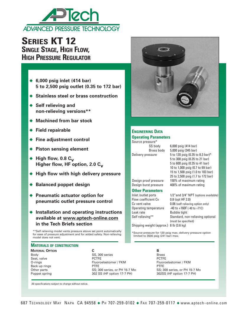
SERIES KT 12SINGLE STAGE, HIGH FLOW,HIGH PRESSURE REGULATOR
◆ 6,000 psig inlet (414 bar)5 to 2,500 psig outlet (0.35 to 172 bar)
◆ Stainless steel or brass construction
◆ Self relieving andnon-relieving versions**
◆ Machined from bar stock
◆ Field repairable
◆ Fine adjustment control
◆ Piston sensing elementti
◆ High flow, 0.8 CvHigher flow, HF option, 2.0 Cv
◆ High flow with high delivery pressure
◆ Balanced poppet design
◆ Pneumatic actuator option forpneumatic outlet pressure control
◆ Installation and operating instructionsavailable at www.aptech-online.comin the Tech Briefs section
ENGINEERING DATA
Operating ParametersSource pressure*
SS body 6,000 psig (414 bar)Brass body 5,000 psig (345 bar)
Delivery pressure 5 to 120 psig (0.35 to 8.3 bar)*5 to 300 psig (0.35 to 21 bar)5 to 600 psig (0.35 to 41 bar)10 to 1,000 psig (0.7 to 69 bar)15 to 1,500 psig (1.0 to 103 bar)25 to 2,500 psig (1.7 to 172 bar)
Design proof pressure 150% of maximum ratingDesign burst pressure 400% of maximum rating
Other ParametersInlet /outlet ports 1/2”and 3/4” NPT (options available)Flow coefficient Cv 0.8 (opt HF 2.0)Cv vent valve 0.06 (self relieving option only)Operating temperature -40 to +160F (-40 to +71C)Leak rate Bubble tightSelf relieving** Standard, non-relieving optional
(must be specified)Shipping weight (approx.) 8 lb (3.6 kg)
MATERIALS OF CONSTRUCTIONMATERIAL OPTION C BBody SS, 300 series BrassSeat, valve PCTFE PCTFEO-rings Fluoroelastomer / FKM Fluoroelastomer / FKMBack up rings PTFE PTFEOther parts SS; 300 series, or PH 15-7 Mo SS; 300 series, or PH 15-7 MoPoppet spring 302 SS (HF option 17-7 PH) 302SS (HF option 17-7 PH)
All specifications subject to change without notice.
687 TE C H N O L O G Y WAY NA PA CA 94558 ◆ PH 707-259-0102 ◆ FA X 707-259-0117 ◆ www.aptech–onl ine.com
**Self relieving model vents pressure above set point automaticallyfor ease of pressure adjustment and for added safety. Non-relievingmodel does not vent.
*Source pressure for 120 psig max. delivery pressure optionlimited to 3500 psig (241 bar) max.

2P 4P
S E R I E S K T 1 2 — Q U A L I T Y , R E L I A B I L I T Y & P E R F O R M A N C E !
Porting
O R D E R I N G I N F O R M A T I O NKT 12 J 1 C 4P 8 60 20 PSeries Pressure Relieving Material Ports Connection Gauge Options
Non-Relieving (Inlet/Outlet) Source DeliveryHF = High flow
P = Panel installation**
Note: HF option notrecommended for H2 service.
0 = No gauge4 = 400 psig/bar6 = 600 psig/bar
10 = 1,000 psig/bar20 = 2,000 psig/bar40 = 4,000 psig/bar60 = 6,000 psig/bar
Gauge ports are1/4 inch female NPT.
B = BrassC = Stainless steel (SS), 300 series
1 = Self relieving (venting)0 = Non-relieving (non-venting)2 = Pneumatic actuator (non-venting)*
KT 12B = 5-120 psig (0.35 to 8.3 bar)KT 12E = 5-300 psig (0.35 to 21 bar)KT 12G = 5-600 psig (0.35 to 41 bar)KT 12I = 10-1,000 psig (0.7 to 69 bar)
KT 12J = 15-1,500 psig (1.0 to 103 bar)KT 12L = 25-2,500 psig (1.7 to 172 bar)
2P = 2 ports4P = 4 ports
4PQ = 4 ports
8 = 1/2 inch NPT12 = 3/4 inch NPT
HMI13190/March2013
Range
Panel Installations
Panel mount cut out dimension4PQ
CAUTION: Product selection is the sole responsibility of the user,regardless of any recommendations or suggestions made by the factory.The user shall make selections based upon their own analysis andtesting with regard to function, material compatibility and productratings. Proper installation, operation and maintenance are alsorequired to assure safe, trouble free performance.
Pneumatic Actuator Note: Please refer toinstallation and operating instructions fordimensional and operating information relatedto this option.
*Pneumatic actuator is only available with G, J and L pressure ratings. **Panel mount not available with pneumatic actuator option.
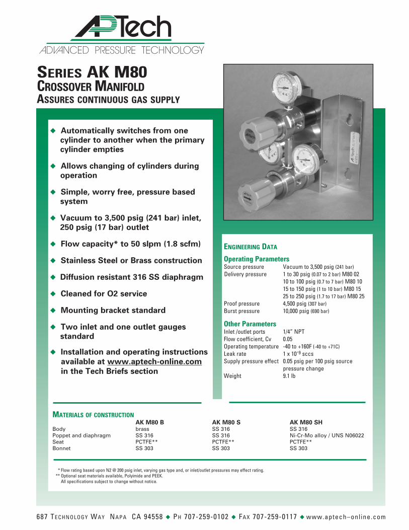
Series AK M80Crossover Manifoldassures Continuous gas supply
u Automatically switches from one cylinder to another when the primary cylinder empties
u Allows changing of cylinders during operation
u Simple, worry free, pressure based system
u Vacuum to 3,500 psig (241 bar) inlet, 250 psig (17 bar) outlet
u Flow capacity* to 50 slpm (1.8 scfm)
u Stainless Steel or Brass construction
u Diffusion resistant 316 SS diaphragm
u Cleaned for O2 service
u Mounting bracket standard
u Two inlet and one outlet gauges standard
u Installation and operating instructions available at www.aptech-online.com in the Tech Briefs section
engineering data
Operating ParametersSource pressure Vacuum to 3,500 psig (241 bar) Delivery pressure 1 to 30 psig (0.07 to 2 bar) M80 02 10 to 100 psig (0.7 to 7 bar) M80 10 15 to 150 psig (1 to 10 bar) M80 15 25 to 250 psig (1.7 to 17 bar) M80 25Proof pressure 4,500 psig (307 bar)Burst pressure 10,000 psig (690 bar)
Other ParametersInlet /outlet ports 1/4” NPTFlow coefficient, Cv 0.05Operating temperature -40 to +160F (-40 to +71C)Leak rate 1 x 10⁻⁹ sccsSupply pressure effect 0.05 psig per 100 psig source pressure changeWeight 9.1 lb
Materials of ConstruCtion AK M80 B AK M80 S AK M80 SH
Body brass SS 316 SS 316Poppet and diaphragm SS 316 SS 316 Ni-Cr-Mo alloy / UNS N06022Seat PCTFE** PCTFE** PCTFE**Bonnet SS 303 SS 303 SS 303
* Flow rating based upon N2 @ 200 psig inlet, varying gas type and, or inlet/outlet pressures may effect rating. ** Optional seat materials available, Polyimide and PEEK. All specifications subject to change without notice.
D NCEDA VA ESSURE TECHNOLOGY PR
687 Technology Way napa ca 94558 u ph 707-259-0102 u Fax 707-259-0117 u www.aptech–onl ine.com
O R D E R I N G I N F O R M A T I O N Series AK M80 10 S 40 VS
Material Inlet Gauges Options
AK M80 02 = 1 - 30 psig (.07 to 2 bar) S = Stainless steel 316 (SS) 4 = 0-400 psig PK = PEEK seatAK M80 10 = 2 - 100 psig (.7 to 7 bar) SH = SS with Ni-Cr-Mo alloy 6 = 0-600 psig VS = Polyimide seatAK M80 15 = 15 - 150 psig (1 to 10 bar) internals 10 = 0-1,000 psig AK M80 25 = 25 - 250 psig (1.7 to 17 bar) B = Brass 20 = 0-2,000 psig
30 = 0-3,000 psig 40 = 0-4,000 psig
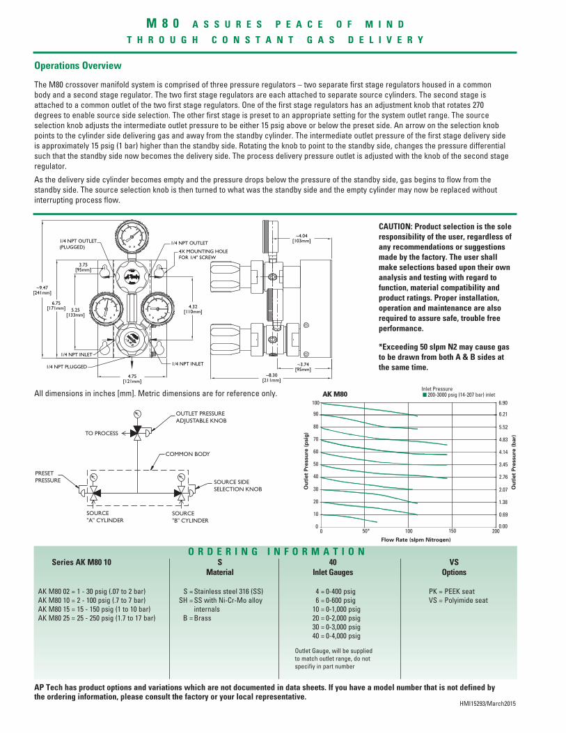
Operations Overview
M 8 0 a s s u r e s p e a C e o f M i n d
t h r o u g h C o n s t a n t g a s d e l i v e r y
HMI15293/March2015
The M80 crossover manifold system is comprised of three pressure regulators – two separate first stage regulators housed in a common body and a second stage regulator. The two first stage regulators are each attached to separate source cylinders. The second stage is attached to a common outlet of the two first stage regulators. One of the first stage regulators has an adjustment knob that rotates 270 degrees to enable source side selection. The other first stage is preset to an appropriate setting for the system outlet range. The source selection knob adjusts the intermediate outlet pressure to be either 15 psig above or below the preset side. An arrow on the selection knob points to the cylinder side delivering gas and away from the standby cylinder. The intermediate outlet pressure of the first stage delivery side is approximately 15 psig (1 bar) higher than the standby side. Rotating the knob to point to the standby side, changes the pressure differential such that the standby side now becomes the delivery side. The process delivery pressure outlet is adjusted with the knob of the second stage regulator.
As the delivery side cylinder becomes empty and the pressure drops below the pressure of the standby side, gas begins to flow from the standby side. The source selection knob is then turned to what was the standby side and the empty cylinder may now be replaced without interrupting process flow.
Outlet Gauge, will be supplied to match outlet range, do not specifiy in part number
All dimensions in inches [mm]. Metric dimensions are for reference only.
CAUTION: Product selection is the sole responsibility of the user, regardless of any recommendations or suggestions made by the factory. The user shall make selections based upon their own analysis and testing with regard to function, material compatibility and product ratings. Proper installation, operation and maintenance are also required to assure safe, trouble free performance.
*Exceeding 50 slpm N2 may cause gas to be drawn from both A & B sides at the same time.
AP Tech has product options and variations which are not documented in data sheets. If you have a model number that is not defined by the ordering information, please consult the factory or your local representative.


![Pressure switches and Thermostats, type KP€¦ · Type Range [psig] Differential [psi] Reset Pressure connection Max. operat-ing pressure [psig] Min. burst pressure [psig] Code nos](https://static.fdocuments.in/doc/165x107/5e286d5dcd347d7fa07fa52f/pressure-switches-and-thermostats-type-kp-type-range-psig-differential-psi.jpg)