
IFU 087.5 DeWaltTwin Slot Instructions A5 size · ifu 087.5 additional equipment required: •...
8
DEWALT 210 Bath Road Slough, Berks. SL1 3YD Tel: 01753 567055 Fax: 01759 572112 www.dewalt.co.uk Copyright DEWALT 01/06 DE6242
Transcript of IFU 087.5 DeWaltTwin Slot Instructions A5 size · ifu 087.5 additional equipment required: •...

DEWALT 210 Bath Road Slough, Berks. SL1 3YD
Tel: 01753 567055 Fax: 01759 572112 www.dewalt.co.uk
Copyright DEWALT 01/06
DE6242
IFU 087.5
ADDITIONAL EQUIPMENT REQUIRED:
• ELECTRIC HAND ROUTER
• 30mm ROUTER GUIDE BUSH
• TUNGSTEN CARBIDE ROUTER CUTTER - 12.7mm DIA X 50mm (1/2” DIA X 2”)
• MINIMUM OF 2 QUICK ACTION, ‘G’ CLAMPS OR SCREW CLAMPS
Page 2
FACE 1 Left & Right Hand
90° Joints
FACE 2 Left & Right Hand 45°
For 500, 600, 616, 650. 700, 720, 740, 900 & 920mm Wide
Worktops
Holder for flush fitting
location pegs
Rout recesses for Worktop Connecting Bolts
Carrying Handle
Edge of jig to cut indicator
Edge of jig to cut indicator
Denotes Female Denotes Male
Slot for screw clamp
Slot for screw clamp
DE6289
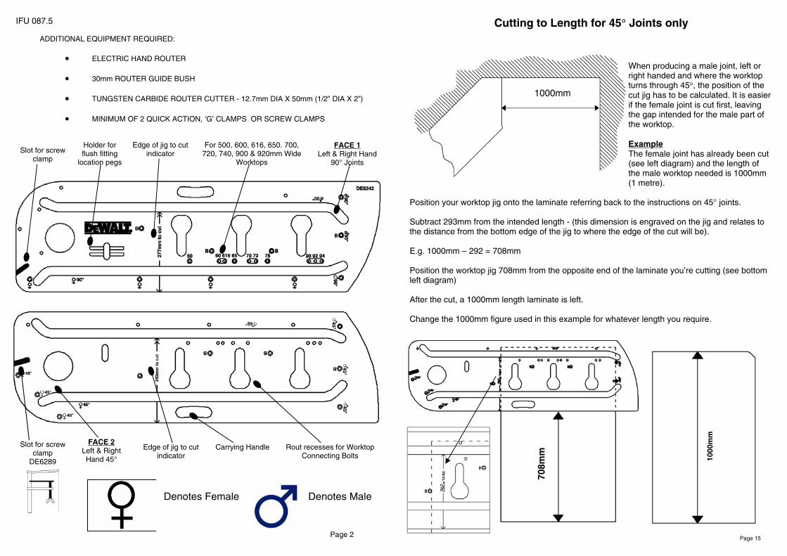
Cutting to Length for 45° Joints only
When producing a male joint, left or right handed and where the worktop turns through 45°, the position of the cut jig has to be calculated. It is easier if the female joint is cut first, leaving the gap intended for the male part of the worktop. Example The female joint has already been cut (see left diagram) and the length of the male worktop needed is 1000mm (1 metre).
Position your worktop jig onto the laminate referring back to the instructions on 45° joints. Subtract 293mm from the intended length - (this dimension is engraved on the jig and relates to the distance from the bottom edge of the jig to where the edge of the cut will be). E.g. 1000mm – 292 = 708mm Position the worktop jig 708mm from the opposite end of the laminate you’re cutting (see bottom left diagram) After the cut, a 1000mm length laminate is left. Change the 1000mm figure used in this example for whatever length you require.
1000
mm
708m
m
1000mm
Page 15

1. MALE JOINT Prepare the male worktop with the laminate face up.
2. Insert 2 pins in holes marked ♂ 45°. 3. Refer to the page on ‘cutting to length’ on
page 15 to find out where to mark the pencil line to determine the position of the jig along the length of the worktop.
4. Make sure the 2 pins in the holes marked
♂ 45°are firmly pushed against the post formed edge (see diagram X)
5. Clamp the jig to the worktop checking that both pins are still against the worktop. Make sure the clamps will not obstruct the router path.
6. Follow steps 6 to 10 for cutting the worktop. 7. CUTTING METHOD Position the
router in the far left side of the slot. Set the router to cut a depth of 10mm.
8. IMPORTANT - Position the router in the slot and cut from left to right, pulling the router against the edge of the slot closest to you.
9. Remove the router, and start again from the far left of the central slot, but increase the depth a further 10mm.
10. Follow steps 7 – 9, until cut is complete.
For the final finishing cut, position the router again in the far left side of the slot, and set the router to cut at the full depth of the worktop. Again, cut from left to right but apply the pressure to the edge furthest away from you
11. MALE BOLT RECESSES Prepare the male worktop with the laminate face down. 12. Insert 3 pins in the holes marked ’B’. 13. Make sure the 3 pins are firmly pushed against the front cut out and the edge of the worktop (see diagram Z). 14. Clamp the jig to the worktop checking that all 3 pins are still firmly against the worktop. Make sure the clamps will not obstruct the router path. 15. You will need a depth of 20mm for the worktop connectors. Do not exceed 10mm per cut. 16. Cut the bolt recesses out, each time clearing the waste material after each cut.
Right Hand 45° Male Joints
Page 14
DIAGRAM X MALE JOINT- LAMINATE FACE UP
DIAGRAM Y
DIAGRAM Z MALE JOINT- LAMINATE FACE DOWN
Protecting the Environment
Separate Collection This product must not be disposed of with normal household waste. Should you find one day that your DEWALT product needs replacement, or it is of no further use to you, do not dispose of it with household waste. Make this product available for separate collection.
Separate collection of used products and packaging allows material to be recycled and used again. Re-use of recycled materials helps prevent environmental pollution and reduces the demand for raw materials.
Local regulations may provide for separate collection of electrical products from the household, at municipal waste sites or by the retailer when you purchase a new product. DEWALT provides a facility for the collection and recycling of DEWALT products once they have reached the end of their working life. To take advantage of this service please return your product to any authorised repair agent who will collect them on our behalf.
You can check the location of your nearest authorised repair agent at the address indicated in this manual. Alternately, list of authorised DEWALT repair agents and full details of our after-sales service and contacts are available on the internet at: www.2helpU.com
Page 3

GUARANTEE
• ONE YEAR FULL WARRANTY •
If your DEWALT product becomes defective due to faulty materials or workmanship within 12 months of the date of purchase, we will guarantee to replace all defective parts free of charge or, at our discretion, replace the unit free of charge provided that:
• The products was not misused.
• Repairs have not been attempted by unauthorised persons.
• Proof of purchase date is produced. This guarantee is offered as an extra benefit and is additional to consumers statuary rights. For the locations of your nearest authorised DEWALT repair agent, please use the appropriate telephone number on the back of this manual. Alternatively, a list of authorised repair agents are available on the internet at www.2helpU.com
Page 4
1. FEMALE JOINT Refer to the diagrams on the different joints available.
2. Prepare the female worktop with the laminate face down and the post formed (curved edge) towards the left.
3. Insert 2 or 3 pins in the holes marked ♀ 45° (see diagram T)
4. Slide the jig along the length of the worktop so that when cut is made, the joint face is a little longer than the worktop width. Once the jointing face has been cut, there will be enough length for the male worktop to fit (minor adjustment may be necessary (see diagram P).
5. Make sure the 2 or 3 pins in the holes marked ♀ 45° are firmly pushed against the front post formed edge. 6. Clamp the jig to the worktop checking that both pins are still against the worktop. Make sure the clamps will not obstruct the router path. 7. Once the cut is complete, cut off the excess (Diagram V), so that the distance from point 1 to point 2 is equal to your worktop width. 8. CUTTING Position the router in the far left side of the central slot. Set the router to cut a depth of 10mm. 9. IMPORTANT - Position the router in the slot and
cut from left to right, pulling the router against the edge of the slot closest to you. 10. Remove the router, and start again from the far left of the central slot, but increase the depth a further 10mm. 11. Follow steps 8 – 10, until cut is complete. 12. For the final finishing cut, position the router again in the far left side of the central slot, and set the router to cut at the full depth of the worktop. Again, cut from left to right but apply the pressure to the edge furthest away from you.
13. FEMALE BOLT RECESSES Prepare the female worktop with the laminate face down.
14. Insert 3 pins in the holes marked ‘B’ (see diagram W).
15. Make sure the 3 pins are firmly pushed against the front cut out and the edge of the worktop.
16. Clamp the jig to the worktop checking that all 3 pins are still firmly against the worktop. Make sure the clamps will not obstruct the router path.
17. You will need a depth of 20mm for the worktop connectors. Do not exceed 10mm per cut.
18. Cut the bolt recesses out, each time clearing the waste material after each cut. .
DIAGRAM V FEMALE JOINT– TRIM WORKTOP
Cut off
Point 1 Point 2
Right Hand 45° Female Joints
DIAGRAM W FEMALE BOLT RECESS - LAMINATE FACE DOWN
Page 13
DIAGRAM T FEMALE JOINT- LAMINATE FACE DOWN
Worktop Width
DIAGRAM U

1. MALE JOINT Prepare the male worktop with the laminate face down.
2. Insert 2 pins in holes marked ♂ 45°. 3. Refer to the page on ‘cutting to length’ on page
15 to find out where to mark the pencil line to determine the position of the jig along the length of the worktop.
4. Make sure the 2 pins in the holes marked ♂ 45° are firmly pushed against the post formed edge (see diagram Q)
5. Clamp the jig to the worktop checking that both pins are still against the worktop. Make sure the clamps will not obstruct the router path.
6. Follow steps 6 to 10 for cutting the worktop. 7. CUTTING METHOD Position the router in the far left side of the slot. Set the router to cut a depth of 10mm. 8. IMPORTANT - Position the router in the slot and cut from left to right, pulling the router against the edge of the slot closest to you. 9. Remove the router, and start again from the far left of the central slot, but increase the depth a further 10mm. 10. Follow steps 7 – 9, until cut is complete. 11. For the final finishing cut, position the router again in the far left side of the slot, and set the router to cut at the full depth of the worktop. Again, cut from left to right but apply the pressure to the edge furthest away from you.
12. MALE BOLT RECESSES Pre-pare the male worktop with the laminate face down. 13. Insert 3 pins in the holes marked ’B’. 14. Make sure the 3 pins are firmly pushed against the front cut out and the edge of the worktop (see diagram S). 15. Clamp the jig to the worktop check-ing that all 3 pins are still firmly against the worktop. Make sure the clamps will not obstruct the router path. 16. You will need a depth of 20mm for the worktop connectors. Do not exceed 10mm per cut. 17. Cut the bolt recesses out, each time clearing the waste material after each cut.
Left Hand 45° Male Joints
Page 12
DIAGRAM Q MALE JOINT - LAMINATE FACE DOWN
DIAGRAM R
DIAGRAM S MALE BOLT RECESS - LAMINATE FACE DOWN
Safety Notes
This jig will enable you to cut …….
Before starting ……... • Never cut worktop to length until all joints are complete and have been checked for
correct fit. • Make sure the worktop is secured firmly to the bench or trestle. • Ensure that the jig is firmly secured to the worktop. • Ensure there are no obstructions in the path of the router e.g. clamps or bench. • Always use good quality sharp router bits • Always wear eye protection when cutting. • Always wear ear protection if cutting for long periods • Always cut from left to right. • Always cut into post formed edge to avoid breakout or chipping. • Always keep the router vertical to the jig and worktop. • Never exceed 10mm depth of cut in one pass. • Never remove the router from the jig or position the router whilst cutter is still rotating.
The cutter may cut into the jig and damage the bush location faces.
Page 5
CORNER JOINT - USING THE RIGHT HAND AND LEFT HAND 45° JOINTS
STANDARD LEFT & RIGHT HAND 90° JOINTS
45° JOINTS - RIGHT AND LEFT HAND
Female Male Male Female
Female
Female
Female
Female
Male
Male
Male

Page 6
1. FEMALE JOINT Refer to the diagrams on the different joints available.
2. Prepare the female worktop with the laminate or sealed prepared surface, face up and the post formed (curved edge) towards you.
3. For all 90° joints, the jig should be placed with the logo uppermost.
4. Insert 3 pins in the holes marked ♀.
5. Insert the 4th pin in the hole dependant on your worktop width. e.g. As in the example shown, if your worktop is 700mm wide then insert the 3rd pin in the hole marked 700 (see diagram A).
6. Make sure the 3 pins in the holes marked with ♀ are firmly pushed against the front post formed edge and the pin in the hole marked with the worktop width is pushed firmly against the edge of the worktop (see diagram A)
7. Clamp the jig to the worktop checking that all 3 pins have not moved away from the worktop. Make sure the
8. CUTTING METHOD Position the router in the far left side of the slot. Set the router to cut a depth of 10mm. 9. IMPORTANT - Position the router in the slot and cut from left to right, pulling the router against the edge
of the slot closest to you. 10. Remove the router, and start again from the far left of the central slot, but increase the depth a further 10mm. 11. Follow steps 8 – 9, until cut is complete.
13. FEMALE BOLT RECESSES Prepare the female worktop with the laminate or prepared surface face down.
14. Insert 3 pins in the holes which
are marked B. 15. Make sure the 3 pins are firmly
pushed against the front cut out and the edge of the worktop (see diagram C).
16. Clamp the jig to the worktop checking that all 3 pins are still firmly against the worktop. Make sure the clamps will not obstruct the router path.
17. You will need a depth of 20mm for the worktop connectors. Do not exceed 10mm per cut. 18. Cut the bolt recesses out, each time clearing the waste material after each cut.
90° Female Joints - Left Side
DIAGRAM A FEMALE JOINT - LAMINATE FACE UP
DIAGRAM C FEMALE BOLT RECESS - LAMINATE FACE DOWN.
DIAGRAM B
Using G-clamp
Using Screw clamp DE6289
1. FEMALE JOINT Refer to the diagrams on the different joints available. For 45° joints the jig should always be placed with the logo facing down.
2. Prepare the female worktop with the laminate face up and the post formed (curved edge) towards the left.
3. Insert 2 or 3 pins in the holes marked ♀ 45° (see diagram M)
4. Slide the jig along the length of the worktop so that when cut is made, the joint face is a little longer than the worktop width. Once the jointing face has been cut, there will be enough length for the male worktop to fit (minor adjustment may be necessary (see diagram O).
5. Make sure the 2 or 3 pins in the holes marked
♀ 45° are firmly pushed against the front post formed edge. 6. Clamp the jig to the worktop checking that both pins are still against the worktop. Make sure the clamps will not obstruct the router path. 7. Once the cut is complete, cut off the excess (Diagram O), so that the distance from point 1 to point 2 is equal to your worktop width. 8. CUTTING Position the router in the far left side of the central slot. Set the router to cut a depth of 10mm.
9. IMPORTANT - Position the router in the slot and cut from left to right, pulling the router against the edge of the slot closest to you.
10. Remove the router, and start again from the far left of the central slot, but increase the depth a further 10mm.
11. Follow steps 8 – 10, until cut is complete. 12. For the final finishing cut, position the router again in
the far left side of the central slot, and set the router to cut at the full depth of the worktop. Again, cut from left to right but apply the pressure to the edge furthest away from you.
13. FEMALE BOLT RECESSES Prepare the female worktop with the
laminate face down. 14. Insert 2 pins in the holes marked ’B’ and 1 pin into
the hole marked with a ‘B’ and ♂ 45°. (see diagram P). 15. Make sure the 3 pins are firmly pushed against the front cut out and the edge of the worktop. 16. Clamp the jig to the worktop checking that all 3 pins are still firmly against the worktop. Make sure the clamps will not obstruct the router path. 17. You will need a depth of 20mm for the worktop connectors. Do not exceed 10mm per cut. 18. Cut the bolt recesses out, each time clearing the waste material .after each cut.
DIAGRAM O FEMALE JOINT– TRIM WORKTOP
Cut off
Point 1 Point 2
Left Hand 45° Female Joints
Worktop Width
DIAGRAM M FEMALE JOINT- LAMINATE FACE UP
DIAGRAM P FEMALE BOLT RECESS - LAMINATE FACE DOWN
Page 11
DIAGRAM N

1000
mm
Cutting to Length for 90° Joints only
1000
mm
Page 10
Intended location of worktop with male cut
723m
m
When producing a male joint, left or right handed and where the worktop turns through 90°, the posi-tion of the cut jig has to be calculated. It is easier if the female joint is cut first, leaving the gap intended for the male part of the worktop. Example The female joint has already been cut (see left dia-gram) and the length of the male worktop needed is 1000mm (1 metre). Position your worktop jig onto the laminate referring back to the instructions on 90° joints. Subtract 277mm from the intended length (this di-mension is engraved on the jig and relates to the distance from the bottom edge of the jig to where the edge of the cut will be). E.g. 1000mm – 277 = 723mm Position the worktop jig 723mm from the opposite end of the laminate you’re cutting (see bottom left diagram) After the cut, a 1000mm length laminate is left. Change the 1000mm figure used in this example for whatever length you require.
Page 7
1. MALE JOINT Prepare the male worktop with the laminate or prepared surface face down.
2. Insert 2 pins in holes marked ‘♂ 90°’. 3. Refer to the page on ‘cutting to length’ on
page 10 to find out where to mark the pencil line to determine the position of the jig along the length of the worktop.
4. Make sure the 2 pins in the holes marked
’♂90°’ are firmly pushed against the post formed edge (see diagram D)
5. Clamp the jig to the worktop checking that both pins are still against the worktop. Make sure the clamps will not obstruct the router path.
11. MALE BOLT RECESSES Prepare the male worktop with the laminate or prepared surface face down.
12. Insert 2 pins in the holes marked ’B’ and 1 pin in the hole marked with both a ‘B’ and
♂ 90°. (see diagram F). 13. Make sure the 3 pins are firmly pushed
against the front cut out and the edge of the worktop.
14. Clamp the jig to the worktop checking that all 3 pins are still firmly against the worktop. Make sure the clamps will not obstruct the router path.
15. You will need a depth of 20mm for the work-top connectors. Do not exceed 10mm per cut.
16. Cut the bolt recesses out, each time clearing the waste material after each cut.
90° Male Joints - Left Side
DIAGRAM D MALE JOINT—LAMINATE FACE DOWN
DIAGRAM F MALE BOLT RECESS - LAMINATE FACE DOWN.
6. CUTTING METHOD Position the router in the far left side of the slot. Set the router to cut a depth of 10mm.
7. IMPORTANT - Position the router in the slot and cut from left to right, pulling the router against the edge of the slot closest to you.
8. Remove the router, and start again from the far left of the central slot, but increase the depth a further 10mm.
9. Follow steps 6 – 8, until cut is complete. 10. For the final finishing cut, position the
router again in the far left side of the slot, and set the router to cut at the full depth of the worktop. Again, cut from left to right but apply the pressure to the edge furthest away from you.
DIAGRAM E

Page 8
1. FEMALE JOINT Refer to the diagrams on the different joints avail-able. Prepare the female worktop with the laminate face down and the post formed (curved edge) towards you.
2. Insert 3 pins in the holes marked ♀. 3. Insert the 4th pin in the hole depend-
ant on your worktop width, e.g. If your worktop is 700mm wide then insert the 4th pin in the hole marked 700 (see diagram G).
4. Make sure the 3 pins in the holes marked F are firmly pushed against the front post formed edge and the pin in the hole marked with the worktop width is pushed firmly against the edge of the worktop.
5. Clamp the jig to the worktop double-checking that all 4 pins are still against the worktop. Make sure the clamps will not obstruct the router path.
6. CUTTING METHOD 7. Refer to the instructions on page 6
for cutting method.
8. FEMALE BOLT RECESSES Prepare the female worktop with the laminate face down.
9. Insert 3 pins in the holes marked ’B’ (see diagram C).
10. Make sure the 3 pins are firmly pushed against the front cut out and the edge of the worktop (see diagram I)
11. Clamp the jig to the worktop checking that all 3 pins are still firmly against the worktop. Make sure the clamps will not obstruct the router path.
12. You will need a depth of 20mm for the worktop connectors. Do not exceed 10mm per cut.
13. Cut the bolt recesses out, each time clearing the waste material after each cut.
90° Female Joints - Right Side
DIAGRAM G FEMALE JOINT - LAMINATE FACE DOWN
DIAGRAM I FEMALE BOLT RECESS - LAMINATE FACE DOWN.
DIAGRAM H
Page 9
9. MALE BOLT RECESSES Prepare the male worktop with the laminate face down.
10. Insert 2 pins in the holes marked B and 1 pin in the hole marked with
both ‘B’ and ‘♂ 90°’.(see diagram L). 11. Make sure the 3 pins are firmly
pushed against the front cut out and the edge of the worktop.
12. Clamp the jig to the worktop checking that all 3 pins are still firmly against the worktop. Make sure the clamps will not obstruct the router path.
13. You will need a depth of 20mm for the worktop connectors. Do not exceed 10mm per cut.
14. Cut the bolt recesses out, each time clearing the waste material after each cut.
1. MALE JOINT Prepare the male
worktop with the laminate face up.
2. Insert 2 pins in holes marked ‘♂ 90°. (see diagram J)
3. Refer to the page on ‘cutting to length’ to find out where to mark the pencil line to determine the position of the jig along the length of the worktop.
4. Make sure the 2 pins in the holes
marked ♂ 90° are firmly pushed against the post formed edge.
5. Clamp the jig to the worktop checking that both pins are still against the worktop.
6. Make sure the clamps will not obstruct the router path.
7. CUTTING METHOD 8. Refer to the instructions on page 7 for
cutting method.
90° Male Joints - Right Side
DIAGRAM J MALE JOINT—LAMINATE FACE UP
DIAGRAM L MALE BOLT RECESS—LAMINATE FACE DOWN.
DIAGRAM K