ifty E-ZGuide 0 O-STAROperatio -...
144
ifty E-Z Guide 0 O-STAR Operatio Em II Fi O-ST AR R pe I r
Transcript of ifty E-ZGuide 0 O-STAROperatio -...

ifty E-Z Guide 0
O-STAR Operatio
Em II
Fi
O-STARR pe I r

Nifty E-Z Guide to
D-STAR Operation
Second Edition
By Bernie Lafreniere, N6FN
Another guide in the
Nifty! Ham Accessories
Easy Guide Series
I (; 0Ham Accessories
www.niftvaccessories.com

CopyrightCopyright © 2009 / 2010 by N ifty Ham Accessories / BernardLafreniere - N6FN. All rights reserved, no part of this book orportions thereof may be reproduced in any form or by any means,electronic or mechanical, including photocopying, recording, or byany other means , without permission in writing from the publisher.
Disclaimer and Limitation of LiabilityWhile every effort has been made to make this publication as accurateas possible, Nifty! Ham Accessories and the author assume noliability for the contents regarding safety or damage to equipment,and do not guarantee the accuracy herein .
The Second EditionThe second edition, released early in 2010, updated the first edition tostay current with new D-STAR products and software upgrades:
• Added exp lanations and programming instructions for the newlyreleased IC-80AD and ID-880AH Icom transceivers.
• Updated a number ofD-STAR web page URLs and illustrations,which had changed since the first edition was written.
• Updated the D*RATS versions 0.2.x explanations and figures tobe compatible with the entirely new 0.3.1 product release.
• Updated the Dongle DV Tool version 1.05 explanations andfigures to be compatible with the all-new 2.0x product release.

Contents
About This Guide 1
Spec ial Thanks To 2
Chapter 1: D-STAR 3History 3D-STAR Overview 4D-STAR' s Bits and Byte s 8Repeater System Configurat ion 9Programming D-STAR Call Sign Parameters 12Using D-STAR Gateways 13Operating Simplex 14Local /Same Repeater Operation 15Local Cross-band Repeater Operation 16Repeater ode Routing 17Call Sign Routing 19Doubling using Repeater Node or Call Sign Routing 21Setting the UrCall field back to CQCQCQ 22One-touch Reply 23Automatic Call Sign Update Prevention 25Multicast Groups 25Identify Where You Are Calling From and Wait 27Limiting Position Beaconing and Data Mode Operation 28
Chapter 2: Dplus Gateway Operation 29Dplus Gateway Linking 30Establishing a Dplus Gateway Link.. 31Dplu s Reflector Linking 32Establishing a Reflector Link 36Local Simulcast 37Echo Audio Quality Testing 38Checking Repeater Link / ID Status 39
Chapter 3: Gateway User Registration 41Getting Registered 4 1
Page iii

Chapter 4: Setting Up Call Sign Memories 45Cal l Sign Memories 45Viewing and Editing the Call Sign Routing Regi ster .46Copying from UrCall, Repeater and MyCall Memory Banks .48Programming UrCall , Repeater and MyCali Mem ory Banks 51Programming Your Own Call Sign 57Recalling Call Sign Field s from a Frequency Mem ory 58Organizing D-STAR Repeater Calling Modes in Memory 58Received Call History 61Examining Ca lls in the Received Call Memory 61Copying Calls from the Received Call Memory 64
Chapter 5: DV Short Text Messaging 67Programming DV Short Messages 67Reviewing Received Short Messages 71
Chapter 6: Internet Resources 73D-STAR Routing and Linking Calculator 73Operating the D-STAR Calculator Program 73jFindu Repeater Locator and Last Heard Lists 77D-STAR Users.org Last Heard List.. 80NJ6N 's Gateway Usage Monitor 82
Chapter 7: Radio Programming Software 85Icom 's Programming Software 85RT System's Programming Software 86Icoms RS-91 and RS-92 Programming Software 86D-ST AR Operation Using the RS-92 Software 89
Chapter 8: DV Mode Slow-speed Data 93D-STAR Oriented Data Communication Software 94Radio / PC Configuration for Low -speed data Operation 95Configuring Serial Port s 95Automatic / PTT Data Transmission Selection 96Disabling GPS Mode Transmission 98d*Chat Application Installation and Setup 99d*Chat Program Operation 102D-RA TS Application Installation 104Setting up the D-RA TS Program 104
Pageiv

Configuring D-RATS Preferences 105Use the Ratflector for D-RATS Experimentation 109Configuring Radios for D-RATS Operation 110D-RATS Chat Operation II ICo nfiguring and Send ing D-RATS QST Broadcasts 113Exchang ing eMail and Forms I 14Tra nsfe rring Files with D-RATS 115File Transfer Problem s 116Other D-RATS Capabi Iities I 17
Chapter 9: DV Dongle, D-STAR Adapter 119Computer System Requirements 120Insta lling the DV Dongle Software on Your Computer 120Selecting the DV Tool COM port and Audio Devices 121Setti ng the Headset and Microphone Audio Levels 123DV Dongle Operation 124Gateway Information Tab 126Recently Heard Station 's History Tab 126Connecting to Repeaters Linked to a Reflector 127Receiving and Transmitting Data 127Using D-RATS for Transmitting and Receiving Data 128Dongle LED Status Indicators 129Install ation Problems 130
Appendix A: D-STAR Web Pages 131
Appendix B: Error Code Listings 133
Appendix C: leom Radio Setup Guides 134
Page v

Page vi

About This Guide
Using easy to understand language and illustrations, this guidedescribes how the D-STAR system operates and provides guidancefor setting up your transceiver to be able to access D-STAR ' s manyfeatures and modes of operation. We will go light on theory,concentrating instead on the practical issues of getting thingsprogrammed and making voice and digital data contacts .
D-STAR is an evolving technology. Thanks to improvements madeby leom and the effort of many hams creating and maintainingprograms such as Dplus, d*Chat, and D-RATS, D-STAR'scommunication capabilities are far improved from several years ago .The creation of the DV Dongle, which enables worldwidecommunication without using a radio , has added a whole newdimension to D-STAR operations.
In late 2009 , when the Second Edition was created, the softwarerunning on most gateways was leom 's G2 program supplemented byDplus version 2.2. No doubt, future enhancements will continue toprovide more exciting new communication capabilities.
Lets get started!
Page 1

Special Thanks To
We wish to thank all those that helped in the creation of this book.Spec ial thanks to leom who materially supported the project withtechnical help and generously allowed us to use the graphics fromvarious leom pub lications. Ray Novak, N9JA, Icom 's AmateurRad io Division Manager was especially helpful in providing contactsthat were of assistance in completing the project. Fred Varian,WD5ERD, with Icom Technical Support not only answered my manyquestions, but also reviewed a draft copy of this book .
We are also indebted to Cecil Casillas, WD6FZA, administrator andchampion of the Southern California PAPA repeater system whosupported the project by answering my questions and allowing meaccess to their excellent system of DSTAR repeaters. Without theirsupport I would have been unable to perform the testing andexperimentation necessary to verify many of the DSTAR features andprocedures presented in this book .
Several other PAPA system members were also supportive of myefforts. Allen Klisky, KB60YA answered questions and helped merun tests using digital mode operation with the d*Chat and D-RA TSprograms. Ted Petrina, W6SA T and Craig Davis, KM6AW both tookof their va luable time to review draft copies of the book, providingme with corrections and suggestions.
Dan Smith , KK7DS, author of the D-RATS program materially aidedmy efforts by reviewing and providing suggestions for the expandedD-RATS Version 0.3.2 explanations in the Second Edition.
Page 2

Chapter 1: D·STAR
Hams have a long history of applying digital technology to amateurradio communications. Starting with RTTY, a success ion of otherdigital modes has ensued: Packet Radio, PSK , PACTOR and manyothers. D-STAR is the latest and perhaps most comprehensive effortto date , offering reliable digital voice and data communication allover the world.
HistoryAfter three years of research, the D-STAR protocol was published bythe JARL (Japanese Amateur Relay League) in 2001. The research toinvestigate digital technologies for use in amateur radio was fundedby the Japanese government and undertaken by a committee ofJapanese radio manufacturers and interested observers . leom, theprimary promoter of this new technology, provided the equipmentused for the development and testing phase of the program.
At first, adoption of the technology outside of Japan was relativelyslow. However, in the last several years D-STAR repeater systemshave started coming into their own. With the increasing availabilityof D-STAR repeater systems and gateways, the numbers of hamsusing these systems is showing dramatic growth .
D-STAR repeaters and gateways are now available in many areas ofthe United States, Europe, Canada, South America and Australia.Repeaters linked to Internet Gateways provide voice and datacommunications all over the world.
To encourage equipment suppliers to adopt the technology, JARLpublished the D-STAR protocol as an "open" specification that detailsthe over-the-air interface and repeater/gateway transport requirementsfor interoperability of D-STAR equipment. To date, leom is the onlymanufacturer of D-STAR capable repeater systems and radios. Asthe technology becomes more widely adopted, other manufacturersmay chose to offer equipment as well.
Page 3

D-STAR OverviewD-STAR (Digital Smart Technologies for Amateur Radio) offersdigital voice and slow and high-speed data communications . Slowspeed digital voice and data is transported at 4800 bps, with 3600 bpsbeing used for voice and voice error correction, the remaining 1200bps is used for synchronization and general use . Of this 1200 bps ,about 900 bps is available for transporting data . High-speed digitaldata communication is transported at 128 kbps, supports Ethernetpackets, and is fast enough for interactive Internet applications.
By connecting repeater sites over the Internet, forming a world-wideradio network, the D-STAR system provides state-of-the-artfunctionality to amateur radio repeater systems.
O-STARRepealer
i
In D-STAR, voice communication is referred to as DV mode (digitalvoice) operation. Voice is converted to a digital format using anelectronic chip called a CODEC, which encodes and decodes audiosignals in the AMBE (Advanced Multi-Band Excitation) format.
To the critical ear the audio quality of a D-STAR voice signal maysound slightly inferior to a high quality FM signal , but is more thanadequate for intelligible voice communications.
The nice thing about digital voice operation is that the quality of thesignal remains crystal clear until it is lost . As long as the signal
Page 4
remains above a rrummum threshold, it can be decoded withoutdegradation and will remain clear without the path noise or "picketfencing" weak signal artifacts common on traditional FM modecommunications. If the signal falls below the level required fordecoding, communication will drop out or become garbled, soundinga bit like the R2D2 Star Wars character.
At first , operating D-STAR is a bit unnerving. After years of usingconventional FM repeaters, its strange not to hear a squelch tail afterreleasing PTT. D-STAR repeaters drop the carrier almostimmediately upon releasing PTT on the transceiver; consequently themomentary squelch tail hiss that we are accustomed to is not there.Being conditioned to delay transmission until after you hear acourtesy beep and then operating on a repeater without a beep canthrow you off. Even though D-STAR repeaters don 't broadcastcourtesy beeps, it's still important to pause before replying, as it givesother stations a chance to break in. Not to worry though, after usingD-STAR a bit that strange feeling soon goes awa y, being replace bythe thrill of using this new mode of communication. .
Interestingly, in DV mode , slow- speed 1200 bps digital data can betransmitted at the same time, and on the same frequency while youare engaged in a voice conversation. Since both voice and data arebeing handled digitally, they can be transmitted together on the samesignal without any interference to your voice conversation.
Don 't be misled by the term slow-speed, 1200 bps DV mode data ismore than capable of keeping up with typing on a keyboard and fortransmitting short messages and small amounts of data. Subtractingout header and message blocking overhead, DV mode data has about900 bps available for general use and is much faster than PSK31 , butslower than 9600 bps packet operation. Like packet, DV mode data isunsuitable for sending large files or "surfing the web ."
In addition to the slow-speed DV data that can be transmittedsimultaneously with your voice on the 144, 440 MHz and 1.2 GHzbands, D-STAR supports a high-speed digital data rate of 128k bps onthe 1.2 GHz band. Due to packet overhead and other factors, actualthroughput is closer to 90k bps. Referred to as DO mode (digitaldata) , this high-speed data capability is unique in amateur radio
Page 5
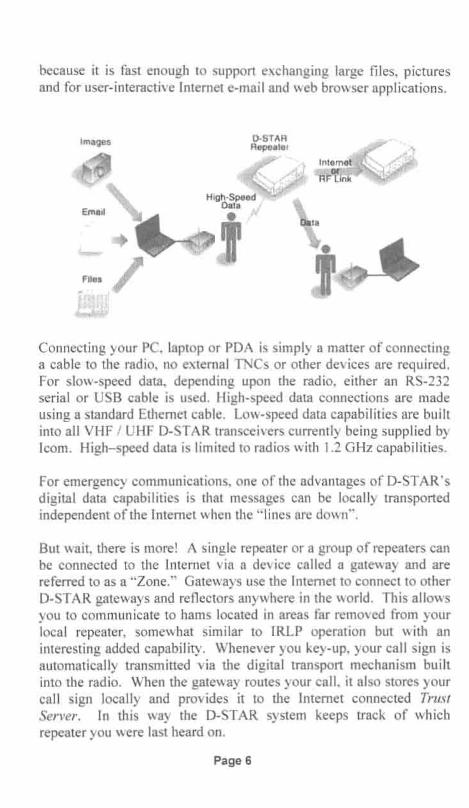
because it is fast enough to support exchanging large files, picturesand for user-interactive Internet e-mail and web browser applications.
Images
tConnecting your PC, laptop or PDA is simply a matter of connectinga cable to the radio, no external TNCs or other devices are required.For slow-speed data, depending upon the radio, either an RS-232serial or USB cable is used. High-speed data connections are madeusing a standard Ethernet cable. Low-speed data capabilities are builtinto all VHF / UHF D-STAR transceivers currently being supplied byleom. High-speed data is limited to radios with 1.2 GHz capabilities.
For emergency communications, one of the advantages of D-STAR'sdigital data capabilities is that messages can be locally transportedindependent of the Internet when the "lines are down" .
But wait , there is more! A single repeater or a group of repeaters canbe connected to the Internet via a device called a gateway and arereferred to as a "Zone." Gateways use the Internet to connect to otherD-STAR gateways and reflectors anywhere in the world. This allowsyou to communicate to hams located in areas far removed from yourlocal repeater, somewhat similar to IRLP operation but with aninteresting added capability. Whenever you key-up, your call sign isautomatically transmitted via the digital transport mechanism builtinto the radio. When the gateway routes your,call, it also stores yourcall sign locally and provides it to the Internet connected TrustServer. In this way the D-STAR system keeps track of whichrepeater you were last heard on.
Page 6

D-STAR Zone
= ReflectorServer
TrustServer
D-STARZone
D·STARZone
T=
ReflectorServer
By entering the call sign of whom you want to contact into yourradio , you can make a directed call to that specific ham. Thetechnique is referred to as Call Sign Routing and unlike IRLP , youdon't need to know which repeater he is on. Periodically all gatewayssynchronize their local data with data located on the Trust Server.The gateway system uses that data to figure out which repeater yourfriend was last heard on and automatically routes your call to thatrepeater. Call Sign Routing can be thought of as being similar to howa cell phone operates. As you travel around, the cell system "knows"where you are at and directs incoming calls to the cell tower nearestto your location . D-STAR works much the same way .
With Call Sign Routing, after entering the call sign of the person youare trying to reach , the D-STAR system can automatically route yourcall to other repeaters, even if they are on a different band or in adifferent city. As a result, no matter which repeater your friend mighthave switched to, your call will be routed to where he was last heard .This solves the problem of having to make calls on all the repeatersthat your friend might frequent.
Page 7
D-STAR's Bits and BytesD-STAR DV mode (slow-speed digital and voice) transceiversproduce an RF signal that is quite different than those produced byconventiona l FM transceivers. The voice portion of the output signalis not FM modu lated; audio is directly converted to a digital datastream using a AMBE (Audio Multi Band Encoder) codec ch ip, inturn the AMBE voice data is combined with other digital data to forma simultaneous composite voice and digital data stream, which is thentransmitted as a GMSK modulated signal.
Within the D-STAR specification, the exact format of this compositedigital stream is defined as the Common Air Interface, or CAlprotocol and is made up of a Radio Header followed by the datapayload. The Radio Header consists of a series of synchronizing andcontrol bits followed by four call signs used to route the signal to itsintended destination . The data payload portion consists of alternatingFrames of Voice and Data information: a frame of 72 bits of voicefollowed by a frame of 24 bits of data , a pattern which continuouslyrepeats until followed by a unique termination frame of 48 bits. Thispattern of alternating digital voice and data frames occurs regardlessif there is voice and no data , or if there is data and no voice. Space inthe payload is always reserved for the voice and data framesregardless of whether they are used or not.
For those interested in the detailed structure of the Common AirInterface protocol and other technical details of the D-STAR overthe-air protocol, an English copy of the JARL specification can bedownloaded from www.jarl.com/d-star/shogen.pdf
A more comprehensive look at the D-STAR over-the-air protocol isprovided by Peter Loveall, AE5 PL in his excellent paper titled DSTAR Uncovered. This paper provides additional insight andinformation beyond what is in the JARL specification, including asummary ofIcom's enhancements to the base specification.http://www.aprs-is.netldownloadsIDStarIDSTARUncovered.pdf
Page 8

Both of the above documents are quite technical , describing the airlink communication protocol in exacting detail and are the basis forhow the system is designed. These documents are primarily ofinterest to those designing D-STAR compatible equipment orsoftware.
If this bits and bytes stuff is all Greek to you, don 't worry, a detailedunde rstanding of the underlying voice and data transmiss ion protocolis not esse ntial for enjoy ing the benefits of D-STAR operation . It 'sreally no different than driving modern automobiles, using computersor accessing the Internet, all of which rely on complex systems and donot necessitate our detailed understand ing before being able tosuccessfully operate them.
Repeater System ConfigurationAs shown below, a typical D-STAR repeater system consists of oneor more repeater modu les that are interconnected via a repeatercontroller, which also supports a connection to the Internet via a PCrunning a D-STAR compatible gateway program under the LINUXoperating system.
D·STAR SYSTEM CONFIGURATION
ID-RP2C (Repeater controller)
ID·RP2V (1.2GHz Digital voice repeate r)
~ 0 ' - cT~ ID-RP2D (1.2GHz Data repeate r)
~] C . -cc 0 .._ -.=~]ID-RP4000V (UHF (440MHz) digital voice repeater)
~ a. -co ""'_~ IID-RP2000V (VHF (144MHz) digital voice repealer)
Page 9
A repeater system can be configured with repeater modulessupporting digital voice on the 144 MHz , 440 MHz and 1.2 GHzbands. A given installation may include any combination of the threevoice modules. Notice that if high-speed digital data is to besupported, a separate 1.2 GHz digital data repeater module isrequired.
A repeater system can be configured without including a PC gatewayserver to the Internet. Of course, the repeater system loses thecapability of communicating with remote gateways and repeaters, butstill provides functionality similar to that provided by conventionalstand-alone FM mode repeaters.
It's common practice to refer to individual repeater modulesconnected to a repeater controller in a D-STAR system as nodes,modules or ports. For example, the four repeater modules shown inthe preceding diagram can alternately be referred to as nodes,modules or ports . Regardless of which term is used , they all refer to aspecific repeater module. The term port is derived from the practiceof referring to individual repeater modules as being connected to arepeater controller's ports .
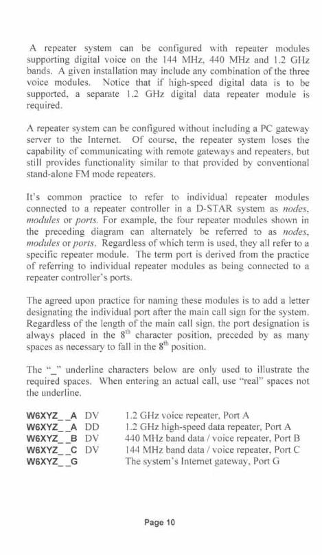
The agreed upon practice for naming these modules is to add a letterdesignating the individual port after the main call sign for the system.Regardless of the length of the main call sign , the port designation isalways placed in the s" character position, preceded by as manyspaces as necessary to fall in the 8th position.
The "_" underline characters below are only used to illustrate therequired spaces. When entering an actual call, use "real" spaces notthe underline.
W6XYZ__A DVW6XYZ__A DOW6XYZ__B DVW6XYZ__C DVW6XYZ__G
1.2 GHz voice repeater, Port A1.2 GHz high-speed data repeater, Port A440 MHz band data / voice repeater, Port B144 MHz band data / voice repeater, Port CThe system's Internet gateway, Port G
Page 10

To avoid confusion as to which local repeater and port you areoperating through, always indicate the port you are on. For example,when making a call through W6XYZ, you would announce "N6FN(using your own call sign) calling on W6XYZ port B."
Notice that the entire repeater system is given a single call sign.Repeater call signs are restricted to a maximum of 6 characters.Individual repeater modules are identified via the port designationsuffix that appears in the 8th character position. Unlike conventionalrepeaters, D-STAR repeater systems must have unique call signs, theycannot be an individual's call sign, otherwise Call Sign Routingwould not be able to function.
Page 11

Programming D-STAR Call Sign ParametersProgramming a transceiver to make calls (or for Iinking to a gatewayor reflector) involves programming call signs into the four parametersof the Call Sign Routing Register:
• UR CALL Call of the station, node or reflector you are calling.• RPT1 Call of the local repeater node you are calling from.• RPT2 Call of a destination repeater or your local gateway.• MY CALL Your own call sign, or call sign variations.
Different transceiver models may display slightly differentabbreviations for these four parameters, but on all radios theyaccomplish the same thing. These parameters are programmed indifferent ways depending upon how you are making the call: simplex,local repeater, Repeater Node or Call Sign Routing, and Gateway orReflector linking .
UR CALL This is either set to the call sign of the station you want totalk to, or is set to CQCQCQ so you can call CQ or work round-tableas on a conventional FM repeater. When using a gateway, UR CALLeither designates the call sign of the individual you are calling, or isused to control gateway linking or for accessing a reflector.
RPT1 Used to enter the call sign of the local repeater you are using .The 8th character position is special as it specifies the band and portyou are operating on. You need to insert spaces as necessary to makesure that the port switch letter (A, B or C) falls in the 8th characterposition.
RPT2 This is the call sign of where we want our transmission to go,either to one of the other ports on the same repeater system, or to thegateway used to access the D-STAR network. Again, the s"character position is special because it is used for the port switchdesignation letter: A, B, C or G.
MY CALL This is used for your own call sign, or perhaps a variationof it with a suffix indicating different radios that you might be using.The differentiating suffix is placed at the end of your call , but mustnot be placed in the s"character position, which is reserved.
Page 12

In this book, the Call Sign Routing Register refers to the current oractive call sign memory that the radio uses to make D-STAR calls.As we will see in Chapter 4, depending upon the radio, there areseveral ways for making entries into the Call Sign Routing Register.
• Man ually editing the current Call Sign Routing Register• Copying from the UrCall , Repeater and MyCall memory banks• Using the [RX-CS] key one-touch reply feature• Recalling a memory channel that has these parameters set
Genera lly you would not want to be programming call signswhenever yo u wish to call someone. And , you certainly don't want toattempt programming call signs while driving. The normal practice isto store in advance all call and repeater node combinations you expectto use into the call sign memories within the transceiver. Once yourtransceiver has been programmed, it's a simple matter of recalling thecorrect ca ll sequence from memory.
Local DSTAR repeater groups typically provide the informationrequired for accessing your local repeaters. In addition, as we shallsee in Chapter 6, there are several web-based resources providing callsign information for D-STAR systems all over the world.
Using D-STAR GatewaysOne of the key features of D-STAR is the ability to communicatewith other D-STAR systems over the Internet. Indeed, connectingrepeater systems via gateways is one of the most powerful aspects ofD-STAR operation. Most of the enhanced capabilities of D-STARrepeater systems rely on their gateway connection.
Since so much can be done via the gateway system, the creators of DSTA R have imp lemented a worldwide gateway user registrationsystem in order to prevent misuse of the resource. Users must registerto be ab le to operate any D-STAR features that involve gatewayaccess to the Internet. Without registration you are generally limitedto simp lex and local repeater operation.
Except for the "Operating Simp lex" and "Local / Same RepeaterOperation" sect ions below, you will need to register for gatewayaccess if you wish to try any of the features described in the followingsections. (Registering is covered in Chapter 3.)
Page 13

Operating SimplexD-STAR transceivers are capable of working station-to-station onsimplex, just like conventional FM transceivers. One advantage of aD-STAR radio is that it's already equipped for digitalcommunications. This can simplify situations when you want totransmit data, perhaps for emergency communications or publicservice events such as aid stations spread along a bike or foot race.Small files in the vicinity of 10k bytes or less can be sent via normalVHF / UHF DV digital mode. If larger file transmissions are required,two 1.2 GHz, 10-1 transceivers can transfer data directly without theuse of a repeater.
Simplex Operation
Voice & Data i
UrCall: coccccRPT1: not usedRPT2: not used
MyCall: WD6FZA
UrCall : cococoRPT1: not usedRPT2: not used
MyCall : N6FN
To talk to anyone on simplex without having to input their call sign,the UrCall field is programmed with CQCQCQ. Since repeaters arenot used when working simplex, depending upon the radio, RPT1 andRPT2 are programmed as "not used" or left blank. And of course,your own call sign is used in the MyCall field.
Here we see that N6FN and WD6FZA, except for their individual callsigns, have their radios set the same way and will be able to talk toanyone that is on the same simplex frequency.
Page 14

Local I Same Repeater OperationWhen working locally on a single D-STAR repeater module, the callsign of the local repeater module is used in RPT1 , and depending uponthe radio, RPT2 can be marked as "not used" or left blank.
Single I Local Repeater Operation
UrCa ll : CQCQCQRPT1 : KIGMGN BRPT2 : not used
MyCall : WDGFZA
• •UrCall : CQCQCQRPT1 : KIGMGN BRPT2 : not used
MyCall : NGFN
In the above example notice that the call sign for RPT1 isKI6MGN_B, which indicates it is a 440 MHz repeater attached toport B of the controller. Using CQCQCQ in the UrCal! field allowsinter-communication between all users on the repeater without havingto enter a specific station's call sign .
With the call signs set as shown, operation is very similar to aconventional FM repeater with everyone being able to hear each otherand participate in the conversation .
Note: So that linked gateways, reflectors and DV Dongle users canhear your traffic, most D-STAR system administrators recommendthat the RPT2 field be set to your local gateway. In the case of thePAPA system KI6MGN repeater, RPT2 would be set to KI6MGN_G.
Page 15

Local Cross-band Repeater Operation
If your local repeater system has two or more modules, you can workcross-band just as if you were operating on a single repeater. In thiscase, RPT1 specifies which repeater you are operating through, andRPT2 specifies the destination repeater. The local repeater controllertakes care of routing the signals between the two ports.
Local Cross-Band Operation
440 MHzRepeater
KI6MGN B
146 MHzRepeater
KI6MGN C \
f-!UrCall : CQCQCQRPT1: KI6MGN CRPT2: KI6MGN B •. " ..
MyCall:N6FN
RepeaterController
~ort
UrCall : CQCQCQRPT1: KI6MGN BRPT2: KI6MGN C
MyCall: WD6FZA
In this example WD6FZA is going through the KI6MGN_B, 440MHz repeater, and N6FN is going through the KI6MGN_C 146 MHzrepeater. It is important that the port switch designation (the letters Band C in this case) is programmed into the 8th character position.
Notice that since the two stations involved are on separate repeatermodules serviced by the same repeater controller, a gateway is notbeing used, and that the call signs they programmed into RPT1 andRPT2 of their radios are reversed.
When the station hearing the call , in this case N6FN, wants torespond he needs to set his radio 's RPT2 field to the radio modulebeing used by the calling station, in this case KI6MGN_B. But keepin mind that the calling station needs to identify which module he ison so the answering station can configure his radio to the repeatermodule that the calling station is using.
Page 16

Repeater Node RoutingRepeater Node Routing, also called "Source Routing," "Port Linking"or a "Zone Call" allows the user to specify a specific repeater node asthe destination for his transmission. This can be used to place a callto a specific ham or perhaps as a way of announcing your presence orcalling CQ on a distant repeater.
Using this method a user can either send his signal to a different porton the same repeater system or to any gateway connected repeaternode in the world.
Repeater Node Routing
440 MHzRepeater
KI6MGN B
•
I
UrCall : 1W301 CRPT1: KI6MGN BRPT2: KI6MGN G
MyCall : N6FN
146 MHzRepeaterW30lC
•UrCall : IKI6MGNB IRPT1:W301 CRPT2 : W301 G
MyCall : W3XXX
To use Repeater Node Routing a " / " is placed in front of thedestination repeater's call sign in the Ureal! field. The leading " / "character lets the controller know you are making a call to a specificrepeater node and that it's not the call sign of a person .
Note : After N6FN made his call to the W30I C repeater, W3XXXconfigured his radio using Node Routing to route his call back toN6FN 's repeater, KI6MGN_B. The "G" suffix in the s" characterposition of the RPT2 field indicates that the signal is to be routed tothe gateway.
When someone answers a call made using Node Routing, they mustconfigure their radio to route their signal back to the repeater modulethat the source radio is using . Therefore, as is generally the casewhen using D-STAR, the calling station needs to identify whichrepeater and port he is calling from.
Page 17

A receiving station, in addition to hearing the transmitting stationidentify the repeater he is calling from, can also examine the ReceivedCall memory on his radio . Refer to the Received Call Historyprocedure in Chapter 4 for details on how to examine the ReceivedCall memory.
When you are finished with your QSO on the remote repeater youneed to change the UrCal! field back to CQCQCQ, otherwise whenmaking any further contacts, even on your local repeater, your voicewill still be routed to and heard on the remote repeater indicated in theUrCal! field. This is an easy mistake to make and I suppose everyonehas done it at one time or another.
I supposedly know better, but here is how easy it is to make amistake. Hearing Toshi JFICXH, a Japanese station, calling on ourlocal D-STAR repeater, I configured my radio for Node Routing backto his repeater by placing his local repeater call sign, IJPIY IQA intomy radio's UrCal! field. So far so good and the QSO went fine .
The problem "snuck in" after my QSO with Toshi in Japan ended.Just as I signed off with Toshi , I was immediately called by anotherstation on my local repeater. Not thinking, I returned his call and wechatted a bit about making contacts to Japan and a few other topics.Only after finishing the follow-on QSO did I remember that I hadneglected to switch my UrCal! field back to CQCQCQ. The result wasthat my side of the follow-on conversation was broadcast in Japan! Iwas the cause of several minutes of unintended interference on theirrepeater. Not good!
This can happen when using any of the D-STAR modes where youare either routed to or connected to a remote repeater or reflector. Itsimportant to remember to reconfigure your radio 's UrCal! field and ifnecessary also the RPT1 and RPT2 fields back to where they need tobe to prevent "interference" on a remote repeater node. Stay alert anddon 't let this happen to you.
Page 18

Call Sign RoutingWith Call Sign Routing, also referred to as User Linking, you canmake a call to a specific ham without having to know what repeatersystem he is on. Providing a ham has registered for gatewayoperation, whenever he transmits on a gateway-equipped system, theD-STAR gateway system's database is updated with the repeatersystem module he was last heard on .
When you make a directed call to a specific amateur's call sign, thegateway system automatically routes your call to the repeater modulewhere that station was last heard.
Call Sign Routing
440 MHzRepeater
KI6MGN B
0:::)Gateway "-~J Gateway
146 MHzRepeaterW30lC
• UrCall: W3XXXRPT1: KI6MGN BRPT2: KI6MGN G
MyCall:N6FN
UrCall : N6FNRPT1: W301 CRPT2: W301 G
MyCall: W3XXX
In this example Call Sign Routing is being used by N6FN to locateand talk to W3XXX, which happens to be on the W30I C moduleat the moment. Notice that W3XXX has set his UrCall field toN6FN 's call sign to answer his call. The other three fields wereprobably already set since he has recently been using the W30I Crepeater.
Before the ham you are calling can respond, he needs to program hisradio's UrCall register with your call. The responding station canmanually enter your call into his radio (or select it if already has it inmemory) or he can use the [RX-CS] "one-touch" key on his radio, if ithas one. The more recent D-STAR capable transceivers have theone-touch capability to copy a received station's call sign to theUrCall field.
Page 19

Using the one-touch reply [RX-CS] key only temporarily copiesN6FN's call sign into the UrCall field , and will last until somethingelse is placed into the UrCall field. It's not permanently savedanywhere. One-touch operation is described in the following section.
Note that both stations have set RPT2 to their local gateway. Doing sohas allowed the gateway system to rout 6FN's call to the lastrepeater module that W3XXX has been heard on. As a side note, italso allows Dongle users to hear both sides of the conversation.
One of the issues with Call Sign Routing is that the " last heard on"process can take an hour or more to update the database; therefore theuser may no longer be on that repeater.
One way to partially get around the problem, so that you canimmediately receive calls when away from your local repeater, is assoon as you are on another D-STAR repeater system place a call backto your local repeater. Then at least your local repeater system willimmediately know what repeater you are on, and if anyone calls youfrom there using Call Sign Routing, their call will be forwarded towhere you are at.
Of course, if your friend is using CQCQCQ in the UrCall field whenoperating on your local home repeater, you will not receive any callsdirected to you unless he knows you are out of town and switchesover to Call Sign Routing by entering your call sign into his UrCall
field .
By the way , if out of town , what method do you use to call back toyour home repeater system? You have a couple of choices: you couldeither use Call Sign Routing if you wanted to call a particular station,or if you just wanted to check in with a general call on your homerepeater you could use Repeater Node Routing.
When you are done talking with your friend you need to change yourUrCall field back to CQCQCQ, otherwise when making any furthercontacts, even on your local repeater, your voice will still be routed toand heard on the remote repeater where , your friend was lastoperating.
Page 20

Doubling using Repeater Node or Call Sign RoutingA point to keep in mind when using Repeater Node or Call SignRouting is that when using these modes you do not "hear" any trafficoccurring on the distant repeater module. Digital packetsrepresenting your transmissions are routed to the distant repeater; youare not actually connected or linked to the repeater. Consequentlythere is a possibility that your call might double with traffic occurringon the distant repeater. You will only hear transmissions from aresponding station, if he has set his Ureal! field to either your call signor the ca ll sign of the local repeater node you are using.
If your transmission should inadvertently double with existing traffic,the distant repeater's controller inhibits your transmission, preventinga double, and returns an error message: RPT?AA6AAA, with the callsign of your loca l node following the question mark . When yourradio receives the error message, it is scrolled on the display. If yousee this message, wait a bit and try your call again.
One of the advantages of Dplus, discussed in the following chapter, isthat the potential for doubling with traffic on a distant repeater can beovercome by " link ing" to distant repeaters. Dplus linking is differentthan Repeater or Node Routing, because you hear all traffic on thedistant repeater, and can thus time your calls, just as you would on anormal FM repeater.
Page 21

Setting the UrCal! field back to CQCQCQ
As we have seen , its important to change your radio 's UrCal! call signrouting fie ld back to CQCQCQ after setting it to something else formaking calls to specific stations, repeaters or sending linkingcommands as we will see in the next chapter.
Setting UrCal! field to CQCQCQ on the IC-80AD:
I . Starting with the DV operating mode selected and a 0STAR repeater frequency being displayed on the screen.
2. Whi le holding [0/ UR] rotate [DIAL] to select CQCQCQ .
Setting UrCal! field to CQCQCQ on the ID-880H:
I . Starting with the DV operating mode selected.
2. Press front panel [UR] Isec
3. Rotate [DIAL] to select CQCQCQ, Press [UR] again to exit.
Setting UrCal! field to CQCQCQ on the IC-91AD and IC-92AD:
I. Starting with the DV operating mode selected and a 0STAR repeater frequency being displayed on the screen.
2. Press [0/ CQ] until you hear a beep , then release.
Setting UrCal! field to CQCQCQ on the IC-2820:
1. Starting with the DV operating mode selected.
2. If necessary, press [F] twice to access the DV modefunct ion keys . (CS CD CQ R>CS etc .)
3. Press [CQ] to set the UR field to CQCQCQ .
To set CQCQCQ on other radios, refer to the leom user manual.
Page 22

One-touch ReplyThe one-touch feature, available on newer model leom transceiversthat have the [RX-CS] key, is a handy way of responding to a call. Asca lls are received they are automatically stored in the Call Historymemory and are available for use by the one-touch feature. Pressingthe [RX-CS] key sets the radio to respond to the most recent callrece ived by copying the caller's call sign to the UR call field.
However, if another call is rece ived after the one you want to respondto, you wi ll need to select the desired call from the Received CallHistory memory as show n in step 3 below.
Be aware, that if the repeater produces a transmission after the desiredca ll was received, one-touch may copy the repeater's gateway callsign to the UrCal! fie ld. If so, skip step 2 and use step 3 to select thedesired ca ll.
Important: After using the one-touch feature to make a reply, be sureto change yo ur radio's UrCal! field back to CQCQCQ .
Using One-touch on the IC-SOAD, IC-91AD and IC92AD:
1. First make sure that your own call sign has been set into theMY call field and that RPT1 and RPT2 are set for Call SignRouting from your local repeater.
2. (On ly use Step 2 or 3) After a call has been received, pressand hold the [RX-CS] key one second to set the Call SignRouting Register to respond to the most recently receivedcall.
3. Or if you want to select a ca ll sign from a list of recentlyreceived call signs, press and hold the [RX-CS] key androtate [DIAL] to select the desired call sign record. Recentlyreceived call signs stored in the Call History Memory aredisp layed on the scree n.
4. Everything is now set; press [PH] to transmit.
Page 23
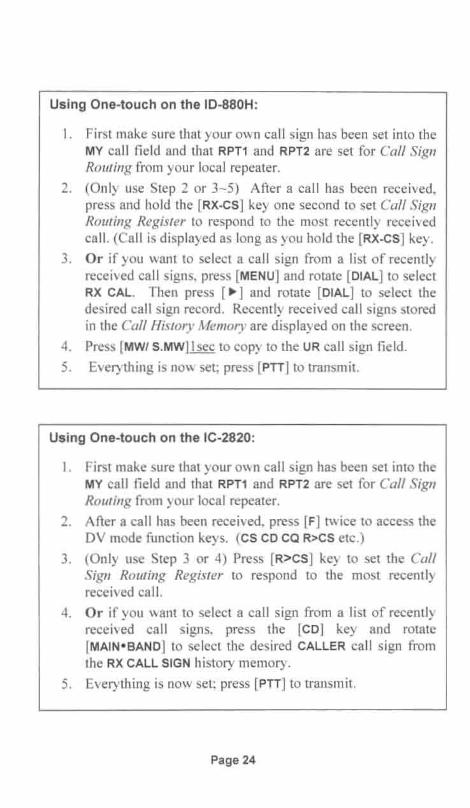
Using One-touch on the ID-880H:
I. First make sure that your own call sign has been set into theMY call field and that RPT1 and RPT2 are set for Call SignRouting from your local repeater.
2. (Only use Step 2 or 3-5) After a call has been received,press and hold the [RX-CS] key one second to set Call SignRouting Register to respond to the most recently receivedcall. (Call is disp layed as long as you hold the [RX-CS] key .
3. Or if you want to select a call sign from a list of recentlyreceived call signs, press [MENU] and rotate [DIAL] to selectRX CAL. Then press [ ~] and rotate [DIAL] to select thedesired call sign record. Recently received call signs storedin the Call History Memory are displayed on the screen.
4. Press [MWI S.MW] Isec to copy to the UR call sign field.
5. Everything is now set; press [PTT] to transmit.
Using One-touch on the IC-2820:
I . First make sure that your own call sign has been set into theMY ca ll fie ld and that RPT1 and RPT2 are set for Call SignRouting from your local repeater.
2. After a call has been received, press [F] twice to access theDV mode function keys. (CS CD CQ R>CS etc .)
3. (Only use Step 3 or 4) Press [R>CS] key to set the CallSign Routing Register to respond to the most recentlyreceived call.
4. Or if you want to select a call sign from a list of recentlyreceived call signs, press the [CD] key and rotate[MAIN- SAND] to se lect the desired CALLER call sign fromthe RX CALL SIGN history memory.
5. Everything is now set; press [PTT] to transmit,
Page 24

Automatic Call Sign Update Preventionleom's D-STAR radios have two menus that can enable received callsigns to automatically replace call signs in the Call Sign RoutingRegister. In general you don't want this to happen, so you shouldverify that they are turned OFF, which is the default setting for thesetwo menus.
The " RX Call Sign Auto Write " menu should be set to OFF toprevent having received station 's call sign automatically replace yourUrCal! setting. The default sett ing is OFF.
The "Repeater Call Sign Auto Write " menu should be set to OFF toprevent having rece ived station's RPT 1 and RPT2 call signsautomatically replace your RPTI and RPT2 settings. The defaultsetti ng is OFF.
Multicast GroupsMulticast is a feature that leom added with the G2 version of thegateway software. Multicast allows an administrator to associate agroup of repeater nodes with an alias (a name of his choosing). Usinga Multicast gro up name allows an administrator to route transmissionsbetween as many as 11 repeater nodes. Multicast group names of upto seve n characters long always start with the character " l ", Whenthis name is referred to , it has the same effect as referencing all of therepea ter nodes in the network at once.
UR CALL:RPT1 :
RPT2:MY CALL:
/CA 1200WR6BRN CWR6BRN GN6XXX
Multicast group name .Local module you are linking from.Gateway for local repeater module.Your own call sign.
While users don 't have the capability of creating Multicast Groups,they can make use of the feat ure by placing the group name in theirUrCal! field. When a user transmits using a Multicast group name, hewi ll be heard on all the repeater nodes in the group. The user 's localgateway accomplishes this by sending a stream of data to each of thenodes in the group.
Page 25

So that users on remote repeaters can respond, it is important toannounce the repeater you are calling from and the Multicast Groupname being used . If responding stations don't use the Group name intheir UrCal! field , they will not be heard on all the repeaters in thenetwork.
Important: At the end of the round table or net and going back tonormal operation, it is important that each station terminate multicastoperation by resetting their UrCal! field back to CQCQCQ or somethingelse. Otherwise, their transmissions will still go out to the entiregroup of repeaters.
Page 26

Identify Where You Are Calling From and WaitWhenever making ca lls on a D-STAR system it is imperative that youidentify the repeater and port you are calling from. Otherwise whena stat ion hears your call he won't know if you are local or elsewhere.If yo u are not on his local repeater he may need to know where youare transmitting from in case he needs to change the settings in hisUreal! and RPT2 call sign fie lds.
Typically you would state the location of the repeater and which portyo u are on . For instance if operating on the PAPA system MountPalomar repeater you might say that you are "using Mount PalomarKI6MGN port B."
This brings up the second point to remember when making calls overthe D-STAR system. After making a call, monitor long enough for aresponding stat ion to make any radio changes necessary. Since it islikely that the responding station was otherwise preoccupied, it maytake a few minutes for him to "put down" what he was doing, changehis radio settings and return your call. Repeating your call once ortwice (don't get carried away here like calling CQ on HF) may allowthe station to make note of where you are at so he can make therequired settings .
On repeaters with frequent traffic, you may also want to holdtransmission a sufficient amount of time to allow a receiving stationto use his "o ne-to uch rep ly" key to copy your call sign information tohis radio ' s D-STAR ca ll sign fields . Remember, he has to hear yourcall, pick up his radio and then press the key . If your call is too short,by the time he is ready to press the key your signal may have beenpushed down in the stack of calls in the Call History Memory.Remember, one-to uch retrieves the most recent call from the CallHistory Memory.
Page 27

Limiting Position Beaconing and Data Mode OperationWhenever multiple D-STAR repeater nodes are linked together forgroup, emergency or net operations, via Multicast or the Dpluslinking methods described in the next chapter, automatic APRS /DPRS GPS position beaconing should be turned off or be set totransmit only on PTT. Automatic beaconing every few minutes willresult in data being transmitted to all connected nodes, causingcollisions (doubling) with other user's transmissions.
Likewise, for the same reason , consider delaying DV data modetransmission unti l the net is over or switch to another repeater system.While data can be sent along with a voice transmission, if automaticdata transmission has been selected, it won 't wait for a voicetransmission to occur. It will occur anytime data is ready to be sent.
Page 28

Chapter 2: Dplus Gateway OperationDplus is an auxiliary gateway operating system program used to routeca lls and establish links between D-STAR repeater nodes. Dplusadds features to gateway operation beyond those provided by lcom ' sG2 gateway software. Because of its enhanced capabilities, Dplus,written by Robin Cutshaw, AA4RC is almost universally installed onall gateways outside of Japan. If installed on your local gateway,among other things, it provides Gateway and Reflector linkingcapabilities as well as an Echo Test and a means of verifying linkstatus.
As a side note , the Dplus gateway software is periodically upgradedas new features are added. While the installation and maintenance ofthe Dplus software is performed by your system administrators, newfeatures , which may affect operation, could be introduced at any time .If so, your system administrator will notify you of any operationalchanges that may need to be made.
Page 29

Dplus Gateway Linking
With Dplus installed, it 's possible for a user or a system administratorto initiate a link between two repeater modules residing on differentgateway systems.
•O·STARGateway
••
• • •
Once a link has been established, all users on the two linked repeatermodu les can contact each other in a manner similar to conventionalFM repeaters that have been linked together. When any station onone repeater transmits, all stations on the remote gateway linkedrepeater hear that transmission. The system takes care of routingsignals back and forth and users should not use any special routing.Their UrCal! sign configurations should be set to CQCQCQ and RPT2should be set to the call sign of their local gateway with a "G" in the8th character position, just as if they were making local calls.
Depending upon the system in your area, you may find repeater nodeslinked together temporarily or semi-permanently, either by individualusers or by a system administrator.
Some systems may not allow individual users to perform linkingoperations . Esta blishing a link sho uld not be attempted without firstcontacti ng the administrators of a D-ST AR system to find out if it isallowed and to dete rmine any procedures they want used.
Page 30

Establishing a Dplus Gateway LinkAdmi nistrators can establish links via their command line controlsystem for the gateway. If enabled on their local repeater system,users can establish a gateway link to another repeater by sett ing theUrCal! fie ld to the call of the remote repeater followed by the letter"L" in the 8th character position to signal that you wish to establish alink.
Step 1. Programming Call Signs for making the link:For example, if you are currently located on the 2-meter module ofthe WR6 BRN system and wanted to link to the 70cm module of theKI6MGN_B system, the Call Sign Routing Register would be set asfollows :
UR CALL:RPT1 :
RPT2:MY CALL :
KI6MGNBLWR6BRN CWR6 BRN GN6XXX
Repeater module B you are linking to .Local module you are linking from .Gateway for local repeater module.Your own call sign .
Step 2. Key up and identifyOnce you have programmed the call field s for making the link , keyup and state your intention: "N6XXX, activating link to KI6MGNmod ule B".
Step 3. Change UrCall back to "CQCQCQ"When you hear a voice announcement saying, "Remote System isLinked." the link is established. Before trying to make anycontacts, change your radio 's UrCal! field back to CQCQCQ. If youdon 't do this , the system will attempt to re-establish the link everytime yo u transmit. While this is not catastrophic, it does burden thesystem with unnecessary activity.
UR CALL: CQCQCQ Set to communicate with any station.
You mig ht also hear another message: "System Currently Linked,"which means that the repeater you are trying to link to is alreadylinked to somewhere else, or that you didn't change your radio'sUrCal! field back to CQCQCQ.
Page 31

Step 4. Un-Link at the end of the QSOYou must remember to unlink the repeaters when you are finished.As a practical matter, any station can terminate the link, it doe s nothave to be the originator of the link . To terminate the link , set theUrCal! field as shown below. (Seven spaces followed by the letter"U".)
UR CALL: U Place a "U" in s" character position .
You might also hear another message: "System Not CurrentlyLinked," which occurs if you try and unlink, but the repeater is notcurrent ly linked. This can be used to verify that the repeater isindeed unlinked .
Dplus Reflector LinkingGateways equipped with Dplus can use Internet connected reflectorsfor linking multiple repea ter nodes together, permitting conversationsamong all users on the linked nodes. The reflector acts as a centralconferencing hub, which is the key element that enables linkingmult iple D-STAR repeater nodes together.
O-STAR Zone=
-- r- -c7~ - )
.,.;r -
ReflectorServer
TrustServ er
Page 32
O-STAR Zone
=-- -:::---- ......,-- - )..,;;rI
O-STARZone
=, ~7 ~
__ - I
.,,;,- ..... ;.:
<. 41
Refl ecto rServer

Reflectors are a special type of Internet connected gateway that" reflects" DV mode voice and data back to all linked nodes. Whenthe reflector receives a transmission from one of the linked nodes, itrebroadcasts it to all of the other linked nodes. The effect of this isthat all users on all linked nodes are able to hear and talk to each otherwithout having to change their radio 's Call Sign Routing Registersettings. All users should leave their radios set for local repeateroperation.
Reflector links are often set up for wide area nets and for emergencycommunications. Repeaters are generally linked and unlinked fromreflectors by system administrators, however some D-STAR systemsalso allow their users to establish links .
If a Reflector Link has been established, users on any of the linkednodes can talk and hear each other without having to modify theirradio's UrCal! field. The settings normally used for local repeateroperation will work, providing the RPT2 field is set to the call sign ofthe local gateway with "G" set in the 8th character position as shownbelow.
UR CALL:RPT1:
RPT2:MY CALL:
CQCQCQWR6BRN CWR6BRN GN6XXX
Set to CQCQCQ for reflector use.Local module you are operating on.Gateway for local repeater module.Your own call sign.
As of late 2009 there were 26 reflectors worldwide, REFOO I throughREF026, and more are being added as time goes on. Each reflectorhas three modules, A, Band C, each of which can support the linkingof different groups of repeater nodes together. A reflector's modulescan all be active at the same time and are somewhat like having threedifferent conference rooms, each supporting their own group oflinked repeater nodes.
Page 33
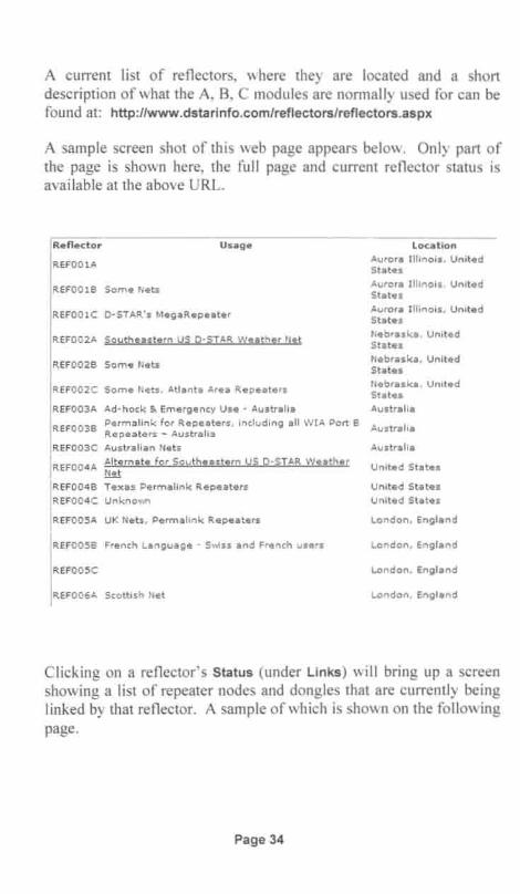
A current list of reflectors, where they are located and a shortdescription of what the A, B, C modules are normally used for can befound at: http://www.dstarinfo.com/reflectors/reflectors.aspx
A sample screen shot of this web page appears below. Only part ofthe page is shown here, the full page and current reflector status isavailable at the above URL.
IReflector Usage
IREF0 0 1A
IREF0 0 1B Some Ne t s
IREF0 0 1C D-STAR's MegaRepeat er
IREF0 0 2A Southeast ern US D-STAR VVeather Net
IREF0 0 2B Som e Nets
IREF0 0 2 C Some Ne ts. Atlanta ;'.rea Repe a t e rs
IREF0 0 3A Ad-hock 5< Emergen c)' Use - Australia
I
REF0 0 3B Permalink for Repea ters , in clu d in g all W I ll. Port BRepeaters - Australia
IREF0 0 3C Aus tralian Ne ts
I
REF0 0 4A Alt ernat e for Southeas tern US D-STAR WeatherNet
IREF0 0 4 B Tex as Permalink Re p ea t e rs
IREF0 04 C Unkno wn
IREFOOSA UK Ne ts , Pe rma link Repeaters
IREFOOSB French La n gu a ge - SvJss and Fre nch u s e rs
IREFOOSC
IREF0 0 6 A Scottish Ne t
location
Aurora I ll in o is, Un itedStates
Aurora I ll in o is, UnitedStates
Aurora Illinois, UnitedStates
Ne b raska , Un it e dSt at e s
Ne b ra s k a, Un ite dStates
Ne braska. UnitedStates
Australi a
Australia
Au st ra lia
United States
United States
United St a te s
Lo n d o n, Eng la n d
London, England
London, En g la n d
London, England
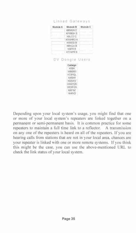
Clicking on a reflector' s Status (under Links) will bring up a screenshowing a list of repeater node s and dongles that are currently beinglinked by that reflector. A sample of which is shown on the followingpage .
Page 34
L inked Gate ways
, Modull,'A Modu!ii'S ' Module C-'I KJ6MGNC' i
i KF6BOKB, K8lCDC
KW6HROA 'r --, K6MDDB c
c' KJ6KOlf f:J- ,--,K61FR B
KT7APRB
DV Dongle Users
' Callslgn'K6BICWB8REi'KC8YOLki6NHY'KM6AW
WMVGRWDeFlAki6FNT'AHi3kbj
Depending upon your local system's usage, yo u might find that oneor more of your local system's repeaters are linked together on apermanent or semi-permanent basis. It is common practice for somerepeaters to maintain a full time link to a reflector. A tran smi ssionon anyone of the repeaters is heard on all of the repeaters. If you arehearing calls from stations that are not in your local area, chances areyour repeater is linked with one or more remote systems. If yo u thinkthis might be the case, you can use the above-menti oned URL tocheck the link status of your local system.
Page 35

Establishing a Reflector LinkIf your local repeater system allows users to establish links , here isthe procedure. The procedure is exactly the same as for Dplus linkingof two repeaters, except the name of a reflector module instead of acall sign is used in the UrCall field ,
Step 1. Programming the command for linking to a reflector:For example, if you were currently located on the 2-meter module ofthe WR6BRN system and wanted to link to the REFOO IC reflector,the Call Sign Routing Register would be set as follows :
UR CALL :
RPT1:RPT2:
MY CALL :
REFOOICLWR6BRN CWR6BRN GN6XXX
Reflector module you are linking to.Local module you are linking from.Gateway for local repeater module.Your own call sign .
Step 2. Key up and identifyOnce you have programmed the call field s for making the link , keyup and state your intention: "N6XXX, linking to Reflector 00 Imodule C".
Step 3. Change UrCal! back to "CQCQCQ"When the link is estab lished, you will hear a voice announcementsaying, "Remote System is Linked," you then need to change theUrCall field back to CQCQCQ. If you don 't do this, the system willattempt to re-establish the link every time you transmit.
UR CALL : CQCQCQ Set to communicate with any station.
Step 4. At the end of the linked session , Un-linkWhen the linked session is complete set the UrCall field as shownbelow to terminate the link. (Seven spaces followed by the letter U.)
UR CALL : U Place a " U" in 8th character position.
If the command was accepted you will hear a voice announcing"Remote System is Un-linked."
Step 5. Change UrCall back to CQCQCQ
Page 36

Local SimulcastLocal Simulcast allows you to simultaneously transmit on all the localrepeater system modules attached to a given controller. In a full stacksystem, there would be three voice modules, one for each of thebands: 2m, 70cm and 23 em .
Local Simulcast
•
440 MHzRepeater
KI6MGN B
UrCall : KI6MGN __RPT1: KI6MGN _BRPT2: KI6MGN_G
MyCall : WD6FZA
1.2 GHzRepeaterKI6MGN A
GatewayServer
146 MHzRepeater
KI6MGN C
To transmit on all of a repeater system's local modules, programUrCALL with the gateway call sign followed by however many spacesare required to fill all 8 positions. Note that in this case, trailingspaces are important, without them the controller will not "know" thatthis is a simulcast request.
If other stations on the repeater system also have their radios set forsimulcast, users on all of the repeater modules can talk to each other.
Page 37

Echo Audio Quality TestingEcho audio testing is a handy feature of Dplus equipped gateways.Users can make a short transmission, and after unkeying a recordingof your transmission will be played back. Besides being a usefulcheck of your audio transmit quality, it can also be used to verify thatyour local repeater modules and gateway are operating normally. Ifyour system has multiple modules, you could perform a check of eachof them using the Echo test. If all is working OK, each module will"hear" your transmission, digitize it and pass it to the gateway serverwhich will delay it a bit and send it right back.
Echo Test
GatewayServer
440 MHzRepeater
KI6MGN B
UrCal! : KI6MGN_ ERPT1: KI6MGN_BRPT2: KI6MGN_G
MyCal! : WD6FZA
To run an Echo Test, set the Ureal! field to the call sign of the repeatersystem you are on, followed by the letter "E" in the 8th characterposition . The other fields are set as normal for local repeateroperation. In this case , RPT1 is set to port B for testing the 440 MHzmodule. Other ports on your local system can be checked the sameway.
Page 38

Checking Repeater Link 110 StatusDplus also comes with the ability to query the repeater to determine ifit is linked or not. When the command is transmitted to the repeater,it will respond verbally with the current link status. The exact formatof the vocal message may vary on different systems as the systemadministrator can modify the message sound file . This feature maynot be avai lable on all systems.
The link status message may communicate that the repeater module iscurrent ly unlinked, or that it is linked to a repeater or reflector.
To perform an ID / Link status check, program the repeater's call signinto the UrCall field with the letter "I" in the s" character position.The remain ing call fields are configured as usual for normal repeateroperation as shown below.
UR CALL:RPT1:RPT2:
MY CALL :
WR6BRN 1WR6BRN CWR6BRN GN6XXX
ID / Link Status command.Local module you are operating on.Gateway for local repeater module.Your own call sign.
Page 39

Page 40
Chapter 3: Gateway User RegistrationRegistration is required to use the Internet D-STAR Gateway system.Once your registration is approved, the gateways will recognize yourcall sign and the Trust Server will keep track of the repeater nodesyou were last heard on. Without registration you are generallylimited to local repeater node operation.
Getting RegisteredOn most systems registration is a two-step process. The first step isproviding the required registration information, which will bereviewed by a system admin istrator. The second step occurs whenyou receive notification from the administrator that your registrationhas been approved and you can start using the gateway system. Aspart of the process, the administrator may also provide you withinformation for becoming a member of the local repeater organizationand instructions for operating the system.
Registration is a simple process, with most local D-STAR systemshaving provisions for doing it on-line. Contact your local systemadministrator to find out how they want you to register. Typically allthat is required is:
• Your call sign (and perhaps a copy of your FCC license)
• Name• Home address• E-Mai l address• If registering on- Iine, a password for accessing your account
If your local system supports on-line user accounts, after approvalyou will be given a web page URL for you to log on and setup yourpersonal account. Initially yo u will need to enter a call sign for usewith your radios. If you are going to operate multiple radios whichmay be in use at the same time , additional call sign variants can beentered by adding a one-letter suffix, separated by a single space, tothe end of your ca ll. Your first entry need not have a suffix appendedto your call sign. For example: W6XYZ A. (the _ indicates thespace .)
Page 41

Call sign variants may also be desired for implementing unique CallSign Routing capabilities. Call Sign Routing will treat each variant asa unique call sign. Additional variants are required if you will beusing more than one 1-0 I transceiver in the digital data mode .
For each call sign variant that you enter, the system assigns an IPaddress used to identify you. An IP address is a unique InternetProtocol identification number assigned to devices communicating onthe network. Valid call sign suffix characters, which must be placedat the end of your call, can consist of any capital letter , (no numbers)except that they may not be placed in the 8th character position. The8th position is reserved for the D-STAR call sign switches: A, B, C 0 ,G, S and I. To be able to use the system you need to make an entryfor at least one radio.
Note : Only register once, usually via the registration facilitiesprovided by your local D-STAR gateway system administrators. Thiswill allow you to have access to the entire D-STAR network. Even ifyou travel to other areas , the repeater gateways will still recognizeyour call. If you register a second time , either on the same gatewayor from any other gateway system , you may confuse the system.
Registration actually occurs on your local gateway. That gatewaypasses your registration information onto the Trust Server, which inturn propagates it to all other gateways in the D-STAR System. Thuswhen you register on one gateway, you are automatically registeredon all the gateways in the network.
Generally you should be able to either self-register or find out whomyou need to contact via the Internet. Start by accessinghtt p://www.dstarusers.org/repeaters.php and finding the repeatersystem closest to you. The list found on this page can be sorted byrepeater call sign, city or state by clicking on the heading at the top ofthe list.
Page 42

After yo u have fou nd the repeater system closest to you , click on itsca ll sign to display detailed information about the repeater. Clickingon the URL following Gateway Registration URL: will take you to theregistration web page for that system . If this URL is not present, goto the web page fo llowing Website: and either look for registrationinfo rmation on that web page, or look for a person to contact.
Ano ther resource is to follow the instructions found athttp://www.dstargateway.orglD-Star_Registration.htmI This web pagealso has a sample registration form and instructions on how to fill itout.
If after tryi ng the above resources, you are still unable to figure outwhom to contact, try the following :
• Me mbers in yo ur ham radio club• Yo ur nearest ham radio store• Yo ur local ARRL Section Manager
List of a ll Section Managers can be found at:http://www.arrl.org/FandES/field/org/smlist.html
Page 43

Page 44

Chapter 4: Setting Up Call Sign Memories
In Chapters I and 2 we covered different methods of making calls,and the format of the Call Sign Routing Register fields for makingthose calls. Here we examine how the call sign memories of a typicalradio are organized and programmed. We will use the IC-92AD as anexa mple, and also provide programming instructions for the IC80AD, IC-9l AD, ID-880H and the IC-2820. Other leom D-STARradios have essentially the same functions and can be similarlyprogrammed.
Call Sign MemoriesIn Chapter I we exp lained how the radio uses the Call Sign RoutingRegister to make D-STAR calls. The Call Sign Routing Registercontains the now familiar set of parameters that are used to controland route D-STAR calls:
• UR CALL Ca ll of the station, node or reflector you are calling.• RPT1 Call of the local repeater node you are calling from .• RPT2 Call of a target / destination repeater or your gateway.• MY CALL Your own ca ll sign, or call sign variations.
Depending upon the radio, there are several ways for making entriesinto the Call Sign Routing Register.
• Manually editing the current Call Sign Routing Register• Copying from UrCall, Repeater and MyCall memory banks• Recalling a memory channel that has these parameters set• Using the [RX-CS] One-touch feature
Page 45
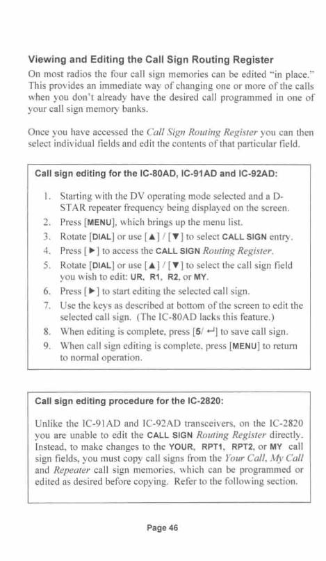
Viewing and Editing the Call Sign Routing Register
On most radios the four call sign memories can be edited "in place ."This provides an immediate way of changing one or more of the callswhen you don't already have the desired call programmed in one ofyour call sign memory banks.
Once you have accessed the Call Sign Routing Register you can thenselect individual fields and edit the contents of that particular field .
Call sign editing for the IC-80AD, IC-91AD and IC-92AD:
I. Starting with the DV operating mode selected and a D-STAR repeater frequency being displayed on the screen.
2. Press [MENU], which brings up the menu list.
3. Rotate [DIAL] or use [.A.] / [ T] to select CALL SIGN entry.
4. Press [ ~ ] to access the CALL SIGN Routing Register .
5. Rotate [DIAL] or use [.A.] / [T] to select the call sign fieldyou wish to edit: UR, R1, R2, or MY.
6. Press [ ~] to start editing the selected call sign .
7. Use the keys as described at bottom of the screen to edit theselec ted call sign. (The IC-80AD lacks this feature.)
8. When editing is complete, press [5/ ...-J] to save call sign .
9. When call sign editing is complete, press [MENU] to returnto normal operation .
Call sign editing procedure for the IC-2820:
Unlike the IC-91AD and IC-92AD transceivers, on the IC-2820you are unab le to edit the CALL SIGN Routing Register directly.Instead, to make changes to the YOUR, RPT1, RPT2, or MY callsign fields , you must copy call signs from the Your Call, My Calland Repeater ca ll sign memories, which can be programmed oredited as desired before copying. Refer to the following section.
Page 46

Call sign editing for the ID-880H :
1. Starting with the DV operating mode selected and a DSTAR repeater frequency being displayed on the screen.
2. Press front panel [CS] to access the call sign registers .
3. Rotate [DIAL] to select the call sign field you wish to edit:UR, R1, R2, or MY.
4. Press [ ~] twice to start editing the selected call sign.
5. Rotate [DIAL] and use the [ .... ] / [ ~] keys as required to editthe call sign as usual for the lD-880H.
6. When finished editing, press [ ...-J] to save.
7. Repeat step 3 if you wish to edit another call sign.
8. When done editing, press [CS] to exit and return to normaloperation.
Note: When operating in DR mode, only the MY call sign fieldcan be edited .
Page 47

Copying from UrCall , Repeater and MyCall Memory BanksFirst lets examine the relationship of the UrCall, Repeater andMyCall memory banks to the Call Sign Routing Register.
IC-92A Call Sign Memo ry Bank Organization
Ur Call SignMemory
UR:Rl :R2:
MY:
60 Memories
UOl thru U50
Rep ealer CallSign Memory
50 Memories
R011hru R60
My Call SignMemory
6 Memor ies
M011hru M06
Repealer CallSign Memory
Also Used asI RplrCalis
fo rRepeater
Node Routing
The same 60 Repeater Call SignMemories are used for both Rl : and R2'
As we see in the diagram, previously saved entries in the UrCall,Repeater and MyCall memory banks can be copied to their respectivefie lds in the Call Sign Register. Note that the R1 and R2 repeater callfie lds are both loaded from the same memory bank: the RepeaterCall Sign memory .
Bes ides being able to be loaded from the UrCall memories, the URfield can also use entries from the Repeater Call Sign memory. WhenRepeater Call Signs are copied into the UrCall field, they areautomatically preceded with the " / " character so that they are readyto be used as Repeater Node Routing call signs .
Page 48

Copying Calls to the Call Sign Register on the IC-80AD orID-880H:
I. Starting with the DV operating mode selected and a 0-STAR repeater frequency being displayed on the screen.
2. Press [MENU], which brings up the menu list.
3. Rota te [DIAL] or use [ A] / [T] to select CAL L-S menu.
4. Rotate [DIAL] or use [A] / [T] to select the call sign fieldyou wis h to change: UR, RPT1, RPT2, or MY.
5. Press [ .] to enter the memory bank for the selected field .
6. Rotate [DIAL] or use [ A] / [T] to select one of the preprogrammed call signs in the memory.
7. Pressing [ ...-J] copies the selected call sign to the register.
Copying Calls to Call Sign Register on IC-91AD and IC-92AD:
I. Starting with the DV operating mode selected and a 0 -STA R repeater frequency being displayed on the screen .
2. Press [MENU], which brings up the menu list.
3. Rotate [DIAL] or use [ A] / [T] to select CALL SIGN entry.
4 . Press [ .] to access the CALL SIGN Routing Registerdisp lay.
5. Rotate [DIAL] or use [A] / [T] to select the call sign fieldyou wish to change: UR, R1, R2, or MY.
6. Press [ . ] to enter the memory bank for the selected field .
7. Rotate [DIAL] or use [A] / [T] to select one of the preprogrammed call signs in the memory.
8. Pressing [5/ ...-J] copies the selected call sign to the register.
Page 49

Copying Calls to the Call Sign Register on the IC-2820
1. Starting with the DV operating mode selected and a 0 STAR repeater frequency being displayed on the screen.
2. Press [F] twice to access the DV mode function keys:(CS CD CQ R>CS etc.)
3. Press [CS] to access the CALL SIGN screen .
4. Rotate [MAIN- BAND] to select the call sign field you wishto mod ify: YOUR, RPT1, RPT2, or MY.
5. Press [MAIN- BAND] and then rotate [MAIN- BAND] to selectthe desired call sign from memory. (Or instead , press [CQ]if you wish to enter CQCQCQ into the YOUR call sign field .)
6. Press [BACK] to save your editing and return to the CALLSIGN screen, where you can go back to Step 4 and updateother call sign fields as required.
7. When done , to exit the CALL SIGN screen and return tonormal operation, press [BACK] as required.
Page 50

Programming UrCall, Repeater and MyCall Memory BanksTo simplify radio operation, the UrCall, Repeater and MyCallmemories should be programmed with all the call signs you are likelyto use . Once this is done its a simple matter of copying the desiredcall sign to the CALL SIGN Routing Register when you need it.
Programming UR and MY Call Sign Memories on IC-BOAD:
(See following box for repeater, RPT1 and RPT2 programming)
I. Starting with the DV operating mode selected and a 0-STAR repeater frequency being displayed on the screen.
2. Press [MENU], which brings up the menu list.
3. Rotate [DIAL] or use [ ] / [T] to select CALL-S menu.
4. Rotate [DIAL] or use [ ] / [T] to select the associated callsign field for memory you wish to edit: UR or MY.
5. Press [ ~] to enter the selected field's memory bank .
6. Rotate [DIAL] or use [ ...] / [T] to select an empty memorylocation, or a programmed call sign you wish to overwrite.
7. Press [ ~] to start programming the call sign. Enter / Editcall sign by rotating [DIAL] to select characters and pressing[ ~ ] to advance to the next character position.
8. When editing is complete, press [5/ ...-J] to save call sign.
9. Press [MENU] to return to normal operation.
Note: When programming your own call sign, MY, you can adda four character note following the" / "symbol. Refer to thefollowing section.
Page 51
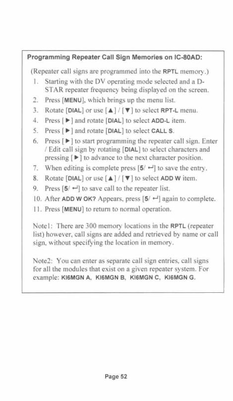
Programming Repeater Call Sign Memories on IC-SOAD:
(Repeater call signs are programmed into the RPTL memory.)
I. Starting with the DV operating mode selected and a 0-STAR repeater frequency being displayed on the screen .
2 . Press [MENU], which brings up the menu list.
3. Rotate [DIAL] or use [.. ] / [T] to select RPT-L menu.
4. Press [ ~] and rotate [DIAL] to select ADD- L item .
5. Press [ ~] and rotate [DIAL] to select CALL S.
6. Press [ ~ ] to start programming the repeater call sign. Enter/ Edit call sign by rotating [DIAL] to select characters andpressing [ ~ ] to advance to the next character position.
7. When editing is complete press [5/ .-J] to save the entry.
8. Rotate [DIAL] or use [.. ] / [T] to select ADD W item.
9. Press [5/ +-1] to save call to the repeater list.
10. After ADD W OK? Appears, press [5/ +-1] again to complete.
11. Press [MENU] to return to normal operation.
Notel : There are 300 memory locations in the RPTL (repeaterlist) however, ca ll signs are added and retrieved by name or callsig n, without specifying the location in memory.
Note2: You can enter as separate call sign entries, call signsfor all the modules that exist on a given repeater system. Forexample: KI6MGN A, KI6MGN S, KI6MGN C, KI6MGN G.
Page 52

Programming MY and UR Call Sign Memories on ID-880H:
(See following box for repeater, RPT1 and RPT2 programming)
I . Starting with the DV operating mode selected and a D-STAR repea ter frequency being displayed on the screen.
2. Press [MENU], which brings up the menu list.
3. Rotate [DIAL] to select CALL-S menu.
4. Press [ ~] and rotate [DIAL] to select MY call sign memory.
5. Press [ ~ ] and rotate [DIAL] to select one of MY1 - MY1.
6. Press [ ~] to start programming the call sign .
7. Enter / Edit call sign by rotating [DIAL] to select charactersand pressing [ ~ ] to advance to the next character position.
8. When MY call editing is complete, press [.-J] to save .
9. Rotate [DIAL] to select the UR call sign memory.
10. Rotate [DIAL] to select an empty memory location, or aprogrammed ca ll sign you wish to overwrite: U01 - U60 .
I I . Press [ ~] to start programming the call sign .
12. Enter / Edit call sign by rotating [DIAL] to select charactersand pressing [ ~ ] to advance to the next character position .
13. When UR call editing is complete, press [.-J] to save .
14. Press [MENU] to return to normal operation.
Note: When programm ing your own call sign , MY, you can adda four charac ter note following the " / "symbol. Refer to thefollow ing sectio n.
Page 53

Programming Repeater Call Sign Memories on ID-880H:
(Repeater call signs are programmed into the RPTL memory.)
I . Starting with the DV operating mode selected and a 0 -STAR repeater frequency being displayed on the screen.
2. Press [MENU], which brings up the menu list.
3. Rotate [DIAL] to select RPT-L menu.
4. Press [ ~] and rotate [DIAL] to select ADD-L item.
5. Press [ ~] and rotate [DIAL] to select CALL S.
6. Press [ ~ ] to start programming the repeater call sign . Enter/ Edit ca ll sign by rotating [DIAL] to select characters andpressi ng [ ~ ] to advance to the next character position .
7. When editing is complete press [ ...-J] to save the entry.
8. Rotate [DIAL] to select ADD W item.
9. Press [ ...-J] to save call to the repeater list.
10. After ADD W OK? Appears, press [ ...-J] again to complete.
II. Press [MENU] to return to normal operation.
Notel: There are 300 memory locations in the RPTL (repeaterlist), however, call signs are added and retrieved by name orcall sign, without specifying the location in memory.
Note2: You can enter as separate call sign entries, call signsfor all the modules that exist on a given repeater system. Forexample: KI6MGN A, KI6MGN S, KI6MGN C, KI6MGN G.
Page 54

Programming Call Sign Memories on IC-91AD and IC-92AD:
I . Starting with the DV operating mode selected and a D-STA R repeater frequency being displayed on the screen.
2. Press [MENU], which brings up the menu list.
3. Rotate [DIAL] or use [.A.] / [ 'Y] to select CAL L SIGN entry.
4. Press [ ~] to access the CALL SIGN Routing Registerdisplay.
S. Rotate [DIAL] or use [.A.] / [ 'Y] to select the associated callsign fie ld for memory you wish to edit : UR, R1, R2, or MY.
6. Press [ ~] to enter the selected field's memory bank .
7. Rotate [DIAL] or use [ .A.] / [ 'Y] to select an empty memorylocation , or a programmed call sign you wish to overwrite.
8. Press [ ~] to start programming the call sign .
9. Use the keys as described at bottom of the screen to enterthe des ired ca ll sign .
10. When editing is complete, press [5/ ...-J] to save call sign .
Note : When programming your own call sign, MY, you can adda four character note following the " / " symbol. Refer to thefollowing section.
Page 55

Programming Call Sign Memories on the IC-2820
I. Starting with the DV operating mode selected.
2. Press [F] to access the function keys
3. Press [MENU] to select the MENU screen .
4. Rotate [MAIN- BAND] to select CALL SIGN MEMORY.
5. Press [MAIN- BAND] and then rotate [MAIN- BAND] to selectthe call sign memory you wish to modify:
a) YOUR CALL SIGN MEMORY
b) RPT CALL SIGN MEMORY
c) MY CALL SIGN MEMORY
6. Press [MAIN- BAND] and then rotate [MAIN- BAND] to selecta call sign you want to edit , or an empty memory channelyou wish to program.
7. Press [MAIN- BAND] to start editing. Use the key functionsat the bottom of screen to enter or edit the call sign .
a) Press [ABC] to select between lower and upper caseb) Press [12/] to select between numbers and symbolsc) Rotate [MAIN- BAND] to select charactersd) Use [<] and [>] keys to move entry position cursore) Press [CLR] to clear selected charactersf) Press [CLR] I sec to clear all characters after the cursorg) Press [GW] to tum the gateway setting on and off.
8. Press [MAIN- BAND] to save the programmed call sign .
9. To exit the CALL SIGN MEMORY screen and return tonorma l operation, press [BACK] as required.
Note: When programming your own call sign , MY, you can adda four character note following the " / " symbol. Refer to thefollowing section for suggestions on using the note .
Page 56

Programming Your Own Call SignUse the preceding procedure to program your own call into the MyCall Sign Memory, which has space for saving up to six call signvariations. If you "registered" any call sign variations when youregistered for gateway usage, you may want to program those samevariations into the My Call Sign Memory bank.
In addition to programming your call sign , you also have the option ofprogramming a four-character "note" which will appear after yourcall sign . When your call sign is displayed on a receiving station 'sradio, it is followed by the" / " symbol and your four-character note .
As it is only used for informational purposes, this note is free form; itcan be anything you wish to communicate. The catch is that its onlyfour characters long. A lot of hams use it to indicate the model ofradio they are using: IC80 , IC91 , IC92, 2820 and so on. Others, withshort names enter their name: Bob, John , Eric, etc . Use yourimagination; maybe you can come up with something unusual. Ofcourse, you also have the option of leaving it blank.
Page 57

Recalling Call Sign Fields from a Frequency MemoryThree of the Call Sign Routing Register fields ( UrCa ll, RPT1 andRPT2 ) can be set as a group when recalling a memory channel wh ichhas been programmed with a DV mode repeater frequency . Forrepeaters that you intend to operate on, this is by far the best methodto use. Once programmed, operation is simple, you just recall thedesired repeater frequency from memory and everything isautomatically set.
Programming a memory channel with a DV mode repeater frequencyis no differen t than programming a conventional repeater frequency tomemory. Just as with conventional repeater frequency programming,the repeater frequency, mode of operation, in this case DV mode , thepower level, and repeater offset are all saved to memory. In DVmode however, the current UrCall , RPT1 and RPT2 fields of the CallSign Routing Register are also saved to memory. By setting the callsign fields as required for the desired repeater mode of operation,before saving the frequency setup to memory, it is all saved at thesame time to a single memory channel.
With a little thought and planning you can get quite clever with this .All the D-STAR modes that you might use on different repeaters canbe programmed in advance. Indeed, many local repeater groups canprovide you with a "cheat sheet" containing all the standardcomb inations you might use with their repeaters. Some groups, oryour local ham supply store , might be able to either "clone" yourradio, or give you a file that can be loaded from a PC with all thestandard freq uencies and modes already setup . If a file is providedfor use with radio programming software, it will be radio spec ific, soyou will need a version of the file that is for your particular radiomodel.
Organizing D-STAR Repeater Calling Modes in MemoryIf you are going to program and organize your own DV modememory channels, it may be instructive to see how the PAPA systemorganizes radio memories for accessing their system of D-STARrepeaters. In Southern California we are fortunate to have the PAPArepeater system. With its network of six different D-STAR repeater
Page 58

systems, it provides wide-area coverage over several differentcounties. With the large number of repeaters in their system, theyhave worked out a fairly nice system for programming their user'sradios.
The PAPA system administrators provide their users with an Ieomcompatible data file for programming their radios with a standardizedset of repeater access configurations. Because of differences in theradios provided by Ieom, different .icf formatted files must be usedfor each model of radio. The IC-80, IC-91, IC-92, IC-800, IC-2820etc, all require different .icf files. The PAPA system administratorshave a number of different .icf files , called "Code Plugs" to supportdifferent radios.
In addition to providing the programs in the Ieom .icf file format thatcan be downloaded to the radio using Icom 's RS programmingsoftware, they also provide an Excel spreadsheet compatible .csv fileformat (comma separated value). Using the .csv format, users can notonly print out and examine how repeaters are accessed either locallyor via gateways, but with a little work can convert the data to becompatible with other radios or software programs.
If you have access to an .icf file from one radio and want to convertthe file to be compatible with a different model radio, a handyconversion program called Ir-Startlom is located athttp://dstarcom.ae7q.netiFull instructions and explanation of the fileformat is also found at the same URL.
At the time this is being written, the standard PAPA system CodePlug contains 79 entries, which go into 79 consecutive frequencymemories in the radio. Rather than show all the file entries the PAPAsystem uses for programming memory channels, the principle of howits organized can be understood by examining just the Call SignRouting Register variations that are used to implement various 0STAR system access modes from one local repeater system.
The PAPA system identifies its different O-STAR repeater systemsusing "0" numbers. The numbers range from D I to 016 with somegaps in the numbering sequence.
Page 59

The chart below illustrates Call Sign Routing Register variations forimplementing local repeater operation, echo testing, info request, andseveral repeater node call configurations to other repeaters within thePAPA system. The comments describe the O-STAR calling / routingmethods used when operating from local modules Band C of the 0 I0repeater. Using this as an example, you can easily create similarconfigurations for operating on your local system.
Name UrCali RPT1 RPT2 c omment010B CO COCOCO KI6MGN B KI6MGN G Local 0 eration on module B, with oatewav enabled010B ECHO KI6MGN E KI6MGN B KI6MGN G Audio echo test on module B010B INFO KI6MGN I KI6MGN B KI6MGN G Link status request. module B010B > 01 IKI6JKAB KI6MGN B KI6MGN G Repeater node call to KI6JKA module B010B> 04 IKF6BOKB KI6MGN B KI6MGN G Repeater node call to KF6BOK module B010B>11A IKW6HROA KI6MGN B KI6MGN G Repeater node call to KW6HRO module A010B >11B IKW6HROB KI6MGN B KI6MGN G Repeater node call to KW6HRO module B010B >15B IKI6KOUB KI6MGN B KI6MGN G Repeater node call to KI6KOU module B010B >010C IKI6MGN C KI6MGN B KI6MGN G Repeater node call to module C of the local repeater010C CO COCOCO KI6MGN C KI6MGN G Local operation on module C, with gateway enabled010C ECHO KI6MGN E KI6MGN C KI6MGN G Audio echo test on module C010C INFO KI6MGN I KI6MGNC KI6MGN G Link status request , module C010C> 01 IKI6JKAB KI6MGN C KI6MGN G Repeater node call to KI6JKA module B010C > 04 IKF6BOKB KI6MGN C KI6MGN G Repeater node call to KF6BOK module B010C>11A IKW6HROA KI6MGN C KI6MGN G Repeater node call to KW6HRO module A010C>11B IKW6HROB KI6MGN C KI6MGN G Repeater node call to KW6HRO module B010C>15B IKI6KOUB KI6MGN C KI6MGN G Repeater node call to KI6KOU module B
Note that the Name column in the above chart is the name that isprogrammed in the memory cha nnel. These are the names that willbe displayed on the radio's LCD when performing memory recalloperations. The names chosen should help you recall what theindivid ual memory channels are used for. In the case of the PAPAsystem repeaters, you can see that the "Dnn" designations combinedwith the > symbol indicate the operation to be performed and whichrepeater modu les are involved.
Whe n creating your own set of repeater access memories, by using asimi lar format you could add node routing to distant repeaters,simulcast and multicast operation, and even repeater and reflectorlinking operations. Operating different O-STAR modes is greatlysimp lified when your favorite repeaters and O-STAR modes ofoperation are saved to memory . Another big plus , once you haveverified that they work, they can eliminate errors that otherwise areprone to hap pen when programming things onthe fly.
Page 60

Received Call HistoryAs ca lls are received, the radio saves the call signs being used by thestation mak ing the call in the Received Call memory. This memoryhas the capac ity for storing 20 of the most recently received calls,num bered RX01 through RX20, with RX01 being the most recent. Asnew calls are received, older ones are pushed off the bottom(discarded) since they wou ld be numbered beyond RX20.
If you need to double-check the call sign of a recent call , the ReceivedCall memory can be quite useful. Many times you may only partiallyhear a person's call sign , or have trouble understanding what theperson said . Th is is especially true when making contacts withforeign countries, where to our ears the person has an accent, whichmay make it difficult to clearly understand what was said. Bycheck ing the Received Call memory we can see what the call was .
Examining Calls in the Received Call Memory
The Received Call memory stores the person 's call sign , the CALLER,and also the RPT1 and RPT2 call signs that were used .
Examining Received Call Memory on the IC-91AD andIC-92AD:
I. Starting with the DV operating mode selected and a DSTA R repeater frequency being displayed on the screen.
2. Press [MENU], which brings up the menu list.
3. Rotate [DIAL] or use [.] / [T] to select RX CALL S entry.(On the IC-80AD select RX CAL)
4. Press [ ~] to ente r the Received Cal l Memory. You willsee the RX01 memory number and the call sign of the mostrecently received call, the CALLER.
5. Rotate [DIAL] or use [.] / [T] to select a call record.
6. Press [ ~ ] and then rotate [DIAL] or use [.] / [T] to viewthe station 's CALLER, RXRPT1 and RXRPT2 call signs.
7. After examining the call signs , press [MENU] to exit thememory record and return to normal operation .
Page 61

Examining the Received Call Memory on the IC-80ADand ID-880H
1. Starting with the DV operating mode selected .
2. Press [MENU], which brings up the menu selection mode.
3. Rotate [DIAL] or use [...] / [T] to select RX CALL S entry.
4. Press [ ~] to enter the Received Call Memory. You willsee the 01 memory number and the call sign of the mostrecently received call, the CALLER.
S. Rotate [DIAL] or use [...] / [T] to view other call records.
6. To view the station 's CALLERs NOTE, RXRPT1 and RXRPT2call signs, repeatedly press [ +-.lj as required.
7. After examining the call signs, press [MENU] to exit thememory record and return to normal operation.
Examining the Received Call Memory on the IC-2820
I . Starting with the DV operating mode selected .
2. Press [F] twice to access the DV mode function keys:(CS CD CQ R>CS etc.)
3. Press [CD] to display the RX CALL SIGN screen. You willsee the RX01 memory number and the call sign of the mostrecently received call, the CALLER.
4. Rotate [MAIN- BAND] to select a call record : RX-01 ~ RX·20.
5. Press [MAIN- BAND] to view the record's CALLER, CALLEDand RXRPT1 and RXRPT2 call signs.
6. To exit or view another record press [BACK].
7. After examining and making note of the call signs, press[BACK] as required to exit and return to normal operation .
Page 62
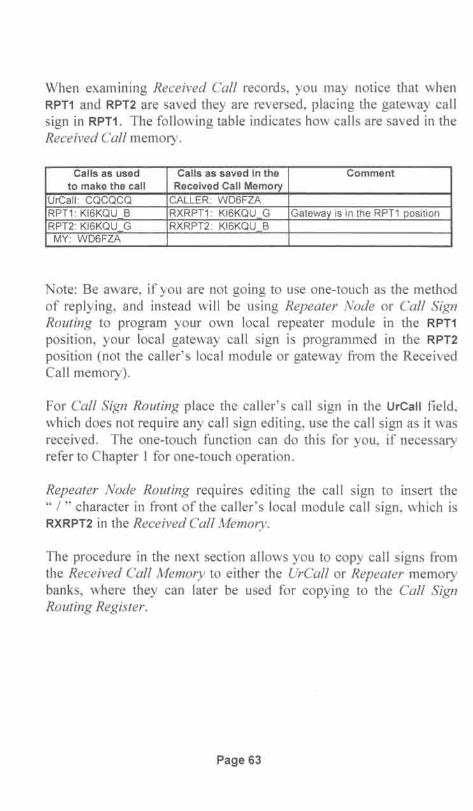
When examining Received Cal! records, you may notice that whenRPT1 and RPT2 are saved they are reversed, placing the gateway callsign in RPT1. The following table indicates how calls are saved in theReceived Cal! memory.
Calls as used Calls as saved in the Commentto make the call Received Call Memory
UrCall: CQCQCQ CALLER: WD6FZARPT1: KI6KQU B RXRPT1: KI6KQU G Gateway is in the RPT1 positionRPT2: KI6KQU G RXRPT2: KI6KQU BMY: WD6FZA
Note: Be aware, if you are not going to use one-touch as the methodof rep lying, and instead will be using Repeater Node or Cal! SignRouting to program your own local repeater module in the RPT1
position, your loca l gateway call sign is programmed in the RPT2
position (not the caller's local module or gateway from the ReceivedCall memory) .
For Cal! Sign Routing place the caller's call sign in the UrCall field,which does not require any call sign editing, use the call sign as it wasreceived. The one-touch funct ion can do this for you, if necessaryrefer to Chapter 1 for one-touch operation.
Repeater Node Routing requires editing the call sign to insert the" / " character in front of the caller's local module call sign , which isRXRPT2 in the Received Cal! Memory.
The procedure in the next section allows you to copy call signs fromthe Received Cal! Memory to either the UrCal! or Repeater memorybanks, where they can later be used for copying to the Cal! SignRouting Register.
Page 63

Copying Calls from the Received Call Memory
If desired, you can copy calls that were automatically recorded in thetempo rary Received Cal! Memory to either the UrCal! or RepeaterMemory banks. This can be useful if you heard a call that you wantto save for later use .
Copying Calls from the Received Call Memory on the IC-80ADand ID-880H:
1. Starting with the DV operating mode selected and a 0-STAR repeater frequency being displayed on the screen.
2. Press [MENU] , which brings up the menu selection mode.
3. Rotate [DIAL] to select the RX CAL entry.
4 . Press [ ~ ] to access the received call memory bank.
5. Rotate [DIAL] or use [.A] I [T] to select the call record youwant to copy from, numbered 01 through 20.
6. Repeatedly press [ ...-J] to select the call sign you wish tocopy, either: CALLER, RXRPT1 or RXRPT2.
7. Press [ ~] to enter the copy mode.
8. Rotate [DIAL] or use [.A] I [T] and select one of thefollowing to specify the memory channel to be programmed.
• C ALL Copies Caller to UR, and RPT1/RPT2 to RPTL list• C Urxx Copies Ca ller to selected UR channel 1-60.• C R-L Copies RPT1/RPT2 to the RPTL repeater list.• CLEAR Clears selected record from Rx Call Memory.
9. Press [ ...-J] to complete the copy or clearing operation.
10. Press [MENU] to exit and return to normal operation.
Page 64

Copying Calls from the Received Call Memory on the IC-91ADand IC-92AD:
I . Starting with the DV operating mode selected and a 0-STA R repeater frequency being displayed on the screen.
2. Press [MENU], which brings up the menu list.
3. Rotate [DIAL] to select the RX CALL S entry .
4. Press [ ~ ] to access the RX CALL SIGN memory bank.
5. Rotate [DIAL] or use [ ... ] / [T] to select the call record youwant to copy from , numbered RX01 through RX20 .
6. Press [ ~] and then rotate [DIAL] to skip over ALL and selectthe call sign you wis h to copy, either: CALLER, RXRPT1 orRXRPT2.
7. Press [ ~] to enter the copy mode.
8. Rotate [DIAL] or use [ ... ] / [T] to select the LIST SEL entry tobe able to select the memory channel to be programmed.
9. Press [ ~] and then select the memory location you wish tocopy into. (Select an empty channel or over write aprogrammed channel as desired .)
10. Press [ ~] to save to the selected location.
II. Press [MENU] to exit and return to normal operation.
Page 65
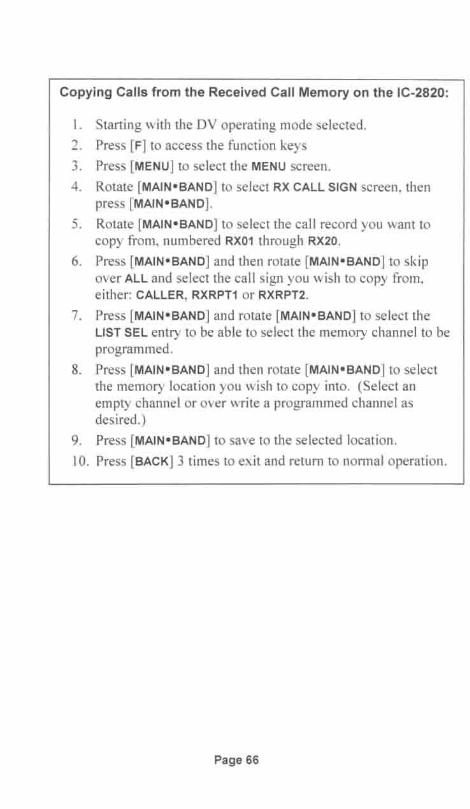
Copying Calls from the Received Call Memory on the IC-2820:
1. Starting with the DV operating mode selected.
2. Press [F] to access the function keys
3. Press [MENU] to select the MENU screen.
4. Rotate [MAIN- SAND] to select RX CALL SIGN screen, thenpress [MAIN- SAND].
5. Rotate [MAIN- SAND] to select the call record you want tocopy from, numbered RX01 through RX20.
6. Press [MAIN- SAND] and then rotate [MAIN- SAND] to skipove r ALL and select the call sign you wish to copy from ,either: CALLER , RXRPT1 or RXRPT2 .
7. Press [MAIN- SAND] and rotate [MAIN- SAND] to select theLIST SEL entry to be able to select the memory channel to beprogrammed.
8. Press [MAIN- SAND] and then rotate [MAIN- SAND] to selectthe memory location you wish to copy into. (Select anempty channel or over write a programmed channel asdesired.)
9. Press [MAIN- SAND] to save to the selected location .
10. Press [SACK] 3 times to exit and return to normal operation.
Page 66

Chapter 5: DV Short Text Messaging
You can configure your transceiver to send a short message wheneveryou transmit. These messages are transmitted along with your voiceevery time you transmit, and will show up in the RX Message bufferof other user's radios. Typically up to five messages, each amaximum of 20 characters in length , can be programmed into theradio . Before transmitting you select which one of the five you wishto transmit.
The messages are free form and can be used to convey a variety ofinformation. It's too bad they are only 20 characters long, as it can bea challenge to figure out how to fit what you want to say using only20 characters.
Some common uses:• Radio configuration• Your name and location• Your full name (first and last)• Special announcements• Radio settings to use for answering your call• Reflector you are using• Your web page or email address
Providing instructions on how users should set their radio to make areturn call back to you is an interesting use for short status messaging.I found several Japanese stations using this technique. Their shortstatus messages were formatted similar to this : "Set Ur to /JP 1XXX,"and I've seen others with the message "Use One Touch Button."Even if you don 't use this technique yourself, it's worth rememberingif you hear a call and are unsure of how to call back. They might betelling you via short messaging.
Programming DV Short MessagesProgramming messages into the radio is relatively straightforward.I like using lower-case characters to help make run together words orabbreviations understandable without having to insert a space. For
Page 67

instance, here is what I have programmed in one of my memories:"Bernie SanDiego NoCo". This comes to exactly 20 characters andwould not have fit had I used spaces. NoCo stands for North Countyand may not be obvious, but SanDiego is quite understandable.
Unfortunately there is a drawback to using lower-case characters.Radios such as the IC-80AD, ID-800H, ID-880H, and IC-V82 canon ly disp lay upper-case characters, so a message received on thoseradios may not disp lay as intended.
Programming and Transmitting Short Messages on thele-80AD and ID-880H:
1. Starti ng with the DV operating mode selected and a D-STA R repeater freq uency being disp layed on the screen.
2. Press [MENU] to bring up the menu selection mode .
3. Rotate [DIAL] or use [.. ] / [T] to select MESSAG.
4. Press [ ~] and rotate [DIAL] to select TX MSG.
5. Press [ ~] to enter the message entry / editing screen.
6. Rotate [DIAL] or use [.. ] / [T] to select one of the fivememory channels TM1-TM5 or OFF. (Note: OFF is used todisab le message transmissions.)
7. Press [ ~] to start programming the message . Enter / Edityour message by rotating [DIAL] to select characters andpressing [ ~ ] to advance to the next character position.
8. When editing is complete, press [ ...-J] to save the message .
9. Before returning to normal operation, rotate [DIAL] or use[.. ] / [T] to select the message memory, TM1-TM5 you wishto transmit, or select OFF if you wish to disable messagetransmission .
10. Press [~ ] to return to the TX MSG screen.
1I . Press [MENU] to exit and return to nonnal operation.
Note: If enabled, the message is transm itted every timeyou press [PTT].
Page 68

Programming and Transmitting Short Messages on theIC-91AD and IC-92AD:
I. Starting with the DV operating mode selected and a 0-STAR repeater frequency being displayed on the screen.
2. Press [MENU] , which brings up the menu list.
3. Rotate [DIAL] or use [o6] / [T] to select MESSAGE I POS.
4. Press [ ~] to acce ss the MESSAGE I POSITION screen.
5. Rotate [DIAL] or use [o6] / [T] to select TX MESSAGE .
6. Press [ ~] to go to the TX MESSAGE editing screen.
7. Rotate [DIAL] or use [o6] / [T] to select one of the fivememory channels Ch01-Ch05 or OFF. (Note : OFF is used todisable message tran smission s.)
8. Press [ ~ ] to start programming your message.
9. Use the keys as described at bottom of the screen to enteryour message text.
10. When editing is complete, press [5/ o-J] to save the messageand return to the TX MESSAGE screen.
II . Before returning to normal operation, rotate [DIAL] or use[o6] / [T] to select the message channel Ch01-Ch05 youwish to transmit, or select OFF if you wish to disablemessage transmission.
12. Press [MENU] to exit and return to normal operation.
Note: If enabled, the message is transmitted every timeyou press [PH].
Page 69

Programming Short Messages on the IC-2820:
I . Starting with the DV operating mode selected.
2. Press [F] to access the function keys
3. Press [MENU] to select the MENU screen.
4. Rotate [MAIN- BAND] to select DV MESSAGE screen, thenpress [MAIN- BAND].
5. Rotate [MAIN- BAND] to select TX MESSAGE MEMORY.
6. Press [MAIN- BAND] and then rotate [MAIN- BAND] to selectone of the five TX memory channels 01-05.
7. Press [MAIN- BAND] to start programming your message.
8. Use the key functio ns at the bottom of screen to enter or edityour message.
a) Press [ABC] to select between lower and upper caseb) Press [1/] to select between numbers and symbolsc) Rotate [MAIN- BAND] to select charactersd) Use [<] and [>] keys to move entry position cursore) Press [CLR] to clear se lected charactersf) Press [CLR] I sec to clear all characters after the cursor
9. When message is complete, press [MAIN- BAND] to save it.
10. To exit the TX MESSAGE MEMORY screen and return tonormal operation, press [BACK] as required.
Transmitting Short Messages on the IC-2820:
I. Starting with the DV operating mode selected.
2. Press [F] to access the funct ion keys
3. Press [MSG] to select the MESSAGE screen.
4. Rotate [MAIN- BAND] to select TX MESSAGE screen, thenpress [MAIN- BAND].
5. Rotate [MAIN- BAND] to select the channel to be transmittedCh01 - CH05, or select OFF to disab le message transmission.
6. Press [BACK] as required to return to normal operation.
Note: If enabled, the message is transmitted every time youpress [PH] .
Page 70

Reviewing Received Short MessagesOnly the last message received can be viewed. This can present aprob lem, because it can be overwritten if another message happens toarrive before you have a chance to view the message.
Reviewing Received Short Messages on the IC-80AD and1D-880H:
I . Starting with the DV operating mode selected and a 0-STA R repeater frequency being displayed on the screen.
2. Press [MENU] to bring up the menu selection mode .
3. Rotate [DIAL] or use [ A] / [ T] to select MESSAG .
4. Press [ ~] and rotate [DIAL] to select RX MSG.
5. Repeatedly press [+oJ] to view whole received message.
6. Press [MENU] to exit and return to normal operation.
Reviewing Received Short Messages on the IC-91AD andIC-92AD:
I. Starting with the DV operating mode selected and a 0-STAR repeater frequency being displayed on the screen.
2. Press [MENU], which brings up the menu list.
3. Rotate [DIAL] or use [ A] / [T] to select MESSAGE I POS.
4. Press [ ~ ] to access the MESSAGE I POSITION screen.
5. Rotate [DIAL] or use [ A] / [T] to select the RX MESSAGE .
6. Press [ ~] to view the RX MESSAGE screen .
7. Rotate [DIAL] or use [ A] / [T] to toggle between viewingthe received MESSAGE or the CALLER ' s call sign .
8. Press [5/ .-J] to return to the RX MESSAGE screen.
9. Press [MENU] to exit and return to normal operation.
Page 71

Reviewing Received Status Messages on the IC-2820:
1. Starting with the DV operating mode selected.
2. Press [F] to access the function keys
3. Press [MENU] to select the MENU screen.
4. Rotate [MAIN- SAND] to select DV MESSAGE screen, thenpress [MAIN- SAND].
5. Rotate [MAIN- SAND] to select RX MESSAGE.
6. Press [MAIN- SAND] to view the RX MESSAGE screen .
7. Press [SACK] 3 times to exit and return to normal operation.
Page 72

Chapter 6: Internet Resources
Amateur radio is fortunate to have enterprising programmers whomhave authored a number of innovative and useful D-STAR web pageprograms. Lets examine a couple of the most popular ones: D-STARCalculator andjFindu.
D-STAR Routing and Linking Calculator
To assist amateurs with programming the call routing parameters fortheir radios, Ed Woodrich, WA4YIH has developed an easy to useprogram, D-STAR Calculator. The program operates on-line via theInternet and uses pull -down menus to make repeater and routingse lections.
You start out by se lecting the local repeater and module that you areusing to get to the gateway. Next you select the D-STAR call routingmode that wi ll be used to route the cal l. Finally the remote repeatermodu le you want your signal to come out of is selected. After all thisinformation has been selected, the calculator displays the settings youneed to program into your radio for making the call.
This program really simplifies finding repeaters and programming theCall Sign Routing Register; anybody can do it!
Operating the D-STAR Calculator ProgramThis program contains a full list of repeaters and reflectors that areavailable for use worldwide. US repeaters are listed by state and city .If you want to make a ca ll to a foreign country, a pull-down listmakes it easy to determine which repeaters are available by country,province and city.
D-STAR Calculator can be found at the following URL:http://www.dstarinfo.com/Calculator/
Page 73

In the sample screen shot below, after I selected my local repeaterusing the Source Repeater pull-down menu, the program displayed alist of repeater modules that are available on the selected repeater. Inthis case there was only one Source Module displayed, so I selected it.
SourceModul e
Function Source Route " ,
Destination Local Repeater
R tLocal Repeater with Galewav
epea er Echo Test .Re eaterStatus
Destination • . • • .Module SpecificUser
link to Repeaterlink to ReflectorUnlink Repeater
l!::!Jgh-SEeed~_ _ _.J
As shown above, I then selected the D-STAR routing / linkingFunction that I wanted to use from a list of available functions. Thelist includes all the routing and linking modes that were discussed inChapters I and 2 plus one more, High-Speed Data. In this example Iselected Source Route as the mode of routing I wanted to use.
Page 74

Continuing with making selections, as in the screen shot below, Iselected Canada, Calgary VE6WRN, as my Destination Repeater andmodule B as my Destination Module, which are the last pieces ofinformation needed by the calculator.
D-STAR Calculator2.1.2.0
DDA 1247.5000 RPSDV A 1287 5000-20 0000
IIII
DV C 146.8050 -a 6000
After selecting the Destination Module, the calculator came up withthe results shown in the following screen shot. The shaded boxcontains the information needed to program your radio's Call SignRouting Register fields: UrCall, RPT1 and RPT2. If you need it, thefrequency and offset for your local repeater are also shown.
Page 75

Below the shaded box, the program displays a call routing diagram.At the sides and bottom are sample scripts suggesting how to identifywhen making the ca ll. Besides giving their location and the repeatermodu le they are using, the scripts show the two ham s exchangingrepeater frequency and offset information. Typically when operatingon D-STAR, exchanging repeater frequencies is unnecessary.
Programming for talkingOn K16KQti (port DV B) to\ 'E6WR,'-; (port DV B)
YOtiR:: /VE6WRNB
RPT1:KI 6KQU a aRPT2:KI 6KQU a G
S Radi T 44i.8400 ~IHz Offset ·et 0 0 : 5.0000 ~lHz
' ,' represents a spaceHelp!
I'm nearSan DiegoCA l"SA.I'm talking
on
CQ CQ CQ This is (your callsign)listening on the San Diego repeater ,
KI6KQ\.: (port D\ ' B)
I'm near~Ga:""'Y Calgary .
~~Coot1oller ~~Italking
~lland ModUIe \'E6WR.~
l...t/( (port D\·~ B) and my
" radio is set
~8. ~~49~ 50/ \ - > 0000
,
Say Howdy!
As you can see , the program is simple to use and by making a few listdriven selections you are provided with all the parameters necessaryfor programming your radio to make the call.
Page 76
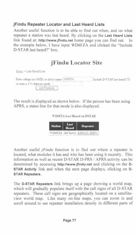
jFindu Repeater Locator and Last Heard Lists
Another useful function is to be ab le to find out when, and on whatrepeater a station was last heard . By clicking on the Last Heard Listslink found at: http ://www.jfindu.net home page you can find out. Inthe example below, I have input WD6FZA and clicked the " IncludeD-STAR last heard?" box .
jFindu Locator SiteHome> Last Heard Lists
Enter callsign (no SSiD) or object .:n:ar:: :n...e::.: _,==="c"c=.~
or enter a :3 -8 character prd ix: [
I List Posit ions I
..... ---I Include D-STAR last heard' Gj
.'J
The result is displayed as shown below. If the person has been usingAP RS, a status line for that mode is also displayed.
WD 6FlA Last Heard on DSTAR••-IWD6FZA 3h4'7m~3 s Kl6KQCB(D\ i !
Another useful jFindu function is to find out where a repeater islocated, what modules it has and who has been using it recently. Thisinformation as well as recent D-STAR D-PRS / APRS activity can bedetermined by accessing http ://www.jfindu.net and clicking on the DSTAR Activity link and when the next page displays, clicking on DSTAR Repeaters .
The D-STAR Repeaters link brings up a page showing a world map,which will gradually populate itse lf with the call signs of all D-STARrepeaters. These call signs are geographically located on a satelliteview world map. Like many on-line maps, you can zoom in andscroll aro und to see repeater installation density in different parts of
Page 77
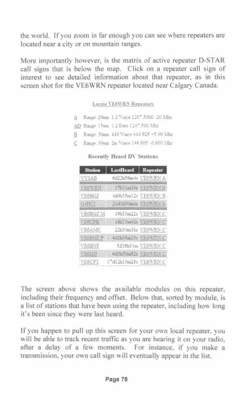
the world. If you zoom in far enough you can see where repeaters arelocated near a city or on mountain range s.
More importantly however, is the matrix of active repeater D-STARcall signs that is below the map . Click on a repeater call sign ofinterest to see detailed information about that repeater, as in thisscreen shot for the VE6WRN repeater located near Calgary Canada.
Locale YE6WRS Repeaters
A Range: 20mn 1.2 Voice 128i .5000 -20 Mhz
AD Range: 15mn 1.2 Data 12r.500 ).oll,z
~ Range: 30nm -i-i0 Voice-i-i-i.925 -5.00 Mhz
~ Range: 30nm 2m Voice 146.805 -0.600 Mhz
Recently Heard DY Stations
6d22h56m-is \'t:6WRi', AiIVE6\\'Rl~
\"E6BGZ
G-iHCI
GZ:\1
K
V"E6A.\IC
r 'E6BGZ P
\'E6BXF
!VE6DJJ
.\ 'E6CPT
lih31m3-is \'E6\\'P-N ~
4d-ih35m12s \ 'E6WR.,\ B '
21dlh50m-fs \ 'E6WRN B
19h13m22s \ "E6\\'Rl';"
19h13m-i2s~~~~l
22h30m3Ss \ "E6\\'Rl,;" C
4dlh-f8m13s \ 'E6\v""P-N C
5d16h31m \ "E6WR.,\ C
6d3h50m52s \ 'E6\\ 'P-N Ql1id12h13m2Ss \"E6\VR.'\C!
The screen above shows the available modules on this repeater,including their frequency and offset. Below that , sorted by module, isa list of stations that have been using the repeater, including how longit's been since they were last heard.
If you happen to pull up this screen for your own local repeater, youwill be able to track recent traffic as you are hearing it on your radio ,after a delay of a few moments. For instance, if you make atransmission, your own call sign will eventually appear in the list.
Page 78

Page 79

D-STAR Users.org Last Heard ListThe D-STAR users .org web site has a very useful tool that lists allstations recently heard on the D-STAR network, an example of whichis shown on the facing page .
Found at http://dstarusers.org/lastheard.php the tool provides a timestamped history of the call sign of the station making the call, therepeater node that he is using and its location. Very useful for seeingwhere there is traffic that you might want to listen to and perhapsmake a contact with.
The listings shown on the page will automatically update every fewminutes, providing a "close to" real time history of what is happeninganywhere in the worldwide D-STAR network.
By clicking on the header, the list can be sorted by Callsign, TimeHeard or by the Reporting Node.
Page 80

"'CDI
ICC1lco....
PU2TRG
PU4DNP
AEOM.W
K4HC
KA9SCf
WB9JPH
Kf 5DOP
AJ4BT
WB9W LS
AJ4G
LU1f KR
EI8DJ
PY4HC
VA21Nf
IZOGQT
11 / 23109 23:39:28 UTC
11 123/ 09 23:39:27 UTC
11 123/ 09 23:39:27 UTC
11 123/09 23:39:20 UTC
11 123/ 09 23:39:15 UTC
11 123/ 09 23:39:11 UTC
11 123/09 23:39: 10 UTC
11 123/09 23:39:10 UTC
11 123/ 09 23:39:07 UTC
11123/ 09 23:38:59 UTC
111 23/ 09 23:38:48 UTC
11/23/ 09 23:38:32 UTC
l1 J23/09 23:38:30 UTC
11/23/ 09 23:38:28 UTC
11 123/ 09 23:37:47 UTC
PY2KCA C 2 M.et er s
LD4Vf Dongle User DVD
KOOIAN Dongle User DVD
W4GSO B 440 MHz
WA90 RC B 440 MHz
K9PAQ C 2 Met ers
W4LET B 440 MHz
W4GSO B 440 MHz
WA90 RC B 440 MHz
WA4VZY B 440 MHz
LU5f B C 2 Met ers
GB7CD C 2 Met ers DVD
PY4RCR C 2 Met ers
VA2RKB C 2 Met ers
IR5UBH B 440 MHz
Americana, Sao Paulo, Brazil
Orre , Norway
Des Moin es. lA, USA
Greensboro, NC, USA
Chicago, IL. USA
Richfield. WI, USA
NIEMPHIS, TN. USA
Greensboro , NC, USA
Chicag o, ILs USA
Middlesboro, Ken t ucky, USA
Rosari 0 , Santa Fe, Argen ti na
Cardiff, Wales, UK
Belo Hori zon t e, NIG, Brazil
Saint-Celixte, Quebec, Canada
Armata , Tuscany, It aly

NJ6N's Gateway Usage MonitorBrian Roode, NJ6N, who is also the author of d*Chat, has created acomprehensive tool for monitoring D-STAR activity that is occurringanywhere in the world. His D-STAR Usage Monitor , found athttp://nj6n.com/dplusmon/ summarizes call routing information forany transmissions going through the gateway system.
Using his tool, an example of which can be seen in screen shot on thefacing page, we can determine the following information about callsbeing made through the gateway system:
• Time and date that the call is being made ,• Cal l sign of the reporting / originating gateway,• Location of the originating gateway,• The call (MyCall and "/note") of the originating station,• The station 's DV Short Message, ifhe is transmitting one ,• How the station 's UrCall, RPTI & RPT2 call signs were set.
This information periodically updates, providing a history of activitythat has recently occurred. There can be a lag of several minutes ormore depending upon gateway and network loading, latency ofBrian's web server and your own web browser and other factors.
Notice that when a Reflector is being used, all gateways linked to thatReflector are shown . In the sample screen shot there is a long list ofgateways shown as being linked to reflector REFOO IC. While this isnot unusual for REFOO IC, D-STAR's Mega Repeater, the linkedgateway list for other reflectors is generally much shorter.
Clicking on the station's call sign, under the MyCali heading, accesseshis call sign information at the QRZ .com web page. Veryconvenient!
Likewise, clicking on a gateway 's Location will bring up thegateway's informational web page, providing the sponsoring grouphas one.
Page 82

2009-11-23 13:56:15Paciric K1HRO Salem, NH USAReflected To: K1HRO ( 1 )2009-11-1313:56:09 Pacific CQODLX Lisbon Portugal
2009,11-23 13:5605 Pacific REF001 C
CQCQCQ CQODLX B CQODLXG
CQCQCQ REF001 C WX-1GPB G
CQCQCQ REF001 G REFOO1 C
Myean ---WA1WOK H (iC92j CQCQCQ K1HROC K1HRO G
CT21UL (p)
Kl4SBT (ROB)Robert W Hoppe
MOMET (DNGL)
Locatio.
woovn \"E3RPT KES\\TB \\ ".1HFH KSLCD\\ '''LET \ "E3LSRWSSHl \\'DSAll WS:'-"Gl' \\l)-1STR \\' 2DGL KSBIG\ "E3R.\:RK2D!G:'-"J2DG WSBIKJ-1 L:'-"J KO:\IOG KOHA,\[ PY2KCAPY7DIG PY2KPP SZlS\' S\ "2FPY2KPEPY-1RCR \\ "$-1\'AKEi:\1\1 KF6R.~L K~RST K6ACS \YArrw \\ '6YYY:-"E-ISC\\ 'SSH\"KJ-I:\1:\1C WA6IRC\YX-1GPB WSR.,\;L \Y6DHS ( -11 )
Americana, Sao PauloBraZIlPY-lRCR W6DHS PY2KPE S\ '2F 52 IS\' PY2KPPPY-DlG\\ 'SR.'\;L wooxm \YSSH1 KE5\\"FB \\'DSAII KSLCD \\ 'SBI:'-"J2DG\\ 'X-1GPB K2DIGw 2DGL KSB1G WD-1STR \\'5:'-"GI;REF00 1 G \"E3RPT \"E3LSR W-lHFH KE-:\[\"J KF6R..-\L K6ACSWAiFW :-"E-1SC \\ '5SH\ ' \\ '''DOC WMIRC \\ 'S-1\'A W6YYYKOHA,\l KO:\IDG KJ.J:\[\1CK]-1L:'-"J W..LETK7RST
Reflected To:
Reflected To:
2009-11-23 13:55:-16 Pacific PY2KCA
DateMo. No.:3 13;55:34PST Z(I(W
-0III
10CDCOW

Page 84

Chapter 7: Radio Programming Software
If you are going to be programming a lot of repeater frequencies andD-STAR access call signs into your radio , you should definitelyconsider purchasing programming software for your radio. Not onlyis it much easier to do, you might be able to import programming filesfrom others that can significantly simplify setting up your radio.
Another plus for programming software is that once you have yourradio setup, a copy of your radio's frequency memories and setupmenus can be saved to your computer. This can be a lifesaver shouldyou need to reload your radio for any reason.
Besides the software itself, an interface cable for connecting betweenthe radio and your computer is required. Most of the time, a standardRS-232 PC serial port is used on the computer side . However, on theradio side , the connector is often unique to the radio. Frequently therequired cable comes with the purchase of the programming software.
Icom's Programming SoftwareIcom provides programming software (frequently called cloningsoftware) for their radios. The following list identifies the softwarepackages used with lcom' s D-STAR radios. Most of these come witha cab le, but some do not.
• IC-80AD CS-80/880 (free software download)
• IC-9IAD RS-91
• IC-92AD RS-92
• IC-V82 CS-V82
• IC-2820 CS-2820
• IC-2200 CS-2200
• IC-D800 CS-D800
• ID-880H CS-80/880 (free software download)
Page 85

RT System's Programming SoftwareRT-Systems also provides radio-programming software for radios ofall type s. Their software kits generally come with the required cable .Here are the RT part numbers for the software kits used with loom ' sD-STAR radios
• IC-80AD WCS -80
• IC-9IAD WCS -91
• IC-92AD WCS-92
• IC-2820 WCS-2820
• IC-2200 WCS-2200
• IC-D800 WCS-D800
• lD-880H WCS -D880
1 have not used any ofRT System ' s software for D-STAR radios, buthave used their programs for several conventional tran sceivers. Thesoftware I've used was reliab le and did the job . Their software isgeared towards programming your radio and doe s not include the"virtual radio" features discussed below.
Icom's RS-91 and RS-92 Programming SoftwareMost all programs provide similar programming functionality ; someof them go a step beyond. Here we will review the features of leom'sRS-92 (Remote Control) software application as an example of whatcan be done with one of the more enhanced programming packages.
Unlike most other programming software packages, the RS-91 andRS-92 software packages have the capability of actually controllingthe radio via a "virtual radio " looking screen. Using this "virtualradio" is quite simi lar to using a remote front panel ; the connectedradio responds just as if you were pushing directly on the radio 's frontpanel buttons. In general, radio -programming software packages donot have this "virtual radio" capability; it is limited to leom's RS,Remote Control series of software. leom 's CS series CloningSoftware is more typical of what is usually available for programmingradios .
Page 86

When the RS-92 program is started, it comes up with the "virtualradio" screen. The first thing you need to do is click on the Optionpull-down menu and select the PC COM port that you will be using.The program will read the radio's current settings, which takes aseco nd or two, then the "virtual screen " will display the sameinformation that is being displayed on the radio's screen. While thecom puter is reading the balance of your radio 's settings (ca lledsynchronizing), the 0 button near the top of the display wi ll be red;synchronization is complete when it turns black.
; ) Untitled - RS-92 I!lIiI£i
D-STAR
B 447. 840D15B>11AMID I1A]J066
To examine or edit the radio's memory, wait for the synchronizationto complete ( 0 button turns black) and cl ick on the View pull-downand select Edit Memory Channel and the Memory CH screen pops up.At the left side of the scree n, a series of folders and sub-fo lders aredisplayed in typical Windows format. These folders contain all of thememories, setup menus and other parameters that can be programmedon the radio.
Page 87
- - - .._--

The frequency memory channels are partitioned into two folders ABand and B Band, within these two folders the memory channels aredisplayed in 100 channel increments. Only the B Band can be usedfor DV mode operation. The two screenshots below shows aselection of memories from the first group of memories in the B Band/ ALL folder. These screenshots are segments of a wider display asseen on a Pc.
__-+-,4-:.:4 6.c.B600~_500000 12_~.~.J:>::1.~ ~
1~5!S8?00,:QiJP . P~OOppl?k_[)V[):lQc;
446 9800o.,:DiJP 5Q099o,125~, DV .0-1.144784000 -DUP 500000 12.5k. DV . 0-15
448JQPOP.:QuP ....~J5999~,_l2.§T=....QY..:.R:.1§- ..._ ? kir-... .... .... .. ...... ~ 4? ?0000, :[) iJ l'. ? QQPOQ, 1 2 !Sf., [)Y,D1 C:q. . SkiP :
447 20000,-DU P, 50000°. 12 5k,. DV , 0 1 EGI10 Skip447.20000. -DUP . 500000. 12 5k. DVDl2...Q_4 _ __?~Jl'-:"447.20000 -DlIP 500000125k DV . 0 1 >D10B .._.......•....?~j) ...•
-447?9091i: ~[) iJP 6q9()(iif T? 5k:- DVJ5i;-DjQg~~ ?f p+4...4..l.?POOiL:.DUP ._!Sooooo 12.5!s_ [)Y ~__ S"JI'_+44720000-Q_UP . 5 .00000 12.5k. DV...91>D I58 __.•_•.?! 'I':".1.44?2.0000. -DUP?OOOOO. 125f ,[)YJ)1~[) 16 . . . . . . . . . . . . . . . . . . . . . . . . . ..?~;p l
....................... , , ; [::::[0¢¢0: ········: ~: ~~~~ ~:k:6~g3 g.
-r--~._-,+c;gs:oea .L~~Q B=-....::.-KW6 I1_~<2...8cococo ,KI6 KQU B KI6KQU G
-;CQCQCQ ,W.66BB.t~ !J ..., \lYR6BRN t3' CQCQCQ KI6JKA B KI6JKA G
...............K.lfl-j.~..~ Lr;Ifl-j~""!J .KI.fl-j..KA G: 'KF6BOKB ,~Ifl-jkAB ,Klfl-j
m ilKi6MGiiBm
, KI6JKA B . KI6J1/~~6MG NCLKI fl-j KA B___ ,E Ifl-j KA c;IKW6HROB. , KI 6JKA B . KI6J KA G
. . l IKI6KOUB' KI6JKAB : KI6J KA G=: ..:. =---=- ~::.. __1=_= ttNR6BRN~ ~~I~~~:==:=~6J_K,A=Q ::..__~:
The above screenshots show the contents for memory channels 13through 25, which have been programmed for D-STAR operation.The upper one shows the repeater frequency settings, tuning step size ,operating mode and the name / label given to this memory channel.The lower screenshot shows the D-STAR call sign routing parametersset for each of these memory channels.
Page 88

Editing a memory channel, is a simple matter of clicking in one of thecells, and making whatever changes you want, similar to makingentries on a spreadsheet. Some of the cells have a pull-downselection menu, which is displayed if you hit Enter on the keyboard.Pull-down selections are used for parameters that have severalstandard settings, such as: Duplex, Tuning Step Size , OperatingMode, etc.
You can select setup menus or other memories to be viewed or editedby either clicking on the file folders shown at the left of the screen orby using the View pull-down selection menu. The following screenshows the DV Set Mode menu settings, which are one of the subgroups found under the Dig ital Setting group of menu settings.
Mif'f' ..., Tfan,cerV~1
'f, W Memory CH14 DTMFMernOlY
}] CJGPSMemoW[j Mes$age
f tJ CallSignOJ Common Sell""1Jl 4 Band Sell""Iii BBandSell"o1Ji)~
DigItal SettIng
00AutoAuto
OFFOFFOFF---------GPS
9...9!', ~Q§:::,_Gsv
Like most PC applications, the File pull-down on the "v irtual radio"window allows you to save your settings to the PC and download filescontaining memories and configuration settings to the radio.
D-STAR Operation Using the RS-92 Softwa reOne of the great benefits of using the RS-91 and RS-92 software isthat you can actually operate the radio via screens on your PC. Thiscan be a whole new D-STAR operating experience.
Page 89
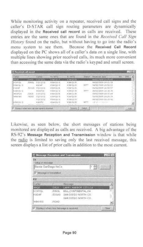
Whi le monitoring activity on a repeater, received call signs and thecaller's D-STAR call sign routing parameters are dynamicallydisplayed in the Received call record as calls are received. Theseentries are the same ones that are found in the Received Call SignHistory found on the radio, but without having to go into the radio'smenu system to see them . Because the Received Call Recorddisplayed on the PC shows all of a caller's data on a single line, withmult iple lines showing prior received calls , its much more convenientthan accessing the same data via the radio's keypad and small screen.
KCaYQL I DNGl CQCQCQ KI6 KQU G Kl6 KQU e 04/02/2009 19:21:28KI6KQU G K6DAF KI6KQU G Kl 6KQU B RPr> 04/0212009 13,,0,13~~6DAF /DOUG CQCQCQ KI6KQU B KI6 VQU B 04/02/2009 lS:S0~07
K16KQU G WOtifZA KI6KQU G KI6 1\QU e RPn 04/0U200916:36:30WD6F:A 12820 COCQCQ KI6KQU B Ki6KOU B 04/02/2009 13,37,49WB6'f'ES 192~\D CQCQCQ KT6KQU G KI6KQU B 04/02/200916::20:2':1
CQCQCQ KI6KQU G Kl6KQU 8 04!Ul/200Y 18:20: 0U
KI6KQU G KI6VFU KI6KQ U G KI 6KQIJ e RPT? --1--1------,--,--
Likewise, as seen below, the short messages of stations beingmonitored are displayed as calls are received. A big advantage of theRS-92 ' s Message Reception and Transmission window is that whilethe radio is limited to saving on ly the last received message, thisscreen displays a list of prior calls in addition to the most current.
Page 90

Received messages are displayed in the lower half of the window.The upper section lets you format and select short messages of yourown . You can have up to five of these, and the one currently showingis the one that will be transmitted .
In the lower left comer of these two windows is a box that can bechecked to have the window pop-up whenever a new record isreceived. Depending upon what you are trying to do, having thesewindows popping up can be annoying. If so, just unclick the Displayswhen new message is received box.
Another usefu l screen that facilitates D-STAR operation is the SelectCall Sign window. This handy screen lets you conveniently configurethe Call Sign Routing Registers.
When operating from a station where you can use a PC, the controland status windows described above can all be placed on the PC'sdesktop and monitored while operating. It's quite informative to seethe data disp layed as calls are received, especially when contactinghams in foreign countries.
Page 91

Page 92
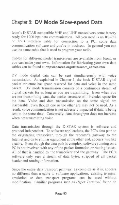
Chapter 8: DV Mode Slow-speed Data
Icoms D-STAR compatible VHF and UHF transceivers come factoryready for 1200 bps data communication. All you need is an RS-232or USB interface cable for connection to a PC, some datacommunication software and you're in business. In general you canuse the same cable that is used to program your radio.
Cables for different model transceivers are available from Icom, oryou can make your own . Information for fabricating your own datacables can be found at http://epaares.org/dstarlicom_cables.htm.
DV mode digital data can be sent simultaneously with voicetransmission. As exp lained in Chapter 1, the basic D-STAR digitalpacket structure has space reserved for data and voice in the samepacket. DV mode transmission consists of a continuous stream ofdigital packets for as long as you are transmitting. Even when youare not transmitt ing data , the packet structure still includes space forthe data . Voice and data transmission on the same signal areinseparable, even though one or the other are may not be used. As aresult, voice communication is not adversely impacted if data is beingsent at the same time. Conversely, data throughput does not increasewhen not transmitting voice.
Data trans mission thro ugh the D-STAR system is software andprotocol independent. To software applications, the PC's data path tothe originating transceiver, through the repeater's gateway to theInternet and on to similar equi pment at the other end, appears just likea cable. Even though the data path is complex, software running on aPC is not invo lved with any of the packet formation or routing issues.All of that is hand led by the transceiver and the gateway. The PC'ssoftware only sees a stream of data bytes, stripped of all packetheader and routing information.
Since the entire data transport pathway, as complex as it is, appearsno different than a cable to software applications, existing terminalemulation or data transport programs can be used withoutmod ification. Familiar programs such as Hyper Terminal, found on
Page 93
most PC's, and ProComm, a long time favorite for modemcommunication, can read ily be used. The catch is that the user at theother end has to either use the same program, or one that is at leastcompatible with the data that is being sent by the originating program.
D-STAR Oriented Data Communication SoftwareOf course, hams are never satisfied with just making do with what isreadily avai lable. Several have developed O-STAR datacommunication software applications that seek to improveperformance and capability beyond programs originally developed forold-style modem communications. Whi le there are a number of 0 STAR data communication programs out there, the two most popularseem to be d*Chat and D-RA TS.
d*Chat (O-STAR Chat) is a simple to use Windows based keyboardto-keyboard communication application . Keyboard-to-keyboardcommunication on O-STAR is somewhat similar to using RTTY orPSK3 I, except text data is transmitted a line at a time . This isprobably the program to use if you want to experiment withkeyboard-to-keyboard communication with a friend or two .
D-RATS on the other hand , while still capable of keyboard-tokeyboard communication, sports a much more extensive list offeatures such as: file transfers, GPS position reporting, mapping,message filtering, email reception and forwarding, and even a methodfor creating and using forms. Several premade forms can be used forsending eMail, radiograms and other purposes. Also included areseveral sample forms for supporting EMCOMM incidentcommunications. Exist ing forms can be edited to suit your purposes,or you can create your own . D-RA TS is a multi-platform applicationthat can run on Windows, Linu x/UNIX and MacOS X operatingsystems.
In addition to using radios to transfer data over RF links , O-RATS iscapable of transfering emai l and other data between RF links and theInternet, thus providing a bridge between radio and Internetcommunications. An additional capability, added in Ver 0.3.0 is theability to save and work with maps downloaded from the Internet,
Page 94

Radio I PC Configuration for Low-speed data OperationSetup for low-speed data operation is relatively simple. Other thanconfiguring the PC communication software application that will beused, there are three things to be concerned about on the radio:
• Serial port settings• Selection of Automatic or PTT triggered data transmission• Disabling GPS transmission
Configuring Serial PortsThe serial port data rate for some leom transceivers is fixed; forothers it can be set via a setup menu. This chart identifies serial portdata rate setting capability by radio model.
Radio Fixed Use MenuModel Data Rate to Set
IC-2820 9600 bps naIC-80AD na 4800 / 9600 bpsIC-91AD 38.4 kbps naIC-92AD 38.4 kbps naIC-V/U82 na 9600 bpsIC-2200H na 9600 bps
ID-800H na 9600 bps
ID-880H na 4800 / 9600 bps
The PC's serial port must be set to match the radio's serial portparameters as follows:
• Baud Rate Set as per the above chart
• Data 8 bit• Parity none• Stop bits 1 bit• Flow control Xon / Xoff
Typically the PC's serial port parameters - are set using the PC'scommunication software application.
Page 95

Automatic I PTT Data Transmission SelectionOn all D-STAR compatible leom radios , except for the IC-V/U82there is a menu for selecting either Automatic or PTT triggered datatrans miss ion. PTT is typ ically the radio 's default condition, andlimits data transmission to when the microphone 's PTT key ispressed. When set to Auto , the radio will start transmitting datawhenever it shows up from the PC's communication softwareapplication. (The rc-V/U82 is fixed to operate in the Auto mode .)
Typically when transmitting data , the radio should be set toautomatically initiate transmission whenever data is received from thePc. But you need to keep in mind that when operating over arepeater, especially if you are linked to a reflector, that the PC willsend data whenever it has it. Sending GPS position data or operatingother "beacon" modes can be a prob lem, because it can collide withother user' s transmissions. In the case of sending GPS position data ,the PTT menu option should be selected to prevent continuous"pinging" of the repeater.
The procedures for selecting either Auto or PTT data transmission forthe IC-80AD, IC-9 IAD, IC-92AD, ID-880H and the IC-2820 areshown below. Consu lt the Icom user manual for the IC-2200H andthe ID-800H.
Automatic I PTT Selection on the IC-91AD and IC-92AD:
I . Starting with the DV operating mode selected and a D-STA R repeater frequency being displayed on the screen.
2. Press [MENU], whic h brings up the menu list.
3. Rotate [DIAL] or use [.] / [T] to select DV SET MODE.
4. Press [ ~ ] to the DV SET MODE menu .
5. Rotate [DIAL] or use [.] / [T] to select DV DATA TX.
6. Press [ ~] to the DV DATA TX option setting screen.
7. Rotate [DIAL] or use [.] / [T] to select either PH or AUTO .
8. Press [MENU] to exit and return to normal operation.
Page 96

Automatic I PTT Selection on the IC-80AD and ID-880H:
1. Starting with the DV operating mode selected.
2. Press [MENU], which brings up the menu selection mode.
3. Rotate [DIAL] or use [ ...] / [T] to select DV SET menu.
4. Press [ ~] and rotate [DIAL] to select DATATX submenu.
5. Press [ ~] to enter the submenu.
6. Rotate [DIAL] or use [ ...] / [ T] to select AUTO or PTT.
7. Press [MENU] to return to normal operation.
Automatic I PTT Selection on the IC-2820 :
1. Start ing with the DV operating mode selected.
2. Press [F] to acce ss the function keys
3. Press [MENU] to select the MENU screen .
4. Rotate [MAIN- BAND] to select DV SET MODE screen, thenpress [MAIN- BAND].
5. Rotate [MAIN- BAND] to select DV DATA TX, then press[MAIN- BAND].
6. Rotate [MAIN- BAND] to select either PTT or AUTO.
7. Press [BACK] 3 times to ex it and return to normaloperation.
Page 97

Disabling GPS Mode TransmissionTo be able to transmit slow-speed data with the IC-80AD, IC-91AD ,IC-92AD, ID-800H and IC-2820 transceivers its first neces sary toturn off GPS mode operation, otherwise the radio will not transmitdata. For other radios , consult the Icom user manual to see if GPSneeds to be turned off.
Disabling GPS Transmission on the IC-80AD and ID-880H:
I. Starting with the DV operating mode selected.
2. Press [MENU], which brings up the menu selection mode.
3. Rotate [DIAL] or use [.] / [ ~] to select GPS menu .
4. Press [ ~] and rotate [DIAL] to select GPS-TX submenu.
5. Press [ ~] to enter the submenu.
6. Rotate [DIAL] or use [.] / [ ~] to select OFF.
7. Press [MENU] to return to normal operation.
Disabling GPS Transmission on the IC-91AD and IC-92AD:
I . Starting with the DV operating mode selected and a D-STA R repeater frequency being displayed on the screen.
2. Press [MENU], which brings up the menu list.
3. Rotate [DIAL] or use [.] / [ ~] to select DV SET MODE.
4. Press [ ~ ] to the DV SET MODE menu.
S. Rotate [DIAL] or use [.] / [ ~] to select GPS TX MODE.
(On the IC-9 1AD select GPS MODE)
6. Press [ ~ ] to the GPS TX Mode option setting screen.
7. Rotate [DIAL] or use [.] / [ ~] to select DISABLE or OFF.
8. Press [MENU] to exit and return to normal operation.
Page 98

Disabling GPS Transmission on the IC-2820:
1. Starting with the DV operating mode selected.
2. Press [F] to access the function keys
3. Press [MENU] to select the MENU screen.
4. Rotate [MAIN- SAND] to select DV GPS screen , then press[MAIN- SAND].
5. Rotate [MAIN- SAND] to select GPS AUTO TX, then press[MAIN- SAND].
6. Rotate [MAIN- SAND] to select OFF.
7. Press [SACK] 3 times to exit and return to normaloperation .
d*Chat Application Installation and Setup
d*Chat, written and maintained by Brian Roode, NJ6N can bedownloaded from his web page http://nj6n.com/dstar/dstar_chat.html
Installation is simp le and straightforward following the instructionsfound on the web page. I downloaded the program to my computerby clicking on the link in step 3 of his instructions, which seemed likethe simpler of several options presented. The program downloaded isa .zip file that you can extract to some convenient location. It installsmuch like any other Windows application, placing a dChat2 programentry in your computer's Start, All Programs list.
Start the program by clicking on dChat2 in the All Programs list.When the dChat nj6n window comes up, click on Settings at the top ofthe screen to display the Settings window. Here you can enter yourCall Sign and set the Communications Port Settings by selecting theCOM port that is connected to your radio and it's baud rate. Set thebaud rate to one that is supported by your radio.
Page 99

Sellings
Communication Port Se«ing.
,.................~ f t. Colo, le,. c ol: , )
0 Show QST o Show GPS o RxBeep~
Send Periodic QST Timestamp Tx elay
30 v , Minut es 0 t. " r. 1500 ms
o 8ulfet O Show ASCII ;0 Fillet Duplicate
d Text Mess
Menage 3
Menage"
Message 5
Message 7
South O,ange Amateur Radio A. sociationWWW. $03fa .Olg
Custom Banner Message
The txColor and rxColor button s are used to set the color for text thatappears in the text box on the main screen. I selected red for transmitand blue for receive. The Font button selects the font sty le for textthat is displayed.
The Settings screen contains two area s for pre-formatting message sthat you want to send. In the QST Message area, text that is to bebroadcast on a periodic basis can be programmed. If you want tobroadcast QST messages, set the Minutes pull-down to a suitable timebetween broadcasts. In the screen above , its been set to once every 30minutes, and then check the Send Periodic QST box. Since this willperiodically ping the repeater, you want to be careful about using this .
The Quick Send Text Messages area allows you to program up toseven different messages that can later be easily recalled andtransmitted. These are intended for message s that you might use on a
Page 100
regular basis. These could be for sending a CQ, instructions on howto rep ly to your ca ll, station identification, equipment setup and so on .Once programmed, these messages can easily be transmitted from themain screen at the click of a button.
The Custom Banner Message box lets you customize the banner /header that appears at the top of the main dChat screen. Here youcould enter your own call sign, club identification, special eventidentification or anything else you might think of. This is "windowdressing" and does not get transmitted.
The Logo button is more "window dressing" and lets you select a .jpgimage of your own to replace the logo displayed in the upper rightcomer of the Settings and main dChat screens.
When the Show GPS box is chec ked, incoming GPS / DPRS messageswill be displayed. If too many incomi ng GPS messages get to be aproblem, uncheck the box to filter them out .
The Filter Duplicate box lets you filter out received duplicatemessages based upon the last two Iines of received data.
ormally the Buffer box is left checked, but if you need to see nonline-terminated data (text run together without line breaks), such asmight be received from D-RA TS, uncheck this box .
Normally the Show ASCII box is left unchecked . If checked theASC II code representing the character will be displayed inparen thes is fo llowing each character. This might be used fortroubleshooting or other purposes.
The TxDelay box is used to set the maximum random delay that isused between each line that is sent. A random delay is inserted tohelp avoid co llisions (s imultaneo us transmissions with other stations).No rmally the default setting of 1500 ms shou ld be fine.
When you are finished with the Settings screen, be sure to click theSave button at the bottom to save you work. To go back to the maindChat screen, click on the Settings button .
Page 101
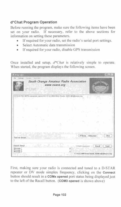
d*Chat Program OperationBefore running the program, make sure the following items have beenset on your radio. If necessary, refer to the above sections forinformation on setting these parameters.
• If required for your radio , set the radio's serial port settings.• Select Automatic data transmission• If required for your radio, disable GPS transmission
Once insta lled and setup, d*Chat is relatively simple to operate.When started, the program displays the following screen.
Fk settJr,Qs C~ct ~
South Orange Amateur Radio Associationwww.soara.org
d'Chat
12:13.43 PM: ~FN connected, versio0"2.1.9 (e)2003BrianRoode, N..6N [email protected] org
Tex110 Send, , •••••__•••• _.__ ". .______ •• • •• m •••__
Ou jcl SendrM·~·;~~oe'~i'..·; Meuotge 2l.~,l!t~~aqe, :) .
COM3 opened. ~~
2. 1.9 lcl 2008 Bflan Roode . NJ6N nf6,n@1;o4tla.Ofg
First , making sure your radio is connected and tuned to a D-STARrepeater or DV mode simp lex frequency, clicking on the Connectbutton shou ld resu lt in a COMx opened port status being displayed justto the left of the Recall button. (COM3 opened is shown above)
Page 102

iIIr,
Transmitting consists of sending some text either by typing in theText to Send box, or by clicking on one of the messages in the QuickSend box, which copies the message to the Text to Send box.
When the data in the Text to Send box is ready to be sent , click on theSend butto n or hit the Enter key on your computer's keyboard. Datais transmitted a line at a time.
If the text you sent is immediately echoed back, and the NO
DIAL TONE error message is displayed, it was not actually transmittedand you may not have selected the correct COM port or baud rate onthe rc.
If you wish to re-send the last line sent, press the Recall button.
If your text box starts to get cluttered, it can be cleared by clicking onthe Clear button.
Pre-formatted small messages can also be broadcast by selecting SendBulletin , under the File pull-down menu . This feature cannot be usedfor file transfers. Instead, it is a way of pre-formatting small multi line messages for transm ission. Messages sent this way show up inother users text window , just like any other messages.
Page 103

D-RATS Application InstallationD-RATS, written and maintained by Dan Smith, KK7DS has morefeatures , and consequently is more complex to use than d*Chat. Danactively encourages user input, periodically providing new releasesimplementing changes requested by D-RA TS users. The currentversion can be downloaded from http://d-rats .com
The descriptions and screen shots in this book were made using ORATS Version 0.3.2 beta. The latest version user manual and otheroperational information can be found under the Documentationsection located on the D-RA TS home page , http://d-rats.com
Insta llation instructions and downloads are provided for theWindows, MacOS X and Linux operating systems. Installation issimple and straightforward following the instructions found underDownloads section of the web page. Select a download suitable foryo ur system type and download the file to a convenient location .
By the way , if D-RATS sounds like a strange name for a program,think about what RATS spe lls backwards. Dan has sense of humor!
Setting up the D-RATS ProgramTo setup the program, start the D-RATS application, either directlyfrom the file it was placed in, or via the Start > All Programs methodused on Windows machines.
From the D-RATS opening screen se lect File > Preferences, whichdisp lays the Config screen as shown below. Refer to the User Manualfound under the Documentation section of the D-RA TS web page, toconfigure the various fields found on this screen.
To get started with basic operation you only need to configure the :Preferences, Paths, GPS, and Radio sections . The default settings forthe other sections wi ll be adequate initially. You can always comeback and configure them as yo u gain experience with the program.One that you may want to experiment w ith later are the three Emailsettings which configure the program for retrieving and sending emailvia the Internet from remote locations which lack a local Internetconnection .
Page 104

v__......._,..,!:;:£i~,
o Enabled
o Enabled
o Enabled
o Enabled
IncorninQ Messages
NewChat: Messages
IncomingPiles
ReceivedEvents
Name lserrse LafreniereSlgn-on MesSbQe 
The Blink tray on feature enables a D-RATS icon in your computer'sTask Bar to blink when different types of messages or files arereceived. Check the boxes of any events for which you want toenable the D-RATS icon to blink . This can be helpful when youeither have other windows open or have been away from the terminaland wish to be alerted to the fact that new data has arrived .
Config File Folder Path Preferences:If you intend to perform file transfers, under the Preferences sectioncl ick on Paths to set a file folder to which incoming files will bedownloaded. In addition to supporting downloaded files , thisdirectory can also be used for uploading or sharing files . Shared filescan be directly accessed by other users. You wi II notice that you canalso select a fo lder for where maps will be stored. It is recommendedthat you not change the default location of the maps folder.
The Form Logo Path is used to store any logo bitmaps that you wish touse with forms. These are not transmitted as part of a fonn, butinstead are used locally as inserts to forms.
If you wish to change the default Paths , clicking on the grey "dotted"button, enables pointing and clicking to where you want to locate thefolders .
Config GPS Preferences:Also under Preferences, by clicking on GPS you can set a fixedLatitude, Longitude and Altitude or enable an attached GPS unit. Ifyou don 't attach a GPS, providing you are connected to the Internet,you can easily lookup and set the Latitude and Longitude by clickingon the Lookup button and entering an address, zip code or anintersection. If connecting an External GPS to your computer, checkthe Use External GPS box to enable it and select the COM port andbaud rate to be used .
Config Appearance and Chat Preferences:Initially, yo u can use the defau lt settings for Appearance and Chatunder the Preferences section. After gaining experience with theprogram, you can come back and fine-tune these to your own liking .
Page 106

ding .wavringin .wavTestSnd.wav
Config Sound File Preferences:The Sounds configuration page allows you to produce differentsounds, depending upon the event, by specify ing the location and filename of .wav sound files . If you don 't have any sound files of yourown, you can searc h your computer system for any files with the .wavfile type. On Windows systems, quite a few sound files can be foundin the C:\i386 directory/fo lder. I selected the following files from mysystem 's i386 directory :
• Chat activity• Message activity• Fi le Activity
Config Message Forwarding Preferences:With the Messages configuration page you can enable automaticforward ing of messages placed in the Outbox to the prescribedrec ipient of the message. In D-STAR fashion, these messages can besent to the node where the recipient station was last heard, oraccording to "static message-routing" rules. The automaticmessaging forwarding feature can be handy when setting upunattended link stations.
The Queue flush interval sets how often the Outbox is scanned foroutgoing messages. For performance reasons, it's recommended thatthis not be set too often . For most purposes, setting this for severalminu tes sho uld be sufficient.
Config Radio Parameters:Click on the Radio section to set the computer's Serial Port and baudrate setting. Using this screen, D-RATS can be configured to workwith multiple radios and even the Ratflector (which allows D-RATSoperation over the Internet without using a radio) . Entries are madeand edited using the Add , Edit and Delete buttons on the bottom of thescreen. For each radio you intend to use, create an entry, setting theCOM port and baud rate to match the rate being used on your radio .
Config the DV Dongle Parameter:An interesting alternative to using a radio for transferring D-RATSmessages and files over the D-STAR network is to select the Dongleport type in the Add a port window which comes up when you clickon Add . As of this writing this is still experimental, but if you use a
Page 107

DV Dongle as your D-STAR network connection medium for ORATS operation, you shou ld only connect through Reflector 15,Module C. Otherwise you may disrupt communication for other 0STAR users . For more information, refer to the Using D-RATS for
Transm itting and Receiving Data section in the following DV-Donglechapter.
Config Transfer Parameters:The Transfer setti ngs window initially can be left at their defaultsettings. If you later experience trouble getting file transfers tocomplete properly, you might try using smaller Block size settings andreducing the number of Pipeline blocks.
When data is being transferred reliably, larger block sizes andpipeline numbers will result in faster throughput. But, if there are alot of retries and retransm issions due to band conditions or whatever,reducing the block size and reducing or eliminating pipeline operationmay result in more satisfactory operation.
Enabling File Transfers:Enab ling Remote file transfers allows other stations to download file sfrom the folder specified in the File Transfer Path set earlier.
Config Network Parameters:The first two network configuration screens TCP Gateway and TCP
Forwarding are advanced methods of forwarding and retrieving TCP /Internet traffic over the radio , most users will not need these.
If you intend to send or retrieve e-mail from the Internet, the threeEmail settings are used to configure your email accounts. Most ofthese parameters should be familiar to those that have setup emailaccounts on their personal computers. Refer to the on-line D-RA TSUser Manual and the Internet Email article available in the HowTos
section of the Documentation link found on the main D-RATS webpage , www.d-rats.com.
Page 108

Use the Ratflector for D-RA18 Experimentation
Accessed via the Internet, the Ratflector allows you to test andexperiment with all of D-RATS modes of operation . Instead ofrouting data out a COM port to a radio , it can be sent over theInternet. Other than that, it essentially works just as if it were an RFconnection to the D-STAR network. You can do just abouteverything that you would normally do over the air , but in this casethe data packets are transferred via the Internet. Since usage isgenerally the same as operating over a radio, you still need toconfigure the D-RA TS preferences as described in the prior section.
Using the Ratflector, you could exchange data with a friend, or usetwo computers side-by-side to simulate two stationsintercommunicating. Using two computers, one as the sending stationand the other as the receiving station, is a really powerful learningtool.
Dan, KK7DS is the provider of the Ratflector and encourages peopleto get on and use it as a learning tool. The convenience of using yourexisting Internet connection makes it easy to run tests and askquestions of users that may be connected. If asked, other users aregenerally happy to oblige with requests to try File and Messagetransfers and other modes of operation .
It's very simple to setup, and I high ly recommend learning how to useD-RATS using the Ratflector before trying to make contacts via arad io. It takes one layer of complexity out of the equation.Information on Connecting to the Ratflector is available in the HowTossect ion of the Documentation link found on the main D-RATS webpage, www.d-rats.com.
Page 109

Configuring Radios for D-RATS OperationBefore running the program, make sure the following items have beenset on your radio . If necessary, refer to the sections earlier in thischapter for information on setting these parameters.
• If required for your radio , set the radio 's serial port sett ings.• Select Automatic data transmission• Ifrequired for your radio , disable GPS transmissions
The following table , from the D-RATS web page User Manual ,summarizes the required menu settings for various D-ST AR radios.
Radio Rate Radio settings required for D-RATS to funct ion
IC-80AD 9600 DATATX = AUTO , GPS-TX = OFF, GPS.ATX = OFF
IC-U82 9600 ATX = ATXON , SPD = SPD96
IC-V82 9600 ATX = ATXON , SPD = SPD96
IC-91AD 38400 DV DATA TX = AUTO , GPS TX = DISABLED, GPS AUTO TX = OFF
IC-92AD 38400 DV DATA TX = AUTO , GPS TX = DISABLED, GPS AUTO TX = OFF
IC-2200 9600 ATX = ATX ON, SPD = SPD96
IC-2820 9600 DV DATA TX = AUTO , GPS TX = DISABLED, GPS AUTO TX = OFF
ID-800H 9600 DVT = DVTAT, SPD = SPD96
ID-880H 9600 DATATX = AUTO , GPS·TX = OFF , GPS.ATX = OFF
10-1 19200 DV DATA TX = AUTO , Cannot use PC application
Page 110

D-RATS Chat Operation
Selecting the Chat tab of the main D-RA TS window allows you toreceive and transmit messages. Anything typed in the send box willbe sent as an entire line, either by clicking on the Send button or bypressing the Enter key on your computer. Unlike PSK3l or otherprograms, text is not sent character-by-character as you type; it's senta line-at-a-time. Sending text a line-at-a-time improves throughputby dramatically reducing the number of packets sent over the 0STAR network.
.t3
09 -11-03 13 :29 :20 ] KK7DS: Now Lha tterded: Not..-cu-d (Port RAT)[ 13 :29:21] WORMT : Now t.r-atteoced: Cn line (D-RATS) (Pe<tRAT)[1 3 :29 :22 ] N< 7A : Now Cnline : Cnline (D-RATS) (Pe<tRAT)[1 3 :29 :23 ] [RAT] N<7A: CQ CQ de N<7A name is Mak QTH M:<\td>ello Californ ia[1 3 :30 : 12 ] [RAT ] N6FN: 1\1(7A. de NtI'N, B€fnie.,Escomido, CP[1 3 :30 :36 ] W9DBE-l: Now Lha ttended ' Cnline (D-R.I\TS) (Pe<tRAT)[1 3 :30 :50] [RAT] f'.1<7A: Hello B€fnie[ 13 :31 :21 ] [RAT] N6FN : $GPCT.oA,1331cl ,'; Hl 820,N,7243 87c ,W,I ,3,o,0,M,O,M,,'7b
.!'''''''''' ,D-RATS S'.olI011
[ 13 :31 :28 ] [RAT] N6FN: HI Mark, jJst sitting r~e tryir') tD figute OJt us,,') D-RA,T$ 3 2t
If you have multiple ports enabled on the Preferences> Radio screen,perhaps D-RATS via an Internet Network connection and a radio ortwo , use the pull down menu button at the left of the chat text entrybox to specify which port to send the text data to .
If you wish to clear the upper text window, click on the View pulldown menu and select Clear. Even after clearing the upper chatwindow, you can retrieve older data by clicking on the View pulldown menu and selecting Log.
Page 111

To pre-format short messages that you might use on a regular basis,click on the Quick Messages button , which allows you to view andselect already formatted messages. Here you can also enter andde lete messages. Quick Messages are transmitted by double-clickingon the message you want to send .
[1-+: 19:56] [RAT] KK7DS: ~-Io prob, o"\''lrYS for mving a flexible
Ping Stations Operation:To determine if any other stat ions are on line, you can send a pingcommand, and any connected D-RA TS stations will respond with thereply that was set in their station 's configuration setup Ping reply box.
By right cl icking anywhere in the Stations windows on the right, youcan select Ping All Stations to determine who is on line and theircurrent Online / Unattended status. Hovering your mouse cursor overa station's ca ll sign wi ll display their current online stat us and whenlast heard .
You can set your own Online / Unattended status by using the pull down selection button under the My Status heading.
You can also ping individual stations by using by right clicking on thestation's call sign in the Stations window. Also by right clicking onthe station's ca ll sign, you can: Test Connectivity, Request Positionand Send file. Test Connectivity sends a number of test packets todetermine the data transmission / reception link quality to that station.
Page 112

Configuring and Sending D-RATS QST Broadcasts
QST message broadcasts can automatically be tran smitted on aperiodic basis . To pre-format QST Messages, click on the QSTs
button at the bottom of the Chat screen. Here you can Add , Edit andRemove QST messages. Click Add to create a new message type andset the delay between message broadcasts.
-::Q5h
T~ Me(!~~ en Cont:er't
Te~ 30 r- 0 ~1'lle. N6FN t~stotlQ QST broadc ..stmes~c~,. .'M'. I i.'¥.#ilU:WttJ42,MJ¥'4#J41"iii.3dUf
Checking the ON box selects the QST Message to be transmitted atthe selected time intervals. Whi le the QST Message is beingdisp layed in the QST window , you will see it counting down thetransmission timer. If you wish , the message can be immediately sentby double clicking it, handy for bypassing the full time period whentesting.
Page 113

Exchanging eMail and FormsSelecting the Messages tab of the main D-RATS window allows youto receive and transmit eMai l messages and a variety of other forms.
stations
LoJ .. .. Iii (RJ L.1' GWIXZI(OO,07)
New Forwtlfd ReciY Delete r-wkR~&:l r'b'kUYe4d $end/R~e U8UO(OO:20)
en Inbox Sender 4 Recipieft.· Subltct .. T)t'pe \II Me ... 'NORMT (00: 20)
01 N6FN NK7A Testo;p"ith atta(~ment. em~ 13:"6:54 ZOO9-11-03 KK7DS (00 :20)
~ Sent 19 N6FN Nt:7A RE: Test email 13:13:53 2009-11·03 !I(ZRXU(OO:ZO)
em Tr<Y..h
• MV.,S~a~!:'S
Online
In addition to sending and receiving email and form s, the programcan also serve as an email forward ing mechanism to RF nodes notconnected to the Internet. This enables remote D-STAR nodes to beab le to send and receive emails w ith either Internet or RF nodeconnected destinations.
To create an emailc click on New and then select email from the list ofpre-formatted forms. The Email Message form comes up where youcan compose your email, and add attachments you may wish to send .(Keep attachments sma ll, preferably under I Kbytes .)
After saving the email, it goes to the Outbox, and can be manuallysent by highl ighting the document and clicking on the Forward button .This same button is also used to forward received messages to otherInternet or RF node connected destinations. Alternatively,Send/Receive can be used, which sends all emails in the Outbox ifAutomatic Forwarding is enabled in the Config Messages screen .
For further deta ils on the configuration and use of email and formcapabilities, refer to the on-line D-RATS User Manual and theInternet Email article availab le in the HowTos section of theDocumentation link found on the main D-RA TS web page , www.drats.com.
Page 114
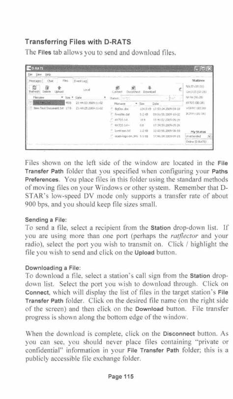
Transferring Files with D-RATS
The Files tab allows you to send and download files .
MesS~,,,Ch<tt F~o!"S 1Event:l09 i
r ~-i I1f +p.t!r.~~ ! l)e~te ~d
FlIeNme .. Sue • Date
.~ ~ ..COf"lt'le(t t-s<cnnect Download
KlC1DS.txt 186 17:"O:o.?2'009-f)S-.21i
.... rK7DS.t;d.... 08 17:39:50 2009-05·26
L~v.y..e , b:t 1.0 te8 12:00:55 2009·06· t8
~_ oce-m4¢oo·s:m.]P<; S.OKB 17:"~ : 34 W09'09 -1 ~
Files shown on the left side of the window are located in the FileTransfer Path folder that you specified when configuring your Paths
Preferences . You place files in this folder using the standard methodsof moving files on your Windows or other system. Remember that 0 STAR's low-speed DV mode only supports a transfer rate of about900 bps, and you should keep file sizes small.
Sending a File :To send a file , select a recipient from the Station drop-down list. Ifyou are using more than one port (perhaps the ratflector and yourradio), se lect the port you wish to transmit on. Click / highlight thefile you wish to send and click on the Upload button.
Download ing a File:To download a file, select a station ' s call sign from the Station dropdown list. Select the port you wish to download through. Click onConnect, which will display the list of files in the target stat ion's FileTransfer Path folder. Click on the desired file name (on the right sideof the screen) and then click on the Download button. File transferprogress is shown along the bottom edge of the window.
When the download is complete, click on the Disconnect button. Asyou can see, you should never place files containing "private orconfidential" information in your File Transfer Path folder; this is apublicly accessible file exchange folder.
Page 115

File Transfer ProblemsIf text and quick messaging are working fine , but you are havingdifficulty transfering files, you might try performing a ConnectivityTest to assess the condition of the radio link . Unlike DV Voice,which has error correction built into the protocol, DV low-speed datamode has no error correction mechanism. Thus it is important to havea high quality radio connection for fi le transfers to be successful.
To test the reliability of a connection, right-click on the desiredstation in the Stations window and se lect Test Connectivity . Here youcan experiment with Multiple fixed-size packets and Gradually
increasing packet sizes, to try and determine an optimum packet size.Click Forward and either accept the default parameters, or modify tosuit, then click Forward again and then press the large Start button torun the test.
Data Block Transfer Problems: Best throughput performance will behad with larger block sizes. If you are hav ing trouble completing filetransfers, a high block size may prevent you from getting blocksthrough. Reducing the block size reduces the odds of incurring errorswithin each block, wh ich may reduce file transfer difficulties.
To change the default block size, under the File pull-down menuselect Preferences and then Radio> Transfers, on the Config screen.The program defau lt block size is 512, which is relatively large . Tosee if smaller block sizes can alleviate block transfer problems, youmight try block sizes of 256 or 128. Like wise , you might tryreducing or eliminating Pipeline blocks.
Mixing File Transfers with voice: This is from the D-RATS web page."Because of the effect t iming has on the ability to detect failed ormissing blocks and retry , interrupting a file transfer may causeproblems. Ta lking on the digital voice side while doing a file transfercan cause the transfer to time out. Try to avoid talking while sendinga file if possible."
Page 116

Other D-RATS Capabilities
The above sections describe the main features and functionality of theD-RA TS application. However, there are additional features thatadvanced users may find of interest. Further information on these canbe found under the HowTos section of the Documentation link foundon the main D-RA TS web page, www.d-rats.com
TCP Forwarding: From the D-RATS web page: "D-RATS hasgeneric TCP forwarding support. This means you can pipe some TCPtraffic across the radio to a remote station . This may be useful forbridging SMTP traffic to a remote location or for doing POP3 forremote mailbox acces s. In it's native form, this will be rather slow ,given that most of the protocols likely to be used in this fashion arevery chatty and depend on a lot of back -and -forth handshaking tocomplete. While you shou ld be prepared for this , the functionalityshould still be useful. "
D-RATS Repeater I Ratflector Operation : D-RA TS also has arepeater program, which can be used as a repeater with multipleradios, or as a network proxy (instead of or in addition to the repeaterfunction). The D-RATS Repeater program is downloaded along withthe main D-RATS application and is found in the same programgroup.
Connecting D-RATS to a DPRS Interface: Two separate pieces ofsoftware, D-RATS and DPRS Interface developed by Pete LoveallAE5PL, can be configured to operate simultaneously across a DSTAR radio's low speed DV channel. DPRS Interface is designed topass GPS-A DPRS messages received from a D-STAR radio's lowspeed DV channe l and pass them on to the APRS-IS network where itis com bined with APRS and DPRS traffic world-wide.
Mapping Capability: A separate D-RATS Map Downloader program,found in the D-RATS program group, is capabable of downloadingand loca lly caching map segments from the Internet. These maps canthen be used to make measurements, track multiple stations or otherassets using GPS, and includes support for dynamic sources such asNBDC Bouy and NWIS River Status.
Page 117

Page 118

Chapter 9: DV Dongle, D-STAR Adapter
Besides being a solution for hams that don't have local access to agateway equipped D-ST AR repeater, the DV Dongle is fantastic forquickly and easily connecting to gateways and reflectors all over theworld. It's especially suited for situations when you are out of townand want to get back into your local repeater.
Developed by Robin Cutshaw, AA4RC and Moe Wheatley, AE4JY,the DV-Dongle provides an alternative method for participating in DSTAR communications without using a radio .
Housed in a small semi-transparent blue plastic enclosure, the Dongleconnects to your computer's USB port via a short interface cable .Since world -wide D-STAR communications are facilitated by sendingdigitized voice packets over the Internet, the only thing a PC needs tobe able to participate in D-ST AR communications is some suitablesoftware and a means of encoding and decoding D-STAR's digitalvoice streams. Taking advantage of a PC's high speed USB 2.0 dataport, circuitry inside the Dongle uses an AMBE digital voice CODECto encode and decode voice data streams to the D-ST AR protocol.Robin Cutshaw's, DV Tool software than takes care of transportingthese data streams back-and-forth over the Internet to remotegateways and reflectors.
Page 119
Computer System RequirementsThe DV Dongle application needs a relatively fast computer to runproperly. It's recommended that you have a 2 GHz or faster machine,and turn off any compute intensive applications to prevent dataoverruns between your computer "and the Dongle . The Dongle's redLED flashes whenever overruns occur. I first tried installing on anolder I GHz system, and performance was unsatisfactory. Operationon my Intel Dual Core 1.6 GHz laptop is quite usable, however.
Note: As of vers ion 2.0x, Robin, AA4RC, has rewritten theapplication to run native ly on the supported operating systems,instead of running Java as in the I .x versions. This significantlyincreased performance, and the application may now be able to run onsystems where it had previously been marginal running Java.
In addition to a fast computer, you also need a high speed Internetcon nection. Dial -ups will not work. The Internet service that comesbundled with my cable TV subscription worked fine .
If you don't already have one , you will need a headset andmicrophone that is compatible with the audio jacks on your computer,typica lly 3.5mm (1/8") audio jacks. There are a lot of inferior qualityheadset / mic products being sold for the mas s-consumer PC market;for optimum voice reception and transmission you will want to get ahigher quality unit. Most of the cheap units have small ear cuffs thatdon't block out ambient no ise and quickly become uncomfortable towear.
If an Audio System Event window pops up when inserting themicrophone into the PC' s microphone jack, select Microphone fromthe options presented, otherwise you may experience degraded or noaudio recording.
Installing the DV Dongle Software on Your ComputerAfter purchasing a Dongle, the latest full release version of the DVTool software is downloaded from the DV Dongle web page.http://dvdongle.comIDV_Dongle/Home.htmI Beta test versions can bedown loaded from http://www.opendstar.org/tools/
Page 120

On the DV-Dongle Home page, clicking on the Installation tabaccesses installation instructions and sample screen shots. Here youwill find different software downloads targeted for the MicrosoftWindows, Mac as x Leopard, and Linux operating systems.
ote that on Windows systems, inserting the Dongle will bring up theFound New Hardware Wizard to assist you with installing therequired USB dr ivers. Installation of USB Drivers on MicrosoftWindows is a two-step process, bringing up the Found NewHardware Wizard two times. Make sure you complete both installs.
After insta lling the USB dr iver, you can download the DV Toolsoftware app lication to a suitable place on your computer. Idownloaded it to a DVTool sub-fo lder I created in the my ProgramFiles directory.
After downloading the file to whatever location you prefer, theapplication is started by double-c licking or opening the DVTool2.xx.exe fi le. Rather than having to open the folder whe never youwant to run the program, you might want to put a shortcut to theprogram on your desktop or in the PC' s START menu.
On Windows, to place a short cut on the desktop, right click on theDVTool-2.xx.exe file and select Send to Desktop from the pull -downwindow that pops up. To insert a shortcut into the START, AllPrograms menu, drag the DVTool-2.xx.exe file to the START button;wait until the All Programs option shows, and then drop/place theshortcut where you want it to appear in the list of programs.
Selecting the DV Tool COM port and Audio DevicesOn the DV Dongle home web page; select the Using the DV Dongletab to access the DVToo l operat ing instructions. Before starting theprogram, make sure the DV dong le is plugged in. Upon starting theprogram ver ify that the ser ial port showing in the DV Device windowis co rrect. Ifnot, select the correct one from the pull-down list.
Page 121

CloVTool 2.0beta4 ~JO]r8J
File Help
Ovrool - - - - - - - - - - - - - - - - - - - - - - ----,
lvIyCallsign: IN6FN
DV Device: IcolvlS
My Message:
:::J Open!'ame;
Senal It :
Connection I Info I Hist ory I Dat a I Ut ilities Setu p IAudio I Gateways I Look and Feel I
Enter your Callsign, and if desired a short 20 character or lessMessage. This message capability is the same as found on leom's DSTAR radios and will be transmitted along with your voice everytime you transmit.
Next verify that the Audio Input and Audio Output devices selected arethe ones you want to use, by selecting the Setup > Audio tabs. Ifunsure, leave the default settings for now, you can come back to thisand try other settings while doing audio loop back testing.
Click on Open to establish communication with the DV Donglehardware. If all is well , you should see the Name and Serial # fieldsfilled in as shown below. If communication was not established, youmay have the wrong COM port selected. Try a different setting.
COVTool2.0beta4 (g1£)r8JFile Help
.·Ovrool· ······· -- · ·..·-·..-· ·-· ·--·-..-..-..- --.--- -.. --- ---- ----.-.--------.--- ----..--.--..-.. --..--.----.--,
My Callsign: I .- My Message: IBernie, Escondido CA
DV Device: Close I tJame; DV Dongle
Serial # ; DVOS1578
Connect ion I Info I Hist ory I Data I Utilit ies Set up IAudio I Goteways I Look and Feel I
Audio Input :
Audio Output:
IS igrnaT~1 Audio
Ir;m'Ij'j!i)-a:rmn•
Page 122
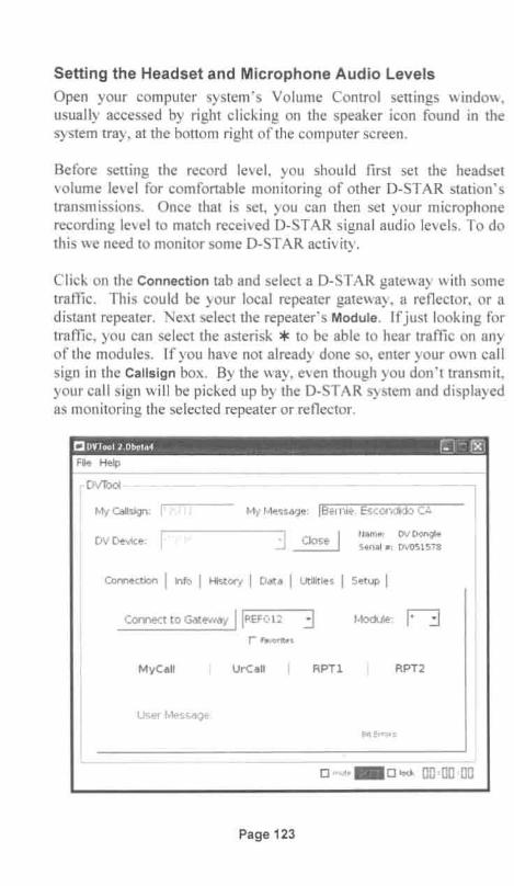
Setting the Headset and Microphone Audio LevelsOpen your computer system 's Volume Control settings window,usually accessed by right clicking on the speaker icon found in thesystem tray, at the bottom right of the computer screen.
Before setting the record level , you should first set the headsetvolume level for comfortable monitoring of other D-STAR station 'stransmissions. Once that is set, you can then set your microphonerecording level to match received D-ST AR signal audio levels . To dothis we need to monitor some D-STAR activity.
Click on the Connection tab and select a D-STAR gateway with sometraffic. This could be your local repeater gateway, a reflector, or adistant repeater. Next select the repeater 's Module . Ifjust looking fortraffic, you can select the asterisk * to be able to hear traffic on anyof the modu les. If you have not already done so, enter your own callsign in the Callsign box . By the way , even though you don't transmit,your ca ll sign will be picked up by the D-STAR system and displayedas monitoring the selected repeater or reflector.
CIDVTool 2.Dbeta4 r~:J~Jrg]File Help
·D VTool ""._- _...._........_-----_. ----- -_._. ............._......._....- ............._---_..__.- ··_·.·__···__·__ ·_·___ ."W"."._·"'·•
My Calisign: j;i>;ij My Message: IBernie, Esconcliclo CA
I j Close INam~: DVDongle
DV Device:S~ri a l # : DvOS1578
Connect ion I info I History I Dat a I Ut ilit ies I Set up I
Connect to Gateway IIPEF012 3 Mod ule: nr Pevorttes
My Call UrCall I RPTl I RPT2
User Message:
IBit errors.
,-_.._-----~-._-_..__.-
D mut."D I~<k [J[J :[][] :[][J
Page 123

Once the call sign of the repeater or reflector to be monitored hasbeen set, and your own call sign has been entered, click on theConnect to Gateway button to begin monitoring. If you don 't hear anytraffic on the selected repeater, you can access the last heard list athttp://dstarusers.org/lastheard.php to find repeaters with activity.
Monitor a few stat ions, adjusting the volume control for acomfortable listening level. As with conventional FM repeaters, youmay notice volume leve l differences between received stations. Ifnecessary, select a compromise vo lume setting that allows all stationsto be comfortably heard .
Once your listening volume has been set, press the Disconnect buttonto disconnect from the D-STAR system so that the microphonerecording leve l can be set. On a Windows machine, to access yo urcomputer's microp hone level control, select Properties under theOptions pull-down of the Volume Control window. This brings up theProperties window where you can se lect the Recording button, whichin-turn displays the Recording Control window. If multiple recordingdevices are displayed in the, ena ble the Microphone setting.
Click on the Setup > Audio tabs and then click on the Test AudioUsing Soundcard Only button . Whi le listening to your own voice,adjust the Microphone level control to match the listening level setearlier.
If you want to verify hear how your digitized voice will sound overthe D-STAR network and verify the performance of the DV Dongle,press Stop Soundcard Test, and then click on the Test Audio Using DVDongle button. Here it will be a bit easier to monitor your own voice,as it is delayed by a few seconds.
DV Dongle OperationIn setting the vo lume levels , we have already covered how to monitora D-STAR node. To transmit, just press and hold the PTT button. Ifit is grayed out preventing transmission, and the asterisk * has beenselected as the Module, you need to select a valid module, either A, Bor C. The PTT button can also be grayed out preventing transmissionif you are not registered for gateway transm ission .
Page 124

Be aware , that at least on Version of the DV Tool software that I wasrunning, it was poss ible to select a module that is not physicallypresent at the repeater site . In that case, I don 't know where yourtrans mission actually goes.
Connection I Info I History I Data I Uti lit ies I Setu p I
JvIodlJle: 'Bl3Disconn ect_____llpH012 :.:oJ
MyCali UrCal!
KJ6ACO / DOUG CQCQCQ
RPTlREF012 A
RPT2KI6KQU G
User Message : FALBROOK AIRPARK
Bit Errore : OJ S
Listening to KJ6ACO o mut· 1IiI 0 lock 00:00 :2Y
The lock function box can be selected if you wish to change the PTTbutton to operate as a toggle for transmit and receive. When set,clicking PTT once enables transmission, clicking a second timereturns to receive .
You may notice, that some repeater nodes do not appear in theConnect to Gateway selection box. This can be for a variety ofreasons , as only gateways that are currently running the required DVDongle access software and have their IP ports properly forwardedwill be displayed.
Besides being able to select gateways via the pull-down menu , youmay find it faster to type in a desired gateway's call sign. By clickingon the Connect to Gateway box and quickly typing you can enter firstcoup le of characters of a desired repeater's call sign, which selects thefirst ca ll that matches the portion you entered, a fast way to specify aconnection.
To further simplify selecting gateways, you can create a list offavorites by accessing the Setup > Gateways tabs. Once created, yourlist can be used on the Connection tab by clicking the Favorites box .
Page 125

Gateway Information TabClicking on the Info tab window's Get Gateway Info button retrie ves avariety of information about the currently connected Gateway. In thescreen shot below , all repeaters linked to Reflector 21 are shown atthe left. Dongles currently connected to the repeaters and to thereflector are shown in the middle. A list of stations most recentlyheard on this reflector is show n to the right.
Connectio n Info I History I Data I Utilit ies I Setup IREF021 software vers ion: 1.2 1 Dat e: 2009/1 1/0621:37:51 urco
Linked Repeaters : DV Dongle s: Last Heard:
• .GB7CD BGB7DB B.. :GB7GL BGB7SY B .:.J
A: GB7....B.A : GB3'l'iEN6FfJ
A: G45ZI'1A: GOELOA: "10RHVA: '·BOP"'"A: G6\~ZA
A: G6GVH
10 :49:1 2 •10 :01:4508 :00 :2407 :05 :0706 : 15 :2603:01 :57 .:.J
Get Gateway Info I
o mute o 10" 00 :O[] :DO
Recently Heard Station's History TabThe History tab window records and time-stamps all stations heard onthe current connection. This data can also be saved to a file .
Connectio n I Info Hist ory I Dat a I Ut ilit ies I Setup I
11106
Time
11/ 06 11 : 38: 04 KJ6CDA
REF01 2 .A jK I 6MGN C
REF01 2 A :KI 6MGN Cj
REF0 12~ lK I 6r1f~~ C
REF01 2 A IKI 6KOU 031_
COCOCO REF012 A :KI 6JKA G
'''"' " .,;.." ""en .,nm" cnmcn "" 000 • ""m, d ISave file I I Browse I r gray dups~
---_._._ - -- --o mute 0 lock 00 :00 :00
11/ 06 11 :38:23 KJ6.A.CO 'DOUG COCQCQ-_._--+ - -{-- ---
11/ 06 11 : 39:41 K1GR ID800 COCQCO. ~ ~ -_of
11/ 06 11 :4 0 : 22 KJ6CDA !2820
Page 126
-- --._- - - - --
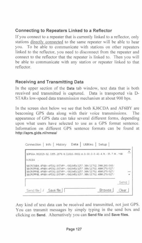
Connecting to Repeaters Linked to a ReflectorIf you connect to a repeater that is currently linked to a reflector, onlystations directly connected to the same repeater will be able to hearyou. To be able to communicate with stations on other repeaterslinked to the reflector, you need to disconnect from the repeater andconnect to the reflector that the repeater is linked to. Then you willbe ab le to communicate with any station or repeater linked to thatreflec tor.
Receiving and Transmitting Data
In the upper section of the Data tab window, text data that is bothrece ived and transmitted is captured. Data is transported via DSTA Rs low-speed data transmission mechanism at about 900 bps.
In the screen shot below we see that both KJ6CDA and AF6BY arebeaconing GPS data along with their voice transmissions. Theappearance of GPS data can take several different forms , dependingupon what users have selected to use as a GPS format sentence.Information on different GPS sentence formats can be found athttp://aprs.gids .nl/nmea/
Connect ion I Info I History Data I Ut ilit ies I Set up I~
~GPGGA , 062829.02.3355.2679 . N.1l816 . 090)2 , i'i, 0 , 00, O. 0 , 43 . 4, Ii" 35 . 7 .n., ' 68
KJ6CDA .
a CRC5684 , AF68Y>API92, DSTAR' : / 06E ,45: 3257 . 3Bt1l1l702 . 3911.260/000/H CRCFF6E, AF68Y>API92, D5TAR' : / 061945: 3257 . 38N11l702. 4S1i1< 270/ 0271H CRCFF6E. AF68Y'>API92 . DSTAR' : / 061945: 3257 . 38N/ 1l702 . 48/ik270 / 0271H CRCFF6E, 4F68Y>API92 , DSTAR' :1061945: 3257 . 3BN/ 1l702 . 4Si1. 270 /027 /
Send file I I Save file I I
Send I
Browse I Clear I
Any kind of text data can be received and transmitted, not just GPS.You can trans mit messages by simp ly typing in the send box andclicking on Send . Alternatively you can Send file and Save files .
Page 127

Using D-RATS for Transmitting and Receiving DataWhile the ability to tran sport data via D-RATS through the DVDongle port was still experimental with the beta version of software Iwas using, and not completely bug free, I was able to exchange textdata with other stations.
The following screen shots of D-RATS and DV-Tool are two view sof the exac t same data exchange session. The same data shows inboth screens, albeit displayed differently . During these exchanges,others and I alternately exchanged short messages, either directlyfrom the D-RATS Chat screen or via the DV-Tool's Send box .
Sta tions
tole ~oew tlo<>
t.;~r~, ..~1;~·,JI~~~~7"~7~ij~;i;;:············=······ ,===.. ~. WORM. (00'02)
,[ 16 :0 1:11] [DV Dongle] KF4IRC: W85P13 in Colcrado . Reed you- position """"((00"",end temp fine. N6FN tool send 100%
[16:01 :45 ] [D V Dongle] WORMT : WORMT menitcring en WOCDS port C " ){>SCoo 23)
lirk ed to REFO lSC[16:02:59 ] [DV Dongle ] N6FN: WlYMT, data recerved finE both on D-RATS
end en DV·Too l screeos[1 6 :03 :32] [DV Dongle ] KF4IRC: KF41RC off to c1lb meeting to oo demo 73
to all
Connect ion I Info I History Data I Utilit ies I Setup I( SOB ) "~-@-@->7E-@(J! - -- - - - -! - -- --- - IIllIlIIl (EOB )(SOB) "-@-@(J-@fs £ -,~IKF4IRC --COCQCQ--WB5PJB in Col orado . Recd your posi tionand t eap fi ne . N6FN t ool Send l ()O~( E()B I
(SOB) "- @- @-@->7E- @(J I--- - - - - !------- OCIIDIJl](EOBI(SQB!"- @- @(J-@:O=@2fiOPHT- - -CQC OCQ- -WOl'l-IT Monitor in g on WOC[.oS por t C linkedt o PEFOl'SC IEOB )ll5Ftl:Drat s t rans mit1l5FII:Drat s t ransmit ( SOe l " -@-@-·~->7E-@O ! -------!-------DDIIIIlOO (ECOBI(SOBI "- @- @O- @IU-@/ KF4IPC--CQCOCQ- -KF4IPC off to cl ub m~etin9 t o do demo
Send file I / Save file I I
Send I
Brow se I Clear I
Page 128

I didn't have to do anything special. Apparently, the author of oRATS, Dan Smith - KK7DS and the author of DV- Tool , RobinCutshaw - AA4RC must have collaborated in making this work.Assuming you have D-RATS installed and running, all you need do isconfigure the D-RA TS Radio Preferences by adding a dongle porttype as shown below.
IeConfig ,,' '" , '
a Preferences:
Paths
GPS
Chet
Sounds
Messa.Jes
Transfers
13 Network
TCP G:~teway
repForwardIng
Outgoing EtMiI
Incoming Emad
EmadAccess
Enobled ' !POft ' i?~ngs~._?p~~,~t.:...l~~~~~'!o net:ref. d-'et ' .com:9000 0 0 RAT
o dongle: 0 0 DVDongle
o 9600 0 0 DEFAULT
Once a D-RATS DV-Dongle port has been configured as shownabove , it's a simple matter of selecting the Dongle port to the left ofthe Send box, in the D-RATS Chat screen. After that , its fairlysimple , you just use the programs as intended.
As of this writing there is a caution: you should only connect throughReflector 15, Mod ule C. Otherwise you may disrupt communicationfor other D-STAR users.
Dongle LED Status IndicatorsFour LED indicators, visible through the semi -transparent plastic casecommunicate the DV Dongle 's operational status. A blue LEDflashes whenever data is being transmitted from the computer and aflashing ye llow LED indicates that data is being transmitted back to
Page 129
the computer. A slowly pulsing green LED indicates that the deviceis idle. More importantly for assessing performance, the red LEDindicates either data overruns or under runs between the computer andthe Dongle. Occasional overruns aren 't too bad , but frequent flashingof the red LED indicates a slow computer. Shutting down otherprograms may help; otherwise you will need a faster system.
Installation ProblemsA variety of problems can prevent DV Dongle operation. One ofthem is that firewalls protecting your computer, network or routermay prevent the program from communicating over the Internet.Other problems may arise with getting volume controls set, or beingable to record from the microphone.
If you are having difficulty, the Yahoo DV Dongle group found athttp://groups.yahoo.com/group/DVDongle may be able to provideassistance. With hundreds of postings covering ju st about any type ofprob lem you can imagine, you sho uld be able to find one that matchesyour problem. If you can't find a solution in the threads that arealready posted, you might try registering and asking a question ofyour own .
Page 130
----- - -_._-
Appendix A: D-STAR Web PagesHere are additional D-ST AR web pages that you might find useful.
D-STAR Users, Source for D-STAR Informationhttp://dstarusers .orgllastheard.php has last heard lists, D-STARrepeater directory, gateway registration links and links to D-STARaccessory hardware and software and more .
D-STAR Information, FAQ's and Morehttp://www.dstarinfo.com D-STAR news , applications, links, nets,reflectors and more .
K5TIT The Texas Interconnect Teamhttp://www.k5tit.org/ Repeater group in Texas, lots of usefulinformation.
Instructions for Making Icom Radio Interface Cableshttp://epaares .org/dstarticom_cables.htm GPS interface and PCprogramming cab le-wiring diagrams for home made cables.
WY1U 's D-STAR Repeater and Reflector Finderhttp://home.comcast.net/-timmik/dstarsearch.htmlgood forlocating repeaters in different parts of the world .
APRS-IS I DPRS Informationhttp://www.aprs-is.net/operating information, APRS-IS activity,APRS / DPRS conversion, software, specifications and more.
Enabling GPS Position Reporting through D-STARhttp://www.nj6n.com/dstar/ translating Icom GPS data to becompatible with APRS. Includes sample APRS radio setup guides.
Yahoo D-STAR Forum I Grouphttp://groups.yahoo.com/group/dstar_digital/ International 0STAR discussion group, prob lem solving, and other topics
Page 131

Icom Tech Support Knowledge Basehttp://www.icomamerica.com/en/support/kb/Default.aspxSelect the follow ing pull -downs for all D-STAR art icles .Product Line: AmateurProduct Class: D-STARModel: Ge neralBalance of fie lds leave blank, Press Search
d*Chat Communications Software Home Pagehttp://nj6n.com/dstar/dstar_chat.htmIFeature list, softwaredownl oad, installation instruct ions.
D-RATS Communications Software Home Pagehttp://d-rats.com/ Feature list, screenshots, software downl oad,insta llat ion instructions, user forum, FAQs.
D-StarCom Icom .icf Radio File Conversion Utilityhttp://dstarcom.ae7q.netl Program for converting Icom .icf filesfrom one radio type to another.
jFindu Home Pagehttp://www.jfindu.net Last heard lists , D-STAR Repeater and DPRSact ivity, D-STAR repeater locator map and more.
DV Dongle Home Pagehttp://dvdongle.comIDV_Dongle/Home.htmITechnical info,Installation instruc tions, Software screenshots , FAQs
DV Dongle Yahoo Support Grouphttp://groups.yahoo.com/groupIDVDongle DV Dongle disc uss ion andsupport.
RT System's Programming Softwarehttp://www.rtsystemsinc.com/index.cfm RT System's home page .Radio programming software and cab les.
Page 132

Appendix B: Error Code Listings
If the Call Sign Registers are not programmed correctly, or otherproblem situations are detected, either by local or "distant" repeatercontrollers, error codes can be returned to the transmitting radio.Error codes appear as text messages, which scroll across the radio 'sdisplay.
The error codes shown below may not be a complete list of possibleerror codes, and they may be displayed somewhat differentlydepending upon the model of radio be ing used.
Error Code Repeater Mode Possible Cause
Local Repeater, or No answer from other station, normal opera,
UR?AA1AAADifferent Repeater in MY call sign not programmed
same Zone UR call sign not programmed(Local Repeater
No answer from other station, normal oper,Node call sign)Through Gateway Wronq callsicn proqrammed in RPT2
Suffix"G" not added toRPT2 callsign
Local Repeater, orRPT?AA1AAA Different Repeater in Wrong callsign programmed in RPT1(Local Repeater same Zone orNode call sign) Wrong callsign programmed inRPT2
Through Gateway
RPT?BB1BBB Different Repeater in(Other Station's same Zone or RPT2 isbusyRepeater Node Through Gateway
call sign)MY call sign not programmedMY call sicn isincorrect
RPT?AA1AA_G MY call sign isnot reolstered on serverUR call sign not programmed
(Repeater's Through GatewayUR call siqn isincorrectGateway call sign)UR call slon isnot reolstered on server"/" is not 1st character of UR callsign whenusing Repeater Node Routinq
Page 133

Append ix C: leorn Radio Setup Guides
Nifty Ham Accessories produces laminated guides for almost allKenwood, leom and Yaesu radios sold since the year 2000.
Nifty setup and programming guides are available from most hamradio retailers and also directly from Nifty Ham Accessories.
oICOM
Nifty! Quick Reference GuidesAvailable for all recent Models
Condensed and si mpli fi ed step-by-step operatinginstructi ons for all menus and mo des of operati on.
Page 134

0ICOM
Reference Guides
IC-T2H IC-91A / AD IC-718
IC-T7H IC-92A / AD ID·880H
IC-Q7A IC-207H IC-746PRO
IC·P7A IC·208H IC-756PRO
IC-V8 IC-910H IC-756PRO(II)
IC·R20 IC·2100H IC·756PRO(III)
IC-T22/42A IC-2200H IC-7000
IC-W32A IC-2720H IC-7200
IC-T81A IC-2820H IC-7600
IC-V85 IC-703 (P) IC-7700
IC-T90 IC-706MKII IC-7800
IC-80AD IC-706MKII(G) IC-V8000
Nil, I ("~I tv HamAccessorkk760-781-5522 www.niftyaccessories.com
Page 135

Page 136