I.F.S. EXAM-(M) 2018 FSI-P-CVLE
12
I.F.S. EXAM-(M) 2018 FSI-P-CVLE CIVIL ENGINEERING Paper - I Maximum Marks : 200 Time Allowed: Three Hours Question Paper Specific Instructions Please read each of the following instructions carefully before attempting questions: There are EIGHT questions in all, out of which FIVE are to be attempted. Questions no. I and 5 are compulsory. Out of the remaining SIX questions, THREE are to be attempted selecting at least ONE question from each of the two Sections A and B. Attempts of questions shall be counted in sequential order. Unless struck off, attempt of a question shall be counted even if attempted partly. Any page or portion of the page left blank in the Question-cum-Answer Booklet must be clearly struck off All questions carry equal marks. The number of marks carried by a question/part is indicated against it. Answers must be written in ENGLISH only. Unless otherwise mentioned, symbols and notations have their usual standard meanings. Assume suitable data, if necessary and indicate the same clearly. Neat sketches may be drawn, wherever required. FSI-P-CVLE 1
Transcript of I.F.S. EXAM-(M) 2018 FSI-P-CVLE
I.F.S. EXAM-(M) 2018 FSI-P-CVLE
CIVIL ENGINEERING
Paper - I
Maximum Marks : 200 Time Allowed: Three Hours
Question Paper Specific Instructions
Please read each of the following instructions carefully before attempting
questions:
There are EIGHT questions in all, out of which FIVE are to be attempted.
Questions no. I and 5 are compulsory. Out of the remaining SIX questions, THREE are
to be attempted selecting at least ONE question from each of the two Sections A and B.
Attempts of questions shall be counted in sequential order. Unless struck off, attempt of a
question shall be counted even if attempted partly. Any page or portion of the page left
blank in the Question-cum-Answer Booklet must be clearly struck off
All questions carry equal marks. The number of marks carried by a question/part is
indicated against it.
Answers must be written in ENGLISH only.
Unless otherwise mentioned, symbols and notations have their usual standard meanings.
Assume suitable data, if necessary and indicate the same clearly.
Neat sketches may be drawn, wherever required.
FSI-P-CVLE 1
SECTION A
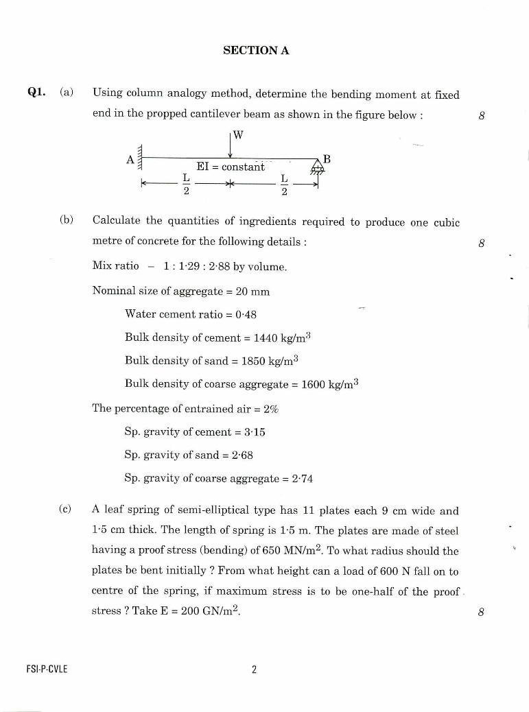
Ql. (a) Using column analogy method, determine the bending moment at fixed
end in the propped cantilever beam as shown in the figure below: 8
El = constant
>lc 2 2
Calculate the quantities of ingredients required to produce one cubic
metre of concrete for the following details : 8
Mix ratio — 1: 1.29 : 2.88 by volume.
Nominal size of aggregate = 20 mm
Water cement ratio = 0.48
Bulk density of cement = 1440 kg/m3
Bulk density of sand = 1850 kg/m3
Bulk density of coarse aggregate = 1600 kg/m3
The percentage of entrained air = 2%
Sp. gravity of cement = 3.15
Sp. gravity of sand = 2-68
Sp. gravity of coarse aggregate = 2.74
A leaf spring of semi-elliptical type has 11 plates each 9 cm wide and
1.5 cm thick. The length of spring is F5 m. The plates are made of steel
having a proof stress (bending) of 650 MN/m2. To what radius should the
plates be bent initially ? From what height can a load of 600 N fall on to
centre of the spring, if maximum stress is to be one-half of the proof.
stress ? Take E = 200 GN/m2. 8
FSI-P-CVLE 2
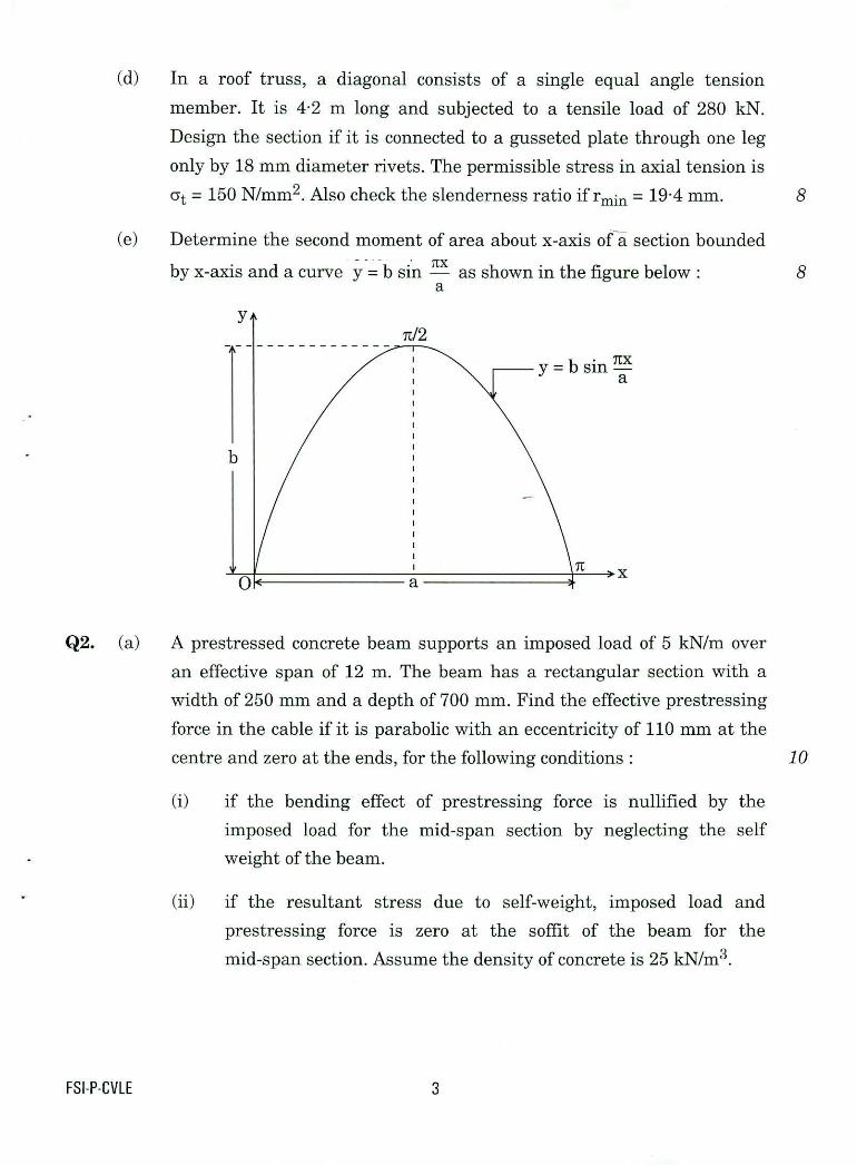
In a roof truss, a diagonal consists of a single equal angle tension
member. It is 4.2 m long and subjected to a tensile load of 280
Design the section if it is connected to a gusseted plate through one leg
only by 18 mm diameter rivets. The permissible stress in axial tension is
at = 150 N/mm2. Also check the slenderness ratio if rmin = 19.4 mm.
(e) Determine the second moment of area about x-axis of—a section bounded
by x-axis and a curve y= b sin — as shown in the figure below: a
Q2. (a) A prestressed concrete beam supports an imposed load of 5 kN/m over
an effective span of 12 m. The beam has a rectangular section with a
width of 250 mm and a depth of 700 mm. Find the effective prestressing
force in the cable if it is parabolic with an eccentricity of 110 mm at the
centre and zero at the ends, for the following conditions :
if the bending effect of prestressing force is nullified by the
imposed load for the mid-span section by neglecting the self
weight of the beam.
if the resultant stress due to self-weight, imposed load and
prestressing force is zero at the soffit of the beam for the
mid-span section. Assume the density of concrete is 25 kN/m3.
8
8
10
FSI-P-CVLE 3
(i)
A shaft is subjected to a maximum torque of 10 kNin and a maximum bending moment of 7.5 kNm at a particular section. If
the allowable equivalent stress in simple tension is 160 MN/m2, find the diameter of the shaft according to the maximum shear stress theory. 10
(ii) State maximum principal stress theory. 5
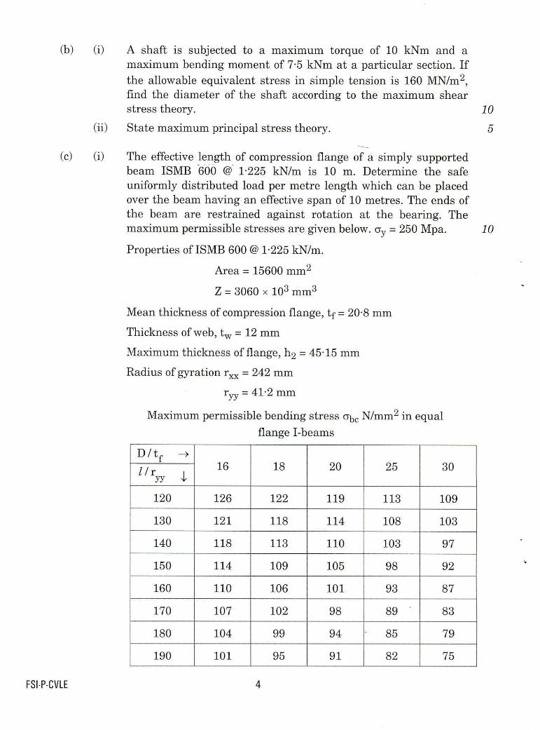
(i) The effective length of compression flange of a simply supported beam ISMB -600 @ 1.225 kN/m is 10 m. Determine the safe uniformly distributed load per metre length which can be placed over the beam having an effective span of 10 metres. The ends of the beam are restrained against rotation at the bearing. The maximum permissible stresses are given below. ay = 250 Mpa. /0
Properties of ISMB 600 @ F225 kN/m.
Area = 15600 mm2
Z = 3060 x 103 mm3
Mean thickness of compression flange, tf = 20.8 mm
Thickness of web, tw = 12 mm
Maximum thickness of flange, h2 = 45.15 mm
Radius of gyration r. = 242 mm
r = 4F2 mm YY
Maximum permissible bending stress abe N/mm2 in equal
flange I-beams
D / tf -4 16 18 20 25 30 / / ryy 4,
120 126 122 119 113 109
130 121 118 114 108 103
140 118 113 110 103 97
150 114 109 105 98 92
160 110 106 101 93 87
170 107 102 98 89 ' 83
180 104 99 94 85 79
190 101 95 91 82 75
FSI-P-CVLE 4

(ii) An RC wall of 200 mm thickness and 3.6 m effective height is
needed for a compressive load of 1250 kN. Design the wall using
M 15 grade of concrete and Fe 415 steel reinforcement.
Q3. (a) Draw the influence line diagram (ILD) for bending moment and shear
force for a section at 5 m from the left hand support of a simply
supported -beam, 20 m long. Hence calculate the maximum bending
moment and shear force at the section, due to uniformly distributed
rolling load of length 8 m and intensity 10 kNim run.
Design the vertical wall of a cantilever retaining wall to retain earth
embankment 4.5 m above ground level. The density of earth is 16 kN/m3
and its angle of repose is 30°. Top of the embankment is levelled one.
The safe bearing capacity of the soil may be taken as 210 kN/m2 and the
coefficient of friction between soil and concrete is 0.58. Adopt M 20 grade
concrete and Fe 415 grade steel.
A flywheel of diameter 0.7 m has a mass of 80 kg as shown in the figure
below. The coefficient of friction between the band and the flywheel is
0.40. If the initial rotating velocity of the flywheel is 400 rpm clockwise,
determine the magnitude of the force P required to stop the flywheel in
5 seconds.
5
10
15
15
FSI-P-CVLE 5
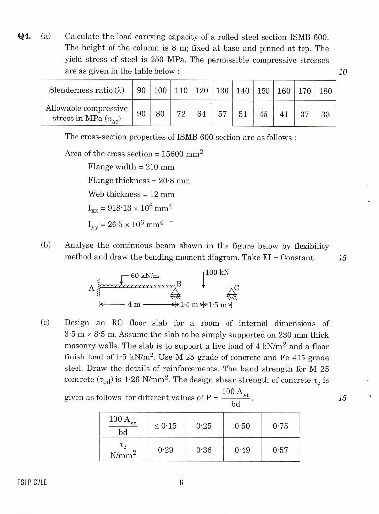
Q4. (a) Calculate the load carrying capacity of a rolled steel section ISMB 600.
The height of the column is 8 m; fixed at base and pinned at top. The
yield stress of steel is 250 MPa. The permissible compressive stresses
are as given in the table below: 10
Slenderness ratio (X) 90 100 110 120 130 140 150 160 170 180
Allowable compressive stress in MN. (ccad
90 80 72 64 57 51 45 41 37 33
The cross-section properties of ISMB 600 section are as follows :
Area of the cross section = 15600 mm2
Flange width = 210 mm
Flange thickness = 20.8 mm
Web thickness = 12 mm
= 91813 x 106 mm4
I = 26.5 x 106 mm4 - YY
Analyse the continuous beam shown in the figure below by flexibility
method and draw the bending moment diagram. Take El = Constant. 15
1100 kN
AC
1g-- 4m
+1 5 m+1-5 m->1
Design an RC floor slab for a room of internal dimensions of
3.5 m x 8.5 m. Assume the slab to be simply supported on 230 mm thick
masonry walls. The slab is to support a live load of 4 kN/m2 and a floor finish load of 1.5 kN/m2. Use M 25 grade of concrete and Fe 415 grade
steel. Draw the details of reinforcements. The band strength for M 25 concrete (Tbd) is 1.26 N/mm2. The design shear strength of concrete te is
given as follows for different values of P = 100A
bd 15
100 Ast < 015 0.25 0.50 0.75 bd
-cc 2 N/mm
0.29 0.36 0.49 0.57
FSI-P-CVLE 6
SECTION B
Q5. (a) What are important clay minerals ? Why do clays exihibit plasticity? 8
(b) A granular soil was tested in the laboratory and found to have maximum
and minimum void ratios of 0.82 and 0.38 respectively. The specific
gravity of soil solids was 2.66. A natural deposit of the same soil has 10%
moisture and its moist unit weight is 19 kN/m3. Determine the-relative
density of the soil in the field. 8
(c) What are the merits and demerits of the stone column method of soil
improvement? 8
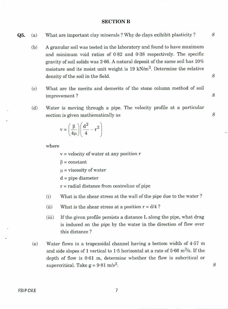
(d) Water is moving through a pipe. The velocity profile at a particular
section is given mathematically as 8
V = 1) (12
— r2 \
4
where
v = velocity of water at any position r
13 = constant
= viscosity of water
d = pipe diameter
r = radial distance from centreline of pipe
What is the shear stress at the wall of the pipe due to the water?
What is the shear stress at a position r = d/4?
If the given profile persists a distance L along the pipe, what drag
is induced on the pipe by the water in the direction of flow over
this distance ?
(e) Water flows in a trapezoidal channel having a bottom width of 4.57 m
and side slopes of 1 vertical to 1-5 horizontal at a rate of 5.66 m3/s. If the
depth of flow is 0.61 m, determine whether the flow is subcritical or
supercritical. Take g = 9.81 m/s2.
FSI-P-CVLE 7

0
Eff
ecti
ve
overb
urd
en s
tress
, kN
/m2
100
200
300
400
500
Q6. (a) An SPT test was conducted in a sand deposit at 12 m depth. The unit
weight of sand is 20 kN/ra3 and water table is at 2 m below natural
ground surface. If the observed SPT value is 24; what will be the
corrected N value ? Use the figure below to apply overburden correction. 10
Correction factor CN
0 2 0.4 0.6 0 8 1.0 1.2 1.4 1.6 1.8 2.0
Correction factor for N-values for overburden correction
(b) Forest areas usually have freshwater ponds and lakes in which small
animals such as crayfish, shrimp, etc. live. One such animal has an
average diameter of 1 mm. We want to know the drag force on this
animal when it moves slowly in freshwater. As it is difficult to measure
this drag force on such a small animal, a scale model 100 times larger is
made and tested in glycerin in a laboratory at V = 30 cm/s. The
measured drag on the model is 1.3 N. For similar conditions, find the
velocity and drag of the actual animal in water. Given that
15
Pwater = 0.001 kg/(m-s) Pwater = 999 kghla3
Pglycerin = F5 kg/(m-s) pey„rin = 1263 kg/m3
FSI-P-CVLE 8
(c) (i) Sketch the general layout of a hydropower system with a reaction
turbine.
(ii) A reaction turbine is supplied with water through a 150 cm pipe
(penstock) (e = 1.0 mm) that is 40 m long. The water surface in
the reservoir is 20 m above the draft tube inlet, which is 4-5 m
above the water level in the tailrace. If the turbine efficiency is
92% and the discharge is 12 m3/s, what is the power output of the
turbine in kilowatts ? Use f= 0.0185, g = 9.81 m/s2. 15
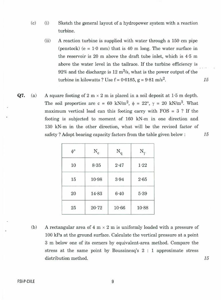
Q7. (a) A square footing of 2 m x 2 m is placed in a soil deposit at 1.5 m depth.
The soil properties are c = 60 kN/m2, = 22°, y = 20 kN/m3. What
maximum vertical load can this footing carry with FOS = 3 ? If the
footing is subjected to moment of 160 kN-m in one direction and
130 kN-m in the other direction, what will be the revised factor of
safety ? Adopt bearing capacity factors from the table given below: 15
4? Ne Nq N Y
10 8.35 2.47 1.22
15 10-98 3.94 2.65
20 14.83 6-40 5-39
25 20.72 10.66 10.88
(b) A rectangular area of 4 m x 2 m is uniformly loaded with a pressure of
100 kPa at the ground surface. Calculate the vertical pressure at a point
3 m below one of its corners by equivalent-area method. Compare the
stress at the same point by Boussinesq's 2 : 1 approximate stress
distribution method. 15
FSI-P-CVLE 9
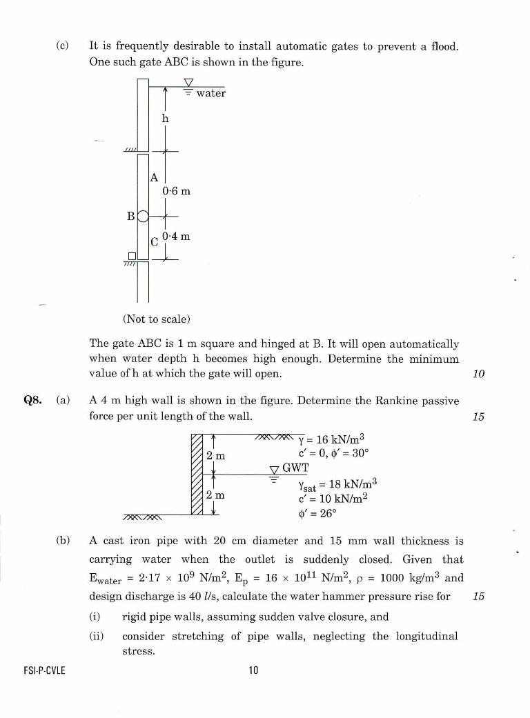
(c) It is frequently desirable to install automatic gates to prevent a flood.
One such gate ABC is shown in the figure.
A 0.6 m
04m
(Not to scale)
The gate ABC is 1 m square and hinged at B. It will open automatically when water depth h becomes high enough. Determine the minimum value of h at which the gate will open. 10
Q8. (a) A 4 m high wall is shown in the figure. Determine the Rankine passive
force per unit length of the wall. 15
y= 16 kN/m3 c' = 0, 0' = 30°
GWT
?sat = 18 kN/1113 c'= 10 kN/m2 0' = 26°
(b) A cast iron pipe with 20 cm diameter and 15 mm wall thickness is
carrying water when the outlet is suddenly closed. Given that
Ewater = 217 x 109 N/m2, Ep = 16 x 1011 N/m2, p = 1000 kg/m3 and
design discharge is 40 Us, calculate the water hammer pressure rise for 15
(i) rigid pipe walls, assuming sudden valve closure, and
consider stretching of pipe walls, neglecting the longitudinal stress.
FSI-P-CVLE 10

vena contracta
(c)
Consider a vertical sluice gate in a wide rectangular channel. The depth of
flow at the vena contracta is 0-457 m for a flow rate of 4.646 m3/s per
metre of width. The channel bed slope is 0.0003 and Manning's roughness
factor is n = 0.020. The depth of flow at point b is 0-5 m.
Determine whether a jump occurs.
What is the type of water surface profile? /0
Take g = 9.81 m/s2.
FSIT-CVLE 11

.