Ifm Innovations English 2013-2014
103
www.ifm.com Innovations 2013/2014
-
Upload
ifm-electronic-gmbh -
Category
Business
-
view
397 -
download
6
description
Ifm Innovations 2013-2014
Transcript of Ifm Innovations English 2013-2014

ww
w.if
m.c
om
Innovations 2013/2014

3
IO-Link sensor for position and level detection
Capacitive sensors
Photoelectric sensors for general applications
High-performance “O6 wetline” photoelectric sensors (11.2013)
(11.2013)
Position sensors
Laser sensors / distance measurement sensors
First standard photocell with time of flight measurementPhotoelectric sensor with time of flight measurement and easy-turn
(04.2013)
(04.2013)
Temperature sensors
Infrared temperature sensor with display / operating unit on the sensorTemperature transmitter with display and IO-Link
A quantum leap in flow rate measurement technology (11.2013)
Flow sensors / flow meters
(11.2012)
(11.2013)
Process sensors
Online vibration monitoring according to ISO 10816
Vibration monitoring systems
(11.2012)
Condition monitoring systems
3.3 to 20 A with high efficiency in a slim design
24 V DC power supplies
(04.2013)
2.8 to 8 A with high efficiency in a slim design
AS-i power supplies
(04.2013)
Power supplies
TOP
PRO
DU
CTS
Precision for all inclinations
Inclination sensors
(11.2013)
Sensors for motion control
Powerful 32-bit SafetyController for mobile machines
Safety controllers
(04.2013)
Safety technology
4 - 5
6 - 9
10 - 1112 - 13
16 - 17
20 - 2122 - 23
18- 19
24 - 25
26 - 27
28 - 29
14 - 15

4
Position sensors
IO-Link sensor for positionand level detection
New featuresFor this new product line, the existing capacitive sensorswere enhanced with IO-Link. All further data as well asthe order numbers remain the same.
ApplicationCapacitive sensors detect bulk materials or liquidsthrough non-metallic vessel walls. Typical applicationsfor product detection can be found in the semiconduc-tor, paper and wood industries.
Parameter settingThe parameters can either be set via the buttons on thesensor or via IO-Link interface. This can be done usingthe USB interface E30396 or a memory plug.
Data transmissionA standard M12 cable transmits process data, parame-ters and diagnostic information to a connected IO-Linkmaster. When IO-Link is not in use, the sensor workswith one switching output.
Easy parameter setting via IO-Link beforeinstallation of the sensor
Versatile data processing via IO-Link
Normally open / normally closed freelyselectable
Clearly visible indication of the switchingstatus
Easy installation with mounting adaptersand cable ties
The first capacitive sensor with IO-Link

5
11.2013
TOP
PRO
DU
CTS
For further technical data please go to: www.ifm.com
Position sensorsCapacitive sensors
Type Description Order no.
Accessories
Mounting adapter for free-standing mounting, PBT E12153
Mounting adapter for pipe and tubemounting with cable ties, PA E12163
Connection technology
Type Description Order no.
M12 socket,2 m black, PUR cable EVC001
M8 socket,2 m black, PUR cable EVC150
* automatic detection of the load
Memory plug, parameter memory for IO-Link sensors E30398
IO-Link interface, current consumption from USB port E30396
LINERECORDER SENSOR,software for parameter setting and set-up of IO-Link sensors
ZGS210
Type
[mm]
Output stage
Housing material Protection rating / class
Order no.
Connection cable 2 m PVC· 3 wires
M18 x 1 PNP / NPN* PP, TPE-U IP 65, IP 67, II KG5067
M18 x 1 PNP PP, TPE-U IP 65, IP 67, II KG5069
Connection cable with M8 connector · 3 wires
48 x 20 x 14 PNP / NPN* PBT, PC, TPE-U IP 65, IP 67, III KQ6003
48 x 20 x 14 PNP PBT, PC, TPE-U IP 65, IP 67, III KQ6004
Connection cable with M12 connector · 3-wire
48 x 20 x 14 PNP
Setting range[mm]
2...14
2...14
3...20
3...20
48 x 20 x 14 PNP PBT, PC, TPE-U IP 65, IP 67, III KQ60083...20
48 x 20 x 14
Communicationinterface
IO-Link 1.1
IO-Link 1.1
48 x 20 x 14 PNP / NPN* PBT, PC, TPE-U IP 65, IP 67, III KQ6001
48 x 20 x 14 PNP PBT, PC, TPE-U IP 65, IP 67, III KQ6002
3...20
3...20
IO-Link 1.1
IO-Link 1.1
M12 connector · 3 wires
M18 x 1 PNP / NPN* PBT, PC, TPE-U IP 65, IP 67, II KG5065
M18 x 1 PNP PBT, PC, TPE-U IP 65, IP 67, II KG5066
4...24
4...24
IO-Link 1.1
IO-Link 1.1
M18 x 1 PNP PBT, PC, TPE-U IP 65, IP 67, II KG5071
M30 x 1.5 PNP / NPN* PBT, PC, TPE-U IP 65, IP 67, II KI5082
2...14
5...40
IO-Link 1.1
IO-Link 1.1
M30 x 1.5 PNP PBT, PC, TPE-U IP 65, IP 67, II KI5083
M30 x 1.5 PNP / NPN* high-grade stainless steel(1.4404), TPE-U, PBT, PEI IP 65, IP 67, III KI5084
5...40
2...12
IO-Link 1.1
IO-Link 1.1
M30 x 1.5 PNP high-grade stainless steel(1.4404), TPE-U, PBT, PEI IP 65, IP 67, III KI5085
M30 x 1.5 PNP / NPN* high-grade stainless steel(1.4404), TPE-U, PBT, PEI IP 65, IP 67, III KI5086
2...12
3...26
IO-Link 1.1
IO-Link 1.1
M30 x 1.5 PNP high-grade stainless steel(1.4404), TPE-U, PBT, PEI IP 65, IP 67, III KI50873...26 IO-Link 1.1
IO-Link 1.1
IO-Link 1.1
IO-Link 1.1
IO-Link 1.1
IO-Link 1.1PNP PBT, PC, TPE-U IP 65, IP 67, III KQ60103...20
3...20 PBT, PC, TPE-U IP 65, IP 67, III KQ6005

6
Tiny yet powerful photocellsfor the food industry
Best optical performanceThe diffuse reflection sensors distinguish themselves byreliable background suppression, even in case of highlyreflective backgrounds. The sensing range is independent of the characteristics and colour of the object to be detected. A special feature is the automatic sensitivitycompensation that guarantees reliable operation evenin steam, smoke or highly reflective environments.
Ideal for food applicationsThe potentiometers are provided with a double sealand are, like the front pane, embedded flush to allowresidue-free cleaning. The transparent black housingcover ensures that, even in bright lighting conditions,the LEDs are highly visible. The coated front pane ismade of resistant, shatterproof plastic.
Stainless steel housing with protection rating IP 68 / IP 69K
Easy adjustment via potentiometer
Diffuse reflection sensors with reliablebackground suppression
Object colour has no influence on therange
Also available as through-beam or retro-reflective system
High-performance “O6 wetline”photoelectric sensors
Position sensors

7
TOP
PRO
DU
CTS
Infrared sensors / red light sensors
Diffuse reflection sensor with background suppression · PVC cable, 2 m · 3-wire DC
Light spot diameter
[mm]
Light-on / dark-on mode
Current consumption
[mA]
Order no.
8* O6H300
Range
[mm]
2...200 adjustable 20
Switching frequency
[Hz]
1000
Order no.
O6H304
Position sensors
PNPNPN
Diffuse reflection sensor with background suppression · M12 connector with 0.3 m PVC cable · 3-wire DC
8* O6H3012...200 adjustable 20 1000 O6H305
PNPNPN
Diffuse reflection sensor · PVC cable, 2 m · 3-wire DC
15* O6T3005...500 adjustable 20 1000 O6T304
PNPNPN
Diffuse reflection sensor · M12 connector with 0.3 m PVC cable · 3-wire DC
15* O6T3015...500 adjustable 20 1000 O6T305
PNPNPN
Retro-reflective sensor with polarisation filter · PVC cable, 2 m · 3-wire DC
150** O6P30050...5000 adjustable 20 1000 O6P304
PNPNPN
Retro-reflective sensor with polarisation filter · M12 connector with 0.3 m PVC cable · 3-wire DC
150** O6P30150...5000 adjustable 20 1000 O6P305
PNPNPN
Through-beam sensor transmitter · PVC cable, 2 m · 2-wire DC
300*0...10000 – 20 – O6S300
Through-beam sensor transmitter · M12 connector with 0.3 m PVC cable · 2-wire DC
300*0...10000 – 20 – O6S301
Through-beam sensor receiver · PVC cable, 2 m · 3-wire DC
– O6E3000...10000 adjustable 20 1000 O6E304
PNPNPN
Through-beam sensor receiver · M12 connector with 0.3 m PVC cable · 3-wire DC
– O6E3010...10000 adjustable 20 1000 O6E305
PNPNPN
* at maximum range** referred to prismatic reflector Ø 80 mm
Dimensions
2 x LED
1321
34,8
25,4
2,8
3
M3
LED
1321
34,8
25,4
2,8
3
M3
L+
L
1
4
3
Wiring diagram
L+
L
1
4
3
BN
BK
BU
L+
L L
BN
BK
BU
L+
L+
L
BN
BU
1
3
L+
L

8
Position sensors
Diffuse reflection sensor with background suppression · M8 connector 3-pole · 3-wire DC
8* O6H3022...200 adjustable 20 1000 O6H306
PNPNPN
Diffuse reflection sensor with background suppression · M8 connector 4-pole · 3-wire DC
8* O6H3032...200 adjustable 20 1000 O6H307
PNPNPN
Diffuse reflection sensor · M8 connector 3-pole · 3-wire DC
15* O6T3025...500 adjustable 20 1000 O6T306
PNPNPN
Diffuse reflection sensor · M8 connector 4-pole · 3-wire DC
15* O6T3035...500 adjustable 20 1000 O6T307
PNPNPN
Retro-reflective sensor with polarisation filter · M8 connector 3-pole · 3-wire DC
150** O6P30250...5000 adjustable 20 1000 O6P306
PNPNPN
Retro-reflective sensor with polarisation filter · M8 connector 4-pole · 3-wire DC
150** O6P30350...5000 adjustable 20 1000 O6P307
PNPNPN
Through-beam sensor transmitter · M8 connector 3-pole · 2-wire DC
300*0...10000 – 20 – O6S302
Through-beam sensor transmitter · M8 connector 4-pole · 2-wire DC
300*0...10000 – 20 – O6S303
Through-beam sensor receiver · M8 connector 3-pole · 3-wire DC
– O6E3020...10000 adjustable 20 1000 O6E306
PNPNPN
Through-beam sensor receiver · M8 connector 4-pole · 3-wire DC
– O6E3030...10000 adjustable 20 1000 O6E307
PNPNPN
* at maximum range** referred to prismatic reflector Ø 80 mm
Dimensions
2 x LED
M8x1
1321
34,8
25,4
2,8
3
41,3
M3
LED
M8x1
1321
34,8
25,4
2,8
3
41,3
M3
L+
L
1
4
3
Wiring diagram
L+
L
1
4
3
1
3
L+
L
Light spot diameter
[mm]
Light-on / dark-on mode
Current consumption
[mA]
Order no.
Range
[mm]
Switching frequency
[Hz]
Order no.

9
11.2013
TOP
PRO
DU
CTS
For further technical data please go to: www.ifm.com
Infrared sensors / red light sensorsPosition sensors
Common technical data
Operating voltage [V DC] 10...30
Type of light red light 633 nm
Switching status indication LED yellow
Operation LED green
Protection rating, class
IP 65, IP 67, IP 68, IP 69KIII
Short-circuit protection, pulsed •
Reverse polarity protection / overloadprotection • / •
Ambient temperature [°C] -25...80
Voltage drop [V] < 2.5
Current rating [mA] 100
Accessories
Type Description Order no.
Mounting set for clamp mounting,stainless steel E21272
Bracket for free-standing mounting,stainless steel E21271
Protective bracket,stainless steel E21273
18 x 18 mm, Solidchem plastic E21267
56 x 38 mm, Solidchem plastic E21268
48 x 48 mm, Solidchem plastic E21269
96 x 96 mm, Solidchem plastic E21270
Materials housing
lens
high-grade stainless steel(1.4404 / 316L)
PPSU PMMA
Prismatic reflectors for the food industry (up to 140 °C)
Connection technology
Type Description Order no.
Socket, M8,2 m orange, PVC cable EVT122
Socket, M8,5 m orange, PVC cable EVT123
Socket, M8,2 m orange, PVC cable EVT126
Socket, M8,5 m orange, PVC cable EVT127
Socket, M8,2 m orange, PVC cable, LED EVT130
Socket, M8,5 m orange, PVC cable, LED EVT131
Mounting rod, 120 mm, Ø 10 mm, M8 thread, stainless steel E21081
Angle bracket for reflector E21269, stainless steel E20724
Mounting set for reflector E21270, clamp mounting, stainless steel E20935
Socket, M12, 4-pole,5 m orange, PVC cable EVT001
Socket, M12, 4-pole,2 m orange, PVC cable EVT064
Socket, M12, 4-pole,5 m orange, PVC cable EVT004
Socket, M12, 4-pole,2 m orange, PVC cable EVT067

10
O5D with display – first standard photocell with timeof flight measurement (PMD)
Time of flight measurement for standard sensorsThe O5D with time of flight measurement (PMD = photonic mixer device) combines the following advan-tages: long ranges, reliable background suppression, visible red light and high excess gain. In the same pricerange as standard sensors, it is a clever alternative.
Easy handlingThe switch point is set easily to the nearest centimetrevia “+/-” buttons and display or alternatively via IO-Link, which also allows read-out of the actual value.
Any surface and any mounting positionShiny, matt, dark or light objects of any colour: the O5D features reliable background suppression. The unit allows any angle of incidence and thus flexible mountingpositions. This simplifies installation and saves costs.
Reliable background suppression and colour-independent detection
Precise time of flight measurement in hous-ing sizes of standard photoelectric sensors
Shiny surfaces are detected reliably (e.g. stainless steel)
Any sensor position, even an obliqueangle to the object
Switch point setting to the nearest centimetre via “+/-” buttons and display
PMDLine series – a new generationof photoelectric sensors
Position sensors

11
04.2013
TOP
PRO
DU
CTS
For further technical data please go to: www.ifm.com
Laser sensors / distance measurement sensors
Common technical data
Operating voltage [V DC] 10...30
Dimensions [mm] 56 x 18,2 x 46,5
Type of light visible laser light 650 nm
Extraneous light on the object [klx] max. 8
Switching status indication LED yellow
Operation LED green
Distance value3-digit
alphanumeric display
Protection rating, protection class
IP 65,IP 67II
Short-circuit protection, pulsed •
Reverse polarity protection / overload protection • / •
Ambient temperature [°C] -25...60
Current rating [mA] 2 x 100
Output function OUT1: NOOUT2: NC
Position sensors
Connection technology
Type Description Order no.
Socket, M12,2 m black, PUR cable EVC001
Socket, M12,5 m black, PUR cable EVC002
Socket, M12,2 m black, PUR cable EVC004
Socket, M12,5 m black, PUR cable EVC005
Photoelectric distance sensor, laser protection class 2 · M12 connector, complementary
30...2000 < 5 < 75 O5D101
30...2000 O5D100< 5 < 75 cm
inch
Material housing / plug adapterfront pane / LED window
bezeloperator interface
PAPMMA
stainless steelTPU
Accessories
Type Description Order no.
Mounting bracket for rod,complete set incl. clamp E21083
Protective bracket for rod,complete set incl. clamp E21084
Universal angle bracket E21085
Bracket for free-standing mounting E21087
Dovetail clamp E21088
Rod, 100 mm, Ø 12 mm,M10 thread, stainless steel E20938
Cube for mounting on an aluminiumprofile, M10 thread, diecast zinc E20951
Measuringrange[mm]
Backgroundsuppression
[m]
Switching frequency
[Hz]
Spot Ø at max. range
[mm]
Current consumption
[mA]
Order no.
Unit of measurement
Hysteresis
[%]
Memory plug, parameter memory for IO-Link sensors E30398
IO-Link interface, current consumption from USB port E30396
LINERECORDER SENSOR, software for parameter setting and set-up of IO-Link sensors
ZGS210
* black (6 % remission) in case of max. range
...20 11
...20 11
< 6*
< 6*

12
OID with easy-turn concept –photoelectric sensor with timeof flight measurement (PMD)
Time of flight measurement for standard sensorsThe OID with time of flight measurement (PMD = photonic mixer device) combines the following advan-tages: long ranges, reliable background suppression, visible red light and high excess gain. In the same pricerange as standard sensors, it is a clever alternative.
Easy handlingThe switch point can be set easily by turning the settingring (easy turn). A scale shows the distance set. Theswitch point can thus be set before installation.
Any surface and any mounting positionShiny, matt, dark or light objects of any colour: the OID features reliable background suppression. The unit allows any angle of incidence and thus flexible mountingpositions. This simplifies installation and saves costs.
Reliable background suppression and colour-independent detection
Simple switch point setting by rotatablesetting ring (lock function)
Shiny surfaces are detected reliably (e.g. stainless steel)
Any sensor position, even an obliqueangle to the object
IO-Link integrated, e.g. for reading theactual value
PMDLine M30: This photoelectricsensor is all set
Position sensors

13
04.2013
TOP
PRO
DU
CTS
For further technical data please go to: www.ifm.com
Laser sensors / distance measurement sensors
Common technical data
Operating voltage [V DC] 10...30
Dimensions M30 x 90 mm
Type of light visible laser light 650 nm
Extraneous light on the object [klx] max. 8
Switching status indication LED yellow
Operation LED green
Switch point (setting) radial setting ring
Protection rating, protection class
IP 65,IP 67III
Short-circuit protection, pulsed •
Reverse polarity protection / overload protection • / •
Ambient temperature [°C] -25...60
Current rating [mA] 2 x 100
Output function OUT1: NOOUT2: NC
Position sensors
Connection technology
Type Description Order no.
Socket, M12,2 m black, PUR cable EVC001
Socket, M12,5 m black, PUR cable EVC002
Socket, M12,2 m black, PUR cable EVC004
Socket, M12,5 m black, PUR cable EVC005
Photoelectric distance sensor, laser protection class 2 · M12 connector, complementary
Measuringrange[mm]
Backgroundsuppression
[m]
Switching frequency
[Hz]
Spot Ø at max. range
[mm]
Current consumption
[mA]
Order no.
Unit of measurement
Hysteresis
[%]
Material housing
front pane
stainless steel, PBT, PC, FPM
PMMA
Rod, 100 mm, Ø 12 mm,M10 thread, stainless steel E20938
Cube for mounting on an aluminiumprofile, M10 thread, diecast zinc E20951
Type Description Order no.
Accessories
Angle bracket for type M30,stainless steel E10737
Mounting clamp for types M30, PTB E10077
Mounting set Ø 30.2 mm, clamp mounting, aluminium profile E20875
Mounting set Ø 30.2 mm, clamp mounting E20873
Mounting set Ø 30.2 mm, clampmounting, high-grade stainless steel E20874
Mounting clamp, with end stop for types M30, PC E11049
Memory plug, parameter memory for IO-Link sensors E30398
IO-Link interface, current consumption from USB port E30396
LINERECORDER SENSOR, software for parameter setting and set-up of IO-Link sensors
ZGS210
30...2000 < 5 < 75 OID201
30...2000 OID200< 5 < 75 cm / inch
cm
* black (6 % remission) in case of max. range
...20 11
...20 11
< 5*
< 5*

14
Sensor for precise measure-ment of angles of inclinationon X and Y axes
Precise in all positionsThe new ifm type JN inclination sensors provide highmeasurement accuracy across the whole angular rangewith angles of inclination in X and Y axes. The 2-axis inclination sensors with CANopen interfaceand bus capability are designed for levelling of mobilemachinery (2-axis position detection and zero-pointlevelling for mobile applications) or automatic adjustment of solar panels, for example.
High precision across the total angularrange in two axes
Zero point, counting direction and limitfrequency adjustable
Extremely low temperature drift (± 0.002 °/K)
M12 connector, CAN in and CAN out
Fully CAN-compatible
Precision for all inclinations
Sensors for motion control

15
11.2013
TOP
PRO
DU
CTS
Operating voltage [V DC] 10...30 DC
Reverse polarity protection •
Angular rangeResolutionAccuracyRepeatability
JN2100± 180°0.05°
≤ ± 0.5°≤ ± 0.1°
JN2101± 45°0.01°± 0.1°
≤ ± 0.05°
Ambient temperature [°C] -40...85
Temperature coefficient [°/K] ≤ ± 0.002°
Protection IP 65 / IP 68 / IP 69K
Interface
CANopen CiA DS 301 / device profile CiA DSP-410
Limit frequency [Hz] Adjustable: 20, 10, 5, 1, 0.5
Number of measurement axes 2
Housing material Diecast zinc nickel-plated
Connection 2 x M12 connector
Technical dataJN2100, JN2101
Inclination sensors
Connection technology
Type Description Order no.
Socket, M12,2 m black, PUR cable EVM039
Socket, M12,10 m black, PUR cable EVM041
Socket, M12,2 m black, PUR cable EVM036
Socket, M12,10 m black, PUR cable EVM038
Accessories
Description Order no.
Adapter cable for CAN devices with M12 connector (5 pole) EC2062
Dimensions
364,
5
90753
224560
3
Flexible, precise, reliableSince zero point, direction of counting (+/-180° or0...360°) and limit frequency can be set for a stableoutput signal (20, 10, 5, 1, 0.5 Hz), this innovativeproduct can be adapted precisely to your application.Very low temperature drift across the whole tempera-ture range (-40...85 °C) provides unrivalled reliability.
Ideal for different applicationsThe sensors allow complete CAN integration according to the CANopen CiA DS-301 communication profilesand profile CiA DSP-410. They are connected via an M12 connector. The terminating resistor can be enabled. In addition, thesensors have an E1 approval and provide the signalsas angle to the vertical or Euler angle.
Type
Sensors for motion control
For further technical details please visit: www.ifm.com
Jumper, M12,5 m, black, PUR cable EVC069
Jumper, M12,5 m, black, PUR cable EVC059

16
Powerful 32-bit SafetyController with TÜV approval
Sophisticated safety conceptifm electronic offers a new, powerful 32-bit safety controller for safety-related applications in mobile machines. The device is the perfect choice for complexand demanding control functions.The 32-bit SafetyController has been developed to current safety standards. Hardware and software havebeen certified by the German TÜV association.What is new is the programmable, layered error han-dling (keep alive): the SafetyController can be used sothat if there is a serious fault it brings the plant intosafe state before shutting down. In case of less seriouserrors however, parts of the plant in previously definedareas can still be used. Not all components have to beswitched off.The behaviour of the inputs and outputs can be adapted to the application easily and precisely usingthe CODESYS programming software.
Safety controller to EN 13849 PL d, EN 62061 SIL cl2 and IEC 61508
Layered safety concept, extended monitoring and test routines
Safe inputs and outputs with configurablebehaviour in case of a fault
Fast bootup and short error detection time
CAN interfaces with CANopen, CANsafetyand SAE J1939 protocol
Certified safety for mobile machines
Safety technology

17
04.2013
TOP
PRO
DU
CTS
For further technical data please go to: www.ifm.com
Safety controllers
Technical data
Advantages and customer benefits
• Developed to current safety standardsAlmost all mobile machines have functions that mayendanger persons and equipment. There are clearlydefined product standards for more and more appli-cations (e.g. vehicle lifts, refuse trucks). The revisedMachinery Directive often means that the machinemanufacturers have to meet new requirements.The 32-bit SafetyController can be used in applicationsup to EN 13849 PL d and EN 62061 SIL cl2. Hardwareand software of the SafetyController have moreoverbeen certified by TÜV.
• The safety conceptThe safety concept monitors all internal and externalfunctions and reliably switches off in case of an error.Special test routines for hardware and software moni-toring are implemented in the devices. Nevertheless,these devices are easy and convenient to program via CODESYS. Diagnostic information can be founddirectly in the application. The behaviour of the out-puts can be configured via the software in case of afault (keep alive). Hardware, operating system software and the pro-gramming tools are certified. This simplifies approvalof the project developer’s machine, because he onlyneeds to focus on his application program.
• PowerfulDue to 32-bit technology, the powerful Safety-Controller is ideally suited for complex control tasks.Proportional functions are quickly processed. The fastbootup and the short error detection time of 110 msprovide sufficient safety in the application.
• ConfigurabilityAnalogue, digital and frequency ports are available as safety-related inputs and outputs. Furthermore,fail-safe inductive sensors can be connected to theSafetyController. The safe and non-safe outputs canbe used as digital and PWM outputs.
• CANsafetyIn addition to the CANopen profile, CANsafety (DS 304) enables a safe data exchange between bus participants on the same bus cable while the“normal” communication is in process between CAN bus participants (e.g. I/O modules). Each SafetyController supports up to four safe transmit or receive objects (SRDO). The data is safely processedvia the two integrated CAN interfaces.
Safety technology
Description Order no.
SafetyController, 32 bits, 16 I / 16 O CR7032
SafetyController, 32 bits, 32 I / 48 O CR7132
Connector, 55 poles (wirable) EC2013
Cable with connector 55 poles, 1.2 m EC2086
Programming cable with USB adapter, 2 m EC2096
Programming software CODESYS, German V2.3 CP9006
Programming software CODESYS, English V2.3 CP9008
Products
SafetyController
Housing closed metal housing withflange fastening
Device connectionAMP connector
55 poles latched, protectedagainst reverse polarity
Protection IP 67
Operating voltage [V DC] 8...32
Current consumption [mA](CR7032 / CR7132) ≤ 160 / 320
Temperature range [°C] -40...85
Indicators RGB LED
Controller Infineon TriCore 1796
Inputs (total) digital (positive / negative)analogue (0...10 / 32 V, 0...20 mA)frequency (≤ 30 kHz)
CR703216
CR713232
Outputs (total)digital, high-side/low-side, H-bridge (2/4 A)digital, PWM, current-controlled (2/4 A)digital, PWM, current-controlled (2 A)digital, (2 A)
16448
48881616
Voltage output5 / 10 V DC, 400 mA 1
Interfaces4 x CAN
1 x RS 2321 x virt. COM port (USB)
Supported CAN protocols
CANopen(CiA DS 301 V4.01)
and DSP 306SAE J 1939
Program memory [MB] 1.25
Data memory RAM [kB] 256
Data memory non-volatile [kB]Auto save 56 (4)
Programming software CODESYS V2.3
Safety-related characteristicsIEC 62061 SIL cl2ISO 13849-1 PL d
DC 90...99 %
Standards and tests (extract)CE,
E1 (UN/ECE R10),EN 50 155

18
Inline flow sensor for precisemeasurement of liquids up to600 l/min
Magnetic-inductive volumetric flow sensor formeasuring the water quantity in a filtration system.
Compact and low costifm makes it possible: efector mid – a volumetric flowsensor up to 600 l/min, with electronics and evaluationunit in one of the most compact housings. It is not onlymore compact but also less expensive than comparablesensors.
Three functionsThe user monitors the volumetric flow quantity, thetotal quantity as well as the temperature with only oneunit.
Easy handlingDuring set-up, the efector mid scores with easy, intuitive handling via three buttons directly on the unit.This allows direct use of the sensor in the field.
Data processingAnalogue, binary and pulse and frequency outputsoffer various options to process the measured data.
Suited for liquids with a conductivityfrom 20 μS/cm
Variable use for different flow directions
With integrated empty pipe detectionand simulation mode
Also available with EPDM seal for drinking water applications
With indication of volumetric flow quantity, total quantity and temperature
A quantum leap in flow ratemeasurement technology
Process sensors

19
11.2013
TOP
PRO
DU
CTS
Flow sensors / flow meters
Application: Machine tools, solar and water industries.For conductive liquids (conductivity: ≥ 20 μS/cm / viscosity: < 70 mm2/s at 40 °C)
Measuring rangeFlow
[l/min / gpm]
Pulse value
[l...m3]
Response timeFlow
[s]
AccuracyFlow
Process connection Orderno.
M12 connector · electrical design DC PNP/NPN · FKM seal
5...300 0.1...300,000 < 0.35 (dap = 0) ± (0.8 % MV + 0.5 % VMR) G 2 SM9000
5...600 0.1...600,000 < 0.35 (dap = 0) ± (0.8 % MV + 0.5 % VMR) G 2 SM2000
M12 connector · electrical design DC PNP/NPN · EPDM seals
SM9100
SM2100
Further technical data
Operating voltage [V] 18...32 DC
Current consumption [mA] < 150
Short-circuit protection, pulsed •
Housing materials
high-grade stainless steel(316L/1.4404);
PC (polycarbonate);FKM; PBT-GF20
Materials (wetted parts)
PEEK Victrex 150 GL30,high-grade stainless steel
(316Ti/1.4571),Hastelloy (2.4610), FKM,
Centellen
Protection IP 65, IP 67
Output function OUT1SM9000, SM2000SM9100, SM2100
OUT2
normally open / normallyclosed programmable or
pulse or frequency orempty pipe monitoring
or IO-Link
normally open / normallyclosed programmable
or analogue(4...20 mA / 0...10 V,
scalable) or empty pipemonitoring
Ambient temperature [°C] -10...60
Medium temperature [°C] -10...70
Pressure resistance [bar] 16
Reverse polarity / overload protection • / •
Measuring range temperature [°C] -20...80
TypeSM
Connection technology
Type Description Orderno.
M12 socket,2 m black, PUR cable EVC001
M12 socket,5 m black, PUR cable EVC002
M12 socket,2 m black, PUR cable EVC004
M12 socket,5 m black, PUR cable EVC005
Current rating [mA]SM9000, SM2000SM9100, SM2100
2 x 250
5...300 0.1...300,000 < 0.35 (dap = 0) ± (0.8 % MV + 0.5 % VMR) G 2
5...600 0.1...600,000 < 0.35 (dap = 0) ± (0.8 % MV + 0.5 % VMR) G 2
For further technical data please go to: www.ifm.com
Process sensors
Accessories
Type Description Order no.
Memory plug, parameter memory for IO-Link sensors E30398
Adapter, G 2 – Victaulic 1,5",stainless steel (1.4571) E40227
Adapter, G 2 – 2" NPT,stainless steel (1.4571) E40228
Adapter, G 2 – R 2" A,stainless steel (1.4571) E40231
Adapter, G 2 – 1½" NPT,stainless steel (1.4571) E40229
Adapter, G 2 – G 1½,stainless steel (1.4571) E40230
M12 connector · electrical design DC · output function 2 x analogue (4…20 mA) · FKM seal
5...300 / 1.3...79.3 – < 0.35 (dap = 0) ± (0.8% MW + 0.5% MEW) G 2 SM9004
5...600 / 1.3...158.5 – < 0.35 (dap = 0) ± (0.8% MW + 0.5% MEW) G 2 SM2004
Dimensions (H x W x D) [mm] 116,8 x 200 x 102,8

20
First compact infrared tempera-ture sensor with display andoperating unit on the sensor
Detection of hot slabs in steelworks.
Indirect temperature measurementIn most cases the infrared temperature measurement is used where temperatures can only be measured in-directly, that means without contact. The reason for thiscan for example be a high temperature of the object.The sensors detect the infrared radiation emitted by theobjects and convert them into an output signal. If the detected temperature is above the set switchingthreshold, the switching output is set and the switchingstatus of the LEDs is displayed.
Easy handlingThe switching thresholds and output configurations canbe set and reproduced easily by means of the buttonand the display. During operation the display shows thecurrent measured value in percent.
High precisionAll these three types have a high-quality precision lenswhich is a prerequisite for precise switching. The lenswithstands the rough environments for example insteelworks.
2 independent switching outputs,universal programming
Scratch-resistant precision lenses forminimum sensitivity to scattered light
Easy programming via button and displayon the sensor
Test function: To be activated on thesensor or by external control signal
Temperature measurement up to 1350 °C
For the detection of very hotobjects
Process sensors

21
11.2012
TOP
PRO
DU
CTS
Temperature sensors
Accessories
Type Description Orderno.
Operating voltage [V DC] 10...34
Switch point accuracy 1 %of VMR
Short-circuit protection •
LED display 2 x 7segment red
Current rating [mA] 2 x ≤ 150
Common technical data
Connection technology
Type Description Orderno.
Socket, M12, shielded,2 m black, PUR cable
Socket, M12, shielded,5 m black, PUR cable
Socket, M12, shielded,2 m black, PUR cable
Socket, M12, shielded,5 m black, PUR cable
Current consumption [mA] ≤ 30
Protection IP 65
Reverse polarity protection •
Description Orderno.
Temperaturerange[°C]
Wave lengthrange[μm]
Material lens Responsetime[ms]
M30, 2 switching outputs · output function 2 x NO/NC programmable
TW7000IR temperature sensor 50...500 8...14 crystal lens withanti-reflex coating < 100
IR temperature sensor 250...1250 1.0...1.7
Distance ratio /angle of aperture
25:1 / 2.3°
95:1 / 0.6° temperedoptical glass < 2
Air purge E35063
Cooling jacket E35064
Mounting bracket E35065
Protective tube E35066
Heat insulation E35067
Dimensions
TW7001
IR temperature sensorfor fibre optics 350...1350 1.0...1.7 70:1 / 0.8° tempered
optical glass < 2 TW7011
For further technical data please go to: www.ifm.com
1) Programming buttons2) 2-digit alphanumeric display
L+
L
2
5
1
4
3Out 1
Out 2
Test Input
screen
Wiring diagram
TW7000
TW7001
TW7011
Fibre optic, 2 m E35061
Fibre optic, 5 m E35062
Sensor head, lens attachment forIR temperature sensors E35060
Accessories TW7011
Description Orderno.
21
28
5175,5
M30
x1,5
155
M12
x1
5 362 x LED
85,575,5M
30x1
,5
189
M12
x 1
5 361 2 2 x LED
28
21
28
54,575,5
M30
x1,5
1/4“
-36U
NS
-2A
163
M12
x1
5 362 x LED
Process sensors
EVC547
EVC548
EVC544
EVC545

22
Process sensors
First transmitter with display and IO-Link for food applications
TD temperature transmittersThe TD series temperature transmitters are distinguishedby a compact, hygienic design with integrated processconnections and a display for local indication of thetemperature.
Easy installation and set-upThe integrated Tri-Clamp® and G1/2"process connections allow quick and easy installation. No complex set-up isrequired because the transmitters are supplied with apre-scaled measuring range. For special applicationsthe temperature range can be scaled via IO-Link 1.1.
Robust and durableProtected to IP 69K standards and featuring a fully welded stainless steel housing, the transmitters are designed to operate in particularly harsh applications.
Bright 4-digit LED display for optimum readability
Fast response time T05/09 = 1/3 s
Pre-scaled measuring ranges, IO-Link 1.1programmable
Available in various probe lengths from30...250 mm
Hygienic and robust design: high-gradestainless steel (316L / 1.4404) and IP 69K
Temperature transmitter withdisplay and IO-Link

23
11.2013
TOP
PRO
DU
CTS
For further technical data please go to: www.ifm.com
Process sensorsTemperature sensors
Connection technology
Type Description Order no.
Nominal length
[mm]
Order no.
Temperature range(scaled 4...20 mA)
Process connection 1.5" Tri-clamp • 3A, FDA
TD280730 0...100 °C
TD281750 0...100 °C
TD2837100 0...100 °C
TD2847150 0...100 °C
Process connection 2" Tri-clamp • 3A, FDA
TD290730 0...100 °C
TD291750 0...100 °C
TD2937100 0...100 °C
TD2947150 0...100 °C
Process connection G 1/2 BSPP hygienic • EHEDG, FDA
TD250730 0...100 °C
TD251750 0...100 °C
TD2537100 0...100 °C
TD2547150 0...100 °C
Socket, M12, 4-pole,5 m orange, PVC cable EVT001
Socket, M12, 4-pole,2 m orange, PVC cable EVT064
Socket, M12, 4-pole,5 m orange, PVC cable EVT004
Socket, M12, 4-pole,2 m orange, PVC cable EVT067
Accessories
Type Description Order no.
Operating voltage [V DC] 18...32
Ambient temperature [°C] -25...80
Housing materialhigh-grade stainless steel
(1.4404 / 316L) fully welded
Further technical data
Accuracy analogue output [K] ± 0.3 + (± 0.1 % MS)
Programmable IO-Link
Maximum measuring range [°C] -50...150
Protection IP 69K
Welding adapter ball, G 1/2 E30055
Welding adapter collar, G 1/2 E30056
Pipe fitting, G1/2 – DN25 SMS, high-grade stainless steel (1.4404 / 316L) E33430
Sealing plug, G1/2, high-grade stainless steel (1.4435 / 316L) E43308
Dynamic response [s] 1/3 (to DIN EN 60751)
Pipe fitting,G 1/2 I – DIN 11851 DN25 E43304
Pipe fitting,G 1/2 I – DIN 11851 DN40 E43305
Clamp adapter, G 1/2 I – Varivent D50 E43306
Clamp adapter, G 1/2 I – Varivent D68 E43307
IO-Link interface for parameter settingand analysis of units with DTMspecification, current consumption via USB port: max. 500 mA
E30396
Memory plug, parameter memory for IO-Link sensors E30398
LINERECORDER SENSOR, software for parameter setting and set-up of IO-Link sensors
ZGS210
Accessories
Type Description Order no.
Welding adapter, G 1/2, high-grade stainless steel (1.4435 / 316L) E43319
Welding adapter, 6 mm, high-grade stainless steel (1.4435 / 316L) E30407
Process connection Ø 6 mm • EHEDG, FDA
TD221750 0...100 °C
TD2237100 0...100 °C
TD2247150 0...100 °C
TD2267250 0...100 °C

24
Online monitoring ofvibration severity accordingto ISO 10816
Compact vibration sensorThe VNB001 is the first member of a new series ofcompact vibration sensors. It is used for online monito-ring of overall vibration of machines and equipmentaccording to ISO 10816. This unit is distinguished by itssimple set-up, requiring no PC software for parametersetting.
FunctionThe unit is based on the proven, reliable efector octavistechnology and can also be used for applications in themobile sector. The sensor measures the average vibra-tion velocity (mm/s or in /s). Measurement value andswitchpoint conditions are visualised on the LEDdisplay. Critical machine conditions are signalled usingeither 2 switching outputs or alternatively 1 switchingand 1 analogue output. Aditionally the operator canuse the analogue input to monitor a further processvalue e.g. temperature. Alternatively the unit can bepowered using the integrated USB interface providingthe option of using the VN as a hand-held device.
Electronic vibration switch with analogueoutput
Monitoring, display and recording ofvibration values in one compact field unit
Easy set-up and installation using push-buttons for parameter setting
Dual measurement point capability, additional process value e.g. temperature
On-board time stamped history functionfor data collecting and trending
Intelligent vibration switch –simply smart
Condition monitoring systems

25
11.2012
TOP
PRO
DU
CTS
Vibration monitoring systems
Technical data
Operating voltage [V] 9.6...30 DC or using USB*
Protection IP 67
Ambient temperature [°C] -30...60
Selftest •
Vibration sensorVNB001
Dimensions
M12
x15162,4
14
65,3
36
20 M5
37,6
5
10
4
5,3
M8x
1
Vibration sensor VNProcess connection via M12 x 1 and M8 x1 connectorsPushbutton parameter setting
Data interface USB
History memory8 MB
i.e. 342,534 entries,storage interval 5 minutes
Accessories
Type Description Orderno.
USB / M8 cable E30136
Adapter UNF / M5(pack quantity 10 pieces) E30137
Power supply E30080
Output
2 switching outputs or1 switching output and
1 analogue output 4...20 mA(programmable)
Input [mA] 1 analogue input 4…20
Display 4-digitalphanumeric display
Measuring range [mm/s] max. 500 programmable
Measurement values v peak or v rms2...1000 Hz / 10...1000 Hz
* The switching outputs are not active if the unit is powered via USB.
Connection technology
Type Description Orderno.
Socket, M12,2 m black, PUR cable EVC073
Socket, M12,2 m black, PUR cable EVC070
Wiring diagram
43
21
4
2 1
35
Pin 1: 5 V via USB interfacePin 2: USB_PPin 3: L-Pin 4: USB_M
Pin 1: L+Pin 2: Out 1 switching output or
current output 4...20 mA programmablePin 3: L-Pin 4: Out 2 switching outputPin 5: In 4…20 mA DC
For further technical data please go to: www.ifm.com
Condition monitoring systems

26
Power supplies
3.3 to 20 A with high efficiency in a slim design
The new ifm power supplies require only little space inthe control cabinet.
Efficient and reliableDue to innovative technology the new ifm power suppliesrequire considerably less space in the control cabinet, as compared to common cabinet power supplies. Anotheradvantage of the efficient design is the above averagedegree of efficiency of up to 94 per cent. This savesenergy costs and reduces waste heat in the control cabinet.In the development of the power supplies, particularimportance was attached to a sufficient dimensioningof the components, so that operation is permanentlyensured even in the limit areas of the specification. Thisresults in an excellent MTBF value of about 1.4 millionhours.Moreover, all ifm power supplies feature sufficientpower reserves to reliably handle even short currentspikes.
Particularly space-saving design
High efficiency, low heating of the control cabinet
High power reserves
Safe switch-off by circuit breakers in case of short circuit
Low inrush current
Addition to the 24 V power supply family

27
04.2013
TOP
PRO
DU
CTS
For further technical data please go to: www.ifm.com
Power supplies
Output current permanent / peak
at 24 V
Input voltage
[V AC]
Peak switch-on current(120 / 230 V AC)
Degree of efficiency(120 / 230 V AC)
[%]
Buffer time (120 / 230 V AC)
[ms]
Order no.
24 V DC switched-mode power supplies for control cabinet installation
3.3 A / 3.3 A 100...240 23 A / 45 A peak 88.0 / 89.830 / 128 DN4011
5 A / 6 A 100...120 / 200...240 3 A / 3 A peak 89.4 / 90.280 / 78 DN4012
10 A / 12 A 100...120 / 200...240 3 A / 3 A peak 91.0 / 91.646 / 47 DN4013
20 A / 24 A 100...240 9 A / 7 A peak 92.7 / 94.026 / 26 DN4014
5 A / 6 A 2 x 380...480 4 A / 4 A peak* 90.4 / 90.0*27 / 48* DN4032
10 A / 12 A 3 x 380...480 4 A / 4 A peak* 92.8 / 92.9*34 / 54* DN4033
20 A / 30 A 3 x 380...480 3 A / 3 A peak* 95.0 / 94.8*22 / 22* DN4034
24 V DC power supplies
Output voltage [V DC] 24...28
Operating temperature [°C]: -25...70
Frequency range [Hz] 50...60, ± 6 %
Common technical data
Functions and advantages
• Inrush current limitationInstead of an inrush current limitation with a simpleNTC, charging of the capacitors of the new switched-mode power supplies from ifm is microprocessor-controlled. This ensures an ideal start-up of the voltagesupply.
• Long bridging timesThe voltage supply is ensured for several millisecondsif the mains voltage briefly fails, e.g. caused by switching operations in the supply network.
• Wide operating temperature rangeifm switched-mode power supplies provide the specific nominal power across the entire temperaturerange. Derating only has to be taken into account above anoperating temperature of 60 °C.
• Double terminalAll 24 V switched-mode power supplies are equippedwith double terminals. This simplifies wiring and provides more clarity in the control cabinet.
Dimensions
+ + - -
N L PE
40
124
2
1
130,
5
127
114,6
354
122,5
Example: DN4011, DN4012
N L PE
62
124
130,
8
+ + - -13 14
2
1
114,6
354
127122,5
Example: DN4013
N L PE
65
124
2
1 130,
5
+ + - -
1314
3
124
354
136,7132,5
Example: DN4014
1) Potentiometer 24...28 V DC2) LED DC OK3) Terminals DC OK signal
* at 400 / 480 V AC

28
Industrial communication
2.8 to 8 A with high efficiencyin a slim design
The ifm power supplies only produce little heat in thecontrol cabinet due to their high degree of efficiency.
Efficient and reliableIn the development of the power supplies, particularimportance was attached to a sufficient dimensioningof the components, so that operation is permanentlyensured even in the limit areas of the specification. Thisresults in an excellent MTBF value of about 1.4 millionhours.Moreover, all ifm power supplies feature sufficientpower reserves to reliably handle even short currentspikes.Due to innovative technologies, the new AS-i powersupplies require considerably less space in the controlcabinet, as compared to common cabinet power supplies. Another advantage of the efficient design isthe above average degree of efficiency of up to 94 per cent. This saves energy costs and reduces wasteheat in the control cabinet.
High efficiency, low heating of the control cabinet
High power reserves
Particularly space-saving design
Low inrush current
Safe switch-off by circuit breakers in case of short circuit
Addition to the AS-i power supply family

29
04.2013
TOP
PRO
DU
CTS
For further technical data please go to: www.ifm.com
Industrial communicationAS-Interface power supplies /earth fault monitors
Output current permanent / peak
Input voltage
[V]
Peak switch-on current(120 / 230 V AC)
Degree of efficiency(120 / 230 V AC)
[%]
Buffer time (120 / 230 V AC)
[ms]
Order no.
AS-i switched-mode power supplies for control cabinet installation
2.8 A / 2.8 A 100...120 / 200...240 AC 3 A / 3 A peak 87.0 / 88.0115 / 111 AC1256
4 A / 4.4 A 100...120 / 200...240 AC 3 A / 3 A peak 88.0 / 89.080 / 78 AC1254
8 A / 8.4 A 100...120 / 200...240 AC 3 A / 3 A peak 89.5 / 90.546 / 47 AC1258
8 A / 8.4 A 2 x 380...480 AC 4 A / 4 A peak* 92.0 / 92.1*34 / 54* AC1253
4 A / 4.4 A 24 DC 2 A peak** 90.5**6** AC1257
Output voltage [V DC] 29.5...31.6 from AS-i
Operating temperature [°C]: -25...70
Frequency range [Hz] 50...60, ± 6 %
Common technical data
Functions and advantages
• Inrush current limitationInstead of an inrush current limitation with a simpleNTC, charging of the capacitors of the new switched-mode power supplies from ifm is microprocessor-controlled. This ensures an ideal start-up of the volt-age supply.
• Long bridging timesThe voltage supply is ensured for several millisecondsif the mains voltage briefly fails, e.g. caused by switching operations in the supply network.
• Wide operating temperature rangeifm switched-mode power supplies provide the specific nominal power across the entire temperaturerange. Derating only has to be taken into accountabove an operating temperature of 60 °C.
• Double terminalAll AS-i switched-mode power supplies are equippedwith double terminals. This simplifies wiring and provides more clarity in the control cabinet.
Dimensions
+ +- -
N L PE
Shie
ld
40
124
1
130,
5
114,6
354
120124,5
Example: AC1254, AC1256
+
N L PE
62
124
130,
8
+ - -
1
Shie
ld
114,6
354
4
124,3120
Example: AC1258
1) LED AS-i OK
* at 400 / 480 V AC** at 24 V DC

30
Suitable for industrial, mobile, cooling and lubricating applicationsInductive sensors for extremely high ambient temperaturesInductive sensors for use in dust and gas areas
Inductive sensors
Capacitive sensors
Capacitive sensors for use in dust and gas areasCapacitive touch sensors in compact cylindrical design
Extremely robust photoelectric sensors for industrial applications
Photoelectric sensors for general applications
New absolute encoders
Encoders
Visual assessment of distance, level or volume
3D sensors / 3D cameras
Position sensors
Industrial imaging
Sensors for motion control
Safe monitoring of speedsFrequency-to-current converter – analogue frequency transmissionMonitor family for monitoring of different measured variables
Pulse evaluation systems
External LED illumination for sophisticated object recognition
Illumination
Flow sensors / flow meters
Flow sensor with Germanischer Lloyd approval
Optimised PT pressure transmitter with analogue current outputCompact analogue PQ pressure sensorHygienic pressure sensor for high temperature applications
Pressure sensors
Process sensors
Great value for money – the TS series temperature sensors
Temperature sensors
Flush-mount cylinder sensors for weld-field detection
Cylinder sensors
(04.2013)
(11.2013)
(04.2013)
(11.2013)
(04.2013)
(04.2013)
32 - 3334 - 3536 - 39
36 - 3940 - 41
44 - 45
(11.2013) 42 - 43
(11.2013)
(11.2013)
46 - 47
(11.2013)
(04.2013)
(04.2013)
48 - 4950 - 5152 - 61
62 - 63
(11.2013) 64 - 65
(04.2013)
(04.2013)
(11.2013)
(11.2013) 72 - 73
66 - 6768 - 6970 - 71
(11.2013) 74 - 75

31
INN
OV
ATI
ON
S
AS-i CompactM8 modules with reliable ecolink connection
AS-Interface I /O modules
Industrial communication
FieldModuleDP – compact fieldbus module for Profibus DP with IO-Link
Fielbus components / IO-Link components
Evaluation unit and antennas for production and conveying
RFID 125 kHz / RFID 13.56 MHz
Identification systems
For structural vibrations with low accelerationVibration monitoring in ATEX zones 1G and 1D
Vibration monitoring systems
Condition monitoring systems
Cost-optimised mini controller for mobile applicationsRobust controllers – for more mobility on chains and wheels
Mobile controllers
Dialogue module PDM360 NG Touch for mobile machines
Dialogue modules / displays
Systems for mobile machines
The reliable connection even with strong noise field interferenceThe secure connection for standard applications
Sockets
Connection technology
Compact low-profile M8 splitters for confined spacesSplitter with ecolink technology, the secure connection
Splitter boxes
Particle monitor LDP100 monitors the contamination of oils
Systems for oil quality monitoring
(04.2013) 76 - 77
(04.2013) 78 - 79
(11.2013)
(11.2013)
(04.2013)
(04.2013)
(11.2013)
(04.2013)
(11.2013)
(04.2013)
80 - 81
82 - 8384 - 85
88 - 8990 - 91
92 - 93
94 - 9596 - 97
(04.2013)
(04.2013)
98 - 99100 - 101
(11.2013) 86 - 87

32
Suitable for industrial, mobile, cooling and lubricating applications
Detection of carriers in a conveyor system.
New standardThis newly developed generation of inductive sensors is the first to present one sensor that can be used forthree different applications. Whether in factory auto-mation, in applications with coolants and lubricants or in mobile applications – the new ifm technologyplatform distinguishes itself with universal and perma-nent usability while guaranteeing high performance,temperature stability and higher sensing ranges.
Resistant and reliableA large temperature range of -40...85 °C and protection ratings IP 65, IP 66, IP 67, IP 68 and IP 69K guaranteemaximum reliability. This new generation meets theuser’s increased machine uptime requirements while offering a reliable switching function that assures theavoidance of standstills. All in all, a universal sensor forpermanent use.
Large temperature range of -40...85 °C for greater flexibility
Protection rating IP 65 to IP 69K for increased machine uptime
Reliable detection due to improved sensor tolerances
Reduced stock-keeping – one sensor formany applications
One for all – a single inductivesensor for three applications
Position sensors

33
11.2013
INN
OV
ATI
ON
S
For further technical data please go to: www.ifm.com
Inductive sensorsPosition sensors
Type Description Order no.
Accessories
Angle bracket for type M30,stainless steel E10737
Mounting clamp, with end stop for types M12, PC E11994
Mounting clamp, with end stop for types M18, PC E11995
Mounting clamp, with end stop for types M30, PC E11996
Angle bracket for type M12,stainless steel E10735
Angle bracket for type M18,stainless steel E10736
Operating voltage [V DC] 10...30
Current consumption [mA] < 10
Reverse polarity protection •
Voltage drop [V] < 2.5
Current rating [mA] 100
Ambient temperature [°C] -40...85
Switching status indication LED 4 x yellow
Protection rating,protection class
IP 65, IP 67, IP 68, IP 69KIII
Housing materials Brass plated with whitebronze, PBT; PEI
Accessories (supplied) 2 fixing nuts, brass
Further technical data
Connection technology
Type Description Order no.
Socket, M12,2 m black, PUR cable EVC001
Socket, M12,5 m black, PUR cable EVC002
Socket, M12,2 m black, PUR cable EVC004
Socket, M12,5 m black, PUR cable EVC005
Wiring diagram
L+
L
1
4
3
L+
L
1
2
3
L+
L
1
4
3
L+
L
1
2
3
Sensing range
[mm]
Switching frequency
[Hz]
Electrical design Order no.Output functionnormally closed
Type M12 · Dimensions: length [mm]
4 f 700DC PNP IFS248
M12 connector
7 nf 700DC PNP IFS250
4 f 700DC NPN IFS249
7 nf 700DC NPN IFS251
8 f 400DC PNP IGS240
M12 connector
12 nf 300DC PNP IGS242
8 f 400DC NPN IGS241
12 nf 300DC NPN IGS243
15 f 100DC PNP IIS234
M12 connector
22 nf 100DC PNP IIS236
15 f 100DC NPN IIS235
22 nf 100DC NPN IIS237
IFS260
IFS261
IFS262
IFS263
IGS252
IGS253
IGS254
IGS255
IIS246
IIS247
IIS248
IIS249
Order no.Output functionnormally open
IFS240
IFS241
IFS242
IFS243
IGS232
IGS233
IGS234
IGS235
IIS226
IIS227
IIS228
IIS229
IFS244
IFS245
IFS246
IFS247
IGS236
IGS237
IGS238
IGS239
IIS230
IIS231
IIS232
IIS233
Connection
60 45 60 45
Type M18 · Dimensions: length [mm] 60 45 60 45
Type M30 · Dimensions: length [mm] 60 50 60 50
Installation: f = flush / nf = non flush
Mounting sleeve, M16 x 1 - Ø 12 mm, 34 mm E10806
Mounting sleeve, M24 x 1.5 - Ø 18 mm, 36 mm E10807
Mounting sleeve, M36 x 1.5 - Ø 30 mm, 36 mm E10808

34
Resistant to temperatures up to 180 °C
High-temperature inductive sensors for position detection on conveyors in steelworks.
For tough environmentsThe new high-temperature inductive sensors are specially designed for the steel and glass industries, but they arealso suited for other hot environments and applications,such as industrial furnaces, burners and incinerators.
Robust and reliableStandard sensors are not suited for temperatures above100 °C. Electronic components and tin solder would bedamaged. Thanks to the special mechanical constructionand the use of select materials and electronic compo-nents, these sensors are perfectly suited for temperaturesup to 180 °C. With its compact and sturdy design, thenew series offers maximum long-term stability and reliability even under the most challenging operatingconditions.
Ideal for applications in the steel or glass industries
Very compact, since sensor and evaluationelectronics are housed in one unit
Great flexibility thanks to M12, M18, M30 and M50 housings
Stainless steel housing for greater mechanical resistance
With 5 m silicone cable, terminals can be outside the critical area
Inductive sensors for extremelyhigh ambient temperatures
Position sensors
35
04.2013
INN
OV
ATI
ON
S
For further technical data please go to: www.ifm.com
Sensing range
[mm]
Current rating
[mA]
Switching frequency
[Hz]
Order no.
5 m silicone cable · Output function NO · DC PNP
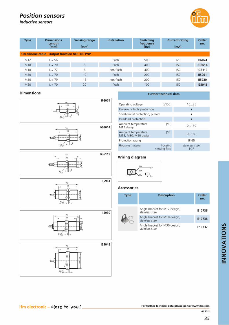
L = 56 3 120500 IF6074M12
M18
M18
M30
M30
M50
L = 70 5 150400 IG6614
L = 77 8 150400 IG6119
L = 70 10
Installation
flush
flush
non flush
flush 150200 II5961
L = 79 15 150200 II5930
L = 70 20 150100 I95045
non flush
flush
Inductive sensorsPosition sensors
Type Description Order no.
Accessories
Angle bracket for M30 design,stainless steel E10737
Angle bracket for M12 design,stainless steel E10735
Angle bracket for M18 design,stainless steel E10736
Type DimensionsLength[mm]
Operating voltage [V DC] 10...35
Reverse polarity protection •
Short-circuit protection, pulsed •
Overload protection •
Ambient temperature [°C]M12 design 0...150
Ambient temperature [°C]M18, M30, M50 design 0...180
Protection rating IP 65
Housing material housingsensing face
stainless steelLCP
Further technical data
BN
BK
BU
L+
L
Wiring diagram
Dimensions
48
M12
x1
56
417
IF6074
M18
x1
244
6070 IG6614
M18
x1
244
76077 IG6119
M30
x1,5
7060
536
II5961
M30
x1,5
536
97960
II5930
M50
x1,5
7060
555
I95045
36
Inductive and capacitive sensors for use in dust andgas areas
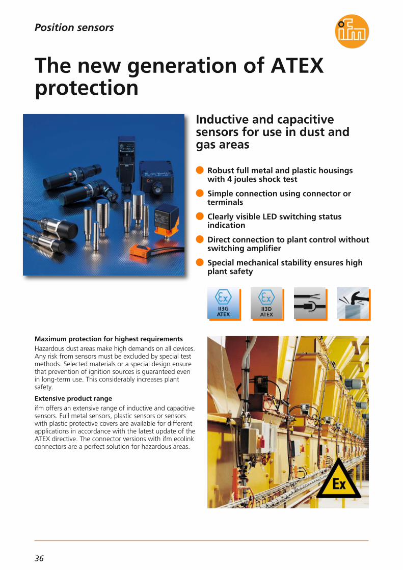
Maximum protection for highest requirementsHazardous dust areas make high demands on all devices.Any risk from sensors must be excluded by special testmethods. Selected materials or a special design ensurethat prevention of ignition sources is guaranteed evenin long-term use. This considerably increases plant safety.
Extensive product rangeifm offers an extensive range of inductive and capacitivesensors. Full metal sensors, plastic sensors or sensorswith plastic protective covers are available for differentapplications in accordance with the latest update of theATEX directive. The connector versions with ifm ecolinkconnectors are a perfect solution for hazardous areas.
Robust full metal and plastic housingswith 4 joules shock test
Simple connection using connector or terminals
Clearly visible LED switching status indication
Direct connection to plant control withoutswitching amplifier
Special mechanical stability ensures highplant safety
The new generation of ATEX protection
Position sensors

37
INN
OV
ATI
ON
S
Sensing range
[mm]
Operating voltage
[V]
CategoryOutput function Order no.
Inductive · M12 connector · full metal
3 f 10...36 DC 3D / 3GNO IF503A
Dimensions
[mm]
M12 x 60
M12 x 61 3 f 10...36 DC 3D / 3GNC IF504A
6 nf 10...36 DC 3D / 3GNO IF505AM12 x 70
M18 x 70 5 f 10...36 DC 3D / 3GNO IG510A
12 nf 10...36 DC 3D / 3GNO IG511AM18 x 71
M18 x 72 5 f 10...36 DC 3D / 3GNC IG512A
M30 x 70 10 f 10...36 DC 3D / 3GNO II502A
25 nf 10...36 DC 3D / 3GNO II503AM30 x 71
M30 x 72 10 f 10...36 DC 2D / 3GNO II504A
Inductive sensorscapacitive sensors
Position sensors
Inductive · M12 connector
40 nf 10...36 DC 3D / 3GNO and NC IM511A40 x 40 x 67
40 x 40 x 67 20 f 10...36 DC 3D / 3GNO and NC IM512A
30 nf 10...36 DC 3D / 3GNO and NC IM513A40 x 40 x 67
Type Description Order no.
Accessories
Angle bracket for type M30,stainless steel E10737
Lock nuts (2 pcs.),M12 x 1, high-grade st. steel (1.4571) E10025
Lock nuts (2 pcs.),M18 x 1, high-grade st. steel (1.4571) E10028
Lock nuts (2 pcs.),M30 x 1, high-grade st. steel (1.4571) E10031
Angle bracket for type M12,stainless steel E10735
Angle bracket for type M18,stainless steel E10736
Dimensions
4940
M12
x1
174
M12
x1
LED 4 x 90°
60 IF503A
40
M12
x1
174
10
M12
x1
7059
LED 4 x 90°
IF505A
5957
50
M18
x1
4
M12
x1
70
24LED 4 x 90°
IG510A
24
M18
x1
M12
x1
35 15
4
57
7059
LED 4 x 90°
IG511A
58
50
M30
x1,5
5
57
70
36
M12
x1
LED 4 x 90°
II502A
M30
x1,5
5
M12
x1
22,527,55759
70
LED 4 x 90° 36
II503A
40
67
40
54
30 2
45,5
5,5
29,5
M12
x130
45,534
LED5,5
IM511A

38
1) potentiometer
Sensing range
[mm]
Operating voltage
[V]
CategoryOutput function Order no.
Dimensions
[mm]
Inductive · 2 m cable · protective cover
8 nf 20...250 AC / DC 3DNO IG001AØ 23 x 102.3
Ø 23 x 102.3 8 nf 10...30 DC 3DNC IG513A
8 nf 10...30 DC 3Dprogrammable IG515AØ 23 x 102.3
Inductive · 6 m cable · protective cover
15 nf 20...250 AC / DC 3DNO II001AØ 34 x 104.1
Inductive · M12 connector · protectice cover
10 nf 10...30 DC 3DNO and NC IG514AØ 23 x 102.3
Inductive · terminal chamber
60 nf 20...250 AC / DC 3Dprogrammable ID002A105 x 80 x 42
105 x 80 x 42 60 nf 10...30 DC 3Dprogrammable ID502A
60 nf 10...30 DC 2Dprogrammable ID503A105 x 80 x 42
40 x 40 x 133 20 f 20...250 AC / DC 3Dprogrammable IM001A
40 nf 20...250 AC / DC 3Dprogrammable IM002A40 x 40 x 133
40 x 40 x 133 20 f 10...30 DC 3Dprogrammable IM506A
40 x 40 x 133 40 nf 10...30 DC 3Dprogrammable IM507A
20 f 10...55 DC 3Dprogrammable IM508A40 x 40 x 133
20 f 10...30 DC 3DNO and NC IM510A40 x 40 x 133
40 x 40 x 133 20 f 10...30 DC 3DNO IM509A
Dimensions
M18
x1
80186950
9
18,5
23
424
102,2
LED
IG001A
M18
x1
8068,552,7
18,5
23
424
84,5
LED
IG514A
5 29
104
9
M30
x1
LED
81186744
34,1
24
II001A
1
105
80
40
7,565
65
5,59,3
24
4212,6
2718
LED
16
ID002A
105133
40
54
30
45,5
29,5
40 7
45,585
34
LED
24
24
305,
5
IM001A
Position sensors

39
04.2013
INN
OV
ATI
ON
S
For further technical data please go to: www.ifm.com
Sensing range
[mm]
Operating voltage
[V]
CategoryOutput function Order no.
Dimensions
[mm]
Capacitive · terminal chamber
60 nf 20...250 AC / DC 3Dprogrammable KD001A105 x 80 x 42
105 x 80 x 42 60 nf 10...36 DC 3Dprogrammable KD501A
Capacitive · terminal chamber straight
15 nf 20...250 AC / DC 3Dprogrammable KI000AM30 x 150
M30 x 150 15 nf 10...30 DC 3DNO and NC KI503A
Capacitive · terminal chamber angled
15 nf 20...250 AC / DC 3Dprogrammable KI001AM30 x 125
M30 x 125 15 nf 10...30 DC 3DNO and NC KI505A
Type Description Order no.
2 m black, PUR cable EVC04A
5 m black, PUR cable EVC05A
10 m black, PUR cable EVC06A
25 m black, PUR cable EVC14A
Sockets M12, 4-pole
ecolink M12 – the secure connection in ATEX applications.This ecolink connectors series meets the strict require-ments of the standard and is therefore allowed for usein ATEX areas requiring categories 2D, 3D and 3G. It isa simple matter to tighten the connector so far that itcomplies with the ATEX requirements but cannot beloosened by hand.Please observe the recommended tightening torque of1.2...1.5 Nm or tighten by 3 clicks with a wrench!
Dimensions
M30
x1,5
24 36 5
6067
80128
1
150
17
28
236
KI000A
24
17
28
M30
x1,5
365
6067
801
2
24
125
36
KI001A
1
105
80
40
7,565
65
5,59,3
24
4212,6
2718
LED
16
KD001A
1) potentiometer2) tightening torque 10 Nm
Inductive sensorscapacitive sensors
Position sensors

40
Capacitive touch sensors incompact cylindrical design
Functions and technologyCapacitive touch sensors can be used, for example, asstart and stop function on machines, as enable switchand for opening and closing gates. Compared tomechanical switches the sensors operate without wear.Dynamic touch sensors detect an approaching humanhand and suppress interference such as water, layers of ice or foreign bodies to a large extent. However, agloved hand will still trigger them.Static touch sensors detect hands and objects eventhrough glass for as long as the sensing face is coveredwhich provides, for example, protection against vanda-lism. With the latching operating principle it is possibleto switch the sensor on by touching briefly and to switch it off again by touching briefly again. Furthermore, thehousing is resistant to oils and it is also impact andscratch resistant. It offers the protection rating IP 69K.LEDs for optical feedback signal that the sensor hasbeen activated. The green LEDs can be controlled sepa-rately and, for example, be used to indicate the statusof plant and machinery.
Dynamic, stable, latching functionprogrammable or preset
High IP 69K protection rating and widetemperature range -40...85 °C
Symbols on the sensing face can be selected separately
Easy installation into housing with Ø 22.5 mm bore thanks to M22 x 1.5 thread
Wear-free and maintenance-free thanks to switching without any mechanical pressure
Touch sensor – start, stop andacknowledge
Position sensors

41
11.2013
INN
OV
ATI
ON
S
Operating voltage [V DC] 24 (12...36)
Current consumption [mA] 30
Ambient temperature [°C] -40...85
Common technical data
Capacitive sensors
Dimensions
20,422
29,5
15,55,3
5
31
M22x1,5
Mounting optionsThe sensor can be installed in all housings with a Ø22.5 mm hole. The supplied lock nut is used for fixing.Thanks to the M22 thread the sensor can be used for screw mounting without lock nut. Installationalignment of the sensor is not necessary since the clipshowing the symbol for the sensing face is snappedin as the last step.Wiring is done via the tried-and-tested 3-wire technology.
Position sensors
Connection Current rating
[mA]
Protection Orderno.
Output function NO · DC PNP
dynamic 0.3 m PUR cable 500IP65, IP67, IP69K KT5101M22
Housing material
PA
dynamic 0.3 m PUR cable with M12 plug 500IP65, IP67, IP69K KT5102M22 PA
static 0.3 m PUR cable 500IP65, IP67, IP69K KT5105M22 PA
static 0.3 m PUR cable with M12 plug 500IP65, IP67, IP69K KT5106M22 PA
dynamic 0.3 m PUR cable 500IP65, IP67, IP69K KT5109M22 PA
Type Evaluation principle
Description Orderno.
Accessories
Socket, M12,2 m black, PUR cable EVC001
Socket, M12,5 m black, PUR cable EVC002
Socket, M12,2 m black, PUR cable EVC004
Socket, M12,5 m black, PUR cable EVC005
Symbol disc must be ordered separately
For further technical data please go to: www.ifm.com
Connection technology
Type Description Orderno.
Symbol disc, lettering: START E12377
Symbol disc, lettering: STOP E12378
Symbol disc,symbol: on E12379
Symbol disc,symbol: off E12380
Rotation lock for installation in control panels E12381
Mechanical protection for M22 touch sensors E12382

42
Only T-slot sensors with stable signal, independent ofthe welding duration time
Online configuration for ifm cylinder sensors:www.ifm.com/gb/cylinder-sensors
Intelligent cylinder sensorThe sensor detects the alternating field of the weld current and holds the output signal during this time, independently of the welding duration time. Then thesensor resumes normal switching operation (piston orno piston).
GMR cellThe GMR cell used works as a semiconductor elementaccording to the magnetoresistive principle and reactsto magnetic fields of the permanent magnet in thepneumatic cylinder.
Adapters for almost any cylinder profileThanks to the wide selection of optional adapters the T-slot sensor can be fixed to almost any clean-line, tierod, integrated profile or trapezoidal slot cylinder.
Flush in the T-slot, no protruding structures
With non-stick coating on the M8 or M12connectors
PTFE conduit on the cable
Convenient: Easy fit “drop from the top”into a slot
A short, 25 mm sensor for different cylinder profiles
Flush-mount cylinder sensors forweld-field detection
Position sensors

43
11.2013
INN
OV
ATI
ON
S
Cylinder sensorsPosition sensors
Type Description Orderno.
Accessories
For further technical details please visit: www.ifm.com
Connection technology
Type Description Orderno.
Socket, M8, 3-pole5 m, PUR cable EVW069
Socket, M8, 3-pole10 m, PUR cable EVW070
Socket, M12, 4-pole,2 m, PUR cable EVW001
Socket, M12, 4-pole,5 m, PUR cable EVW002
Type /Dimensions
[mm]
Electrical design
Protection rating/protection class
f
[Hz]
Iload
[mA]
Ambient temperature
[°C]
Orderno.
Connection cable 0.3 m with M12 connector rotatable · 3-wire · PUR
25 x 5 x 5.1 DC PNP IP 67, III> 3000 100-25...85 MK5214
Connection cable 0.3 m with M8 connector rotatable · 3-wire · PUR
25 x 5 x 5.1 DC PNP IP 67, III> 3000 100-25...85 MK5215
Operating voltage [V] 10...30 DC
Short-circuit protection, pulsed •
Protected against reverse polarity / overload protected • / •
LED display yellow
Repeatability [mm] < 0.2
Travel speed [m/s] < 10
Response sensitivity [mT] 2
Power-on delay time [ms] < 30
Housing material PA, stainless steel
Hysteresis [mm] typ. 1
Common technical data
Adapters,aluminium alloy, stainless steel E11988
Trapezoidal slot cylinder
Memorisation block,PA, stainless steel E11798
T-slot cylinder
Protective adapter against weld spatterCoated diecast zinc, stainless steel E12259
Ø clamping range 5...11 mm,aluminium / stainless steel E12231
Ø clamping range 9...13.5 mm,aluminium / stainless steel E12232
Ø clamping range 9...17 mm,aluminium / stainless steel E12233
Adapter for tie rod / integrated profile cylinders
Fixing strap, Ø piston 10...16 mm E11975
Fixing strap, Ø piston 20...25 mm E11976
Fixing strap, Ø piston 32 mm E11977
Fixing strap, Ø piston 40 mm E11978
Fixing strap, Ø piston 50 mm E11979
Fixing strap, Ø piston 63 mm E11980
Fixing strap, Ø piston 80 mm E11981
Fixing strap, Ø piston 100 mm E11982
Clean line cylinder

44
Extremely robust photoelectric sensors for industrial applications
Optimum choice for conveying applicationsThe OI design is designed for position detection in conveying where long ranges are needed. As diffusetype sensor the device is virtually independent of thecolour so that objects with different surfaces can be detected reliably without readjustment.The metallic housing with a solid M30 thread is extremely robust. Even without additional protectionthe sensor withstands impacts and shocks.
Simple switch point settingA special feature is the switch point setting using multiturn potentiometer and a distance scale. The revolutions and the scale value are linear to the distance(e. g. “1” = 100 mm, “2” = 200 mm etc.). So beforeconnecting the sensor the switch point can be set andseen from the sensor scale at any time. There is no easierway.
Resistant metal housing with M30 connection
Simple switch point setting viapotentiometer and distance scale.
Diffuse reflection sensor with backgroundsuppression or retro-reflective sensor
Long ranges up to 800 mm for diffuse reflection/15 m for retro-reflective systems
Ranges independent of colours
Photocell with easy setting fortough environments
Position sensors

45
04.2013
INN
OV
ATI
ON
S
For further technical data please go to: www.ifm.com
Infrared sensors / red light sensors
Diffuse reflection sensor with background suppression · M12 connector · 3-wire DC
Common technical data
Light spot diameter
[mm]
Light-on / dark-on mode
Current consumption
[mA]
Order no.
55* OIH580
Range
[m]
50...800 mm light-on 35
30* OIH280
100 x 130
600 mm
0.1...15 m**
light-on
dark-on
35
20 OIP280
Operating voltage [V DC] 10...30
Type of light red light 625 nm
Switching status indication LED yellow
Operation LED green
Protection rating, protection class IP 67, III
Short-circuit protection, pulsed •
Reverse polarity protection / overload protection • / •
Ambient temperature [°C] -25...60
Voltage drop [V] < 2.5
Current rating [mA] 200
Accessories
Type Description Order no.
Angle brackets,stainless steel (1.4301 / 304) E10737
Prismatic reflector, 50 x 50 mm, plastic E20744
Prismatic reflector, 80 x 80 mm, plastic E20739
Prismatic reflector, Ø 50 mm, plastic E20956
Prismatic reflector, Ø 80 mm, plastic E20005
Materials housing
lens
nickel-plated zinc alloy,
PMMA
Switching frequency
[Hz]
300
55* OIH58250...800 mm light-on 35 300
300
1000
Switching output
PNP
NPN
PNP
30* OIH282600 mm light-on 35 300 NPN
PNP
100 x 1300.1...15 m** light-on 20 OIP2811000 PNP
100 x 1300.1...15 m** dark-on 20 OIP2821000 NPN
100 x 1300.1...15 m** light-on 20 OIP2831000 NPN
Retro-reflective sensor with polarisation filter · M12 connector · 3-wire DC
* at maximum range** referred to prismatic reflector Ø 80 mm
Position sensors
Connection technology
Type Description Order no.
Socket, M12,2 m black, PUR cable EVC001
Socket, M12,5 m black, PUR cable EVC002
Socket, M12,2 m black, PUR cable EVC004
Socket, M12,5 m black, PUR cable EVC005
Dimensions
M30x1,5
M12x1
43 38
1811
75

46
Cost-optimised absoluteencoders – more functionsand bus interfaces
The multiturn encoder monitors the material feed ofsteel sheet rollers
More functions at a favourable priceThe new photoelectric absolute encoders with SSI interface detect position, angle, speed and distance inautomated plant and machinery. They complement the ifm product family and do notonly offer extended functionality and additional interfaces but also a convincing price/performance ratio. They arealso available in stainless steel versions.
Easy implementationThese single and multiturn encoders are available withsolid or hollow shaft. The additional interfaces and theremovable bus connection cap ensure easy wiring andprogramming. All common bus interfaces such as Profibus DPV1/2,ProfiNet and CANopen interface, EtherNet /IP, Device-Net or Modbus are provided.
Single and multiturn encoders
Easy wiring and programming
Solid and hollow shafts
Optional stainless steel version
Profibus DPV1/2, ProfiNet and CANopen interface EtherNet/IP, DeviceNet or Modbus
New absolute encoders
Sensors for motion control

47
11.2013
INN
OV
ATI
ON
S
Encoder
For further technical details please visit: www.ifm.com
Accessories
Type Description Order no.
Spring disc coupling, Ø 6 mm / 10 mm, die-cast zinc; PA E60117
Spring disc coupling, Ø 10 mm / 10 mm, die-cast zinc; PA E60118
Plastic beam coupling with stainless steel hub, Ø 10 mm / 10 mm E60193
Flexible coupling with clamp connection,Ø 6 mm / 10 mm, aluminium E60066
Flexible coupling with clamp connection,Ø 10 mm / 10 mm, aluminium E60067
Flexible coupling with adjusting screws,Ø 10 mm / 10 mm, aluminium E60022
Flexible coupling with adjusting screws,Ø 6 mm / 10 mm, aluminium E60028
Measuring wheel, Ø 159.15 mm / 10 mm, Hytrel TPE-E E60110
Measuring wheel, Ø 159.16 mm / 10 mm, aluminium, PU E60076
Measuring wheel, Ø 63.66 ± 0.1 mm / 10 mm, Hytrel TPE-E E60138
Measuring wheel, Ø 63.6 mm, 10 mm, aluminium E60095
Measuring wheel, Ø 63.66 ± 0.1 mm / 6 mm, aluminium E60137
Measuring wheel, Ø 63.6 mm / 6 mm, aluminium E60006
Sensors for motion control
Interface Housing material
Protection class
Order no.
Multiturn encoder · solid shaft
Profibus AluminiumIP 65, IP 66, IP 67 RM30066
Connection
Bus cap
Operating voltage[V DC]
10...30
Profibus AluminiumIP 65, IP 66, IP 67 RM300710 Bus cap10...30
ProfiNet AluminiumIP 65, IP 66, IP 67 RM301110 Bus cap10...30
CANopen AluminiumIP 65, IP 66, IP 67 RM70116 Bus cap10...30
CANopen AluminiumIP 65, IP 66, IP 67 RM701210 Bus cap10...30
Ø shaft
[mm]
Resolution
[Bit]
Singleturn encoder · solid shaft
Profibus AluminiumIP 65, IP 66, IP 67 RN300110 Bus cap10...30
CANopen AluminiumIP 65, IP 66, IP 67 RN70116 Bus cap10...30
CANopen AluminiumIP 65, IP 66, IP 67 RN701210 Bus cap10...30
Multiturn encoder · hollow shaft
Profibus AluminiumIP 64, IP 65, IP 66, IP 67 RM300812 Bus cap10...30
Connection technology
Type Description Order no.
Angle bracket,aluminium, black anodised E60035
Housing diameter [mm] 58
Ambient temperature [°C] -40...85
Maximum [1/min]mechanical rotational speed 12.000
Further technical data
EtherNet jumper, M12 plug / M12 plug 2 m, PVC cable
E21138
EtherNet, screened patch cable,2 m, PUR cable, M12 / RJ45 E12090
25
25
25
25
25
13
13
13
25
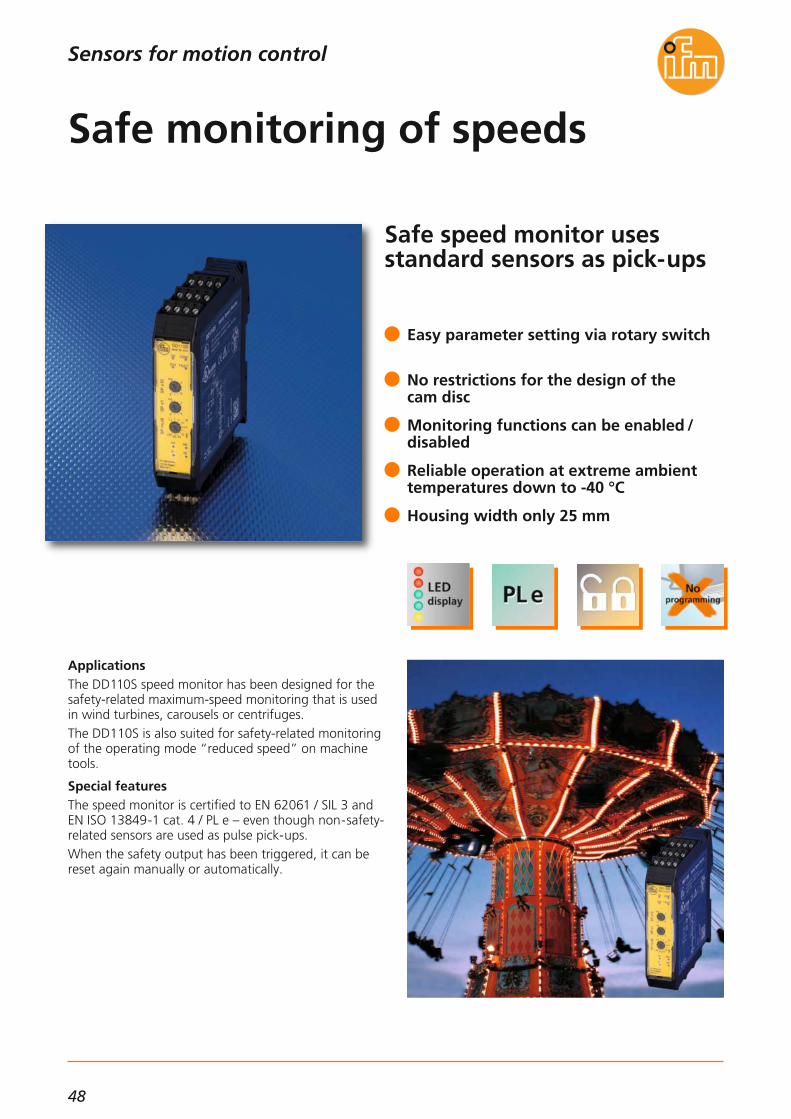
48
Safe speed monitor uses standard sensors as pick-ups
ApplicationsThe DD110S speed monitor has been designed for thesafety-related maximum-speed monitoring that is usedin wind turbines, carousels or centrifuges.The DD110S is also suited for safety-related monitoringof the operating mode “reduced speed” on machinetools.
Special featuresThe speed monitor is certified to EN 62061 / SIL 3 andEN ISO 13849-1 cat. 4 / PL e – even though non-safety-related sensors are used as pulse pick-ups.When the safety output has been triggered, it can bereset again manually or automatically.
Easy parameter setting via rotary switch
No restrictions for the design of the cam disc
Monitoring functions can be enabled /disabled
Reliable operation at extreme ambienttemperatures down to -40 °C
Housing width only 25 mm
Safe monitoring of speeds
Sensors for motion control

49
11.2013
INN
OV
ATI
ON
S
Safety speed monitor DD110S
Evaluation system for safe speed monitoring
Easy setting of the limit speedThe speed is determined via the interval measurementon the inputs where for example two inductive sensorsare used as pulse pick-ups.The user can set the limit speed easily and effectivelyvia three rotary switches (x 1, x 10, multiplier) – eitherin rpm or Hz. It was decided not to use any complicated setting menus.An easy and intuitive setting algorithm prevents unin-tentional change or manipulation of the set values.
More functionsAutomatic or manual reset of overspeed is possible.This function is set via wire links.The monitoring function can be enabled and disabledvia a switching input.Besides the 2-pole safety relay, transistor outputs canalso be used as output for the status and error indication.
For further technical details please visit: www.ifm.com
Dimensions
22,5
99 108
1
LED
2
114,5
3
35,5
Systems for pulse evaluationSensors for motion control
Operating voltage [V DC]19.2...28.8;
incl. 5 % residual ripple
Nominal voltage [V DC] 24
Current consumption [mA] ≤ 125
Sensor supply 24 V DC / ≤ 70 mA
Protection IP 20 / II
Input characteristicsPulse inputs S34, S43:
“1”: 6 mA / 24 V DC
Adjustable speed range [rpm] 10...49500
Adjustable frequency range [Hz] 0.1...990
Input frequency [Hz] ≤ 5000
Output function
2 safety-related switchingoutputs (floating contacts)
1 fault output “Fault”(positive switching)1 diagnostic output
“Overspeed” (positiveswitching)
Output characteristics
Fault output “Fault” Y7and diagnostic output
“Overspeed” Y8≤ 20 mA, 24 V DC,
voltage drop ≤ 2 V DC,short-circuit proof,
non safe
Contact rating
6 A, 250 V AC / 24 V DC
(≥ 6 mA); resistive load
Ambient temperature [°C] -40...55
Storage temperature [°C] -40...75
Max. permissible relative [%]humidity
95, non condensing
Housing materials PA (polyamide)
Mounting Rail TH35 (according to EN 60715)
ConnectionScrew terminals; 0.5...2.5 mm² (AWG 12...30)
1) Screw terminals2) Rotary switch3) DIN rail mounting
Wiring diagram
DD11xS
L- L+ S33 S34 S35 S44 S43 S45 13 23
(GND) (GND)
Y3 Y4 Y2 Y1 Y5 Y6 Y7 Y8 14 24
VCC = 24 V DC
24 V DC
Sensor 2 Sensor 1
K1 K2 K1
K2
Enable 1
Enable 2 Fault Overspeed
24 V Restart
Technical data

50
Frequency-to-current converterfor the conversion of pulse sequences into standard signal
The rotational speed of the master belt is transmitted asan analogue target value to the controller of the otherconveyor belts.
Converting frequencies into standard signalsThe programmable frequency-to-current converter re-ceives pulses from external pick-ups and calculates theirfrequency according to the interval measurement prin-ciple. Based on the set parameters, it generates an ana-logue standard signal (0/4...20 mA or 0...10 V) proportional to the calculated frequency / rotationalspeed.
Configurable switching outputsThe DW2503 has one transistor output and one relayoutput that switch on or off in case the set limit fre-quency is exceeded or not reached.
ConvenientThe high-contrast luminous OLED display and the menu-guided parameter setting are designed for maximumuser-friendliness.
Frequency-proportional current or voltage output
High input frequency of up to 60,000 pulses / minute
Configurable functions
Clearly readable, luminous OLED display
Extended operating temperature rangedown to -40 °C
Analogue frequency transmission
Sensors for motion control

51
04.2013
INN
OV
ATI
ON
S
For further technical data please go to: www.ifm.com
Further technical dataApplication exampleA typical application is the synchronisation of interac-ting conveyor belts. The rotational speed of the masterbelt is detected with a frequency-to-current converter.The speed of the second conveyor belt is re-adjusted bymeans of an analogue preset value from a frequencyconverter.
Analogue outputWith a withstand voltage of 500 V DC, the analogueoutput is electrically isolated from the supply voltage ofthe pulse pick-ups.The value of the output signal changes either inproportion or out of proportion to the input frequency.
Configurable output functionsWhen the limit frequency is exceeded or not reached,the relay and transistor outputs are switched on or off.They may also remain switched until they are manuallyreset. Optionally, the reset can take place automaticallyafter an adjustable period of time.The transistor outputs that can be used alternatively are switched to the relays synchronously. These can, forexample, be connected directly to a PLC in order totransmit status messages.
Dimensions
45 124,7
78 35,5
3
2
1
1 2 3 4 65
7 8 9 10 1211
13 14 15 16 1817
19 20 21 22 2423
Pulse evaluation systemsSensors for motion control
Function Nominal voltage
[V]
Pulse inputsAnalogue outputs Orderno.
Application: Conversion of pulse sequences into analogue standard signals
1 output with a switch point to monitor if the preset value is exceeded or not reached or to indicate
the acceptable range while providing the detected frequencyas analogue current or voltage signal.
110...240 AC (50...60 Hz) /
27 DC (typ. 24 DC)
PNP / NPN; NAMUR (24 V)
0/4...20 mA;0...10 V DW2503
Relay outputs
1 changeover contact; potential-free
6 A (250 V AC); B300, R300
Transistor outputs
1 x PNP; externally supplied
24 V DC / max. 15 mA;short-circuit protection
Setting range [Imp/min] 1...60000 (0.1...1000 Hz)
Ambient temperature [°C] -40...60
Storage temperature [°C] -40...85
Housing protection rating IP 50
Terminal protection rating IP 20
Function displayOLED display;
128 x 64 pixels luminous
Input signal indication LED yellow
Switching status indication LED green
1) OLED display2) Programming buttons3) LEDs

52
Speed monitor family withextended functions
Speed monitors switch when critical rotational speedsare exceeded or not reached.
Versatile speed monitoringThe speed monitors calculate the rotational speed byevaluating pulses. The transistor and relay outputsswitch when adjustable limit values are exceeded or notreached. This allows, for example, reliable overspeedand standstill detection.
VersionsThe speed monitors DD2503 and DD2603 monitor therotational speed of one channel with two separately adjustable limit values. A separate output is assigned toeach limit value.The speed monitors DD2505 and DD2605 monitor twoseparate input channels, each having one switch point.
ConvenientThe high-contrast luminous OLED display and the menu-guided parameter setting are designed for maximumuser-friendliness.
Monitoring of two limit values with separate output relays
High input frequency of up to 60,000 pulses / minute
Configurable functions, speed-proportionalanalogue output
Clearly readable, luminous OLED display
Extended operating temperature rangedown to -40 °C
Rotational speed monitoring andstandstill detection
Sensors for motion control

53
04.2013
INN
OV
ATI
ON
S
For further technical data please go to: www.ifm.com
Further technical dataDD2503, DD2505, DD2603, DD2605
Overspeed monitoring:Centrifuges, carousels or wind turbines are monitoredfor exceeded maximum rotational speed. The speedmonitor gives a switch-off signal as soon as the speedis too high. This makes sure that the resulting centrifugalforces will not destroy the system.
Standstill monitoringStandstill monitoring is used to detect torn conveyorbelts, to monitor the V-belts of ventilators or to detectblocked screw conveyors.The speed monitor signals a dysfunction in case of unexpected standstills of the non-driven side of the machine.
Versions including wire monitoringThe monitors DD2603 and DD2605 offer sensor cablemonitoring. In this case, NAMUR sensors must be applied.
Configurable output functionsThe relay outputs are switched on or off in case the limitvalues are exceeded or not reached. They may also re-main switched until they are manually reset. Optionally,the reset can take place automatically after an adjusta-ble period of time.The transistor outputs that can be used alternatively areswitched to the relays simultaneously. These can, for example, be connected directly to a PLC in order totransmit status messages.
Dimensions
45 124,7
78 35,5
3
2
1
1 2 3 4 65
7 8 9 10 1211
13 14 15 16 1817
19 20 21 22 2423
Pulse evaluation systemsSensors for motion control
Switching function Nominal voltage
[V]
Pulse inputs
Analogue outputs
Order no.
Application: Single pulse evaluation system with microprocessor for frequency; rotational speed; speed; pulses and machine cycles
1 input with 2 switch points to monitor if the preset value is exceeded or not reached
or to indicate the acceptable range
110...240 AC (50...60 Hz) / 27 DC
(typ. 24 DC)
PNP / NPN; NAMUR (24 V)0/4...20 mA DD2503
2 inputs having 1 switch point each to monitor if the preset value is exceeded or not reached
or to indicate the acceptable range
110...240 AC (50...60 Hz) / 27 DC
(typ. 24 DC)
PNP / NPN; NAMUR (24 V)– DD2505
1 input with 2 switch points to monitor if the preset value is exceeded or not reached
or to indicate the acceptable range
110...240 AC (50...60 Hz) / 27 DC
(typ. 24 DC)
NAMUR(EN 50227)0/4...20 mA DD2603
2 inputs having 1 switch point each to monitor if the preset value is exceeded or not reached
or to indicate the acceptable range
110...240 AC (50...60 Hz) / 27 DC
(typ. 24 DC)
NAMUR(EN 50227)– DD2605
Relay outputs2 changeover contacts
6 A (250 V AC); B300, R300
Transistor outputs
2 x PNP; externally supplied
24 V DC / max. 15 mA;short-circuit protection
Setting range [Imp/min] 1...60000 (0.1...1000 Hz)
Ambient temperature [°C] -40...60
Storage temperature [°C] -40...85
Housing protection rating IP 50
Terminal protection rating IP 20
Function displayOLED display;
128 x 64 pixels luminous
Input signal indication LED yellow
Switching status indication LED green
1) OLED display2) Programming buttons3) LEDs

54
Threshold relay for the detection and processing ofanalogue measuring values
Analogue sensor signals are evaluated. The outputswitches if limit values are exceeded or not reached.
Limit values of analogue signalsThe threshold relay DL2503 is a programmable analogueunit designed to evaluate physical variables that areavailable as analogue standard signals / sensor signals(0/4...20 mA). Extensive parameter setting options make it easy tomeet the requirements of the application.
Typical applications• Limit value monitoring of flow, pressure, temperature
or level.• Monitoring of the difference between inflow and
return flow• Pressure difference monitoring.
ConvenientThe high-contrast luminous OLED display and the menu-guided parameter setting are designed for maximumuser-friendliness.
Two analogue current inputs
Monitoring of two limit values with separate output relays
Configurable functions
Clearly readable, luminous OLED display
Extended operating temperature rangedown to -40 °C
The taming of physical variables
Sensors for motion control

55
04.2013
INN
OV
ATI
ON
S
For further technical data please go to: www.ifm.com
Further technical data
Dimensions
45 124,7
78 35,5
3
2
1
1 2 3 4 65
7 8 9 10 1211
13 14 15 16 1817
19 20 21 22 2423
Pulse evaluation systemsSensors for motion control
Switching function Nominal voltage
[V]
Analogue inputs
Analogue outputs
Orderno.
2-channel analogue threshold relay for analogue standard signals
2 switch points in mA or of the physical unit [°C; bar; etc.)6 switching functions (limit value exceeded
or not reached, window range) Subtraction and summation by means
of signal combination (In1-In2; In1+In2)
110...240 AC (50...60 Hz) / 27 DC
(typ. 24 DC)
2 x 0/4...20 mA
for sensors ortransmitters
1 x0/4...20 mA DL2503
Relay outputs 2 changeover contacts6 A (250 V AC);
B300, R300
Transistor outputs
2 x PNP; externally supplied
24 V DC / max. 15 mA;short-circuit protection
Setting range [Imp/min] 1...60000 (0.1...1000 Hz)
Ambient temperature [°C] -40...60
Storage temperature [°C] -40...85
Housing protection rating IP 50
Terminal protection rating IP 20
Function displayOLED display;
128 x 64 pixels luminous
Input signal indication LED yellow
Switching status indication LED green
1) OLED display2) Programming buttons3) LEDs
Operating principleThe analogue current signals at both inputs can be scaled, displayed and monitored separately. The startand end values of the current signal can be assignedany numerical value corresponding to the measuringrange of the sensor (e.g. 4 ... 20 mA = 10 ... 25 bar).The monitor compares the actual signal values with the set limit values and switches the assigned outputsaccording to the set parameter values and functions.The input signals can be scaled according to the mea-suring range of the sensor, so that the user may readthe physical units of the measured values directly on the display.The analogue output provides the input signal “IN 1”unchanged or scaled for further use.
Comparator modeIn the comparator mode, the monitor DL-2503 formsthe difference or the total from the two input signals(IN 1-IN 2, IN 1+IN 2). The differential or the total valuecan be displayed, evaluated, compared with the setlimit values and provided as an analogue signal. Theoutputs switch according to the set parameters andfunctions.

56
Direction monitor withintegrated rotational speedand standstill monitoring
In case of overload or brake failure, the direction monitordetects the unintentional lowering of the load.
Monitoring the direction of rotationThe direction monitors detect the direction of a shaftrotation by means of staggered pulses. Typically, two inductive sensors serve as pulse pick-ups. Dependingon which sensor is dampened first by the switchingcams, the direction of rotation can be determined.
VersionsThe DR2503 has a switching output indicating the direction of rotation and another switching output forspeed monitoring.The DR2505 has one switching output for clockwiseand another one for counter-clockwise rotation whileoffering simultaneous standstill detection.
ConvenientThe high-contrast luminous OLED display and the menu-guided parameter setting are designed for maximumuser-friendliness.
Rotational direction monitoring by meansof staggered pulse sequences
High input frequency of up to 60,000 pulses / minute
Configurable functions
Clearly readable, luminous OLED display
Extended operating temperature rangedown to -40 °C
Direction monitoring
Sensors for motion control

57
04.2013
INN
OV
ATI
ON
S
For further technical data please go to: www.ifm.com
Further technical dataDR2503, DR2505
Application example:Lifting systemsThe unit monitors if the load hook is lifted or loweredas expected. In case of overload or brake failure, the unintentional lowering of the load can be detected andavoided.PumpsThe unit monitors if the pump rotates in the correct direction.
Configurable output functionsIf clockwise / counter-clockwise rotation or under /overspeed are detected, the relay outputs will be switched on or off.All outputs may also remain switched until they are manually reset. Optionally, the reset can take place automatically after an adjustable period of time.The transistor outputs that can be used alternatively areswitched to the relays simultaneously. These can, for example, be connected directly to a PLC in order totransmit status messages. Dimensions
45 124,7
78 35,5
3
2
1
1 2 3 4 65
7 8 9 10 1211
13 14 15 16 1817
19 20 21 22 2423
Pulse evaluation systemsSensors for motion control
Pulse evaluation system with microprocessor for direction monitoring and frequency, rotational speed and speed
1 input with 1 switching output signalling the direction; 1 switching output to monitor if the limit value is exceeded
or not reached or to indicate the acceptable range
110...240 AC (50...60 Hz) / 27 DC
(typ. 24 DC)
PNP / NPN; NAMUR (24 V) DR2503
1 input with 2 switching outputs for separate direction signals;adjustable reset times for standstill monitoring
110...240 AC (50...60 Hz) / 27 DC
(typ. 24 DC)
PNP / NPN; NAMUR (24 V) DR2505
Relay outputs2 changeover contacts
6 A (250 V AC); B300, R300
Transistor outputs
2 x PNP; externally supplied
24 V DC / max. 15 mA;short-circuit protection
Setting range [Imp/min] 1...60000 (0.1...1000 Hz)
Ambient temperature [°C] -40...60
Storage temperature [°C] -40...85
Housing protection rating IP 50
Terminal protection rating IP 20
Function displayOLED display;
128 x 64 pixels luminous
Input signal indication LED yellow
Switching status indication LED green
1) OLED display2) Programming buttons3) LEDs
Pulse evaluation system with microprocessor for direction monitoring with separate indication of “right” and “left” rotation
Switching function Nominal voltage
[V]
Pulse inputs Orderno.

58
Slip monitor with integratedspeed monitoring
Slip monitors monitor the rotational speed of the deflection rollers and detect slipped drive belts.
Slip monitoringSlip is the rotational speed difference between the driven and the non-driven side of a power train. Rotational speed differences may occur as a result of a slipped coupling, V-belt or drive belt. The slip monitor calculates the rotational speed differencein per cent and switches off as soon as the limit value isreached. This avoids tear or damage caused by frictionheat.
Limit valuesTwo separate limit values can be monitored for slip androtational speed. The unit can be set to monitor if thelimit values are exceeded or not reached.
ConvenientThe high-contrast luminous OLED display and the menu-guided parameter setting are designed for maximumuser-friendliness.
One switch point for rotational speed andone for slip monitoring
High input frequency of up to 60,000 pulses / minute
Functions with parameter setting
Clearly readable, luminous OLED display
Extended operating temperature rangedown to -40 °C
Monitor relative speed to eliminate slip-ups
Sensors for motion control
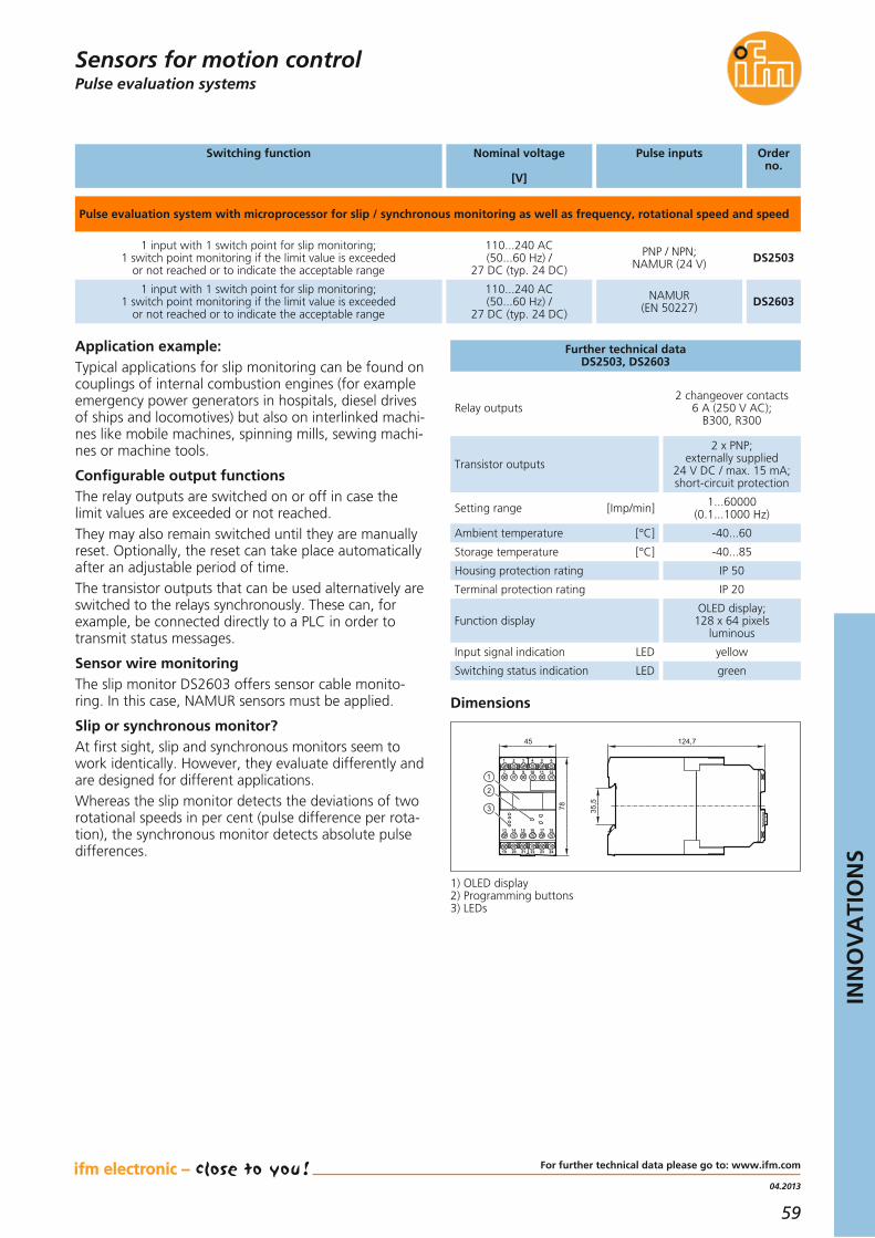
59
04.2013
INN
OV
ATI
ON
S
For further technical data please go to: www.ifm.com
Further technical dataDS2503, DS2603
Application example:Typical applications for slip monitoring can be found oncouplings of internal combustion engines (for exampleemergency power generators in hospitals, diesel drivesof ships and locomotives) but also on interlinked machi-nes like mobile machines, spinning mills, sewing machi-nes or machine tools.
Configurable output functionsThe relay outputs are switched on or off in case thelimit values are exceeded or not reached.They may also remain switched until they are manuallyreset. Optionally, the reset can take place automaticallyafter an adjustable period of time.The transistor outputs that can be used alternatively areswitched to the relays synchronously. These can, for example, be connected directly to a PLC in order totransmit status messages.
Sensor wire monitoringThe slip monitor DS2603 offers sensor cable monito-ring. In this case, NAMUR sensors must be applied.
Slip or synchronous monitor?At first sight, slip and synchronous monitors seem towork identically. However, they evaluate differently andare designed for different applications.Whereas the slip monitor detects the deviations of tworotational speeds in per cent (pulse difference per rota-tion), the synchronous monitor detects absolute pulsedifferences.
Dimensions
45 124,7
78 35,5
3
2
1
1 2 3 4 65
7 8 9 10 1211
13 14 15 16 1817
19 20 21 22 2423
Pulse evaluation systemsSensors for motion control
Pulse evaluation system with microprocessor for slip / synchronous monitoring as well as frequency, rotational speed and speed
1 input with 1 switch point for slip monitoring; 1 switch point monitoring if the limit value is exceeded
or not reached or to indicate the acceptable range
110...240 AC (50...60 Hz) /
27 DC (typ. 24 DC)
PNP / NPN; NAMUR (24 V) DS2503
1 input with 1 switch point for slip monitoring; 1 switch point monitoring if the limit value is exceeded
or not reached or to indicate the acceptable range
110...240 AC (50...60 Hz) /
27 DC (typ. 24 DC)
NAMUR(EN 50227) DS2603
Relay outputs2 changeover contacts
6 A (250 V AC); B300, R300
Transistor outputs
2 x PNP; externally supplied
24 V DC / max. 15 mA;short-circuit protection
Setting range [Imp/min] 1...60000 (0.1...1000 Hz)
Ambient temperature [°C] -40...60
Storage temperature [°C] -40...85
Housing protection rating IP 50
Terminal protection rating IP 20
Function displayOLED display;
128 x 64 pixels luminous
Input signal indication LED yellow
Switching status indication LED green
1) OLED display2) Programming buttons3) LEDs
Switching function Nominal voltage
[V]
Pulse inputs Orderno.

60
Synchronous monitor for slipand synchronous monitoring
Synchronous monitors are used when several powertrains are to be synchronised.
Synchronous monitoringThe synchronous monitor compares the pulse sequencesgenerated on two moving machine parts. As soon asthese two parts move at different speeds or at differentangles of deflection, the synchronous monitor switches.
Operating principleThe synchronous and slip evaluation is done by means ofpulse differences. Both the reset time and the numberof pulse differences that are just about acceptable canbe set by the user.
ConvenientThe high-contrast luminous OLED display and the menu-guided parameter setting are designed for maximumuser-friendliness.
Monitoring of two limit values with separate output relays
High input frequency of up to 60,000 pulses / minute
Configurable functions
Clearly readable, luminous OLED display
Extended operating temperature rangedown to -40 °C
Monitor absolute speed difference to keep it straight
Sensors for motion control

61
04.2013
INN
OV
ATI
ON
S
For further technical data please go to: www.ifm.com
Further technical dataDS2505, DS2506, DS2605
Application example:
Lifting platformBoth pairs of scissors of the lifting platform must besynchronised to make sure that the platform will be lifted horizontally. Each of them is moved by a spindledrive. The synchronous monitor detects the number ofrevolutions of both spindles.
Gantry craneThe platform of the gantry crane has to be moved withgreat precision to avoid wedging.On each side of the platform, the distance is measuredby means of inductive sensors detecting the teeth of arack.
Configurable output functionsThe relay outputs are switched on or off in case thelimit values are exceeded or not reached.They may also remain switched until they are manuallyreset. Optionally, the reset can take place automaticallyafter an adjustable period of time.The transistor outputs that can be used alternatively are switched to the relays synchronously. These can, forexample, be connected directly to a PLC in order totransmit status messages.
Sensor wire monitoringThe synchronous monitor DS2605 offers sensor cablemonitoring. In this case, NAMUR sensors must be applied.
Slip or synchronous monitor?At first sight, slip and synchronous monitors seem towork identically. However, they evaluate differently andare designed for different applications.Whereas the slip monitor detects the deviations of tworotational speeds in per cent (pulse difference per rota-tion), the synchronous monitor detects absolute pulsedifferences.
Dimensions
45 124,7
78 35,5
3
2
1
1 2 3 4 65
7 8 9 10 1211
13 14 15 16 1817
19 20 21 22 2423
Pulse evaluation systemsSensors for motion control
Switching function Nominal voltage
[V]
Pulse inputs Orderno.
Pulse evaluation system with microprocessor for slip and synchronous monitoring, evaluation of pulse differences
1 input with 2 switch points for slip and synchronous monitoring by means of pulse differences
110...240 AC (50...60 Hz) / 27 DC
(typ. 24 DC)
PNP / NPN; NAMUR (24 V) DS2505
1 input with 2 switch points for synchronous monitoring by means of pulse differences
110...240 AC (50...60 Hz) / 27 DC
(typ. 24 DC)
PNP / NPN; NAMUR (24 V) DS2506
1 input with 2 switch points for slip and synchronous monitoring by means of pulse differences
110...240 AC (50...60 Hz) / 27 DC
(typ. 24 DC)
NAMUR(EN 50227) DS2605
Relay outputs2 changeover contacts
6 A (250 V AC); B300, R300
Transistor outputs
2 x PNP; externally supplied
24 V DC / max. 15 mA;short-circuit protection
Setting range [Imp/min] 1...60000 (0.1...1000 Hz)
Ambient temperature [°C] -40...60
Storage temperature [°C] -40...85
Housing protection rating IP 50
Terminal protection rating IP 20
Function displayOLED display;
128 x 64 pixels luminous
Input signal indication LED yellow
Switching status indication LED green
1) OLED display2) Programming buttons3) LEDs

62
Visual assessment of distance, level or volume
Object detection in three dimensions –efector PMD 3defector pmd 3d is the first industrial 3D sensor that candetect objects in three dimensions at a glance. The newwide-angle version provides a wider angle of apertureof 64° x 48°.The time-of-flight measurement in three dimensionsenables the assessment of different applications, for example the detection of volume, distance or level.Special feature: The time-of-flight measurement andevaluation are integrated on one chip. The sensor chiphas 64 x 48 pixels. Each pixel of this chip matrix evaluates its distance to the object. This results in 3,072 distancevalues at the same time. The image of the object on the chip matrix and the respective distance values correspond to a 3D image.These values enable the detailed assessment of the object’s or scene’s characteristics up to a range of 5.5 m with an unambiguous range up to 48 m.
Wide-angle version with an angle of aperture of 64° x 48°
Operating principle: Time-of-flight measurement based on pmd technology
Illumination, time-of-flight measurementand evaluation in one housing
3,072 distance values per measurement for the detailed assessment of the application
4...20 mA / 0...10 V analogue output or 2switching outputs for providing the result
Even more at a glance: 3D vision sensor
Industrial imaging

63
11.2013
INN
OV
ATI
ON
S
3D sensors / 3d cameras
Accessories
Type Description Orderno.
For further technical details please visit: www.ifm.com
Industrial imaging
Connection technology
Socket, M12,2 m, PUR cable, 8 poles E11950
Socket, M12,5 m, PUR cable, 8 poles E11807
Socket, M12,10 m, PUR cable, 8 poles E11311
Operating software for 3D sensor E3D200
Mounting set for clamp mounting,Ø 14mm / stainless steel E3D103
Rod, 100 mm, Ø 14mm,M12 thread, stainless steel E20939
Technical dataO3D222, O3D223
Function display LED 4 x yellow, 4 x green
Result display / dialogue 4-digit 10-segment display
Operating voltage [V] 24 DC (± 10 %)
Current consumption [mA] < 1000 (max. 2500)
Current rating [mA] 100(per switching output)
HousingMaterial Front lens
Display window
Diecast aluminiumPMMA
PC
Trigger
Switching inputs
External: 24V PNP acc. toIEC 61131-2 type 2,
internal
Max: 2 (configurable),24 V PNP to.
IEC 61131-2 type 2
Switching outputsMax: 2
(configurable)24 V PNP
Analogue outputconfigurable
scalable
4...20 mA toIEC 61131-2,
Max. load current 300 Ω0...10 V to
IEC 61131-2,Min. load 10 kΩ
Short-circuit protection, pulsed •
Overload protection •
Ambient temperature [°C] -10...50
Storage temperature [°C] -40...85
Protection rating, protection class IP 67, III
Parameter setting interface Ethernet 10Base-T /100 Base-TX
DN3011Switched-mode power supply 24 V DC,primary, output current 2.5 A, regulated
DN1031Switched-mode power supply 24 V DC,primary, output current 2.5 A, regulated
Parameter setting options
Via PC / notebook or
10-segment display and 2 pushbuttons
Rod, 200 mm, Ø 14mm,stainless steel E21228
Rod, 300 mm, Ø 14mm,stainless steel E21229
Rod, 500 mm, Ø 14mm,stainless steel E21232
Ethernet, cross-over patch cable,2 m, PUR cable, M12 / RJ45 E11898
Ethernet, cross-over patch cable,10 m, PUR cable, M12 / RJ45 E12204
Ethernet, cross-over patch cable,20 m, PUR cable, M12 / RJ45 E12205
Type Description Orderno.
Type Type of sensor
Resolution pixels
[pixesl]
IlluminationAngle of aperturehorizontal x vertical
[°]
Orderno.
PMD 3D sensor · Type O3D · M12 connector
PMD 3D chip 64 x 48 Infrared LED (850 nm)64 x 48 O3D222
PMD 3D camera · Type O3D · M12 connector
PMD 3D chip 64 x 48 Infrared LED (850 nm)64 x 48 O3D223
Max. sampling rate
[Hz]
20(adjustable)
20(adjustable)

64
External LED illumination for sophisticated object recognition
Sophisticated object recognitionThe high-quality LED illumination creates homogeneouslight – either for virtually shadow-free object illumination or for emphasising surface characteristics such as dot-peened codes, scratches or nicks.They are available as M12 connector versions with visiblewhite, red or invisible infrared light.
Practical accessories A diffuser attachment made of high-quality glass forthe ring lights additionally ensures homogeneous illumination without disturbing reflections in applications with reflective surfaces in the close range.The optional angle bracket and the tried-and-tested ifm mounting system facilitate the alignment of the different types of additional illumination.
Homogeneous and virtually shadow-freeillumination of the object
Permanent light or pulse operation with the option of additional high light intensity
White light, red light and infrared versions
Compact design and robust, industriallycompatible housing
Combination with a diffuser attachmentpossible for “cloudy day” illumination
Vision sensors in the right light
Industrial imaging

65
11.2013
INN
OV
ATI
ON
S
For further technical data please go to: www.ifm.com
Illumination units
Accessories
Type Description Order no.
Mounting kit for ring light E2D201
Diffuser for ring light E2D202
Industrial imaging
Wiring diagram
L+
L
1
4
2
3
Pigtail: 4 trigger2 high light intensity
No high light intensity for O2D920
Common technical data
Operating voltage [V] 24 DC
Light source LED
Ambient temperature [°C] -10...55
Materialhousing
Trigger [V]
aluminiumanodised
Materialoptical area glass
5...24, PNP
Protected against reverse polarity •
Short-circuit proof •
Fixing M4 screws
Eye safety IEC 62471
Dimensions
[mm]
Active lighting source size
[Ø mm]
Current consumption
[mA]
ProtectionAngle of aperture
Order no.
Ring light, red light 617 nm
Ø 122 × 20.5 Ø 106 / Ø 66 800 / 1300* IP 6560° O2D915
Ring light, infrared light 875 nm
Ø 122 × 20.5 Ø 106 / Ø 66 800 / 1400* IP 6550° O2D917
Pigtail,0.3 m
•
•
Automatic deactivation at a housing temperature of 65 °C.* current consumption at high light intensity
Ring light, white light 5600 K
Ø 122 × 20.5 Ø 106 / Ø 66 800 / 1200* IP 65120° O2D919•
Connection technology
Type Description Order no.
Socket, M12,2 m black, PUR cable EVC001
Socket, M12,5 m black, PUR cable EVC002
Mounting kit for bar illumination unit E2D114
Mounting kit for 4 bar illumination units10 x 75 mm E2D116
Mounting kit for dark field illumination E2D115
Bar illumination unit red light 617 nm
116 x 18 x 13 10 x 75 225 / 375* IP 6560° O2D921
Bar illumination unit infrared light 875 nm
116 x 18 x 13 10 x 75 185 / 325* IP 6550° O2D922
•
•
Bar illumination unit white light 5600 K
116 x 18 x 13 10 x 75 165 / 275* IP 65120° O2D923•
200 x 18 x 13 10 x 150 460 / 700* IP 6560° O2D924
200 x 18 x 13 10 x 150 415 / 640* IP 6550° O2D925
•
•
200 x 18 x 13 10 x 150 265 / 475* IP 65120° O2D926•
Dark field illumination red light 617 nm
155 x 130 x 10 Ø 90 400 IP 54– O2D920•

66
Optimised PT pressuretransmitter with analoguecurrent output
Monitoring of hydraulics on a press
Optimised price / performance ratioThe new generation of PT pressure sensors now has an integrated thin film cell instead of a strain gaugemeasuring cell. Thanks to this, PT540x series pressuresensors offer greater accuracy at the best possible price / performance ratio, complementing the range ofifm’s pressure sensors.
The applicationsThe PT type sensors are optimised for industrial appli-cations with oils, compressed air or water. Since themeasuring cell is welded directly to the housing, no separate seal is required. The measuring cell is resistantto pressure peaks.High vibration and shock resistance as well as protec-tion rating IP 67 and IP 69K perfectly comply with therequirements of this field of application.
Slim, compact design with G 1/4 processconnection
Measuring accuracy ≤ ± 0.5 %, repeatability < ± 0.05 %.
Easy connection via M12 connector
Optimised price / performance ratio
Completely made of stainless steel
Small, compact and cost-savingpressure transmitter
Process sensors

67
04.2013
INN
OV
ATI
ON
S
For further technical data please go to: www.ifm.com
Pressure sensors
Accessories
Type Description Order no.
Operating voltage [V DC] 8.5...36
Common technical data
Medium temperature [°C] -40...90
Wetted partsNBR,
high-grade stainless steel (1.4542)
Protection IP 67 / IP 69K
Step response time [ms] 1
Reverse polarity protection •
Adapter; G 1/4 - G 1/2, stainless steel (1.4571 / 320S31) E30135
Process sensors
Relative pressuremeasuring range
[bar]
Poverloadmax. [bar]
Pburstmin. [bar]
Order no.
Output function 4…20 mA
PT5404
PT5403
PT5402
PT5401
PT5400
Accuracy / deviations (in % of the span)Deviation of the characteristicsLinearityHysteresis
Temperature coefficients in thetemperature range -25...90°C (in % of the span per 10 K)Temperature coefficient of zeroTemperature coefficient of the span
< ± 0.5< ± 0.1 BFSL / < ± 0.2 LS
< ± 0.2
< ± 0.1< ± 0.1
Connection technology
Type Description Order no.
Socket, M12,2 m black, PUR cable EVC001
Socket, M12,5 m black, PUR cable EVC002
Socket, M12,2 m black, PUR cable EVC004
Socket, M12,5 m black, PUR cable EVC005
L+
L
1
2
Wiring diagram
0...10 25 300
0...25 60 600
0...100 200 1000
0...250 500 1200
0...400 800 1700

68
Process sensors
For efficient compressed aircontrol and filter monitoring
Pressure monitoring in pneumatic systems
Filter monitoring, pneumatics and energy efficiencyRelative or differential pressure – the improved PQ seriespressure sensors measure both. Ideal for condition-based maintenance, for example when a filter is exchanged or leakage is detected by pressure loss.
Moisture-proof and preciseThe coated silicon measuring cell guarantees high over-load resistance and an accuracy of ± 0.5 %. The specialcoating protects the measuring cell from air humidityand condensate.
Parameter settingThe parameter setting can be carried out via two push-buttons or IO-Link interface.The compact sensors offer an analogue and a switchingoutput, both of which are configurable.
One analogue output and one programmable switching output
For differential or relative pressure measuring
Two-colour LED display for immediate status detection
Moisture-proof silicon measuring cell
Measuring range -1...1 bar and -1...10 bar.
Compact analogue pressure sensor
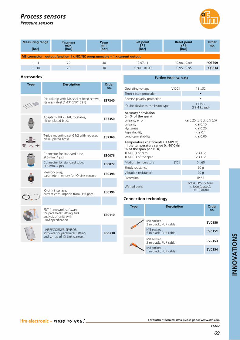
69
04.2013
INN
OV
ATI
ON
S
For further technical data please go to: www.ifm.com
Process sensorsPressure sensors
Operating voltage [V DC] 18...32
Further technical data
Connection technology
Type Description Order no.
M8 socket,2 m black, PUR cable EVC150
M8 socket,5 m black, PUR cable EVC151
M8 socket,2 m black, PUR cable EVC153
M8 socket,5 m black, PUR cable EVC154
M8 connector · output function 1 x NO/NC programmable + 1 x current output
-1...1 20 PQ380930 -0.97...1 -0.98...0.99
Measuring range
[bar]
Order no.
Poverloadmax. [bar]
Pburstmin. [bar]
-1...10 20 PQ383430 -0.90...10.00 -0.95...9.95
Set pointSP1[bar]
Reset point rP1
[bar]
Short-circuit protection •
Reverse polarity protection •
IO-Link device transmission type COM2 (38.4 kbaud)
Medium temperature [°C] 0...60
Protection IP 65
Shock resistance 50 g
Vibration resistance 20 g
Wetted partsbrass, FPM (Viton),
silicon (plated),PBT (Pocan)
Accuracy / deviation(in % of the span)Linearity errorLinearityHysteresisRepeatabilityLong-term stability
Temperature coefficients (TEMPCO)in the temperature range 0...60°C (in% of the span per 10 K)TEMPCO of zeroTEMPCO of the span
<± 0.25 (BFSL), 0.5 (LS)< ± 0.15< ± 0.25< ± 0.1< ± 0.05
< ± 0.2< ± 0.2
Accessories
Type Description Order no.
DIN rail clip with M4 socket head screws,stainless steel (1.4310/301S21) E37340
Adapter R1/8 - R1/8, rotatable,nickel-plated brass E37350
T-pipe mounting set G1/2 with reducer,nickel-plated brass E37360
Connector for standard tube, Ø 6 mm, 4 pcs. E30076
Connector for standard tube, Ø 8 mm, 4 pcs. E30077
Memory plug, parameter memory for IO-Link sensors E30398
IO-Link interface, current consumption from USB port E30396
FDT framework software for parameter setting and analysis of units with DTM specification
E30110
LINERECORDER SENSOR, software for parameter setting and set-up of IO-Link sensors
ZGS210

70
Process sensors
Hygienic pressure sensor with diaphragm seal for hightemperature applications
ApplicationThe PI22/PI23 series pressure sensors are designed for high-temperature applications as can among others be found in UHT plants (ultra high temperature).
Flexible: 2, 3 or 4 wires The pressure sensors with clearly visible LED display cannot only be connected as 3- or 4-wire units but also asloop-powered 2-wire units. This reduces the wiringcomplexity in new installations and facilitates exchangein existing 2-wire connections.
Parameter settingThe parameters can either be set via the buttons on thesensor or via IO-Link interface: via USB IO-Link master,PLC or memory plug.
Pressure monitoring in the temperaturerange from -25 to 200 °C
Integrated 1.5" or 2" clamp diaphragm seal with stainless steel membrane
All wetted parts made of stainless steel
Programmable analogue output in 2-wireoperation and display
6-point factory calibration certificate supplied
Hygienic pressure sensor for high temperatures

71
11.2013
INN
OV
ATI
ON
S
For further technical data please go to: www.ifm.com
Process sensorsPressure sensors
Accessories
Type Description Order no.
Memory plug, parameter memory for IO-Link sensors E30398
IO-Link interface, current consumption from USB port E30396
LINERECORDER SENSOR, software for parameter setting and set-up of IO-Link sensors
ZGS210
Clamp 1.5" · output function switching output PNP/NPN programmable + analogue output programmable
-1...25 PI2203
-1...10 PI2204
-1...4
80
50
30
-1.00...18.74
-1.0...7.5
-1.00...3.00
5.24...25.00
1.5...10.00
0.00...4.00 PI2205
Relative pressuremeasuring range
[bar]
Order no.
Poverloadmax. [bar]
Analogue start point
[bar]
Analogue end point
[bar]
-0.96...25.00
-0.98...10.00
-0.990...4.000
-0.124...2.5 PI2206
-0.05...1 PI2207
-1...1
20
10
10
-0.124...1.880
-0.05...0.75
-1...0.5
0.500...2.500
0.2...1.00
-0.5...1 PI2209
-0.120...2.500
-0.048...1.00
-0.998...1
Set pointSP1[bar]
-1.00...24.96
-1.00...9.98
-1.000...3.990
-0.124...2.496
-0.05...0.998
-1...0.998
Reset pointrP1
[bar]
0.02
0.01
0.005
0.002
0.001
0.001
Step incre-ment[bar]
Operating voltage [V DC] 20...32 (2-wire), 18...32 (3-wire)
Current rating [mA] 250 (3-wire)
Current consumption [mA] 3.6...21 (2-wire),< 45 (3-wire)
IO-Link Device type of transmission COM2 (38.4 kbaud), IO-Link 1.0
Accuracy / deviation(in % of the span) turn down 1:1Deviation of the switch pointLinearity errorLinearityHysteresisRepeatabilityLong-term stabilityTemperature coefficients (TEMPCO)in the temperature range 0...70°C (in % of the span per 10 K)Greatest TEMPCO of zeroGreatest TEMPCO of the span
< ± 0.2< ± 0.2< ± 0.15< ± 0.15< ± 0.1< ± 0.1
< ± 0.05< ± 0.15
Wetted parts stainless steel (1.4435 / 316L)
Medium temperature [°C] -25...200
Ambient temperature [°C] -25…80 (< 160 °C),-25…60 (< 200 °C)
Protection IP 68 / IP 69K
Further technical data
1) connection for 2-wire operation2) connection for 3-wire operation3) connection for IO-Link
parameter setting (P = communication via IO-Link)
4
1
3
2L+
L
OUT2
OUT1
2
4
1
3
2L+
L
P
3
L+
L
1
2
1
Wiring diagram
Connection technology
Type Description Order no.
Socket, M12, 4-pole,5 m orange, PVC cable EVT004
Socket, M12, 4-pole,2 m orange, PVC cable EVT067
USB IO-Link master for parameter setting and analysis of units
E30390
Clamp 2" · output function switching output PNP/NPN programmable + analogue output programmable
-1...25 PI2303
-1...10 PI2304
-1...4
80
50
30
-1.00...18.74
-1.0...7.5
-1.00...3.00
5.24...25.00
1.5...10.00
0.00...4.00 PI2305
-0.96...25.00
-0.98...10.00
-0.990...4.000
-0.124...2.5 PI2306
-0.05...1 PI2307
-1...1
20
10
10
-0.124...1.880
-0.05...0.75
-1...0.5
0.500...2.500
0.2...1.00
-0.5...1 PI2309
-0.120...2.500
-0.048...1.00
-0.998...1
-1.00...24.96
-1.00...9.98
-1.000...3.990
-0.124...2.496
-0.05...0.998
-1...0.998
0.02
0.01
0.005
0.002
0.001
0.001

72
Two switching outputs programmable
Flow sensor in a cooling water monitoring application.
Simple, fast and flexible installationThanks to a broad selection of process adapters, theSI0521 flow sensor can easily be integrated in almostany application. The robust stainless steel housing provides high reliability even in cases of harsh environmental conditions.The unit is unaffected by the orientation of the sensingface with respect to the direction of flow, providing increased flexibility of installation.Easy handling and high functionalityA pushbutton is used to set the flow range and adjustthe switch. Current flow and switch point are indicatedlocally by multi-coloured LEDs.Electronic locking of the settings and factory reset ofthe parameters provide additional safety.
High repeatability across the extendedmeasuring range.
Simple setting mode for quick set-up.
Variable process connection using adapters.
Reliable monitoring of liquids.
Electronic locking of the setting values.
Flow sensor with GermanischerLloyd approval
Process sensors

73
11.2013
INN
OV
ATI
ON
S
Flow sensors / flow meters
For further technical details please visit: www.ifm.com
Connection technology
Type Description Orderno.
Socket, M12,2 m black, PUR cable EVC004
Socket, M12,5 m black, PUR cable EVC005
Socket, M12,2 m black, PUR cable EVC001
Socket, M12,5 m black, PUR cable EVC002
Process sensors
Setting rangeliquids[cm/s]
Largestsensitivity
[cm/s]
Medium temperature
[°C]
Response time
[s]
Ub
[V]
IB
[mA]
Orderno.
M12 connector · 2 x normally open / normally closed programmable
3...300 3...100 -15...70 1...10 18...32 DC 2 x 250 SI0521
Further technical data
Nominal pressure [bar] 75
Short-circuit protection, pulsed •
Reverse polarity protection / overload protection • / •
Sensor material / housing
High-grade stainless steel(316L/1.4404) /stainless steel (1.4301/304)
Switch point setting Viapushbutton
Ambient temperature [°C] -25...80
Optical function indication LED 10
Protection rating / protection class IP 67, III
Power-on delay time [s] 10
Repeatability(% of the measured value) 1...5 (5...100 cm/s)
TypeSI0521
22
1 2
113
60 65
14
8,2
45
50
27
63
M12
x1
3
Dimensions
Accessories
Type Description Orderno.
Adapter M18 x 1.5 - L18 for mounting inT pieces E40104
Adapter, M18 x 1.5 - G 1/2 E40096
Adapter, M18 x 1.5 - G 1/4 E40099
Welding adapter,M18 x 1.5 - Ø 24 mm E40124
L
L+
3
2
4
1
S2 S1
Wiring diagram
1) LED bar display2) Set button3) Tightening torque 25 Nm

74
Screw-in, bolt-on and cylindrical Pt100 temperaturesensors
Pt100 temperature sensor attached to an oil tank tomonitor the housing temperature.
Suits many different requirementsEvery application has its own requirements as regardsthe temperature sensors to be used. Criteria such asbasic and housing material or design are as importantas the connection to control monitors. The new ifm electronic screw-in and bolt-on sensorsare designed to cover a large range of applications invarious industries (machine tools, etc.).
Cylindrical design Ø 6 mm or Ø 10 mm
M5 and M6 screw-in sensors, bolt-on sensors for M6 screws
Simple and 100 % sealed connection via ecolink M12 connector
PUR cable for lower cost
Different cable lengths from 2 to 5 m
Great value for money – the TS series temperature sensors
Process sensors

75
11.2013
INN
OV
ATI
ON
S
For further technical data please go to: www.ifm.com
Temperature sensors
Type Order no.
Measuringrange[°C]
Housing material
Response dynamicsT05 / T09
[s]
Measuring element Pt100
TS2229Bolt-on sensor12 x 35 for M6 -25...90 stainless steel
(1.4303 / 304) 9 / 15
Screw-in sensorM5 -30...90 high-grade stainless steel
(1.4404 / 316L)
Connection
PUR cable, 2 mM12 connector
PUR cable, 2 mM12 connector 3 / 8
Dimensions
1) tightening torque 1.5 Nm
TS2789
CylindricalØ 10 mm, l 50 mm -40...90 high-grade stainless steel
(1.4404 / 316L)PUR cable, 2 mM12 connector 6 / 25 TS2089
CylindricalØ 6 mm, l 45 mm -40...90 high-grade stainless steel
(1.4404 / 316L)PUR cable, 2 mM12 connector 3 / 10 TS2289
CylindricalØ 10 mm, l 50 mm -40...90 high-grade stainless steel
(1.4404 / 316L)PUR cable, 5 mM12 connector 6 / 25 TS5089
CylindricalØ 6 mm, l 45 mm -40...90 high-grade stainless steel
(1.4404 / 316L)PUR cable, 5 mM12 connector 3 / 10 TS5289
CylindricalØ 6 mm, l 45 mm -40...90 high-grade stainless steel
(1.4404 / 316L)PUR cable, 2.5 mM12 connector 3 / 10 TS9289
Process sensors
Evaluation electronics
Description Order no.
Control monitor,1 x analogue output, 1 x PNP/NPN TR2432
Control monitor2 x PNP/NPN TR7432
Measured signal converter,Pt100 / Pt1000 in 4...20 mA, scaling 0...100 °C TP3237
Measured signal converter,Pt100 / Pt1000 in 4...20 mA, scaling 50...150 °C TP3231
Measured signal converter,Pt100 / Pt1000 in 4...20 mA, scaling 50...300 °C TP3232
Measured signal converter,Pt100 / Pt1000 in 4...20 mA, scaling 0...300 °F TP3233
Measured signal converter,Pt100 / Pt1000 in 0...10 mA, scaling 0...100 °C TP9237
M12
x1
49,5
14 35
6,5
51
12
17
8,7
1,8
25,7
5,4
M54
8
8
M12
x1
49,5
14
M12
x1
7248
50
12
10742
TS2229
TS2789
TS2089, TS5089
M12
x1
64572
48
TS2289, TS5289, TS9289
Dimensions
34
6,5
47
12,5
17
8,7
2,7
TS2239
13
M12
x1
49,526
8
4 M6
TS2689
TS2239Bolt-on sensor12.,5 x 34 for M6 -25...90 stainless steel
(1.4303 / 304) 12 / 39PUR-Kabel, 2 m
Screw-in sensorM6 -40...90 high-grade stainless steel
(1.4404 / 316L)PUR cable, 2 mM12 connector 3 / 9 TS2689

76
Compact and flat AS-i M8 modules for limited space
Vibration-resistant modules for robotics, handling andassembly technology.
Extremely smallThe CompactM8 product family convinces by its flatand slim design. The modules are therefore ideal for robotics, handling and assembly technology. They areavailable in tried-and-tested AS-i technology or as apassive version.The modules are installed via two fixing holes eachfrom the front or from the side.
ecolink technology:The new ecolink technology prevents incorrect mounting.An integrated mechanical end stop protects the O-ringfrom destruction. So rapid and secure installation ispossible without an expensive torque wrench.
The mechanical end stop protectsthe O-ring from destruction
Also available as passive splitter boxes
Complete current supply from AS-i
Particularly shock and vibration resistantdue to full potting
AS-i CompactM8 modules withreliable ecolink connection
Industrial communication

77
04.2013
INN
OV
ATI
ON
S
For further technical data please go to: www.ifm.com
The products
Orderno.
CompactM84 DI A/B slave AC2484
CompactM82DI 2DO A/B slave AC2482
Dimensions
M8x1
17
23,5
4,2
4,2
30
90,5 57
4,2 16
1122
M12x1
Example AC2484
Advantages and customer benefits
• Protection ratingDue to the high protection rating the modules can beused in the field, i.e. close to the process. There areno long distances between sensors /actuators and thecontrol cabinet.
• Require little space and are lightThe CompactM8 modules require very little spacedue to their small width of only 30 mm. Thereforethey are the first choice when it comes to installationin handling and assembly areas or on robot arms.Another advantage: The full potting ensures that theyare extremely shock and vibration resistant.
• ApplicationThe AS-i modules are addressed via the front M12plug. The modules can be connected to the addressing unit using the standard connection cable.The M8 modules are available as passive splitterboxes with round cable connection, M12 (8 poles),M16 (14 poles) and as AS-i version.The AS-i modules will be available with 4 inputs, 2 inputs and 2 outputs and 8 digital inputs.All three modules will be exclusively supplied via AS-i;an additional 24-V voltage source is not required.The FAULT LED on the module ensures easy fault localisation by the user. A red-flashing LED signals aperipheral fault and indicates a short-circuit of thesensor supply. A permanently lit red LED however indicates a communication fault.
Operating voltage (AS-i) [V DC] 26.5...31.6
Input circuit PNP
Protection IP 65, IP 67, IP 68
Ambient temperature [°C] -25...60
AS-i specification 2.1 + 3.0
Extended addressing mode •
Common technical data
Zubehör
Type Description Orderno.
AS-i flat cable, yellow,EPR (ethylene-propylene); rubber blend E74000
FC insulation displacement connector,M12 E70096
FC insulation displacement connector,M12 AC5005
FC insulation displacement connector,round cable 0.6 m to M12 socket E70483
Connection cable, M8,1 m, orange, PVC cable EVT162
Connection cable, M8,1 m, black, PUR cable EVC267
AS-Interface I /O modulesIndustrial communication
Type Description
CompactM88 DI A/B slave (1 slave address) AC2488

78
FieldModuleDP – compactfieldbus module for ProfibusDP with IO-Link
New product family for direct connectionWith the compact fieldbus module, IO-Link sensors and other ifm sensors can be connected directly to Profibus DP. Configuration and diagnosis comply withProfibus standard IEC 61158 (DP V1), which allows acyclic data transmission. Further members of the product family have digital or analogue inputs and outputs. Offering maximum flexibility, the FieldModuleDP is the ideal solution for manufacturing and process automation applications.
Quick integrationCompact, sturdy and – using standardised M12 connections for sensors and actuators – quickly inte-grated into the machine, with no need for a control cabinet, this module is the top choice. Moreover, thecorresponding GSD file provides a full and unambiguousdescription of the unit type characteristics in a preciselydefined format.
Thanks to IO-Link: process data, configuration and diagnosis via Profibus DP
Direct integration into the machine without control cabinet
Full potting for greater mechanical resistance
Compact
Easy set-up via GSD file
Connecting IO-Link sensors to Profibus DP
Industrial communication

79
04.2013
INN
OV
ATI
ON
S
For further technical data please go to: www.ifm.com
Products
Orderno.
Inputs / outputs Description Order no.
FieldModuleDP
4 IO-Link ports AC2625
8 digital inputs
IO-Link v1.0
4 x 2 DI AC2630
4 digital inputs and outputs AC2631
4 analogue inputs
2 x 2DI, 2 x 2DO
0...10 V AC2638
4 analogue inputs AC2636
4 analogue inputs
4...20 mA
PT100 AC2634
4 analogue outputs 4...20 mA AC2637
Fieldbus componentsIO-Link components
Industrial communication
Capacitive sensors KQ60...
IO-Link sensors (extract)
Type of sensor Designation
Pressure sensors PI22..., PI27..., PI28…
Pressure sensors PN20…, PN22...,PN70…
Pressure sensors PP…
Pressure sensors PQ3809, PQ3834
Flow sensors / flow metersSD2000, SD5000,SD6000, SD8000,
SD9000
Flow sensors / flow meters SM9000, SM2000,SM9100, SM2100
Level sensors LMT121
Level sensors LR…
Temperature sensors TAD…
Temperature sensors TD28..., TD29...,TD25...
Temperature sensors TN2531, TN7531
Temperature sensors TR2432, TR7432
Measured signal converterfor temperature sensors TP9237, TP32…
Profibus terminating resistor M12 connector,4-pole, B-coded
E12315
Profibus cable, M12 connector / M12 socket, 2 m, PUR cable
E12316
Profibus cable, M12 connector / M12 socket, 10 m, PUR cable
E12317
Accessories
Type Description Order no.
Further cable lengths on request
M12 jumper, M8,0,3 m, orange, PVC cable EVT196
M12 jumper, M8,0,6 m, orange, PVC cable EVT197
M12 jumper, M8,2 m, orange, PVC cable EVT199

80
Evaluation unit and antennasfor production and conveying
RF identification with web serverLike the Profibus and EtherNet / IP versions, the new RFID evaluation unit DTE101 with Profinet fieldbus interfacehas been optimised for use in quality assurance. Incombination with antennas and transponders, the RFIDsystem can be used in the production process like anelectronic route card.With the IP 67 protection rating, it can be widely usedin conveying, in rugged industrial environments as wellas in assembly and handling in the automotive industry.
RFID antennasNew robust antennas in M12 design for use in the automation and handling technology are now available. Also, they are suited for the food industry, as long asthey are not in direct contact with the medium. Industrially compatible M12 plugs and connection tech-nology from ifm electronic guarantee simple and quickconnection of antennas and sensors without complicated wiring.
RFID DTE101 with web server for devicesetup, diagnosis and monitoring
New: integrated Profinet switch with 2 ports
Profinet certification Conformance Class B
Connection of RFID antennas, sensors oractuators up to 1 A
Simple connection of the antennas via cables up to 20 m
RF identification systems – nowalso with Profinet
Identification systems

81
11.2013
INN
OV
ATI
ON
S
For further technical data please go to: www.ifm.com
RFID 125 kHz / RFID 13.56 MHz
Further information about the RFID evaluationunitThe RFID evaluation unit DTE100 with integrated Profibus DP interface as well as the new evaluation unit DTE101with Profinet interface are in particular intended forcustomers with a Siemens controller. Data access to the transponders is fast and simple, viathe provided function blocks as well as directly via theprocess image of the controller. The RFID evaluation unit DTE102 with EtherNet / IP interface is the ideal choice for systems using controllers from Schneider Electric or Rockwell Automation.
Integrated web serverThe web server is part of the evaluation unit. The usercan log in via an http address and can set the evaluationunit’s parameters online from his desk (device setup).Advantages: For parameter setting, the evaluation unitneither has to be connected to a fieldbus, nor does acontroller already have to be present in the system. Thismeans the system can be tested prior to installation.
Socket assignmentThe DTE10x evaluation unit has a total of four socketsfor connection of up to four RFID antennas. Optionally,unused RFID antenna inputs can also be used for thecontrol of outputs or the detection of digital input sig-nals.Two digital sensors can be connected to each socket set as an input; and an actuator to each output. So, asimultaneous “mixed operation” of antennas, digitalsensors and actuators is possible. The connected sen-sors and actuators are supplied directly from the RFIDevaluation unit DTE10x. No further wiring is required.
Identification systems
Description Order no.
DTE102RFID evaluation unit, EtherNet/IP interface
DTE101RFID evaluation unit, Profinet interface
ANT512RFID antenna 125 KHz
ANT513RFID antenna 13.56 MHz,ISO 15693
E80360ID tag/30X2.5/05 – 125 KHz 256 bits
E80361ID tag/30X2.5/05 – 125 KHz 2048 bits
E80370ID tag/30X2.8/03–13.56 MHz 16 Kbits –FRAM
E80371ID tag/30X2.5/06 – 13.56 MHz 896 bits
RFID evaluation unit
RFID antennas
Products
DTE100RFID evaluation unit, Profibus DP interface
RFID transponders for ANT512
ANT410RFID antenna 13.56 MHz,M12, flush
ANT411RFID antenna 13.56 MHz,M12, non flush
RFID transponder for ANT513, ANT410, ANT411
Accessories DTE102, DTE101
Type Description Order no.
Ethernet, cross-over patch cable,2 m, PVC cable, M12 / RJ45 E11898
Ethernet, screened patch cable,2 m, PUR cable, M12 / RJ45 E12090
Ethernet jumper, M12 plug / M12 plug 2 m, PVC cable
E21138
Ethernet jumper, M12 plug / M12 plug 5 m, PVC cable
E21139
Ethernet jumper, M12 plug / M12 plug 10 m, PVC cable
E21137
E80377ID tag/R20X2.5/06 – 13,56 MHz 896 bits

82
For structural vibrations withlow acceleration
Reliable monitoring of structural vibrationsThe monitoring of structural vibrations and movementsrequires a high resolution within a small measuringrange.VSA101 is the ideal sensor to detect vibratons on stationary or moving structures.Due to the proven ifm MEMS technology the sensor isnot influenced by saturation or bent cables under over-load conditions.The integrated self-test in combination with the relevant diagnostic electronics VSE enables reliable and highlyaccurate monitoring of structural vibrations, e.g. forwind turbines, rotor blades, bridges or buildings.
Low noise up to 3.3 g
Saturation-free behaviour in case of overload
Calibration free due to integrated self-test
M12 standard connector
High protection rating IP 69K
Vibration sensor with highresolution
Condition monitoring systems

83
11.2013
INN
OV
ATI
ON
S
Technical data
± 3.3
Vibration sensor VSA101
for connection to external diagnostic electronics type VSE
43
2 1Pin 1: L+ (+9 V)Pin 2: I outPin 3: GNDPin 4: Test
Vibration monitoring systemsCondition monitoring systems
For further technical data please go to: www.ifm.com
Dimensions
18,5
M8x
1,25
M12
x117
5324
178
1
Accessories
Type Description Order no.
PEEK adapter, M8 – M8, galvanic isolation E30132
1) Conical angle = 90°
Connection technology
Type Description Order no.
Socket M12 screened,5 m black, PUR cable, 5-pole EVC533
Socket M12 screened,10 m black, PUR cable, 5-pole EVC534
Socket M12 screened,30 m black, PUR cable, 5-pole EVC561
Wiring diagram
Conical washerspacking quantity: 5 pcs E30115
Measuring range [g]
Frequency range [Hz] 0...10000
Protection IP 68 / IP 69K
Ambient temperature [°C] -30...125, for UL applications: max. 70 °C
Housing material high-grade stainless steel 316L (1.4404)
Connection M12 connector

84
Vibration monitoring in ATEX zones 1G and 1D
Intrinsically safe VSP vibration sensor monitors theATEX zone category 1D / 1G.
ApplicationThe VSP acceleration sensor is used to detect measure-ment values in atmospheres with a highly explosive potential as in the chemical, pharmaceutical and miningindustries.
FunctionWorn-out rolling element bearings need to be detectedas early as possible since they cause high temperaturesexceeding the acceptable range. Due to unbalance ormisalignment, machine vibration can quickly exceed apermissible level. Result: high risk potential. The VSPsensor receives vibrations up to ± 80 g and transmitsthem via a splitter box (within the ATEX zone) and anintrinsically safe isolated barrier (outside the ATEX zone)to the IEPE input (= Integrated Electronics Piezo Electric= charge amplifier) of the VSE evaluation electronics(outside the ATEX zone). These evaluation electronicsmonitor, analyse and document the incoming measured values.
Protection against permanent machineoverloads and unexpected standstills
Extended measuring range up to 80 g
For connection to VSE diagnostic electronics
Optimum price / performance ratio
System comprising sensor and evaluation unit for monitoring, analysisand documentation
Vibration sensor for potentiallyexplosive atmospheres
Condition monitoring systems

85
04.2013
INN
OV
ATI
ON
S
For further technical data please go to: www.ifm.com
Products
Approval Marking of the unit Order no.
Baseefa12ATEX0248XIECEx BAS 12.0133 X VSP01A
Baseefa12ATEX0247IECEx BAS 12.0132 VSP02A
Ex I M1Ex ia IMa
Ex ia IIC T4 GaEx ia IIIC T130°C IP65 DaEx ia IIC T6 GaEx ia IIIC T80°C IP65 Da
VSP vibration sensor with ATEX approvalgroup II, category 1D / 1G
Vibration monitoring systems
Condition monitoring systems
Measuring range [g] ± 80
Connection PUR cable,10 m
Further technical data
Housing material stainless steel
Shock resistance [g] 5000
Accessories
Type Description Order no.
Safety barrier ZB0633
Diagnostic electronics for vibration sensors VSE100
Parameter setting software for VSE diagnostic electronics VES003
Operating voltage [V DC] 10...12
Frequency range [Hz] 2...10000
Sensitivity [mV/g] 100
Protection IP 68,for 1D applications: IP 65
Dimensions
23,5
64,725
,547,5
37
305
M8x1
Wiring diagram
white: sensor supply / signalblack: 0 Vscreen: housing over drain wire
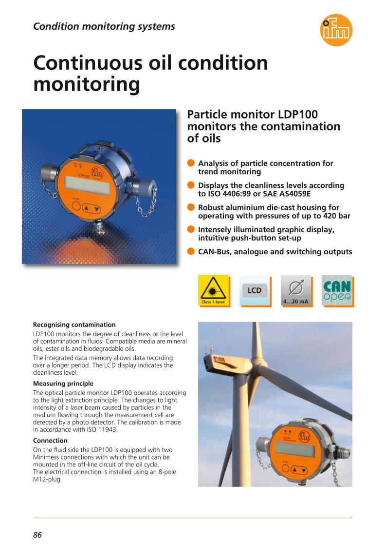
86
Condition monitoring systems
Particle monitor LDP100 monitors the contaminationof oils
Recognising contaminationLDP100 monitors the degree of cleanliness or the levelof contamination in fluids. Compatible media are mineral oils, ester oils and biodegradable oils.The integrated data memory allows data recording over a longer period. The LCD display indicates the cleanliness level.
Measuring principleThe optical particle monitor LDP100 operates accordingto the light extinction principle. The changes to light intensity of a laser beam caused by particles in the medium flowing through the measurement cell are detected by a photo detector. The calibration is madein accordance with ISO 11943.
ConnectionOn the fluid side the LDP100 is equipped with two Minimess connections with which the unit can bemounted in the off-line circuit of the oil cycle. The electrical connection is installed using an 8-poleM12-plug.
Analysis of particle concentration fortrend monitoring
Displays the cleanliness levels accordingto ISO 4406:99 or SAE AS4059E
Robust aluminium die-cast housing foroperating with pressures of up to 420 bar
Intensely illuminated graphic display, intuitive push-button set-up
CAN-Bus, analogue and switching outputs
Continuous oil condition monitoring
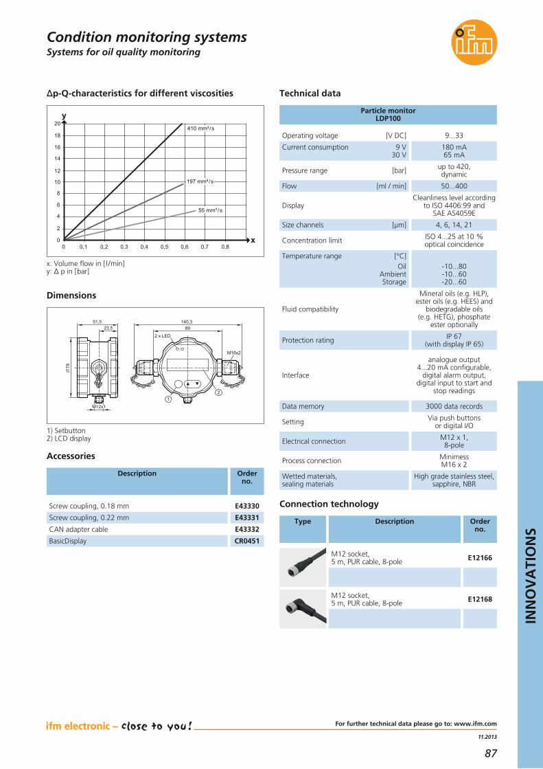
87
11.2013
INN
OV
ATI
ON
S
Condition monitoring systemsSystems for oil quality monitoring
Operating voltage [V DC] 9...33
Current consumption 9 V30 V
180 mA65 mA
Pressure range [bar] up to 420, dynamic
Flow [ml / min] 50...400
DisplayCleanliness level according
to ISO 4406:99 and SAE AS4059E
Size channels [μm] 4, 6, 14, 21
Concentration limit ISO 4...25 at 10 % optical coincidence
Temperature range [°C]Oil
AmbientStorage
-10...80-10...60-20...60
Fluid compatibility
Mineral oils (e.g. HLP),ester oils (e.g. HEES) and
biodegradable oils (e.g. HETG), phosphate
ester optionally
Protection rating IP 67 (with display IP 65)
Interface
analogue output 4...20 mA configurable,
digital alarm output, digital input to start and
stop readings
Particle monitorLDP100
Technical dataΔp-Q-characteristics for different viscosities
Data memory 3000 data records
Setting Via push buttons or digital I/O
Electrical connection M12 x 1, 8-pole
Process connection Minimess M16 x 2
Wetted materials, sealing materials
High grade stainless steel,sapphire, NBR
For further technical data please go to: www.ifm.com
Dimensions
Connection technology
M12 socket,5 m, PUR cable, 8-pole E12168
M12 socket,5 m, PUR cable, 8-pole E12166
Type Description Orderno.
23,551,5
78
140,389
M12x1
2 x LED
12
M16x2
1) Setbutton2) LCD display
410 mm²/s
197 mm²/s
55 mm²/s
10
0,1 0,2 0,3 0,4 0,5 0,6 0,7 0,800
2
4
6
12
14
16
18
20
8
y
x
x: Volume flow in [l /min]y: Δ p in [bar]
Screw coupling, 0.18 mm E43330
Screw coupling, 0.22 mm E43331
CAN adapter cable E43332
BasicDisplay CR0451
Accessories
Description Orderno.

88
32-bit SmartController withhigh protection rating IP 67
High performance at low costifm electronic has launched the SmartController inresponse to market demand for a low-cost mini con-troller for mobile applications. As well as being used asthe main controller for small machines or applications,the 32-bit SmartController is also suited for use as anintelligent I/O module for decentralised preprocessingof sensor signals in complex control systems.
Flexible networkingNetworking of the modules with the CANopen protocolon the powerful CAN bus allows quick implementationof the application. Two integrated CANopen interfacesserve for the flexible and powerful extension of the system with further I/O or control modules. Also, theexchange of SAE J 1939 engine data and CANopendata is easy to carry out via these interfaces.
Analogue and digital I/Os with diagnosticfunction for mobile applications
For use as intelligent I/O module with integrated control function
2 CAN interfaces with CANopen and SAE J1939 protocol
Freely programmable with CODESYS 2.3 to IEC 61131
E1 type approval from the Kraftfahrtbun-desamt (German Federal Motor TransportAuthority)
Cost-optimised mini controllerfor mobile applications
Systems for mobile machines

89
04.2013
INN
OV
ATI
ON
S
For further technical data please go to: www.ifm.com
Mobile controllers
Description Order no.
SmartController, 32 bits, 16 I / 16 O CR2530
Technical data
SmartControllerCR2530
Products
Housing closed metal housing withflange fastening
Device connectionAMP connector
55 poles latched, protectedagainst reverse polarity
Protection IP 67
Operating voltage [V DC] 8...32
Functions and advantages
• Mechanical designAll necessary connections for the inputs and outputs,communication and programming can be made viathe reverse-polarity protected central plug in the con-troller integrated into the compact metal housing
• Powerful electronicsThe integrated 32-bit processor and the electronicsare optimised for mobile applications. The inputs andoutputs can be configured to the application via theuser program. The two-colour status LED displays themost important system messages.
• Configurable inputs/outputsThe inputs / outputs can be freely configured by theuser. Digital inputs, analogue inputs for current orvoltage, inputs with diagnostic capability and fastpulse inputs are available. The outputs can be set asdigital outputs, PWM and current-controlled outputs.
• Programming to IEC 61131-3The CODESYS software enables clear and easy crea-tion of the application software. The SmartControllersupports all common CODESYS programming languages. Simple and clearly structured function libraries are available for communication and specialdevice functions.
• CAN communication interfacesThe SmartController is equipped with two CAN inter-faces to ISO 11898. Using these, data can for examplebe exchanged with a display, further I/O modules oran engine controller. Among others, the interfacessupport the CANopen protocol and the J1939 protocol.The CAN interfaces are also used for programming.To do so, the device electronics are directly and con-veniently activated via the powerful PC interfaceCANfox. Using this, operating system and applicationprogram can be loaded or parameters changed.
Applications:• complex construction machines• attachable units• mini vehicles
Current consumption [mA] ≤ 45 mA
Temperature range operation [°C]storage [°C]
-40...85-40...85
Processor PowerPC 5517E50 MHz
Indicators LED red / green
Inputs (total)digitaldigital, analogue (0...10/32 V, 0...20 mA)digital, frequency (≤ 30 kHz)digital, resistance measurement
166442
Outputs (total)digital, PWM (2 A)digital, PWM, current-controlled (2 A)digital, PWM / analogue 0...10 V, (2 A)digital, PWM (4 A)
1610222
Supported CAN protocolsCANopen
(DS 301 V4.1)SAE J 1939
Standards and tests (extract) CE,E1 (UN/ECE R10)
Systems for mobile machines
Connector, 55 poles (wirable) EC2013
Cable with connector 55 poles, 1.2 m EC2086
Cable with connector 55 poles, 2.5 m, sealed EC2097
Programming software CODESYS, German V2.3 CP9006
Programming software CODESYS, English V2.3 CP9008
Data memory SRAM [kB] 592
Data memory Flash [kB] 1536
Data memory (retain), FRAM [kB] 1

90
32-bit ExtendedControllerwith 64 multifunctional inputsand outputs
ExtendedController for mobile machinesThe mobile controller meets the requirements of modern electronics. The large number of inputs and outputsallows to simultaneously process sensor signals andproportional functions. The controller was developedparticularly for use in off-highway and mobile machineson the basis of the current standards and long-termexperience.
Connection and interfacesBesides the multifunctional inputs and outputs eachcontrol module is equipped with 5 CAN interfaces.They support all important bus protocols, differentbaud rates and also the transparent and preprocesseddata exchange. Programming to IEC 61131-3 ensuresthat all control functions can be easily integrated in theapplication program.
Analogue and digital I /Os with diagnosticfunction for mobile applications
For complex control functions in mobilemachines
5 CAN interfaces with CANopen and SAE J1939 protocol
Freely programmable with CODESYS 2.3to IEC 61131-3
E1 type approval of the Kraftfahrtbundes-amt (German Federal Motor TransportAuthority)
Robust controller for moremobility on wheels and tracks
Systems for mobile machines

91
11.2013
INN
OV
ATI
ON
S
Mobile controllers
Technical dataExtendedController CR0133
HousingClosed metal housing
with flange fastening
Device connectionAMP connector
55 poles latched, protectedagainst reverse polarity
Protection IP 67
Operating voltage [V DC] 8...32
Functions and advantages
• Mechanical designThe control electronics integrated into a compact metal housing provides all necessary connections for theinputs and outputs, communication and programming via the reverse-polarity protected central plugs suitable for mobile applications. The RGB status LED displaysthe most important system messages.
• Powerful electronicsThe core of the controller designed according to the applicable standards for electronics for mobileapplications is a modern 32-bit processor. Monitoringand protection functions enable safe operation evenunder extreme operating conditions. The input / output extension is connected to the maincontroller via a CANopen interface.
• Configurable inputs and outputsBy means of the application software the inputs andoutputs can be configured to adapt to the respectiveapplication.Depending on the type of input, a configuration asdigital, frequency or analogue input with diagnosticfunction or as digital input or input for resistancemeasurement is possible. In addition some of theinputs support the evaluation of positive and negativedigital input signals. The analogue inputs enable bothcurrent and voltage measurement.Most outputs provide a configuration as digital orPWM output with diagnostic capabilities, with andwithout current control.
Programmable to IEC 61131-3 with CODESYSProgramming with the standardised IEC 61131-3languages enables the user to create clear and easyapplication software.In addition, libraries are available for special functionsof the controller.
• CAN-interfaces with CANopen protocolThe controller is equipped with five CAN interfaces toISO 11898. The data is exchanged with all connectedbus participants via these interfaces. The CANopenprotocol enables quick and flexible connection to thebus. For communication with the motor and thepower train all interfaces can be reconfigured to theJ1939 protocol.
Applications:Complex construction machines, agriculturalmachines, municipal vehicles
Current consumption [mA] ≤ 210
Temperature range [°C] -40...85
Indication RGB LED
Controller Infineon TriCore 1796
Number of inputs(configurable)Digital (positive / negative sensor signals)Analogue (0...10 / 32 V, 0...20 mA,ratiometric)Frequency (≤ 30 kHz)Digital (positive / negative sensor signals)Analogue (0...10 / 32 V, 0...20 mA,ratiometric)Digital (positive sensor signals)Resistance measurement(3...690 Ω / 16 Ω...30 kΩ)Digital (positive sensor signals)Frequency (≤ 30 kHz)Digital (positive sensor signals)
12
4
6
4
6
Number of outputs(configurable)Digital, positive / negative switchingPWM output (2/4 A, 3 A, H-bridge)Current-controlled (2/4 A, 3 A)Digital, positive-switching, PWM output (2 A)Current-controlled (2 A)Digital, positive-switching, PWM output (2 A) (2 of which analogue output 0...10 V)Digital, positive-switching, PWM output (4 A)Digital, positive-switching (2 A)
16
2
8
2
4
Sensor supply5 / 10 V DC, 400 mA 1
Interfaces 5 x CAN, 1 x RS2321 x virt. COM port (USB)
Supported CAN protocolsCANopen
(CiA DS 301 V4)SAE J 1939
Program memory [MB] 1,2
Data memory RAM [kB] 256
Data memory FRAM [kB] 48
Data memory non-volatile [kB] 4
Data memory auto-save [kB] 4
Programming software CODESYS V2.3
Standards and tests(extract)
CE,E1 (UN-ECE R10)
EN50155 / EC50121
For further technical details please visit: www.ifm.com
Systems for mobile machines

92
Resistive 7.0" TFT touch display with a resolution of800 x 480 pixels
Dialogue module with touch screenIn almost any mobile machinery a powerful process anddialogue unit is needed for machine operation and forindication of system messages.With its high-resolution graphic display, the powerful32-bit controller and the flexible programming accordingto IEC 61131-3, the PDM360 NG Touch is such a userinterface.The resistive touch display allows easy and intuitivehandling. Its robust housing with protection rating IP 65 / IP 67 enables mounting inside or outside the cabin. Ithas been designed for surface and panel mounting.
ConnectionFour CAN interfaces, Ethernet, USB and video inputtogether with the Linux operating system form a uni-versal platform for networking and communicationwith other vehicle components.As an option, analogue cameras can be connected tohave a view of unmanageable machine areas.
Backlit function keys withtactile feedback
Rocker switch for easy menu navigation
Internal mass storage, USB interface,interfaces for analogue cameras
4 CAN interfaces with CANopen andSAE J1939 protocol
Programmable to IEC 61131-3 withCODESYS 2.3
Dialogue module PDM360 NGTouch for mobile machines
Systems for mobile machines

93
04.2013
INN
OV
ATI
ON
S
For further technical data please go to: www.ifm.com
Description Orderno.
Mounting frame for panel mounting EC2110
USB adapter cable, M12 / RJ45 socket, 1.5 m EC2099
Ethernet, cross-over patch cable, 2 m, PUR cable,M12 connector / RJ45 connector E11898
Programming software CODESYS, German version CP9006
Programming software CODESYS, English version CP9008
Technical data
Dialogue module PDM360 NG TouchCR1082
Products
Housing closed,diecast aluminium
Device connection M12
Protection IP 65, IP 67
Operating voltage [V DC] 10...32
Functions and advantages
• High-resolution displayProtected by a scratch-resistant glass pane, the moderntouch display, which can even be read in sunlight,provides a resolution of 800 x 480 pixels with anaspect ratio of 15:9. Images and graphics can beshown with a colour depth of up to 18 bits.
• Mechanical structureThe PDM360 NG Touch has a fully sealed diecast alu-minium housing with protection rating IP 65 / IP 67.The integrated M12 connectors provide all importantconnections for supply, inputs /outputs and commu-nication. It can be used as surface mount devicesusing the tried-and-tested RAM® mount system orcan be mounted in a wall. The service lid on the backallows the exchange of the battery for the real-timeclock as well as access to the USB 2.0 service inter-face.
• The powerful electronicsThe integrated 32-bit controller and the operating sys-tem Embedded Linux are the basis for the visualisationof the high-resolution graphics, the processing of theapplication program and the unit functions. Embedded Linux furthermore provides many possibili-ties as regards communication and networking withother systems and networks.
• Programming to IEC 61131-3The CODESYS software enables a clear and easy crea-tion of the application software for the user. Functionlibraries are available for the special functions of thetouch display.The graphic elements are created via the integratedvisualisation editor and can be selected by touchingthe screen.
• The communication interfacesThe PDM360 NG Touch is equipped with four CAN interfaces to ISO 11898. They support the CANopenand the J1939 protocol among others. The integratedUSB 2.0 interfaces provide easy data exchange withmodern storage media.The Ethernet interface cannot only be used for pro-gramming but also for communication with othernetwork participants.
• VersionsOther PDM 360 NG variants without touch functionare also available, for example with an encoder fordata entry or with an analogue video input for directconnection to a camera.
Applications:• Complex construction machines• Agricultural machines• Municipal vehicles
Current consumption [mA] ≤ 300
Temperature range operation [°C]storage [°C]
-30...65-30...80
7" TFT LCD colour display 800 x 480 pixels18-bit colour depth
Indication RGB LED
Processor MPC5121/ PPC, 400 MHz
Data memory Flash / SRAM [MB] 128 / 128
Internal mass storage [GB] 1
Operating elements pushbuttons(backlit) rocker switch
91
Inputs 1 x digital / analogue
Inputs with special functions:Internal temperature sensorsPhotoelectric sensor
11
Outputs 1 x digital, 1 x buzzer
Interfaces4 x CAN
1 x Ethernet 100 Mbits2 x USB 2.0
Camera interfacesCR1083, CR1084, CR1085
2 x video input foranalogue camera
Supports CAN protocols CANopen (DS 301 V4)SAE J 1939
Programming software CODESYS V2.3
Standards and tests(extract)
CE,E1 (UN/ECE R10),
EN 50 155
Dialogue modules / displaysSystems for mobile machines
PDM360 NG touch display with rocker switch, 9 function keys and video input CR1082
Touch screen5-wire, resistive
Input tool: stylus pen or finger

94
For users in factory automationand the machine tool industry
ecolink –The new dimension in connection technology.
ecolink M12 for standard applicationsMost applications require special solutions. Only reliableproduction processes and faultless assembly lead tosuccess in the long run.The integrated end stop protects the O-ring against destruction caused by over-tightening the nut. No toolsneeded for installation and removal.The asymmetrically acting vibration protection holdsthe coupling nut tight in its position ensuring a lowcontact resistance between the nut of the connectorand the housing of the connected device. This is extremely important for permanently high protection against strong noise interference.
Connection technology meets the M12standard (EN 61076)
The mechanical end stop protects the O-ring against destruction
Permanent vibration protection with sawtooth contour
Continuously high EMC interference protection
ecolink – the reliable connection evenwith strong noise field interference
Connection technology

95
11.2013
INN
OV
ATI
ON
S
Sockets
For further technical details please visit: www.ifm.com
Connection technology
Technical data:Operating voltage:4 poles: 50 V AC / 60 V DC5 poles: 30 V AC / 36 V DCNominal current: 4 AProtection:Screen not connected: IP 65, IP 67, IP 68, IP 69K / IIIScreen connected: IP 65, IP 67 / IIIIn locked condition with the matching counterpart.Tightening torque nut: 0.6...1.5 NmNote the maximum value of the counterpart.Ambient temperature:-25...90 °C, cable firmly laid-25...90 °C, cable movedCable characteristics:Drag chain, 2 million cycles
Materials:Housing / moulded body: TPUContact carrier: TPUCoupling nut: Nickel-plated brassContacts: Gold-platedSealing ring: VitonCable: PUR halogen-free, shielded, 4 x 0.34 mm2, Ø 4.9 mm5 x 0.25 mm2, Ø 4.9 mm
Approvals:cRUus in preparation
Dimensions
15,5
M12x1 45
14
Example EVC526
15,5
M12x1 36,5
26,5
14
Example EVC529
Type Connection /cable
Orderno.
Number ofpoles
Screen not connected
2.0 m EVC526
5.0 m EVC527
10.0 m EVC528
4
4
4
2.0 m EVC529
5.0 m EVC530
10.0 m EVC531
4
4
4
Shielding characteristics
2.0 m EVC532
5.0 m EVC533
10.0 m EVC534
5
5
5
2.0 m EVC535
5.0 m EVC536
10.0 m EVC537
5
5
5
Screen connected
2.0 m EVC538
5.0 m EVC539
10.0 m EVC540
4
4
4
2.0 m EVC541
5.0 m EVC542
10.0 m EVC543
4
4
4
2.0 m EVC544
5.0 m EVC545
10.0 m EVC546
5
5
5
2.0 m EVC547
5.0 m EVC548
10.0 m EVC549
5
5
5
y
x-70
-60
-50
-40
-30
-20
-10
0
10 100 10001
x: Frequency in [MHz]y: Shielding characteristics in [dB]

96
The low-cost alternative foruse in factory automation
ecolink –a new dimension in connection technology.
ecolink M12 for standard applicationsMost applications require special solutions. Only assuredproduction processes and faultless assembly lead tosuccess in the long run.The integrated end stop protects the O-ring against destruction caused by over-tightening the nut. No toolsneeded for installation and removal.The asymmetrically acting vibration protection holdsthe nut tight in its position, guaranteeing an optimumand permanent seal.
Connection technology meets the M12standard (EN 61076)
The mechanical end stop protects the O-ring against destruction
Permanent vibration protection with saw tooth contour
LEDs clearly visible even under brightlighting
ecolink M12, the secure connectionfor standard applications
Connection technology

97
04.2013
INN
OV
ATI
ON
S
For further technical data please go to: www.ifm.com
SocketsConnection technology
Technical data:Operating voltage:without LED: 250 V AC / 300 V DCwith LED: 10...36 V DCNominal current: 3 AProtection: IP 65, IP 67
in locked condition with the matching counterpart.
Tightening torque nut: 0.6...1 Nm(note the maximum value of the counterpart!)Ambient temperature:-25...70 °C, firmly laid5...70 °C, movedCable characteristics:conditionally suitable for drag chains
Materials:Housing / moulded body: TPUContact carrier: TPUCoupling nut: diecast zinc, nickel-platedContacts: gold-platedSealing ring: VitonCable: PVC, 3 x 0.25 mm2, Ø 4.5 mm
Approvals:cRUus in preparation
Dimensions
15,5
M12x1 45
14
Example EVS001
15,5
M12x1 36,5
26,5
14
Example EVS004
15,5
M12x1 36,5
26,5
143 LED
Example EVS007
Type Description Order no.
NEW
LED
M12 sockets
2.0 m EVS001
5.0 m EVS002
10.0 m EVS003
–
–
–
2.0 m EVS004
5.0 m EVS005
10.0 m EVS006
–
–
–
2.0 m EVS007
5.0 m EVS008
10.0 m EVS009
•
•
•

98
Compact low-profile M8 splitters for confined spaces
ecolink –a new dimension in connection technology.
Small design – maximum protectionIn particular where space is at a premium, e.g. in robotics,handling and assembly technology, most applicationsrequire special solutions. Here the new, lean and flatM8 splitter with the tried-and-tested safe ecolink technology is a convincing solution. Only high-qualitymaterials, safe production processes and fault-free in-stallation ensure high machine uptime in the long run.
ecolink technologyThe new ecolink technology prevents incorrect moun-ting. An integrated mechanical end stop protects theO-ring from destruction. So, rapid and secure installa-tion is possible without an expensive torque wrench.
O-ring protection by a mechanical end stop
Perfect ingress resistance even whenmounted without tools
High-quality materials for permanent reliability
Connection technology meets the M8 standard (EN 61076)
Little space required due to lean and flat design
Small but effective – M8 splitterswith secure ecolink connection
Connection technology

99
04.2013
INN
OV
ATI
ON
S
For further technical data please go to: www.ifm.com
Splitter boxes
Technical data:Operating voltage: with LED 10...30 V DCNominal current:total max. current rating 6 Amax. 2 A per locationwith M12 connectiontotal max. current rating 2 Amax. 2 A per locationProtection: cable connection IP 65, IP 67, IP 68
connector IP 65, IP 67in locked condition with the matching counterpart.
Tightening torque M8 connector: 0.3...0.6 Nm,adhere to the maximum value of the counterpartAmbient temperature: -25...80 °C
Materials:Housing: PURContact carrier: PAFitting: CuZn/NiContacts: gold-platedSealing ring: VitonCable: PUR, halogen-free
Applications:Factory automation, machine tools, hydraulics
M8x1
17
20
4,5
4,5
3016
129,
5 101
4,3
1122
Dimensions
Example EBC066
Splitter with cable connection · LED · PNP
Splitter with M12 connection · LED · NPN
4
Splitter with M16 connection · LED · NPN
2 and 4
44
2 and 42 and 4
44
2 and 42 and 4
4
Type Signals on pin
Order no.
NEW
Connection/Cable[m]
Connection technology
Splitter with M12 connection · LED · PNP
2 and 4
Splitter with M16 connection · LED · PNP
Splitter with cable connection · LED · NPN
44
2 and 42 and 4
44
2 and 42 and 4
Type Signals on pin Order no.
NEW
Connection/Cable[m]
M12x1
17
23,7
4,5
4,5
3016
85,4
574,
3
M8x1
1122
Example EBC050EBC060
EBC063
–
–
EBC048
EBC051EBC049
EBC052
510510
EBC054
EBC056EBC055
EBC057
510510
–
–
EBC050
EBC053
EBC058
EBC061EBC059
EBC062
EBC064
EBC066EBC065
EBC067
510510
510510
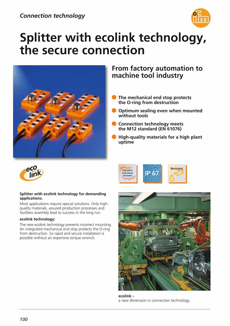
100
From factory automation tomachine tool industry
ecolink –a new dimension in connection technology.
Splitter with ecolink technology for demandingapplications.Most applications require special solutions. Only high-quality materials, assured production processes andfaultless assembly lead to success in the long run.
ecolink technology:The new ecolink technology prevents incorrect mounting.An integrated mechanical end stop protects the O-ringfrom destruction. So rapid and secure installation ispossible without an expensive torque wrench.
The mechanical end stop protectsthe O-ring from destruction
Optimum sealing even when mountedwithout tools
Connection technology meetsthe M12 standard (EN 61076)
High-quality materials for a high plantuptime
Splitter with ecolink technology,the secure connection
Connection technology

101
04.2013
INN
OV
ATI
ON
S
For further technical data please go to: www.ifm.com
Splitter boxes
Technical dataOperating voltage:without LED 30 V AC / DCwith LED 10...30 V DCNominal current:total max. current rating 12 Amax. 4 A per locationProtection rating: IP 65, IP 67, IP 68
in locked condition with the matching counterpart
Tightening torque M12 connector: 0.6...1.5 Nm,Note the maximum value of the connectorAmbient temperature: -25...80 °C, -5...60 °C for flexible cablingCable characteristics: drag chain > 2 million cyclesBending radius for flexible use:min. 10 x cable diameter
Materials:Housing: PAM12 connector: CuZn / NiContacts: gold-platedSealing ring: VitonCable: PUR, halogen-free
Applications:Factory automation, machine tools, hydraulics
Dimensions
Example EBC017
Splitter with cable connection
Splitter with M23 connection
EBC001
EBC003
M23EBC002M23
M23EBC004
EBC009
EBC011EBC010
EBC012
M23
Type Signalson
contact
Connection Orderno.
44
2 and 42 and 4
LED
–•–•
EBC005
EBC007
M23EBC006M23
M23EBC008M23
44
2 and 42 und 4
–•–•
M23M23M23M23
44
2 and 42 and 4
–•–•
EBC013
EBC015
5EBC02510
5EBC02710
4444
––••
EBC014
EBC016
5EBC02610
5EBC02810
2 and 42 and 42 and 42 and 4
––••
EBC017
EBC019
5EBC02910
5EBC03110
4444
––••
EBC018
EBC020
5EBC03010
5EBC03210
2 and 42 and 42 and 42 and 4
––••
EBC021
EBC023
5EBC03310
5EBC03510
4444
––••
EBC022
EBC024
5EBC03410
5EBC03610
2 and 42 and 42 and 42 and 4
––••
Type Signalson
contact
Connection/Cable[m]
Orderno.
LED
Connection technology
1 2
43
65
18
4,7
7310
0
22
54,
5
3339
54
M12x132,7
27
1 2
43
18
4,7
7312
7
22
54,
5
3339
54
M12x1
5
32,7
2734
6
8
5
7
Example EBC024

102
*Some offered information is available country-specific.
www.ifm.comInformation around the clock andaround the globe in 23 languages on the internet.
• Information- product innovations- company news- exhibition info- locations- jobs
• Documentation- data sheets- operating instructions- manuals- approvals- CAD data
• Communication*- request for documents- recall service- live advice- newsletter
• Selection- interactive product selection aids- configuration tools- data sheet direct
• Animation- virtual product animations- flash movies (video sequences)
• Application- applications- product recommendations- calculation aids
• Transaction*- e-shop processing- e-procurement catalogues

103
Convenient order processingvia the e-shop** on the internet.
Secured authentication
Customer-related priceindication
Real time availability check
Personal product favourites
Online parcel tracking
Individual order history
Convenient quick input form
Simple order processing
Management of shippingaddresses
Confirmations by e-mail
**Already available in many countries.

Visit our website:
www.ifm.com
ifm electronic gmbhFriedrichstraße 145128 EssenTel. +49 / 201 / 24 22-0Fax +49 / 201 / 24 22-1200E-mail [email protected]
Position sensors
Sensors formotion control
Industrial imaging
Safety technology
Process sensors
Condition monitoringsystems
Industrialcommunication
Identification systems
Systems formobile machines
Connectiontechnology
Overviewifm product range:
Accessories
Over 70 locations worldwide –at a glance at www.ifm.com
ifm a
rtic
le n
o. 7
8000
318
· We
rese
rve
the
right
to
mak
e te
chni
cal a
ltera
tions
with
out
prio
r no
tice.
· Pr
inte
d in
Ger
man
y on
non
-chl
orin
e bl
each
ed p
aper
. 10
/13
Cert no. IMO-COC-027827