ifj’kks/ku- - Indian Railway · Page 2 of 20 File No. EL/7.1.108/Transformer Specification No....
20
Page 1 of 20 File No. EL/7.1.108/Transformer Specification No. RDSO/PE/SPEC/ AC/0080 -2007 (Rev.1) DRAFT Prepared by ADE/Electrical Checked by DSE(TL-AC System Design) lR;eso t;rs Hkkjr ljdkj jsy ea=ky; GOVERNMENT OF INDIA MINISTRY OF RAILWAYS vuqla/kku vfHkdYi ,oa ekud laxBu jsy ea=ky; RESEARCH DESIGNS AND STANDARDS ORGANISATION MINISTRY OF RAILWAYS ,y0,p0ch0 izdkj ds ,-lh- bZ vks th fMCcksa @ ikoj dkj esa iz;qDr gksus okys 60 ds0oh0,0 750@415oksYV] 3 Qst forjÆ VkaªlQkeZj dh fof’kf"V SPECIFICATION FOR 60 KVA, 750V/415V, 3- PHASE DRY TYPE DISTRIBUTION TRANSFORMER FOR LHB TYPE AC EOG COACHES/POWER CAR vkj-Mh-,l-vks-@ih-bZ-@,l ih bZ lh@,-lh-@0080 &2007, (ifj’kks/ku-1½ RDSO/PE/SPEC/ AC/0080 -2007 (Rev.1) S. No. Date of amendment Revision Reason vuqeksfnr APPROVED dk;Zdkjh funs’kd@ih ,l ,.M bZ ,e ;w ED/PS &EMU
Transcript of ifj’kks/ku- - Indian Railway · Page 2 of 20 File No. EL/7.1.108/Transformer Specification No....

Page 1 of 20 File No. EL/7.1.108/Transformer
Specification No. RDSO/PE/SPEC/ AC/0080 -2007 (Rev.1) DRAFT
Prepared by ADE/Electrical
Checked by DSE(TL-AC System Design)
lR;eso t;rs
Hkkjr ljdkj jsy ea=ky;
GOVERNMENT OF INDIA MINISTRY OF RAILWAYS
vuqla/kku vfHkdYi ,oa ekud laxBu jsy ea=ky;
RESEARCH DESIGNS AND STANDARDS ORGANISATION MINISTRY OF RAILWAYS
,y0,p0ch0 izdkj ds ,-lh- bZ vks th fMCcksa @ ikoj dkj esa iz;qDr gksus okys 60 ds0oh0,0 750@415oksYV] 3 Qst forjÆ VkaªlQkeZj dh fof’kf"V
SPECIFICATION FOR 60 KVA, 750V/415V, 3- PHASE DRY TYPE DISTRIBUTION
TRANSFORMER FOR LHB TYPE AC EOG COACHES/POWER CAR
vkj-Mh-,l-vks-@ih-bZ-@,l ih bZ lh@,-lh-@0080 &2007, (ifj’kks/ku-1½
RDSO/PE/SPEC/ AC/0080 -2007 (Rev.1)
S. No. Date of amendment Revision Reason
vuqeksfnr APPROVED
dk;Zdkjh funs’kd@ih ,l ,.M bZ ,e ;w ED/PS &EMU

Page 2 of 20 File No. EL/7.1.108/Transformer
Specification No. RDSO/PE/SPEC/ AC/0080 -2007 (Rev.1) DRAFT
Prepared by ADE/Electrical
Checked by DSE(TL-AC System Design)
SPECIFICATION FOR 60 KVA, 750 V/415V, 3- PHASE DRY TYPE DISTRIBUTION
TRANSFORMER FOR LHB TYPE AC EOG COACHES/POWER CAR
FOREWORD: EOG AC coaches/Power car/Pantry Car requires 750 V/415 V step down transformer for coach power supply. Their capacity requirement is 60 KVA and these transformers are mounted underslung.
1.0 SCOPE:
The specification covers the design, manufacture, test, supply requirements of 60 KVA, 750V/415V, 3-phase dry type air-cooled power distribution transformer. The transformer shall be installed on the under frame of the coach/power car on LHB type EOG AC coaches/power car/ Pantry car.
2.0 SCOPE OF SUPPLY: 2.1 The scope of supply of each transformer shall include the following:-
i) 60 KVA, 3 Phase, Star -Star (YY) 750V/415V transformer including terminal Board assembly consisting of terminal
Stud etc. 1 No.
ii) Anti-vibration mountings (loose supply) 4 No.
iii) Drawings and circuit diagram along with trouble shooting 1 No. instructions
3.0 SERVICE CONDITION: 3.1 The transformer shall be sturdy and suitable for the following service conditions
normally encountered on the Railway rolling stock, under climatic conditions existing throughout India.
Ambient -4 to 55 deg C Average ambient 35 deg. C Train speed 200 Km/h Relative Humidity Up to 95% Altitude Max 1200 m above sea level Atmosphere Extremely dusty and desert weather and desert terrain in
certain areas. The dust contents in the air may reach as high value as 1.6 mg/cubic meter. Very dusty atmosphere with fog, cast iron dust of brake block shoe, flying ballast etc.
Annual rain fall Very heavy in certain areas: between 1750 to 6250 mm. Coastal area The equipment shall be designed to work in humid salt
laden and corrosive atmosphere. The maximum values of the condition shall be as under : Maximum pH value 8.5
Page 3 of 20 File No. EL/7.1.108/Transformer
Specification No. RDSO/PE/SPEC/ AC/0080 -2007 (Rev.1) DRAFT
Prepared by ADE/Electrical
Checked by DSE(TL-AC System Design)
Sulphate 7 mg/liter Max. concentration 6 mg/liter of chlorine Max. conductivity 130 micro siemens/CM
Shocks and Vibration
The transformer shall withstand satisfactorily vibrations and shocks normally encountered in service as indicated below: a) Min. vertical acceleration - 3.0 g b) Min. lateral acceleration - 3.0 g c) Min. longitudinal acceleration - 3.0 g (‘g’ being the value of acceleration due to gravity)
4.0 GOVERNING STANDARDS / SPECIFICATIONS: 4.1 Reference shall be made to following standard / specifications
UIC 564-2 Regulation relating to fire protection and fire fighting measures in passenger carrying railway vehicles or assimilated vehicles used on international service
IEC 60529 Degree of protection provided by enclosures IEC-61373 Railway applications-Rolling stock equipment-shock and
vibration tests IS:2062-1999 Steel for general structure purpose. IS:2026 (PART-I) Specification for power transformers: General IS: 2026 (PART-II) Specification for power transformers: Temperature Rise IS: 2026 (PART-III) Specification for power transformers: Insulation level and
dielectric tests IS: 2026 (PART-IV) Specification for power transformers: Terminal marking,
tapping and connections IS: 11171 Specification for Dry type Power transformers IS: 1885 (Pt. XXXVIII)
Electro-technical vocabulary for transformers
IS: 1271-85 Thermal evaluation and classification of electrical insulation.
IS: 2551-1982 Danger Notice Plate IS: 13730, Pt 13 -93 “Part 13, Polyester or polyesterimide over coated with
polymide-imide enameled round copper wire, Class 200. IS:13730, Pt. 29 Specification for particular types of winding wires “Part 2,
Polyester or polyesterimide over coated with polymide-imide enameled rectangular copper wire, Class 200.
IS: 3024-1997 Specification for electrical steel sheet (oriented). CRGO IS: 1363-84 (Part II) Hex. Hd. Screws (M5-M36) IS: 649-1997 Method of testing steel sheets for magnetic circuits of
power electrical apparatus IS: 6911-92 Stainless steel plate, sheet and strips
Note: Latest version of the above specifications/standards shall be applicable and
should be available with the manufacturer/supplier.

Page 4 of 20 File No. EL/7.1.108/Transformer
Specification No. RDSO/PE/SPEC/ AC/0080 -2007 (Rev.1) DRAFT
Prepared by ADE/Electrical
Checked by DSE(TL-AC System Design)
4.2 Any deviation from this specification proposed by the firm to improve upon the performance, utility and efficiency of the transformer shall be given due consideration, provided full particulars of the deviations with justification are furnished. In case of any contradiction between the provisions of above standards, the details mentioned in this specification shall prevail.
5.0 SUPPLIER’S RESPONSIBILITY:
5.1 The transformer shall be suitable for rugged service conditions normally to be met
within Railway Rolling Stock, where coaches are expected to run up to a maximum speed of 200 kmph in varying climatic conditions existing throughout India, as mentioned in clause 3.0 of this specification.
5.2 The supplier shall be fully responsible for ensuring that all equipments forming part of
the supply is entirely fit for the purpose and no part of this specification shall in any way remove or reduce this obligation in this respect. In addition, it is the supplier’s responsibility to underwrite the complete design and ensure that it is compatible with and will, in no way, compromise the design and performance of transformer of his supply.
5.3 The supplier shall provide “In the field” service support during the guarantee period.
5.4 The supplier shall supply any purpose built or special tools or equipment that may be
necessary for the correct operation, servicing, testing or installation of the transformer.
5.5 The supplier shall provide assistance, both material and technical, in the installation of the system as a whole to ensure that when it is installed as part of the integrated vehicle system, the performance of the transformer meets or exceeds the requirements specified.
5.6 Should the transformer fail to achieve the requirements, then it shall be modified at the supplier’s expense and within a time scale to be agreed with purchaser/consignee/RDSO.
6.0 TERMINOLOGY:
6.1 For the purpose of this standard, the definition as given in IS: 1885 (Pt. XXXVIII)
(Electro-technical vocabulary for transformers) shall apply.
7.0 TECHNICAL REQUIREMENTS:
7.1 The technical requirement of the transformer shall be as under:
KVA Rating 60 kVA Nominal input voltage 3 Phase, 4 wire, 750 V ± 5% (line to line), 50Hz ±3%,THD
<10%
Nominal output voltage
3 Phase, 4 wire, 415 V ± 5% (line to line), 50Hz ±3%,
Nominal input line current
46.2 A at 750V
Nominal output 83.5 A at 415V

Page 5 of 20 File No. EL/7.1.108/Transformer
Specification No. RDSO/PE/SPEC/ AC/0080 -2007 (Rev.1) DRAFT
Prepared by ADE/Electrical
Checked by DSE(TL-AC System Design)
current Class of insulation H Efficiency >96% from half load to full load Noise level <60db at 1.0 m distance Maximum % impedance UCC overall impedance
4% (max.)
Protection level Stainless steel housing and terminal box
IP-67
Vector configuration Star -Star (Yy) Winding wire Super enameled copper winding wire as per to IS: 13730
Pt. 13, 13730 Pt. 29 Max. temp. rise 115ºC Total weight 500 kg (maximum)
8.0 CONSTRUCTION: 8.1 Over all dimensions, construction and mounting of the transformer shall confirm to 60
KVA transformer enclosure RCF drawing no. CC71216 with latest alteration. Terminal board of the transformer shall be as per RCF drawing no. CC71217 with latest alteration.
8.2 The manufacturer shall take prior approval of enclosure & terminal board drawing,
which shall be in line with RCF drawing mentioned above. 8.3 The enclosure shall meet the requirement of water immersion and dust ingress test
as per IP 67 protection level to IEC60529. 8.4 Anti-vibration mountings 4 Nos. of Resistoflex/Dunlop/Metallestic or other make with
prior approval of RDSO. Shore hardness of AVM shall be 60 and to be supplied loose with the transformer. Mounting holes of the anti-vibration mountings shall match with the foot print of RCF drawing no. CC71216.
8.5 Housing shall be made of stainless steel to grade no. SS-304 (2.0 mm thick) of IS:
6911. 8.6 The manufacturer shall take prior approval of the manufacturing drawing from RDSO
before developing prototype of the transformer. 8.7 The suitable clearance between the terminal stud shall be kept. In this regard, firms
shall furnish the detailed drawing of terminal board indicating the dimensions. 8.8 The clearance and creepage distance shall be maintained as per IS: 13947-1993
with pollution degree 3 for material group –II. 8.9 Acoustic noise level has to be recorded during no load test at a distance of 1.0
meters in all four directions without having nearby moving electrical appliances like fans, exhaust fan etc. It should not be more than 60 dB, when measured as per NEMA standard-2”
Page 6 of 20 File No. EL/7.1.108/Transformer
Specification No. RDSO/PE/SPEC/ AC/0080 -2007 (Rev.1) DRAFT
Prepared by ADE/Electrical
Checked by DSE(TL-AC System Design)
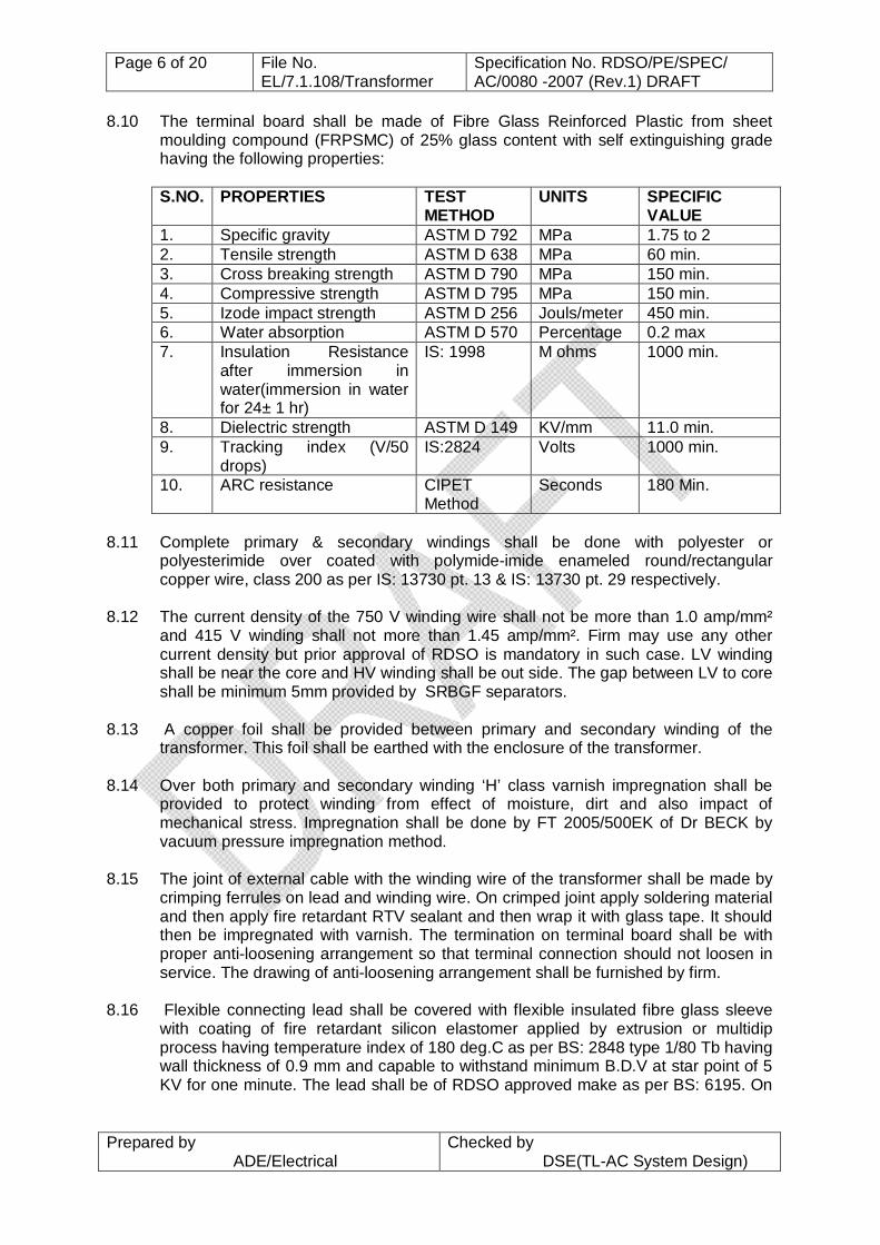
8.10 The terminal board shall be made of Fibre Glass Reinforced Plastic from sheet moulding compound (FRPSMC) of 25% glass content with self extinguishing grade having the following properties:
S.NO. PROPERTIES TEST
METHOD UNITS
SPECIFIC VALUE
1. Specific gravity ASTM D 792 MPa 1.75 to 2 2. Tensile strength ASTM D 638 MPa 60 min. 3. Cross breaking strength ASTM D 790 MPa 150 min. 4. Compressive strength ASTM D 795 MPa 150 min. 5. Izode impact strength ASTM D 256 Jouls/meter 450 min. 6. Water absorption ASTM D 570 Percentage 0.2 max 7. Insulation Resistance
after immersion in water(immersion in water for 24± 1 hr)
IS: 1998 M ohms 1000 min.
8. Dielectric strength ASTM D 149 KV/mm 11.0 min. 9. Tracking index (V/50
drops) IS:2824 Volts 1000 min.
10. ARC resistance CIPET Method
Seconds 180 Min.
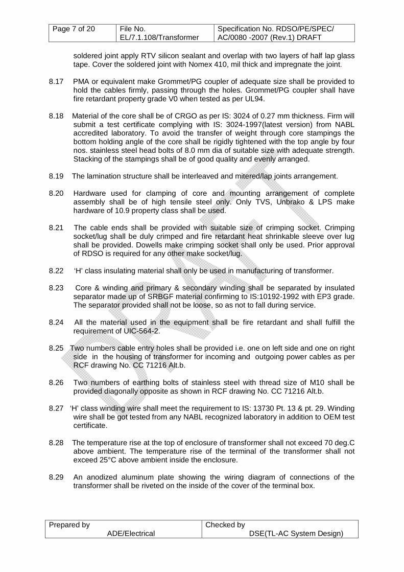
8.11 Complete primary & secondary windings shall be done with polyester or
polyesterimide over coated with polymide-imide enameled round/rectangular copper wire, class 200 as per IS: 13730 pt. 13 & IS: 13730 pt. 29 respectively.
8.12 The current density of the 750 V winding wire shall not be more than 1.0 amp/mm²
and 415 V winding shall not more than 1.45 amp/mm². Firm may use any other current density but prior approval of RDSO is mandatory in such case. LV winding shall be near the core and HV winding shall be out side. The gap between LV to core shall be minimum 5mm provided by SRBGF separators.
8.13 A copper foil shall be provided between primary and secondary winding of the
transformer. This foil shall be earthed with the enclosure of the transformer. 8.14 Over both primary and secondary winding ‘H’ class varnish impregnation shall be
provided to protect winding from effect of moisture, dirt and also impact of mechanical stress. Impregnation shall be done by FT 2005/500EK of Dr BECK by vacuum pressure impregnation method.
8.15 The joint of external cable with the winding wire of the transformer shall be made by
crimping ferrules on lead and winding wire. On crimped joint apply soldering material and then apply fire retardant RTV sealant and then wrap it with glass tape. It should then be impregnated with varnish. The termination on terminal board shall be with proper anti-loosening arrangement so that terminal connection should not loosen in service. The drawing of anti-loosening arrangement shall be furnished by firm.
8.16 Flexible connecting lead shall be covered with flexible insulated fibre glass sleeve
with coating of fire retardant silicon elastomer applied by extrusion or multidip process having temperature index of 180 deg.C as per BS: 2848 type 1/80 Tb having wall thickness of 0.9 mm and capable to withstand minimum B.D.V at star point of 5 KV for one minute. The lead shall be of RDSO approved make as per BS: 6195. On
Page 7 of 20 File No. EL/7.1.108/Transformer
Specification No. RDSO/PE/SPEC/ AC/0080 -2007 (Rev.1) DRAFT
Prepared by ADE/Electrical
Checked by DSE(TL-AC System Design)
soldered joint apply RTV silicon sealant and overlap with two layers of half lap glass tape. Cover the soldered joint with Nomex 410, mil thick and impregnate the joint.
8.17 PMA or equivalent make Grommet/PG coupler of adequate size shall be provided to
hold the cables firmly, passing through the holes. Grommet/PG coupler shall have fire retardant property grade V0 when tested as per UL94.
8.18 Material of the core shall be of CRGO as per IS: 3024 of 0.27 mm thickness. Firm will
submit a test certificate complying with IS: 3024-1997(latest version) from NABL accredited laboratory. To avoid the transfer of weight through core stampings the bottom holding angle of the core shall be rigidly tightened with the top angle by four nos. stainless steel head bolts of 8.0 mm dia of suitable size with adequate strength. Stacking of the stampings shall be of good quality and evenly arranged.
8.19 The lamination structure shall be interleaved and mitered/lap joints arrangement. 8.20 Hardware used for clamping of core and mounting arrangement of complete
assembly shall be of high tensile steel only. Only TVS, Unbrako & LPS make hardware of 10.9 property class shall be used.
8.21 The cable ends shall be provided with suitable size of crimping socket. Crimping
socket/lug shall be duly crimped and fire retardant heat shrinkable sleeve over lug shall be provided. Dowells make crimping socket shall only be used. Prior approval of RDSO is required for any other make socket/lug.
8.22 ‘H’ class insulating material shall only be used in manufacturing of transformer. 8.23 Core & winding and primary & secondary winding shall be separated by insulated
separator made up of SRBGF material confirming to IS:10192-1992 with EP3 grade. The separator provided shall not be loose, so as not to fall during service.
8.24 All the material used in the equipment shall be fire retardant and shall fulfill the
requirement of UIC-564-2. 8.25 Two numbers cable entry holes shall be provided i.e. one on left side and one on right
side in the housing of transformer for incoming and outgoing power cables as per RCF drawing No. CC 71216 Alt.b.
8.26 Two numbers of earthing bolts of stainless steel with thread size of M10 shall be
provided diagonally opposite as shown in RCF drawing No. CC 71216 Alt.b. 8.27 ‘H’ class winding wire shall meet the requirement to IS: 13730 Pt. 13 & pt. 29. Winding
wire shall be got tested from any NABL recognized laboratory in addition to OEM test certificate.
8.28 The temperature rise at the top of enclosure of transformer shall not exceed 70 deg.C
above ambient. The temperature rise of the terminal of the transformer shall not exceed 25°C above ambient inside the enclosure.
8.29 An anodized aluminum plate showing the wiring diagram of connections of the
transformer shall be riveted on the inside of the cover of the terminal box.

Page 8 of 20 File No. EL/7.1.108/Transformer
Specification No. RDSO/PE/SPEC/ AC/0080 -2007 (Rev.1) DRAFT
Prepared by ADE/Electrical
Checked by DSE(TL-AC System Design)
8.30 A danger notice plate of suitable size confirming to IS: 2551 indicating danger voltage 750 V ac shall be riveted on the outside of the terminal box.
9.0 MARKING: 9.1 The following data shall be marked on the nameplate. The data shall be screen
printed in permanent nature on the name plate.
1. Manufacturers name 2. Serial number 3. Year and month of manufacture 4. Capacity/Rating & % impedance 5. Primary & Secondary voltage & current and Frequency 6. Connection diagram (Primary & Secondary) 7. Vector symbol 8. Weight 9. Specification No.
10.0 TESTS: 10.1 Only after the drawings and the design have been approved and the clearance
given to this effect, the manufacturer shall take up the manufacture of the prototype. It is to be clearly understood that any changes, required to be done in the prototype or any additional tests other than specified herein are required to be conducted on the prototype unit or its components, they shall be done expeditiously. During the process of manufacture of the equipment, if the purchaser so desires, he may conduct/repeat any of the routine or additional tests to satisfy himself that the quality of the product being manufactured is of the required standards.
10.2 The type tests shall be carried out by RDSO representative on prototype unit either
totally or in part under the following conditions without any additional cost: (a) A manufacturer undertakes to manufacture for the first time as per this specification.
(b) An important change in design details of machine has been introduced. (c) Specification is modified necessitating the re-designing of equipment. (d) Unsatisfactory performance reported from user Railways. (e) Resumption of production after an interruption of more than two years.
Investigation tests are intended to obtain additional information regarding performance of the production. They shall be specially requested either by the user or by the manufacturer.
RDSO may conduct surprise check on manufacturing process and quality control along with any of the tests to ensure quality of product and its conformance to RDSO specification.
10.3 The suitability of the transformer shall be ascertained by inspection, bench test at the firm’s works, in the stationary coach and during service of the unit on the coach.
10.4 Because of inevitable difference in basic material and variation in manufacture, as
well as measurement error, the value obtained on test may differ from the calculated
Page 9 of 20 File No. EL/7.1.108/Transformer
Specification No. RDSO/PE/SPEC/ AC/0080 -2007 (Rev.1) DRAFT
Prepared by ADE/Electrical
Checked by DSE(TL-AC System Design)
value and tolerances on guaranteed value necessary. The table 7 to IS:2026 (pt. I) gives tolerances to be applied to certain rated quantities when they are the subject to manufacturer guarantees referring in IS:2026 (Pt. I) where the tolerance in one direction is omitted, there is no restriction on the value in the direction.
10.5 The transformer shall be considered as complying with the standard when the
quantities subject to tolerances are not out side the tolerances given in table 7 to IS: 2026 (Pt. I).
10.6 Test format for recording of test results during routine & acceptance test shall be
available with the firm. 10.7 Type test: 10.7.1 All the type tests mentioned in Clause 10.10.1 shall be carried on a prototype unit.
The firm manufacturing for the first time shall get prototype approved from RDSO. Before offering the prototype for type testing, firm will submit internal test results along with drawings of transformer indicating over all, mounting, thickness of sheet/channel & other important dimensions to RDSO for approval.
10.8 Acceptance Test: 10.8.1 Acceptance tests mentioned in clause 10.10.1 shall be carried out by an inspecting
authority nominated by the purchaser at the works of the manufacturer on the sample picked up as per sampling plan by the inspecting authority
10.9 Routine test: 10.9.1 Routine tests mentioned in Clause 10.10.1 shall be carried out on each unit by the
manufacturer at his premises to ensure compliance with the specification and drawings. These test results shall be produced before Indian Railway representative, if demanded. All the tests shall be carried out at firm’s premises at manufacturer’s cost. Inspecting officer shall witness the tests on each unit. A copy of these internal tests conducted by the firm shall be supplied to the inspecting/purchasing authority. Not withstanding above, RDSO reserves the right to have these equipments also tested as per this specification at any reputed test house in India at firm’s cost.
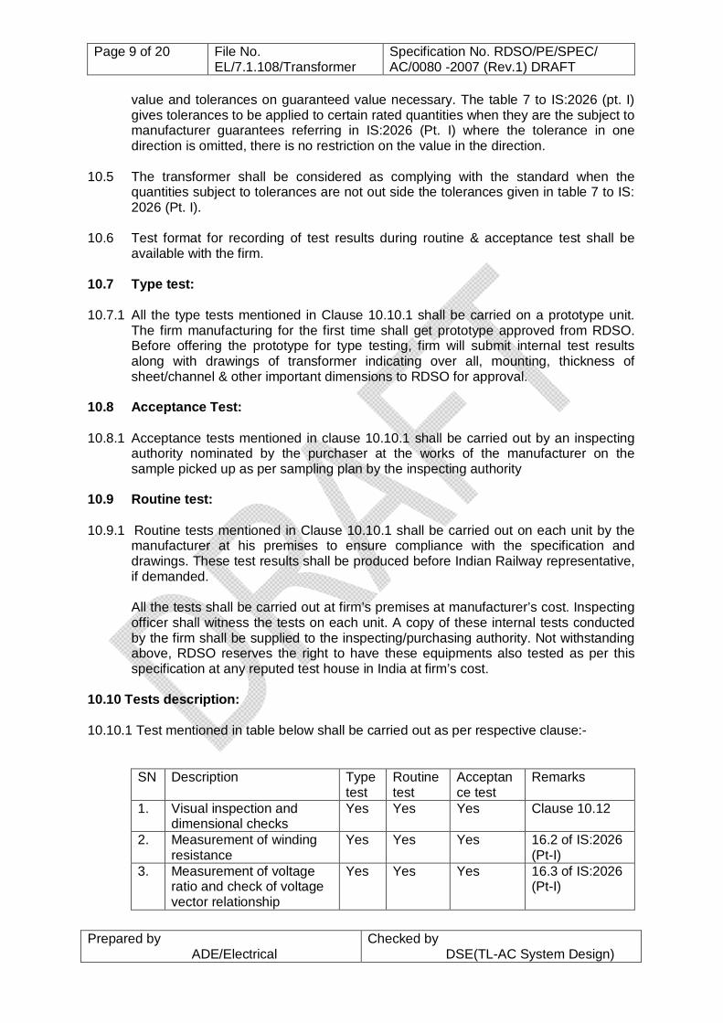
10.10 Tests description: 10.10.1 Test mentioned in table below shall be carried out as per respective clause:-
SN Description Type test
Routine test
Acceptance test
Remarks
1. Visual inspection and dimensional checks
Yes Yes Yes Clause 10.12
2. Measurement of winding resistance
Yes Yes Yes 16.2 of IS:2026 (Pt-I)
3. Measurement of voltage ratio and check of voltage vector relationship
Yes Yes Yes 16.3 of IS:2026 (Pt-I)
Page 10 of 20 File No. EL/7.1.108/Transformer
Specification No. RDSO/PE/SPEC/ AC/0080 -2007 (Rev.1) DRAFT
Prepared by ADE/Electrical
Checked by DSE(TL-AC System Design)
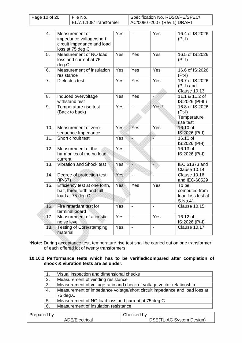
4. Measurement of impedance voltage/short circuit impedance and load loss at 75 deg.C
Yes - Yes 16.4 of IS:2026 (Pt-I)
5. Measurement of NO load loss and current at 75 deg.C
Yes Yes Yes 16.5 of IS:2026 (Pt-I)
6. Measurement of insulation resistance
Yes Yes Yes 16.6 of IS:2026 (Pt-I)
7. Dielectric test Yes Yes Yes 16.7 of IS:2026 (Pt-I) and Clause 10.13
8. Induced overvoltage withstand test
Yes Yes - 11.1 & 11.2 of IS:2026 (Pt-III)
9. Temperature rise test (Back to back)
Yes - Yes * 16.8 of IS:2026 (Pt-I) Temperature rise test
10. Measurement of zero-sequence Impedance
Yes Yes Yes 16.10 of IS:2026 (Pt-I)
11. Short circuit test Yes - - 16.11 of IS:2026 (Pt-I)
12. Measurement of the harmonics of the no load current
Yes - - 16.13 of IS:2026 (Pt-I)
13. Vibration and Shock test Yes - - IEC 61373 and Clause 10.14
14. Degree of protection test (IP-67)
Yes - - Clause 10.16 and IEC-60529
15. Efficiency test at one forth, half, three forth and full load at 75 deg.C
Yes Yes Yes To be computed from load loss test at S.No.4”.
16. Fire retardant test for terminal board
Yes - - Clause 10.15
17. Measurement of acoustic noise level
Yes - Yes 16.12 of IS:2026 (Pt-I)
18. Testing of Core/stamping material
Yes - - Clause 10.17
*Note: During acceptance test, temperature rise test shall be carried out on one transformer
of each offered lot of twenty transformers. 10.10.2 Performance tests which has to be verified/compared after completion of
shock & vibration tests are as under: 1. Visual inspection and dimensional checks 2. Measurement of winding resistance 3. Measurement of voltage ratio and check of voltage vector relationship 4. Measurement of impedance voltage/short circuit impedance and load loss at
75 deg.C 5. Measurement of NO load loss and current at 75 deg.C 6. Measurement of insulation resistance

Page 11 of 20 File No. EL/7.1.108/Transformer
Specification No. RDSO/PE/SPEC/ AC/0080 -2007 (Rev.1) DRAFT
Prepared by ADE/Electrical
Checked by DSE(TL-AC System Design)
7 Measurement of acoustic noise level These tests shall be witnessed by RDSO representative at firm’s premises or can be conducted in NABL accredited laboratory.
10.11 Commissioning tests:
10.11.1The supplier will associate during commissioning of their initial few transformers. 10.12 Visual Examination Test: 10.12.1Overall dimensions and mounting arrangements shall be verified as per the
approved drawings. The dimensions of assemblies and sub-assemblies and constructional detail shall be checked to ensure that these are consistent with sound engineering practices. In addition to the above, the following shall also be verified during the test:
1. Terminal arrangement as per approved drawings. 2. Provision of metric fasteners & its tighteness 3. Marking and danger notice plate 4. Weight verification only one in each sample lot 5. Size and type of crimping sockets 6. Earthing terminals and 7. Lifting arrangement 8. Bill of material etc. as per approved RDSO design document.
10.13 Dielectric test The dielectric tests shall be conducted on transformer completely assembled as in
service, at ambient temperature. Each winding of the transformer shall be subjected to a high voltage value of 5KV (RMS) at 50 Hz for one minute. This test shall be conducted after the temperature rise test
10.14 Vibration & Shock tests
Vibration & Shock tests shall be got carried out by the manufacturer from NABL approved recognized laboratory as per IEC 61373 under the category 1 class B, Location D as given in figure C.1 to above IEC. Test severity and frequency range for functional random vibration tests shall be as per clause 8.1 of above IEC; however the frequency range from 5 Hz to 70 Hz may be accepted till the facilities for frequency range from 5 Hz to 150 Hz at NABL accredited lab is developed. Transformers shall be kept in energized conditions at no load during the test. Table 1, 2 &3 and figure 2 &6 of IEC-61373 shall be followed for the test conditions. After completion of the test, the performance test as given in clause 10.10.2 to this specification shall be repeated. The value of the test results should fall within the tolerance limit specified in IS: 2026 (Pt-I) when compared with the test results carried out before shock & vibration tests.
Page 12 of 20 File No. EL/7.1.108/Transformer
Specification No. RDSO/PE/SPEC/ AC/0080 -2007 (Rev.1) DRAFT
Prepared by ADE/Electrical
Checked by DSE(TL-AC System Design)
10.15 Fire retardant test for terminal board. 10.15.1 A test piece of terminal board of transformer measuring about 150 x 25 mm cut
from terminal board sheet shall be subjected to the luminous flame, preferably supplied by a Bunsen burner. The specimen shall be held with the flat side up at an angle of 45 deg. to the horizontal as shown in Fig.1. The flame shall be of 25 mm in width across the tips.
10.15.2 The flame shall be applied to the specimen at the lower end for 30 seconds and
removed for 30 seconds and then applied again to the same end for the second period of 30 seconds and then removed again. This test shall be carried out with the decorative surface facing up-ward and also the decorative surface facing down-words.
10.15.3 If the test specimen gets ignited, it shall not continue to burn for more than 50
seconds after the flame has been finally removed. 10.16 Water immersion test 10.16.1 The water immersion test shall be done by closing cable entry holes provided on the
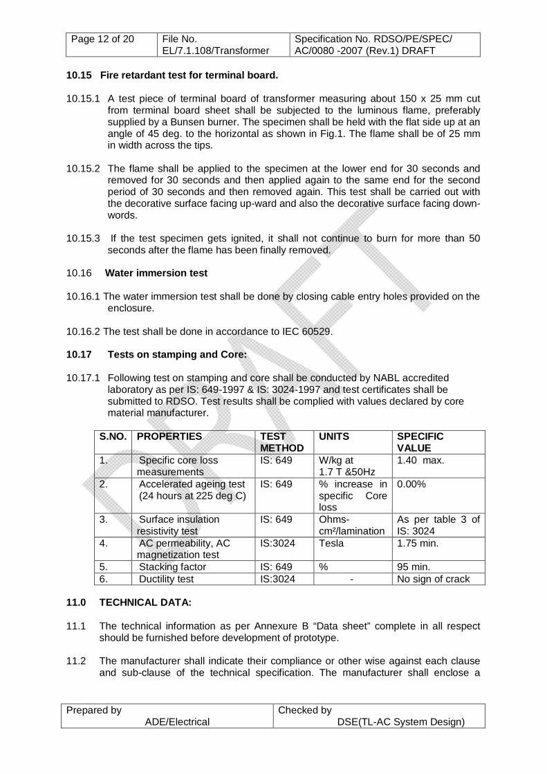
enclosure. 10.16.2 The test shall be done in accordance to IEC 60529. 10.17 Tests on stamping and Core: 10.17.1 Following test on stamping and core shall be conducted by NABL accredited
laboratory as per IS: 649-1997 & IS: 3024-1997 and test certificates shall be submitted to RDSO. Test results shall be complied with values declared by core material manufacturer.
S.NO. PROPERTIES TEST
METHOD UNITS
SPECIFIC VALUE
1. Specific core loss measurements
IS: 649 W/kg at 1.7 T &50Hz
1.40 max.
2. Accelerated ageing test (24 hours at 225 deg C)
IS: 649 % increase in specific Core loss
0.00%
3. Surface insulation resistivity test
IS: 649 Ohms-cm²/lamination
As per table 3 of IS: 3024
4. AC permeability, AC magnetization test
IS:3024 Tesla 1.75 min.
5. Stacking factor IS: 649 % 95 min. 6. Ductility test IS:3024 - No sign of crack
11.0 TECHNICAL DATA: 11.1 The technical information as per Annexure B “Data sheet” complete in all respect
should be furnished before development of prototype. 11.2 The manufacturer shall indicate their compliance or other wise against each clause
and sub-clause of the technical specification. The manufacturer shall enclose a
Page 13 of 20 File No. EL/7.1.108/Transformer
Specification No. RDSO/PE/SPEC/ AC/0080 -2007 (Rev.1) DRAFT
Prepared by ADE/Electrical
Checked by DSE(TL-AC System Design)
separate statement for this purpose, if necessary, indicating the Annexure and clause reference and compliance or otherwise.
11.3 The manufacturer shall submit complete design details along with necessary
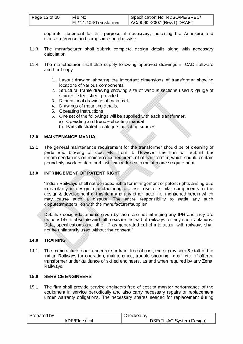
calculation. 11.4 The manufacturer shall also supply following approved drawings in CAD software
and hard copy:
1. Layout drawing showing the important dimensions of transformer showing locations of various components.
2. Structural frame drawing showing size of various sections used & gauge of stainless steel sheet provided.
3. Dimensional drawings of each part. 4. Drawings of mounting details. 5. Operating Instructions 6. One set of the followings will be supplied with each transformer.
a) Operating and trouble shooting manual b) Parts illustrated catalogue-indicating sources.
12.0 MAINTENANCE MANUAL 12.1 The general maintenance requirement for the transformer should be of cleaning of
parts and blowing of dust etc. from it. However the firm will submit the recommendations on maintenance requirement of transformer, which should contain periodicity, work content and justification for each maintenance requirement.
13.0 INFRINGEMENT OF PATENT RIGHT
“Indian Railways shall not be responsible for infringement of patent rights arising due to similarity in design, manufacturing process, use of similar components in the design & development of this item and any other factor not mentioned herein which may cause such a dispute. The entire responsibility to settle any such disputes/matters lies with the manufacturer/supplier. Details / design/documents given by them are not infringing any IPR and they are responsible in absolute and full measure instead of railways for any such violations. Data, specifications and other IP as generated out of interaction with railways shall not be unilaterally used without the consent.”
14.0 TRAINING 14.1 The manufacturer shall undertake to train, free of cost, the supervisors & staff of the
Indian Railways for operation, maintenance, trouble shooting, repair etc. of offered transformer under guidance of skilled engineers, as and when required by any Zonal Railways.
15.0 SERVICE ENGINEERS
15.1 The firm shall provide service engineers free of cost to monitor performance of the
equipment in service periodically and also carry necessary repairs or replacement under warranty obligations. The necessary spares needed for replacement during
Page 14 of 20 File No. EL/7.1.108/Transformer
Specification No. RDSO/PE/SPEC/ AC/0080 -2007 (Rev.1) DRAFT
Prepared by ADE/Electrical
Checked by DSE(TL-AC System Design)
service should be available with the service engineers at all possible places where these coaches are maintained.
16.0 CARTEL FORMATION 16.1 The firms shall submit a declaration in this regard as per enclosed annexure C. 17.0 ENCLOSURE
i) The over all dimensions, construction and
mounting of the transformer RCF Drawing No. CC71216 with latest alteration
ii) Terminal board for 60 KVA transformer
RCF drawing No.CC71217 with latest alteration
iii) Fire retardant test
Figure 1
iv) Bill of Material
Annexure - A
v) Data sheet
Annexure - B
vi) Declaration against cartel formation
Annexure – C

Page 15 of 20 File No. EL/7.1.108/Transformer
Specification No. RDSO/PE/SPEC/ AC/0080 -2007 (Rev.1) DRAFT
Prepared by ADE/Electrical
Checked by DSE(TL-AC System Design)
ANNEXURE – A to Specification No. RDSO/PE/SPEC/AC/ 0080 - 2007 (Rev.1)
ACCEPTABLE MAKE AND SPECIFICATION OF THE MATERIAL USED IN 60 KVA TRANSFORMER
S.No Description of the
material Nos. Make Specification
1. Anti vibration mountings (loose supply)
4 Resistoflex / Dunlop/ Mettalisitc or any other make with prior approval of RDSO
-
2. Super enameled copper round/rectangular winding wire
As required
As per latest vendor list of RDSO available at web site www.rdso.gov.in
IS: 13730, Pt 13 -93/ IS: 13730, Pt 29
3. Connecting lead As required
As per latest vendor list of RDSO available at web site www.rdso.gov.in
IS: 6195
4. Epoxy resin As required
FT 2005/500EK Dr BECK
5. Grommet/PG coupler
10 PMA or any other make with prior approval of RDSO
6. CRGO grade M27 As required
M/s POSCO(Korea), M/s NIPPON STEEL Corporation (Japan), M/s THYSSCENKRUUP(INDIA) or any other make with prior approval of RDSO.
IS: 3024 of 0.27 mm thickness
7. SRBGF material Make to be submitted by the firm at the time of design approval.
IS:10192-1982 with EP3 grade
8. Enclosure 01 - SS 304, 2.0 mm thick
9. Terminal Board 01 Any make approved by RDSO
As per clause No. 8.10
10. Crimping socket/lug
As required
Dowells or any other make approved by RDSO
Note: 1. All the materials should have fire retardant property. 2. Firm should have test records of all raw material used in their transformer.
3. Firm will submit the purchase bills of raw materials from approved sources as above.
Page 16 of 20 File No. EL/7.1.108/Transformer
Specification No. RDSO/PE/SPEC/ AC/0080 -2007 (Rev.1) DRAFT
Prepared by ADE/Electrical
Checked by DSE(TL-AC System Design)
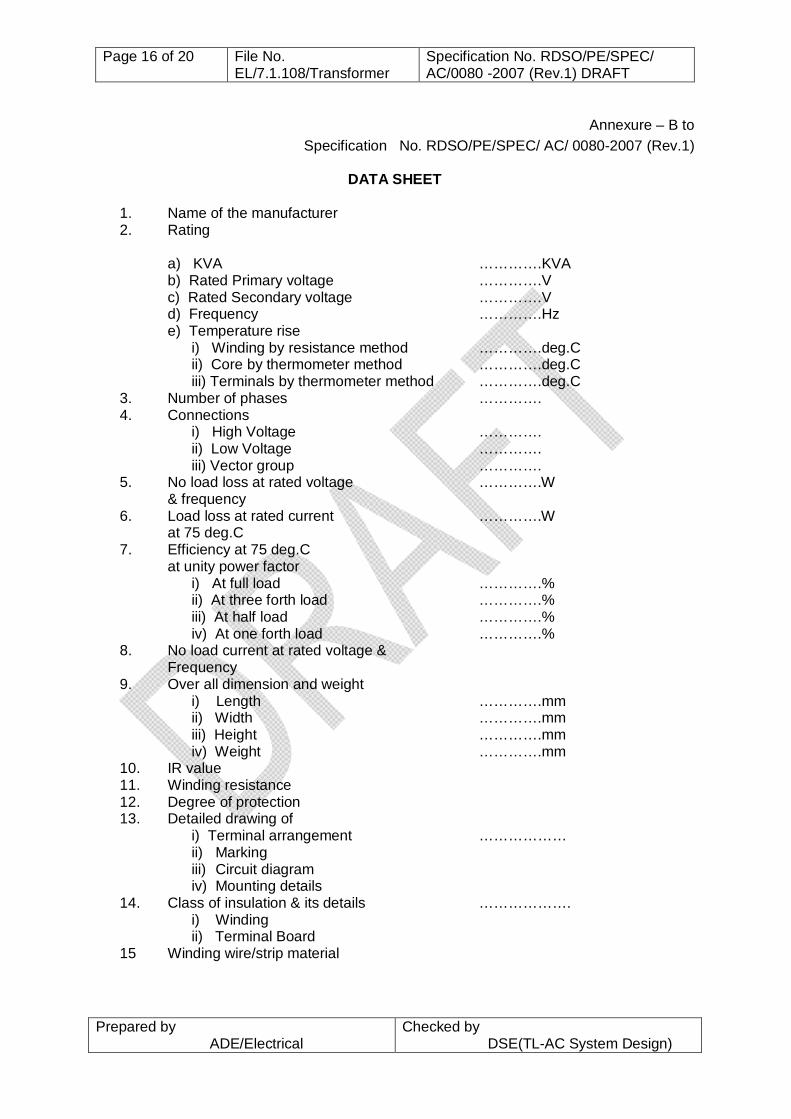
Annexure – B to Specification No. RDSO/PE/SPEC/ AC/ 0080-2007 (Rev.1)
DATA SHEET
1. Name of the manufacturer 2. Rating
a) KVA ………….KVA b) Rated Primary voltage ………….V c) Rated Secondary voltage ………….V d) Frequency ………….Hz e) Temperature rise i) Winding by resistance method ………….deg.C ii) Core by thermometer method ………….deg.C iii) Terminals by thermometer method ………….deg.C
3. Number of phases …………. 4. Connections i) High Voltage …………. ii) Low Voltage …………. iii) Vector group …………. 5. No load loss at rated voltage ………….W & frequency 6. Load loss at rated current ………….W at 75 deg.C 7. Efficiency at 75 deg.C at unity power factor i) At full load ………….% ii) At three forth load ………….% iii) At half load ………….% iv) At one forth load ………….% 8. No load current at rated voltage &
Frequency 9. Over all dimension and weight i) Length ………….mm ii) Width ………….mm iii) Height ………….mm iv) Weight ………….mm 10. IR value 11. Winding resistance 12. Degree of protection 13. Detailed drawing of i) Terminal arrangement ………………
ii) Marking iii) Circuit diagram iv) Mounting details
14. Class of insulation & its details ………………. i) Winding ii) Terminal Board
15 Winding wire/strip material
Page 17 of 20 File No. EL/7.1.108/Transformer
Specification No. RDSO/PE/SPEC/ AC/0080 -2007 (Rev.1) DRAFT
Prepared by ADE/Electrical
Checked by DSE(TL-AC System Design)
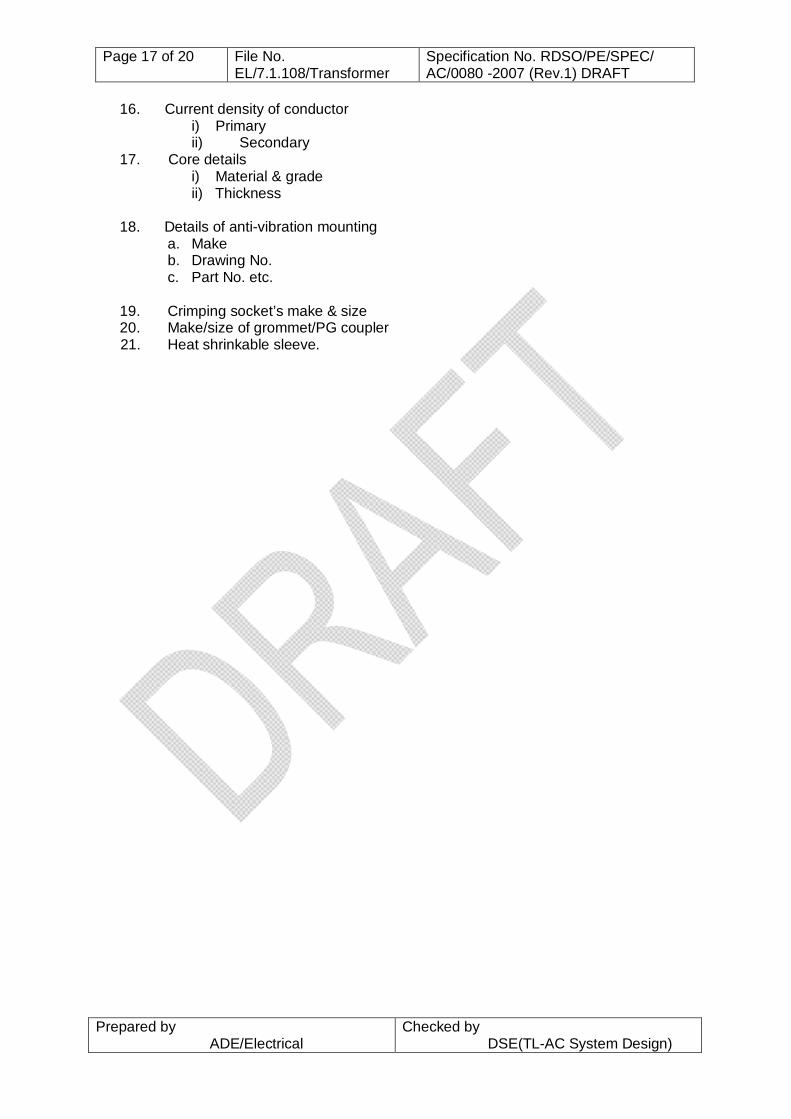
16. Current density of conductor i) Primary ii) Secondary
17. Core details i) Material & grade ii) Thickness
18. Details of anti-vibration mounting
a. Make b. Drawing No. c. Part No. etc.
19. Crimping socket’s make & size 20. Make/size of grommet/PG coupler
21. Heat shrinkable sleeve.

Page 18 of 20 File No. EL/7.1.108/Transformer
Specification No. RDSO/PE/SPEC/ AC/0080 -2007 (Rev.1) DRAFT
Prepared by ADE/Electrical
Checked by DSE(TL-AC System Design)
ANNEXURE – C to Specification No. RDSO/PE/SPEC/AC/ 0080-20007 (Rev.1)
UNDERTAKING AGAINST CARTEL FORMATION
We……………………….. hereby, give an undertaking that as a Registered Vendor
for manufacture and supply of ……………………………., will not be a part of a cartel with
other vendors and will be quoting competitive rates in the tenders invited by the Indian
Railways/PUs.
We …………………………… are aware of the fact that the Registering Authority i.e.
RDSO may de-list the name of our firm from the Master List of Approved Vendors if
complaint is received about such cartel formation from any of the Railways/Production Units.
Seal and signature
(Authorized signatory of the firm)
Date: Place: Seal:

Page 19 of 20 File No. EL/7.1.108/Transformer
Specification No. RDSO/PE/SPEC/ AC/0080 -2007 (Rev.1) DRAFT
Prepared by ADE/Electrical
Checked by DSE(TL-AC System Design)

Page 20 of 20 File No. EL/7.1.108/Transformer
Specification No. RDSO/PE/SPEC/ AC/0080 -2007 (Rev.1) DRAFT
Prepared by ADE/Electrical
Checked by DSE(TL-AC System Design)
DISTRIBUTION CHIEF ELECTRICAL ENGINEER:
1 Northern Railway, Baroda House, New Delhi – 110 001. 2 Central Railway, 2 nd Floor, Parcel office, CST Mumbai – 400 001. 3 Eastern Railway, Fairlie Place, Kolkata – 700 001. 4 South Eastern Railway, Garden Reach, Kolkata – 700 043 5 Southern Railway, Park Town, Chennai – 600 003. 6 Western Railway, Churchgate, Station Building Mumbai – 400 020. 7 South Central Railway, Rail Nilayam, Secunderabad – 500 371. 8 East Central Railway, Dighi Distt- Vaishali, Hajipur Bihar- 844 101. 9 North Central Railway, Subedarganj. Allahabad- 211033.
10 South Western Railway, 1st Floor, DRM Office, Hubli 580 020 11 South East Central Railway, Bilaspur.495004 12 North East Frontier Railway, Maligaon, Guwahati - 781001 13 North Eastern Railway, Gorakhpur – 273001 14 North Western Railway, Jaipur – 302006 15 West Central Railway, Jabalpur - 482001 16 East Coast Railway, Bhuvneshwar, Orrisa – 751016 17 Konkan Railway, Belapur Bhavan, Sector-11, Belapur, Mumbai - 400614 18 Metro Railway, 33 /1 J.L. Nehru road, Kolkata- 700071 19 Integral coach factory, Perambur, Chennai - 600038 20 Rail Coach Factory, Kapurthala (Punjab) – 144 602
CHIEF WORKS MANAGER: 1 Matunga Workshop, Central Railway, Mumbai 400 019. 2 Liluah Workshop, Eastern Railway, Howrah 3 C&W Workshop , Northern Railway, Alambagh, Lucknow-226 05 4 C & W Workshop,N. Rly., Jagdhari – 135 002 5 Mechanical Workshop, NER, Gorakhpur – 273 012 6 Carraige Workshop, Southern Railway, Perambur, Ayanavaram, Chennai – 600023. 7 SCR, Lallagudda Workshop, Lallaguda, Secunderabad - 500017 8 Carriage Workshop, Western Railway, Lower Parel, Mumbai-400013 9 CRWS, W. C. Railway, Nishatpura, Bhopal-462010
10 Carriage Workshop, NW Rly,. Ajmer - 305001 11 Carriage Repair Workshop, Gadag Road, SWR, Hubli – 580 020 12 Carriage Workshop, S.W. Railway, Mysore Vishwanath. 13 Carriage Workshop, SE Rly., Kharagpur - 721301 14 New Bongaigaon , Railway Workshop, Dangtal, Distt. Bongaigaon, Assam-783380 15 Carriage and Wagon Workshop, N. C. Rly., Jhansi – 248003 16 Carriage and Wagon Workshop, WC Rly., Kota - 324002 17 Carriage and Wagon Workshop, Eeastern Rly., Liluha - 711204 18 Carriage and Wagon Workshop, W. Rly., Pratap Nagar, Vadodara - 390004 19 Carriage and Wagon Workshop, N Rly., Amritsar - 143001 20 Central Workshop, Goldenrock, S. Rly., Trichi - 620004
OTHERS: 1 Director, IRIEEN, Nasik Road (Maharashtra). - 422101 2 Senior Professor (Elect.), Railway Staff College, Lalbaug, Vadodara. - 390004 3 Director, IRCAMTECH, Maharajpur, Gwalior – 474 020.