If you have issues viewing or accessing this file contact ... · WILLIAM A. O'NEILL GOVERNOR...
152
u.s. Department of Justice National Institute of Justice 98527 This documenl has been reproduced exaclly as received from Ihe person or organization originating it. Paints of view or opinions staled in this document are Ihose of Ihe authors and do not necessarily represent Ihe official position or policies of the National Institute of Jusllce. Permission to reproduce this copyrighted material has been granted by Cormecticut State Policeh.'prensic Science Laboratory to the National Criminal Justice Reference Service (NCJRS). Further reproduction outside of the NCJRS system requires permis- sion of the copyright owner If you have issues viewing or accessing this file contact us at NCJRS.gov.
Transcript of If you have issues viewing or accessing this file contact ... · WILLIAM A. O'NEILL GOVERNOR...
u.s. Department of Justice National Institute of Justice
98527
This documenl has been reproduced exaclly as received from Ihe person or organization originating it. Paints of view or opinions staled in this document are Ihose of Ihe authors and do not necessarily represent Ihe official position or policies of the National Institute of Jusllce.
Permission to reproduce this copyrighted material has been granted by
Cormecticut State Policeh.'prensic Science Laboratory
to the National Criminal Justice Reference Service (NCJRS).
Further reproduction outside of the NCJRS system requires permission of the copyright owner
If you have issues viewing or accessing this file contact us at NCJRS.gov.
PHYSICAL EVIDE~CE
AND
FORENSIC SCIENCE
Henry C. Lee, Ph. i).
David Faige, M.B.A.
R. E. Gaensslen, Ph.D.
Kathy-Leigh Russo, M.B.A.
Hith the special assistance of:
Captain Michael Bochicchio
Captain Jerome Drugqnis
Hrs. Roxanne D'Aquino Lieut. LaHrence lierrill
FORENSIC SCIENCE LABORATORY
CONNECTICUT STATE POLICE
The printing of this manual Has made possible by the Connecticut Insurance
Placement Facility representing the Connecticut Insurance Industry
1&'5:<7
WILLIAM A. O'NEILL GOVERNOR
October, 1984
STATB OF CONNECfICUT EXECUTIVE CHAMBERS
HARTFORD
The skilled and dedicated members of police and fire departments in communities throughout our State stand ready at all times to safeguard the lives, property, and rights of our citizens.
Our law enforcement officers are aided by the knowledge of every possible technique and resource which enables them to do their jobs successfully.
In criminal investigation, the proper identification, collection, handling, preservation an~ analysis of physical evidence are particularly crucial to precision and accuracy in each investigation.
This comprehensive manual, compiled by the ~'mnecticut State Police, offers helpful guidelines and infc·,: ~ation to police and fire investigators to assist in the performance of their duties. It will certainly add to the tools available to all investigators, helping them considerably to combat crime and make our State a better and safer place in \~hich to live and work.
I am confident that this manual \~ill be a most valuable addition to our already effective arsenal against crime.
~r(l/
"C!./ A.-L - - . O'Neill Governor
Governor William A. O'Neill
Col. Lester ~. Forst Commissioner Department of Public Safety
At a crime sr:ene, every law enforcement officer shares the responsibili~y of preserving and collecting as much pertinent physical evidence as possible. The: objective of this handbook is to make available to police and fire investigators a practical guide for the proper collecting, preserving and nandling of physical evidence.
The value of properly collected and examined physical evidence by the Forensic Science Laboratory cannot be overly emphasized. Forensic science has become a vital part of our criminal justice system. Working as a team, the field investigators and our laboratory personnel present a formidable arsenal in Connecticut's war against crime.
It is hoped that the handbook will promote the utilization of physical evidence in criminal investigations and encourage the law enforcement officer to make use of the services available at the Connecticut State Police Forensic Science Laboratory.
~/~ Colonel LCQter J. Fors~
COMMISSIONER OF PUBLIC SAFETY
Lt. Col. John A. Mulligan Executive Officer Connecticut State Police
For more than 80 years, the State Police have boon il)volved in
the prevention, investigation, Rnd solution of crime in the State. In more recent times, scientific criminal investigation and forensic
science have come to play a much greater rolo in the effort to control
crime. The Department has been in the forefront of this trend, and
has developed an outstanding full-service Forensic Science Laboratory.
But .:he Laboratory cannot do the job alone. The proper recognition,
collection, preservation, and analysis of physical evidence d~rected tOl<ard the solution of cases requires a team effort--investJ.gators,
crime scene personnel, and laboratory examiners working together with a common goal.
The Department realizes the importance of cooperation and
communication between scene personnel, patrol officers and laboratory
examiners. We are proud of the accumplishments of our State Police
Forensic Lab but we know that continued success is totally dependent
on a high degree of cooperation and interaction bet\~een investigators
and examiners. This book is designed to assist officers in under
standing the processes involved in physical evidence processing and
analysis, and thus to foster cooperation between officers and the
Laboratory. It will also help investigators in understanding the
types of analysis that can be done, the types of results that can
be obtained, and should be helpful in formulating requests for
eVidence analysis. We are pleased to make this book available to
police officers throughout the State.
(Ju,~ Li~ Colo el John Mulligan EXECUTIVE OFFICER CONNECTICUT STATE POLICE

ACKNOWLEDGEMENTS
It is a pleasure to express our thanks to the following:
Captain Michael B"chicchio, Captain Jerome Drugonis,
Major Wilfred Blanchette, Najar John Taylor, Najar Donald Nurse,
and Lt. Col. James Rice.
We a1.,,) wish to thank our colleagues:
Deborah Baughn, James Behrendt, Leo Blanchette, William Duune,
Robert Finkle, David Gibbs, Hary Beth Cuman, Anthony Gura,
Robert Hathaway, Kevin Heche, Louis Kapitulik, Diana Kirchhoff,
Anthony Liberi, Tina LoBello, Ronald Luneau, Thomas HcNullen,
Robert Hills, Beryl Novitch, Thomas O'Brien, Eugene Ozerhoski,
Elaine Pagliaro, Harshall Robinson, Fred Ruszala, Harius Venclauskas,
Theodore Yarusewicz, and Stanley Zaniewski; and especially our thanks
to Paul Hebert for his help with the illustrations, and to
Roxanne D'Aquino, Patricia Giannini, Enza Bombaci, and Doreen Freeman
for their help with the text.
We would also like to express our appreciation to Commissioner
Lester J. Forst and Lt. Col. John A. Hulligan for their support and
encouragement in this project, and to the members of the Connecticut
State Police for their interest and support.
We extend our thanks to police and fire departments in Connecticut
and all other State and local law enforcement agencies for their help
in identifying the need for, and their assistance in, this pr<Jject.
A special thank-you to the Connecticut Insurance Placement Facility
representing the Cunnecticut Insurance Industry for their assistance
in this project, making it available to the law enforcement community.
iii
Henry C. Lee, Ph.D.
David Paige, M.B.A.
R. E. Gaensslen, Ph.D.
Kathy-Leigh Russo, H.B.A.

INTRODUCTION
In recent years, the criminal justice agencies have become increasingly aware of the value of physical evidence as mandates of the Supreme Court dealing with the rights of individuals have imposed greater restrictions on methods of investigation. Investigators have dealt with this problem by learning to exploit the merits of forensic science.
The work of the forensic scientists is not for the benefit of either the prosecution or defense j,n our judicial proceedings. Thej.r function is to use all the scientifi~ skill and knowledge available to find out the tr~th. To this end, injustice shall not be done to any member of our society.
This manual is intended as a simplified introduction to the fundamentals of forensic science and scientific evidence, but not as an in-depth treatment of the subject. It should serve the law enforcement officer as a primer, the experienced criminologist as a refresher, and the general reader as a thought-provoking introduction to the field of forensic science.
PART ONE is devoted to the importance of physical evidence &nd the basic principles of forensic science.
PART TWO deals with the collection of physical evidence and methods of crime scene search.
PART THREE covers the submission of evidence to the Laboratory for examination.
PART FOUR discusses the individual types of physical evidence and how they are examined in the Laboratory.
iv

TABLE OF CONTENTS
Pat:t 1 - J:'hysical Evidence 1
Areas of Specialization
Criml.nalis tics 1
Questioned Document Examination 3
Forensic Chemistry 3
Trace Analysis 3
Firearms Examination 3
Latent Fingerprints 4
Voice Analyois 4
Serology 4
Part II - Crime Scene Search and Collection of PhYSical Eviden-::e 6
Sequence of Operations:
Scene Preservation 6
Scene Observation 6
Photography 7
Sketch Haps 9
Physical Evidence 11
Fingerprints 15
Impressions and Imprints 17
Hair 30
Fibers 32
Debris - Soil 32
Glass 33
Paint 33
Tool Harks 34
Firearms 35
v
Part J.II -
Pllrt IV -
Obliterated Serial Numbers
Body Fluid!)
Accelerants
Documents
Voice Identification
Evidence Submission to the Laboratory
Laboratory Examination of Physical Evidence
Accelerants
Blood
Body Fluids
Documents
Explosives
Fingerpdnts
Firearms Evidence
Tool Harks
Gunshot Residue
Hairs
Imprint and Impression Evidence
Pattern Evidence
Bloodstain Patterns
Glass Fracture Patterns
Photography Section
Reconstruction
Trace Evidence
vi
36
36
46
46
54
56
63
63
66
73
76
85
87
98
104
109
112
115
118
118
121
125
128
132

Table 1
Table 2
Table 3
Table 4
Table 5
Table 6
Table 7
Table 8
Table 9
TABLES
- Types of Evidence Used for Analysis 2
- Categories for Identification and Individualization 5
- Expos'Jre G')ide for 120 Cameras Using Tri-X (ASA 400) Film 10
- Collection of Blood Stains at Crime Scene
- Collection of Whole Blood at Crime Scene
- Field Investigation Kit
~ Where to Find Handl~riting Samples
- Pbysical Evidence Packaging Chart
- Blood-Group Systems
40
41
43
49
60
68
Table 10 - Red-Cell Isoenzyme Systems 69
Table 11 - Serum Group Systems 70
Table 12 - The Present Approaches to the Individualization of Blood Stains 72
Table 13 - Color Test Reagents and Reactions for Explosives 86
Table 14 - Methods of Visualizing Latent Fingerprints 95
Table 15 - Fingerprint Classification 97
Table 16 - Shot Comparison Table 102
Table 17 - Measurements or Properties of Lead Balls Just Fitting Bore
Table 18 - Analysis Factors in the Comparison of Hair
vii
103
116

Figure 1
Figure 2
Figure 3
Figure 4
Figure 5
Figure 6
Figure 7
Figure 8
Figure 9
Figure 10
Figure 11
Figure 12
Figure 13
Figure 14
Figure 15
Figure 16
Figure 17
Figure 18
Figure 19
Figure 20
Figure 21
Figure 22
Figure 23
Figure 24
Figure 25
Figure 26
Figure 27
FIGURES
- Rough Sketch of Homicide Crime Scene
- Finished Sketch of Homicide Cdme Scene
- Common Search Patterns for Crime Scenes
- Overall View Showing Shoepdnt
- Photographing of Shoeprint
- Photograph of Shoeprint
- Hardening of Shoeprint Prior to Casting
- Physical Barrier Placed Around Shoeprint
- ~lixing of plaster of Pads
- Plaster of Paris Poured Into Hold
- Reinforcement of Cast
- Completion of Pouring
- Harking of Cast
- The Druggist Fold
- Ground-Off Serial Number on Firearm
- Obliterated Serial Number on Firearm Now Visible
- The Gas Chromatograph
- Request Form for Examination of Physical Evidence
- Suggested Format for an Evidence Tag
- Chromatograms
- PGH Patterns with Isoelectric Focusing
- Hicroscopic Vie,~ of Spermatozoa
- Microscopic View of Rhombic Crystals (Choline)
- Comparison Chart for Handwriting
- Jai-Alai Ticket Alterations Hade Visible
- Altered Check
- Alterations on Check Hade Visible
viii
12
13
14
20
21
22
23
24
25
26
27
28
29
31
37
38
47
57
59
65
71
74
75
78
79
80
81
Figure 28
Figure 29
Figure 30
Figure 31
Figure 32
Figure 33
Figure 34
Figure 35
Figure 36
Figure 37
Figure 38
Figure 39
Figure 40
Figure 41
Figure 42
Figure 43
Figure 44
Figure 45
Figure 46
Figure 47
Figure 48
Figure 49
Figure 50
- Alterations on Check Made Visible
- Indented Writing ~Iade Visible
- Legibility of Burned or Charred Docume:11ts
- Gas Chromatograms of Gasoline
- Fingerprint Patterns
- Fingerprint Patterns
- Secretions of Sweat G:ands of the Fingers
- Fingerprint Comparison Charts
- Cutaway View of Cartridges
- Schematic Analysis of Firearms IdentiHcation
- Match Between Breech Face Markings on Shells
- Positive Hatch Between Bullets
Door Frame Striker Plate and Screwdriver
- Tool Hark Comparison
- Gunshot Residue
- Cutaway View of a Human Hair
- Parts of the Human Hair
- Diameter of Blood Stain Used to Estiulate Height of Drop
- Shape of Blood Stain Used to Estimate Angle of Drop
- Glass Fractures
- Glass Fractures
- Translucent Object Lit from Front
- Translucent Object Lit from Behind
Figure 51 - Handkerchief Under Normal Light
Figure 52 - Laundry Mark on Handkerchief Made Visible
Figure 53
Figure 54
Figure 55
- Comparison bf Flat Lighting vs. Side Lighting
- The Micro-UV-visible Spectrophotometer (NANOSPEC/lO)
- Scanning Electron Micrograph
ix
82
83
84
88
89
90
92
96
100
101
105
106
107
108
III
113
114
119
120
123
124
126
127
129
130
131
134
136
EART ONE
PHYSICAL EVIDENCE AND FORENSIC SCIENCE

1. PHYSICAL EVIDENCE
Physical evidence serves to associate the cr:l.minal with a particular crime. For ~xample: a latent fingerprint found at a crime scene is subsequently identified by matching it with a known fingerprint; or a blood stain is later identified as being similar in genet1c markers to those of a particular individual. While physical evidence may be used for reconstruction of the crime scene, it can also be used to prove the innocence of an individual as well.
Virtually any type of material can become physical evidence. It may be as small as a dust particle or as large as a train. Table 1 lists Gome thirty categories of the types of evidence frequently analyzed by forensic science laboratories. These listings can be dIvided into four groups: biological, chemical, physical (impression), and miscellaneous.
When one considers tbe various types of eviden~e mentioned in Table I, it becomes obvious that there are available to the forensic scientist many different methods of discovering the truth. .
A. Areas of Specialization
In recent years, the forensic science field has grown tremendously, causing considerable expansion in forensic laboratories in both size and operations~ The application of forensic science in criminal and civil investigation has rapidly diversified since physical evidence occurs in many varieties. Because a rather different expertise is required for examining each piece of physical evidence, the forensic science profession, like thrt of medicine, has shifted from general practice toward specialization. The following is a partial list of areas of specialization.
1. Criminalistics
Criminal is tics may be defined as a knowledge of the collection, identification, individuali7ation, and evaluation of physical evidence. A criminalist is a generalist by necessity, drawing upon a wide spectrum of scientific knowledge to help the investigator in the recognition and recovery of a variety of trace evidence. He also helps detectives to develop investigative leads and assists the courts in the interpretation and evaluation of findings. A major objective, aside from identification of evidence, is to individualize evidence to the maximum possible extent while attempting to
1

TABLE I
TYPES OF EVIDENCE USED FOR ANALYSIS
Biological
Blood Semen Saliva Other Body Fluids Hair Botanical Pathological
Physical (.:mpression)
Fing,erprin ts Fir .. ,arms Hand~riting
Indented Writing Number Restoration Footprints and Tire Marks Tool Marks Typewriting
,2
Chemical -----Fibers Chemicals Glass Soil Gun Powder Metallurgical Mineralogical Narcotics Paper Pharmacological Toxicological
Miscellaneous
Laundry Marks Voiceprint Polygraphy Photographic

determine its precise, unique origin. The philosophy of individualization is unique to forensic science and has made it different from any other science.
2. Questioned Document Examination
The questioned document examiner is involved in the scientific examination of handv7riting, typewriting, printing, ink, and paper as well as many other aspects of a document or written instrument. Examinations can involve: Identifying the source or writer of a document, determining if a signature is authentic or a for.gery, determining the age of the document, deciphering obliterated or erased writing, detecting alterations, and examining indented writing and burned or charred documents.
3. Forensic Chemistry
Forensic chemistry involves the identification and analysis of drugs, toxic substances, accelerants, gunshot powder residue, explosives, and other chemical substances. Qualitative and quantitative methods are utilized to identify unknown substances and to make comparisons between known and unknown materials. It is also the function of the forensic chemist to attempt to trace unknown substances to a specific origin.
4. Trace Analysis
The trace analyst combines the methodology of micro-scopy, instrumental and chemical techniques in examination of hair, fibers, glass, soil, plant material, mineral, and air borne particles. While it is difficult to make absolute individualizations in these areas, th~ trace analyst can make identifications with a high degree of probability of individuality.
5. Firearms Examination
The examination of firearms, discharged bullets, cartridge cases, shotgun shells, ammunition, and various weapons are all conducted by a firearms examiner. Generally, a fire-arms examiner has to answer three questions: (1) What kind of weapon fired the bullE't? (2) Did this particular weapon fire this bullet or cartridge case? (3) \~at kind of ammunition was used? In addition to answering these questions, the firea~~s examiner studies garments and other objects to
3

detect firearms discharge residue and to determine the distance from which a weapon was fired. Many firearms examiners also perform tool mark comparisons. With increasing frequency, tools of many kinds are used as weapons or in the perpetration of crimes. Whenever a teol has been used to move an object, there is a good chance that the tool can be identified with reasonable certaint: .
6. Latent Fingerprints
Latent fingerprint examiners are responsible for processing '.atent fingerprints on evidence stJbm;ttted to a forensic :<,ab<;Jratory from crime scenes. There are many chemical and rhysical methods for the detection and visualization of '.atent fingerprints. After the latent f:Lngerpdnts have been developed, the examiner also has to compare the latent print mth the suspect's inked prints to determine whether or no~ they match.
7. Voice Analysis
In cases involving tape recorded messages containing threats, false alarms, bomb threats, or other criminal violations, it may be necessary to employ the skill of the voiceprint examiner to tie the unknown voice to a particular suspect. A sound spectrograph is used to transform speech into a visual graphic display. The validity of this technique as a means of personal identification rests on the premise that the sound patterns produced in speech are unique to the individual and that the spectrogram or voiceprint displays this uniqueness.
8. Serology
Forensic serologists apply the principles and techniques of biochemistry, serology, immunology, hematology, and chemistry to the identification and individualization of blood and other body fluids. The questions which are generally answered by the examination are as follows: (1) What type of stain is it? (2) What species does the stain belong to? (3) Does the questioned stain have the same blood groups and isoenzyme patterns as a certain known sample? Hajor crimes such as homicide, rape, and physical aRsault generally involve blood as evi6ence.
4
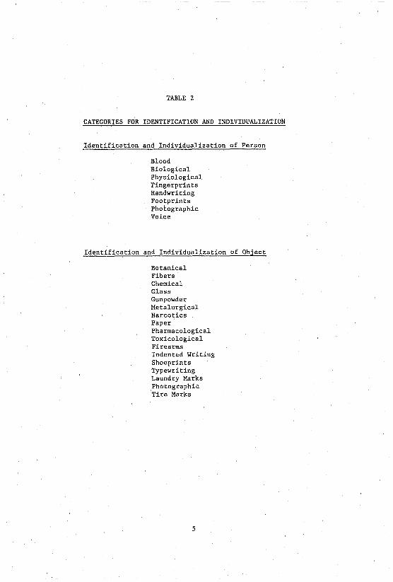
TABLE 2
CATEGORIES FOR IDENTIFICATION AND INDIVIDUALIZATION
Identification and Individualization of Person
Blood Biological Physiological Fingerprints Handwriting Footprints Photographic Voice
Identification and Individualization of Object
Botanical Fibers Chemical Glass Gunpowder Metalurgical Narcotics Paper Pharmacological Toxicological Firearms Indent~d Writing Shoeprints Typewriting Laundry Marks Photographic Tire Marks
5

CRIME SCENE SEARCH
AND
COLLECTION OF PHYSICAL EVIDENCE

II. CRIME SCENE SEARCH AND COLLECTION OF PHYSICAL EVIDENCE
Generalist Concept: to properly process a crime scene for physical evidence, it is necessary to view the whole scene in its entirety and not just from the perspective of the singular operations involved in the processing, Le., fingerprints. blood, photography, .'iltc.
SEQUENCE OF OPERATIONS
A. Scene Preservation
1. Secure th~ scene. (This applies to crimes where first aid is not necessary - if it is necessary, it should be the first concern.)
2. Restrict entrance to scene.
a. Includes officers and other investigators as well as members of news media. Anyone entering the scene should be prepared to offer court testimony as to their reason.
3. Notify Agencies.
a, Notify the appropriate Field District Commander av~ its Major Crime Squad.
b. Notify the State "olice Forensic Science Laboratory.
c. Notify the prosecutor's office, the medical examiner and any specialist that may be required.
B. Scene Observation (Crime Scene Team Leader)
1. Menl'ally reconstruct what has happened as it will yield probable sources of evidence.
2. Begin notes. These should include; date, time, weather, who is present, lights on or off, doors locked or open, air conditioner on or off, etc. Tha notes should answer the questions - who, what, where, when, why, and how? If a tape recorder is available, it is strongly recommended that it be utilized at this time.
3. Assign specific responsibilities to crew members, e.g., evidence collector, photographer, fingerprint processing, etc.
6
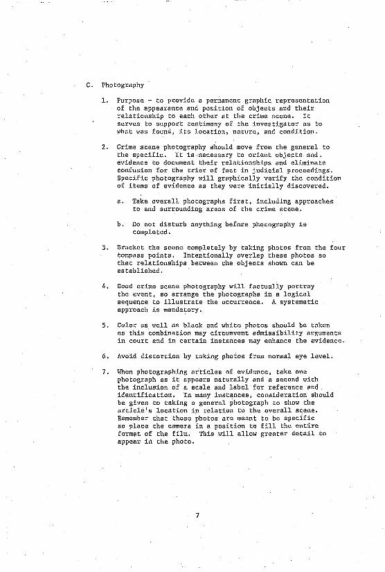
C. Photography
1. Purpose - to provide a permanent graphic representation of the appearance and position of obj ects and their relationship to each other at the crime scene. It serves to support testimony of the investigator as to what was found, its location, nature, and condition.
2. Crime scene photography >lhould move from the general to the specific. It is necessary to orient objects and. evidence to document their relationships and eliminate confusion for the trier of fact in judicial proceedings. Specific photography will graphically verify the condition of items of evidence as they were initially discovered.
a. Take overall photographs first, including approaches to and surrounding areas of the crime scene.
b. Do not disturb anything before photography is completed.
3. Bracket the scene completely by taking photos from the four compass points. Intentionally overlap these photos so that relationships between the objects shown can be established.
4. Good crime scene photography will factually portray the event, so arrange the photographs in a logical sequence to illustrate the occurrence. A systematic approach is mandatory.
5. Color as well as black and white photos should be taken as this combination may circumvent admissibility arguments in court and in certain instances may enhance the evidence.
6. Avoid distortion by taking photos from normal eye level.
7. When photographing articles of evidence. take one photograph as it appears naturally and a second with the inclusion of a scale and label for reference and identification. In many instances. consideration should be given to taking a general photograph to show the article's location in relation to the overall scene. Remember that these photos are meant to be specific so place the camera in a position to fill the entire format of the film. This will allow greater detail to appear in the photo.
7

8. Consider taking aerial photographs in major crimes to orient the crime scene to the surrounding area geographically.
9. Choose a camer~ that will have the largest film format av.ailable and still be convenient for handling at crime scenes. A larger format will allow enlargment of photographs with the least amount of loss of clarity caused by grain in the finished photographs.
a. Additional consideration should also be given to the use of available cameras for color slides. These slides can be of invaluable assistance in court testimony as visual aids, thereby enhancing oral testimony.
10. A sketch should be made by the photographer showing the various photo numbers regarding camera locations and angles. It is not necessary to make this a scale drawing but the fact that it is not to scale should be noted on the drawing.
11. Light Meters - the addition of an incident type light meter (measure~ light falling on an object) to camera equipment will result in better crime scene and evidence photography. This equipment takes the guess work out of exposure saving both time and resources.
12. Tripods should be used in the following situations:
a. When shooting with an exposure time greater than 1/30 second.
b. For ground glass focusing or special evidence photography, e.g., footprints, tire tracks, etc.
c. Difficult angle or camera position.
13. Illumination techniques - the crime scene photographer should be familiar with the following methods of lighting to maximize or enhance articles of evidence:
a. Flat lighting - consisting of two light sources placed approximately 45° to the target at the same height as the camera lens. The result is that shadows will be eliminated.
8
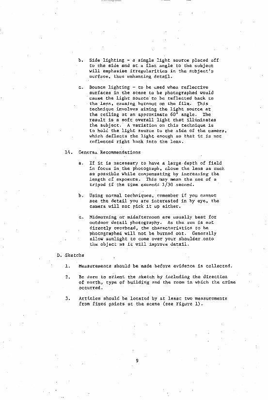
b. Side lighting - a single light source placed off to the side and at a flat angle to the subject will emphasize irregularities in the subject's surface. thus enhancing detail.
c. Bounce lighting - to be used when reflective surfaces in the scene to be photographed would cause the light source to be reflected back to the lens. causing burnout on the film. This technique involves aiming the light source at the ceiling at an approximate. 60· angle. The. result is a soft overall light that illlil1\inates the subject. A variation on this technique is to hold the light source to the. side of the camera. which deflects the light enough so that it is not reflected right back into the lens.
14. Genera~ Recommendations
a. If it is necessary to have a large depth of field in focus in the photograph. close the lens as much as possible while compensating by increasing tne length of exposure. This may mean the use of a tripod if the time exceeds 1/30 second.
b. Using normal techniques. remember if you cannot see the detail you are interested in by eye, the camera will not pick it up either.
c. Midmorning or midafternoon are usually best for outdoor detail photography. As the sun is not directly overhead. the characteristics to be photographed will not be burned out. Generally allow sunlight to come over your shoulder onto the object as it will improve detail.
D. Sketchs
1. Measurements should be made before evidence is collected.
2. Be sure to orient the sketch by including the direction of north, type of building and the room in which the crime occurred.
3. Articles should be located by at least two measurements from fixed points at the scene (see Figure 1) .
9

TABLE 3
EXPOSURE GUIDE FOR 120 CAMERAS USING TRI-X (ASA 400) FILM
1. Set the exposure time at 1/125 second. If strobe is to be used, apply steps 2 and 3.
2. Focus on the target and read the distance shown on the focus knob of the camera for an accurate measurement of the distance to the target.
3. Using that distance, select the proper F-stop number from the chart and set the camera accordingly. Shoot the photograph.
Daylight Exposure Guide
Bright or hazy Cloudy bright Hazy overcast Shaded areas
sun - F/22 - F/16 - Fill - F/S
10
Strobe Exposure Guide
3 1/2 feet (half power) F/32 All other settings at full power
5 feet - F/32 S feet - F/22
10 feet - F/16 15 feet - Fill 20 feet - F/s 30 feet - F/5.6 40 feet - F/4 50 feet - F/3.5
4. Finj.shed scale drawings for court room use should not include measurements as this only serves to confuse the trier of fact in the case. The scale by which the drawing was made must be included on the drm"ing. If testimony requires measurements from the drawing, they can be made directly from it using the same scale (see Figure 2).
E. Physical Evidence
1. ~!any articles will contain more than one type of physical evidence. It becomes necess·ary to evaluate which evidence is most important and then to collect and process it first to avoid contamination.
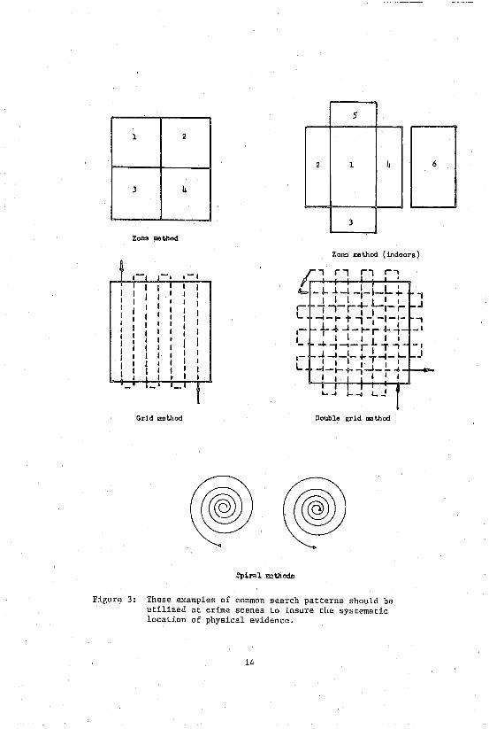
2. Search patterns should be systematic with the best results being obtained by employing a geometric pattern such as strip, grid, and zone as illustrated in Figure 3. The actions of the perpetrator at the scene should automatically suggest that certain types of ev:i.dence will be found. This Should be kept j,n m:i.nd as the search is conducted.
3. It is recommended that a second search of the crime scene be made within a reasonable period of time after the original search. Do not be in a hurry to give up the scene. Remember to kef!p the scene guarded by police personnel 24 hours a day until all processing is completed, as failure to do this results in the 106s of integrity of any evidence found after the original search.
4. All physical evidence should be photographed as it is found before it is handled in any way.
5. One member of the crime scene team should have the responsibility of being the physical evidence collector. This will mean that other members ~f the team will point out articles of evidence to the collector, and then the collector will secure these articles after they have been photographed and sketched. This system has the advantage of keeping the chain of eVidence short, thus eliminating unnecessary court testimony from other members of the team, and uniformity in packaging and individual article enumeration.
11

l-ooc-.::.-------------.z. ;1"11';
Figure 1: A rough sketch of a homicicie crime scene. Note that the inclusion of actual dimensions make the sketch confusing, so it is not suitable for court room use.
12

Go
Case 1J ID-76-0465-C Rocky Hill 0 Conn. April 9 0 1976
leal.: 112"· ,'8",,0 •.
T.V. SET
UTHROOM
orFICE
o o
[XIT
I -
z -3 -. -, -.. -
Figure 2: A finished sketch of a homicide crime scene. It is drawn to scale, and would be suitable for court room use. Note that the lack of measurements make the sketch easier to understand. When testimony is offered about the sketch, the investigator may respond to questions about dimension by simply measuring them on the sketch, using the proper scale as noted in the drawing.
13
LEGE.D =
aULlET
POCknl_
TOOTHP'C~
COIN
COIN
".~n"'TloN ,_
5
1 2
2 1 ~
J
J
ZOIl!3 ... thod
Zon:> ..,thod (indoors)
.-,
Grid "",thod Double grid ... thod
Figure 3: These examples of common search patterns should be utilized at crime scenes to insure the systematic location of physical evidence.
14
6

6. Fingerprints
a. Latent prints - the determination of whether to process an article of evidence for latent fingerprints at the crime scene or to package that article and submit i.t to the laboratory is largely dependent on the surface involved. If it is a porous surface, the laboratory is better equipped to process it with chemical methods. As such, the article should be packaged and submitted accordingly. However, if it is a smooth surface, fingerprint powder will adhere to the perspiration and oils left by the pores in the friction ridges of the fingers; this operation is easily performed at the crime scene.
i. Choose a fingerprint powder of a contrasting color to the surface being processed, i.e., chemist gray for dark colored surfaces, glass, mirrors or chrome; black powder for light colored surfaces. Pour a small amount onto a piece of paper to insure that the rest of the pOl,der does not get contaminated by the various objects dusted.
ii. Use a polyester brush for initial processing after first shaking out the excess pOl,der. Dip the bnlsh into the fresh powder and apply the brush to the object moving it in a rotary motion to pick up the circular patterns of the fingerprints. You l,i11 be aided in this process if a flashlight is held to the side and at a 101, angle to the area being processed. The fingerprint may be enhanced by brushing out exc-?ss powder betl,een the fricti.on ridges with a snort bristled camel hair brush.
iii. Number each latent print in sequence using a grease pencil or marker and record that information, as well as the location of the print, in notes. Photos should then be taken utilizing both one to one (actual size) and overall photography to show location relative to the object the print is on.
iv. Lift the fingerprint with transparent fingerprint tape and place it on a clear plastic slide. Position the tape so that it also picks up the grease pencil markings which will then
15

yield the print's identification number on the completed lift. In many instances, a second l~£t may provide better quality minutiae reproduction than the original lift.
v. Evidence to be processed at the laboratory should be packaged in a manner which avoids friction on the print-bearing surface. It is advisable to avoid simply placing the article in a plastic bag as this can also be a source of friction. The key to handling this kind of evidence is to immobilize the article in a fashion that allows transportation.
vi. General recommendations
(a)
(b)
(cl
Cd)
(e)
(f)
Do not dust visible prints; prints in paint, grease or blood. It will not make them ~ny clearer and may make them worse in quality. Do photograph tbem and transport the whole article to the lab.
Do not use the side of the dusting brush as it will smear the latent print. Do use only the end of the brush. --
~ dip the brush directly in the bottle containing the fingerprint powder. Do pour a small amount on paper - dip the bru~into that to insure that the whole bottle does not get contaminated with debris.
Do not process wet items. naturally.
Let them air dry
Do not use heat lamps or blowers to accelerate drying as they may cause excess evaporation of oils and perspiration.
Do allow items exposed to freezing temperatures to warm up before attempting to process them.
b. Post-mortem fingerprints - to obtain a positive identifioation of the deceased the investigator must first dry the fingers and palms of cadaver. They are then inked directly using an ink roller or pad and regular fingerprint ink. The individual fingers are then pressed into the IIFj.ngerprint Spoon, II (curved metal plate capable of holding a fingerprint card), and
16

released. Palm prints are taken by inking the palms in the same manner and then rolling a large cylindrical object, such as a beaker or bottle, 1;rapped in plain bond paper secured by elastic bands, over the palms of the cadaver.
i. If fingers are decomposed, as 1dth "floaters", technicians at the Forensic Laboratory should be asked for assistance as other methods may be utilized to obtain the fingerprints.
7. Impressions and Imprints
a. Shoeprints and tire prints will fall into two general categories:
i. Residue print - found on hard flat surfaces where the actual replica of the shoe or tire has been l~ft behind in a two dimensional form by residue deposited by the shoe or tire itself. This replica results from the shoe or tire contacting some colored medium such as dirt, grease, blood, mud, etc. and then being deposited by the article on the surface bearing the print.
ii. Impression print - results from a shoe or tire passing through a soft medium and then leaving a three dimensional negative replica of the original object making the print.
b. Recording the impression is a two-stage process. The first stage is to record it with photography.
i. The camera must be set up so that the film plane is parallel to the plane of the surface containing the impression. In addition, the camera must be located directly above (90°) the center of the print to avoid distortion. A tripod is recommended for this procedure. Careful attention to focus of the camera is mandatory to record the pertinent detail necessary for examination. Lighting should be set at an oblique angle to enhance and highlight the detail of the print. l"hile the camera is to remain stationary in relation to the impression, additional photographs should be taken after movinb the light source 90° to the next compass point until one full orbit has been completed. It is absolutely essential that a scale be included in the field of view of the camera and also that the camera be positioned so that the impression takes up the entire film format.
17

ii. The second process involves lifting the print itself, or making a positive replica of the impression through Plaster of Paris or silicone casting.
(a) Residue prints can be lifted through use of commercially manufactured lifters in the same fashion as latent fingerprints. Note: It is preferable that the investigator obtain the object bearing the impression and package the article in a manner to preserve the print and prevent its obliteration.
(b) A positive replica of an impression footprint or tire mark is made by plaster casting. This replica will often yield class characteristics for identification, but will seldom yield the necessary detail for an individualized identification unless unusual damage or wear to the tire or shoe has been reproduced in the CIISt. The procedure for making a plaster cast follows: (See also Figures 4 through 13).
1) The area to be cast should be examir.ed and large, loose articles of foreign matter should be carefully removed without disturbing the surface of the impression.
2) Because the material (such as soil or sand) to be cast is easily moved and damaged, it must be protected by spraying either lacquer or shellac onto a cardboard or paper held above the print at a 45° angle so that the sprayed liquid falls by gravity onto the print and protects it by hardening the surface to be cast. Approximately 15 minutes should be allowed as drying time.
3) A light sprinkling with talcum powder or spraying with silicone will facilitate separation of the plaster cast from the impression upon completion.
4) A physical barrier acting like a dam must be set up around the impression. Commercially manufactured steel frames are available for this purpose, but anything that will restrict the flow of the plaster and confine it to the immediate area of the print will suffice.
18

5) A rubber mixing bowl is recommended for the mixing of the Plaster of Paris as flexing of the bowl after pouring facilitates cleaning.
6) If the Plaster of Paris is at all lumpy, it should be sifted through a flour sifter or screen. An amount of water approximately equal to the print to be cast is placed in the mixing bowl. Plaster of Paris is slowly added to the water, stirring constantly Idth a spoon or spatula until the mj.xture has the consistency of pancake batter.
7) A pour can now be made by holding the bowl close to the print and deflecting the pouring liquid off of the spoon or spatula just before the liquid reaches the impressing. The pour is to be continued around the area of the impression until it has reached a depth of one half inch.
8) Reinforcement in the form of screen or wire should now be placed on top of the plaster. The investigator must exercise caution so as not to press the reinforcements into the plaster to the point where they interfere with the impression being cast.
9) The pour is now continued in the same manner as described until a thickness of one inch is reached. After allowing the cast to dry for approximately 10 minutes, identification Gata is scratched into the top of the cast and it is then allowed to complete the drying process. After the cast has been allowed to dry for 30 minutes, it can be removed from the impression. No attempt should be made to clean the soil from the bottom of the cast as it takes 14 hours for the complete drying process. The soil and debris which clings to the newly completed cast also makes an excellent known sample for soil comparisons on other evidence.
19
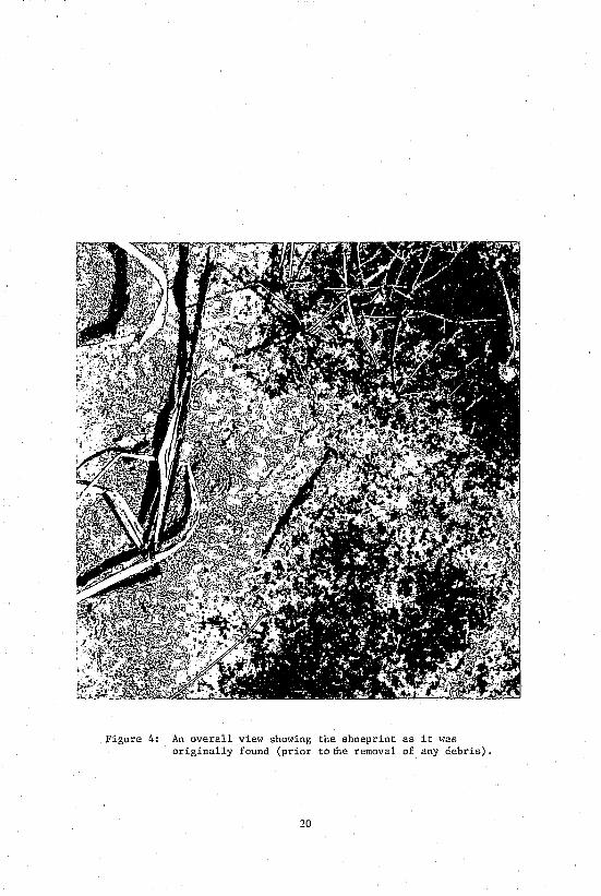
Figure 4: An overall view showing the shoeprint as it was originally found (prior tofue removal of any debris).
20

Figure 5: The camera must be placed directly over the footprint as shown to insure that no distortion will appear in the resultant photograph.
21

Figure 6: This photograph was taken in daylight with the use of a flash held at an oblique angle to insure the enhancement of detail in the footprint. Note that the inclusion of a scale makes possible examination from the photograph alone.
22
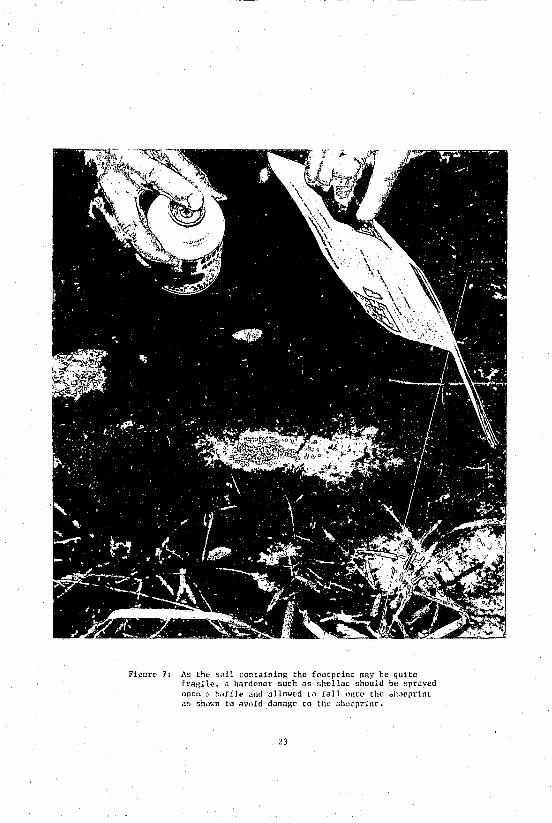
Figure 7: As the 5.111 containing the footprint may be quite fragile, a hardener such as shellac should be sprayed onto a baffle and "llO\;('d to fall <lnt(' the sh"eprint a~ shmm to avoid d~lma!-w to the shoeprint.
23

Figure 8: A physical barrier must be placed around the shoeprint to retain the Plaster of Paris as it is poured onto the shoeprint.
24

Figure 9: The plaster is added to water to make the necessary amount to cover the footprint to a thickness of approximately one inch. 1Vhen the mixture reaches the consistency of pancake batter, it is ready to be poured onto the footprint.
25

ligure 10: The Plaster of Paris should be poured into the mold by being deflected as shown to insure that the footprint is not damaged.
26

Figure 11: ~~en the thickness of the Plaster of Paris has reached approximately one-half inch, reinforcements are added to give strength to the finished cast.
27
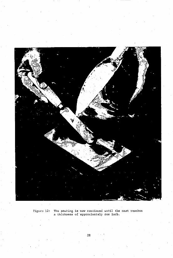
Figure 12: The pouring is now continued until the cast reaches a thickness of approximately one inch.
28

Figure 13: ~~en the cast is almost dry, the investigator should mark identification data into the cast itself.
29
8. Hair
10) The finished cast should be placed in a cushioned rigid container, wrapped in paper, and sent to the laboratory.
(c) Known standards - suspected shoes should be obtained as soon as possible to preclude additional wear markings appearing on the shoes and the possible obliteration of those already reproduced in the casting.
(d) Known standards - tires. As the original impression was mad" with the weight of the vehicle bearing upon the tire, the investigator must duplicate this condition when making the known standard for comparison purposes.
1) Jack the vehicle up so that the suspect tire clears the ground.
2) Ink the entire tread circumference of the tire with fingerprint ink.
3) Place an approximate 10 foot length of wrapping paper under the tire.
4) Let the vehicle down onto the paper and slowly drive it along the paper until the tire has completed one revolution.
5) Place identifying data including which tire made the mark (position on the vehicle) which side of the tire mark was facing inboard or outboard of the vehicle.
6) Repeat the entire process until all tires on the vehicle have been completed. It is necessary to submit the known standards to the laboratory along with the cast or photos of the tire impression. The submission of the actual tire, in most cases, is not necessary.
a. Usually individual hairs may be picked up by the fingers or by tweezers, however, this task may also be accomplished through the use of vacuum sweepers. The hair is then placed in a paper that is folded in the "druggist fold," which in tUl:n is placed in 2n envelope properly labeled with identification data and sealed (See Figure 14).
30
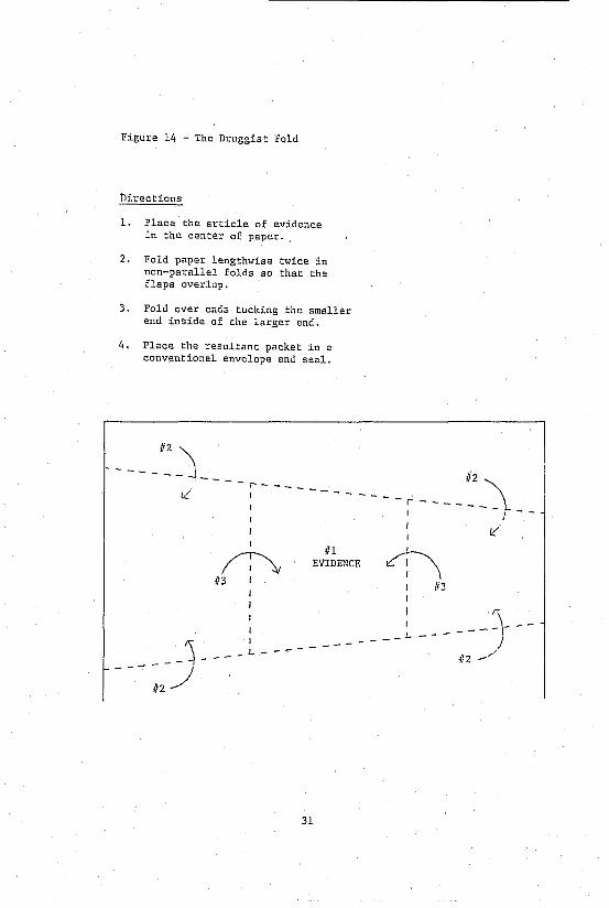
Figure 14 - The Druggist Fold
Directions
1. Place the article of evidence in the center of paper.
2. Fold paper lengthwise twice in non-parallel folds so that the flaps overlap.
3. Fold over end:; tucking the smaller end inside of the larger end.
4. Place the resultant packet in a conventional envelope and seal.
- - -- _112 "\
-----------r
I -.. - -- - - _I~_,\
- -- ---~ 112~
I
~ 113
III EVIDENCE
L--------
31
~~
I
_L
\ 113
---
I -
k:'

b. Known standards - the sample area should first be combed to remove all loose hairs. These loose hairs should be packaged separately. The standards should then be pulled so as to include the ruot. Head hair samples should be taken from tlie various parts of the head, i. e.. crOt-ln, neck, sides, front. Collect a minimum of 12 hairs. A less preferred method of obtaining standards is to cut the hairH as close as possible to the skin or scalp.
9. Fibers
a. Collection of fibers as evidence is best accompU,hed by pick ing up the fibers with the fing(>rs or with tweezers. It is also possible to collect fibers through use of a vacuum sweeper fitted with an in-line canister attachment in the hose. The canister must contain a filter that must be changed with each use. A third mt'lhod is to use tape to pick up this type of evidence. Picking up the evidence with fingers, tweezers, or tape has the advantage of not contaminating the samples.
h. Packaging - Vacuum sweepings should be placed in separate containers in accordance with their origin nnd labeled accordingly. If small amounts or individual fibers are picked up, place them in paper folded in the "drugr,isl fold," which is in turn sealed in a paper envelope labeled with identification data.
c. Other fiber evidence:
i. Cloth - photograph as to location and collect as evidence.
ii. Fabric marks - collect the entire article and then submit it to the laboratory. If this is impossible, photograph the marks with the inclusion of a scale or through use of one to one (actual size) photo equipment.
10. Debris - soil - safe insulation
Collection of samples - best taken directly from the footprint or tire mark after is has been photographed and cast. Two tablespoons of soil or debris are generally suffident. Additional samples of the same size should be taken from the four compass points surrounding the area of interest at a radius of a few feet and then a second set at a radius of 25 feet. The purpose of these samples is to determine the individuality of the area of interest. Samples should be
32

kept separate by being placed in clean cardboard containers. Careful notes should be maintained containing the origin of these samples. If the samples are not dry, they should be allowed to do so before being sealed in their respective containers. If the soil or debris is on a suspect's clothing, the clothing should be packed in paper I,ith paper between any folds or layers.
a. In hit and run cases, every effort should be made to preserve the chunks of soil commonly found at the scene. These should be packaged in cartons containing a cushioning of paper to preserve their condition for layering examination at the laboratory. lilien taking knmffi samples in this type of case, samples should be taken from all four fenders of the offending vehicle .''> the layering will vary considerably.
11. Glass
a. Photograph the fractures both generally and specifically as information such as direction of force and sequence of fractures may be determined. Be sure to include a scale.
b. With small articles, submit all pieces as a physical match may be possible.
c. With large articles, known standards from the area of the break must be taken for possible future comparison to glass found on any suspects. The known standards should be marked indicating I'hich side of the glass faced outside and which side faced inside.
d. If fingerprints are not a consideration, the glass should be packaged by taping the pieces to a rigid container after cushioning to prevent further damage. Be sure to submit all pieces as a physical match may be possible.
12. Paint
a. Photograph the area in question both with and without a scale.
b. Collection of paint evidence may be accomplished with the use of tape to insure getting intact pieces of the paint.
c. Known standards may be obtained by chipping the paint to the underlying surface, intact, to insure layer sequence. Allow these chips to fall into paper which is to be folded
33

in the "druggist fold", which in turn is placed in a labeled envelope and scaled.
1. Collect known standards adjacent to the area of interest to be used as a control and package in the same manner as previously mentioned.
13. Tool. marks
a. Begin by taking overall photos of the object containing the tool mark to show its nature and relationship to the scene.
b. Take a second set of photos that will show the tool mark specifically so that detail can be seen. (Note that as tool marks are three dimensional and photographs are two dimensional, examinations cannot be made from photos alone).
c. Collection of tool mark evidence
i. By far, the best method for comparison of tool marks is to secure the actual item containing the mark and submit it to the laboratory along with the suspected tool. Care must be taken to protect the working area of the suspect tool by wrapping it in paper. 'Jnder NO circumstances should the investigator attempt to fit the tool into the mark as it may destroy the very evidence that is to be examined by the expert.
ii. In dealing with large art'icles or non-removable articles, the tool mark itself may be cut out of the object bearing it. If this is impossible, the investigator has the option of making a silicone cast to the tool mark. Silicone is recommended for this replica as it will reproduce the necessary detail for examination. Plaster of Paris is NOT recommended for this type of casting. ---
(a) Silicone kits are commercially available and the individual kit instructions should be followed. The investigator may press the strings of an identification tag into the edges of the casting material in a way that will not affect the cast itself. This tag can then be filled out '~ith the proper identification data.
34

14. Firearms
a. Photograph the weapon as found at the crime scene and mark the location of thi: weapon on the sketch.
b. It must be noted that any weapon found at a crime scene may contain fingerprints. Bearing this in mind, the weapon should only be handled by the surfaces that normally would not yield fingerprints, i.e., checkered grips, edges of the trigger guard or knurled, finned or roughly machined surfaces manufactured into the weapon for the purpose of creating friction for gripping.
1. The investigator should also be alert for the presence of other trace evidence such as hair, blood, tissue, bone fragments, glass, and fibers. Under no circumstances should the weapon be cleaned or wiped off as this trace evidence may be destroyed. If the investigator suspects that this evidence may be present, this fact should be made known in the form of a request for trace examination to the person receiving it at the laboratory.
c. Notes should include information on: the time the weapon was found, the condition of the weapon (Le., safety on or off, hammer cocked, slide back, jammed, etc.), the
.position of any live rounds or cartridge casings near or inside the weapon, and all identification data on the weapon, i.e. make, model, caliber and serial number.
d. When picking up the weapon, DO NOT ALLOW ANYTHING TO BE PLACED IN THE BARREL.
e. Unload the weapon noting the location of fired and unfired cartridges. Sketch cylinder when dealing with revolvers, noting the type and condition of each chamber. Cartridge casings and bullets should NOT be marked in any way. They should be placed in individual envelopes, marked with identification data and then sealed. The purpose of this is to keep the bullets or casings from scratching each other thus altering or obliterating the marks that the firearms examiner will use for identification.
f. In dealing with pistols and other weapons that load from a clip, remember to unload the live round that may be in t.he chamber. It is not necessary to unload the live rounds from the clip after it has been removed from Lhe weapon.
35
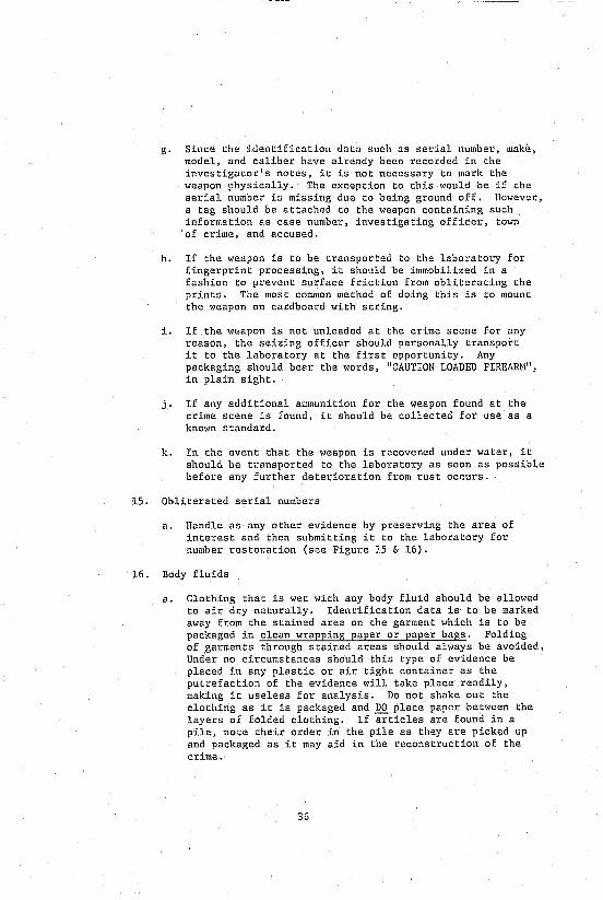
g. Since the :identification data such as serial number, make, model, and caliber have already been recorded in the investigator's notes, it is not necessary to mark the weapon physically. The exception to this would be if che serial number is missing due to being ground off. However, a tag should be attached to the weapon containing such information as case number, investigating officer, tOlm of crime, and accused.
h. If the weapon is to be transported to the laboratory for fingerprint processing, it should be immobilized in a fashion to prevent surface friction from obliterating the prints. The most common method of doing this is to mount the weapon on cardboard with string.
i. If the weapon is not unloaded at the crime scene for any reason, the seizing officer should personally transport it to the laboratory at the first opportunity. Any packaging should bear the words, "CAUTION LOADED FIREARH", in plain sight.
j. If any additional ammunition for the weapon found at the crime scene is found, it should be collected for use as a known standard.
k. In the event that the weapon is recovened under water, it should be transported to the laboratory as soon as possible before any further deterioration from rust occurs.
15. Obliterated serial numbers
a. Handle as any other evidence by preserving the area of interest and then submitting it to the laboratory for number restoration (see Figure 15 & 16).
16. Body fluids
a. Clothing that is wet with any body fluid should be allowed to air dry naturally. Identification data is to be marked away from the stained area on the garment which is to be packaged in clean wrapping paper or paper bags. Folding of garments through stained areas should always be avoided. Under no circumstances should this type of evidence be placed in any plastic or air tight container as the pulrefaction of the evidence will take place readily, making it useless for analysis. Do not shake out the clothing as it is packaged and DO place paper between the layers of folded clothing. If ~ticles are found in a pile, note their order in the pile as they are picked up and packaged as it may aid in the reconstruction of the crime.
36
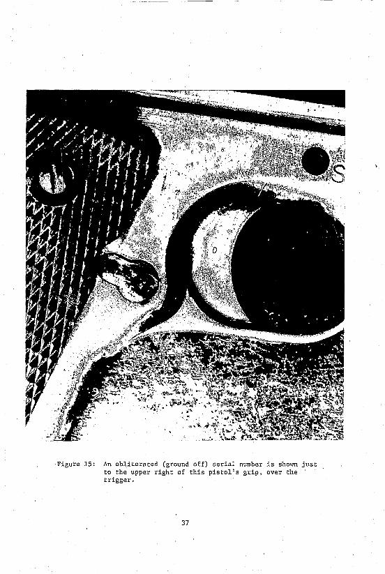
Figure 15: An obliterated (ground off) serial number is shown just to the upper right of this pistol's grip, over the trigger.
37

Figure 16: The obliterated serial number is vistble after being raised by members of the firearms section of the laboratory.
38
b. Blood (See Tables 4 and 5)
i. Liquid samples - if present, efforts should be made to collect a sample of it before it coagulates. Samples should be taken by using a clean pipette or medicine dropper. The blood should be placed in a sterile stoppered test tube with EDTA an anticoagulant and kept under refl,-igeration hut not frozen. The sample should be delivered to the laboratory as soon as possible. An alternate method is to place sterile gauze in the blood, allow it to dry and then package it in paper.
ii. Dried blood stains - if possible, the entire article containing the stain should be transported to the laboratory. If this is not possible, the stain should be cut out of the article and then packaged in paper. In those cases where the stain is on something solid and non-absorbent, there are two methods:
(a) The stain may be scraped off the article into a paper. This paper is then folded in the "druggist fold", placed in an envelope and sealed.
(b) The stain may be eluted onto cotton thread ",istened in saline solution by rubbing the thread on the stained area. The threads are then allowed to dry and are placed in a paper envelope which is then labeled and sealed. Always obtain a control by repeatlng the same procedu.-e in an area adjacent tu the suspected blood stain.
iii. Blood stains on Clothing - if the vic Lim is alive and it becomes necessary to cut the clothing off, avoid cutting through the stained area or holes that may have been caused by a bullet or weapon as this will destroy valuable physical evidence.
iv. Known standards - if it is possible to obtain two tubes of liquid blood sample from the victim and the accused, it should be obtained by a doctor - one tube should contain EDTA and one tube should have no anticoagulant. This step should not be overlooke,! by the investigator since the typing of liquid blocu samples greatly facilitates the information available to the case in terms of quick results and further management.
39

TABLE II
COLLECTION OF BLOOD STAINS AT CRI~lli SCENE
Blood Location
Crusts of dried blood
Stained knives, rocks
Upholstery, rugs (fabric)
Stains on walls
Small stains
Very small stains
Large stains
Clothing
Collection Hode
Scrape into clean vial
Scrape into paper envelope
Collect material from surrounding area as a control
Bring to lab intact
Cut out section and bring to lab
Cut out unstained section and bring to lab
Hoisten unused 3/8 inch cotton thread (/18) with water and swab stained area gently until thread has uniform deep red or brolffi color -- collect as many threads as possible
Also collect a control area
Let air dry in unstoppered vial
Use thinner thread
Scrape the stain into paper envelope
Air dry at room temperature
Keep out of direct sunlight
Put each item in a separate bag and staple shut -- never use plastic bags
40

TABLE 5
COLLECTION OF WHOLE BLOOD AT CRIME SCENE
Blood Condition
Fresh-wet-not clotting
Fresh-wet-thick-clotting
Wet blood from suspects
Collection Hode
Use hyprosyringe - Put blood into EDTA vial
Disposable glass pipette equipped with suction bulb - Put bll,Jd into EDTA vial
Add equal volume physiological saline to preserve red blood cells
Coll"ct 2 tubes EDTA (not NAF) - one with anticoagulant - the other without any anticoagulant
Transport to lab
Keep cold if overnight storage is necessary Do not freeze
41
v. Blood patterns - It is necessary to photograph blood patterns regardless of whether the sample is liquid or dried in order to facilitate the reconstruction of the crime. Much information can be gained through the study of these patterns, 1. e. , direction of blood flight, objects or persons present or absent during the crime, motion of victim or '..teapon, etc.
vi. Field tests for blood (presumptive)
A positive reaction by any of the following tests will only indicate the possible presence of blood. Suspect stains should then be subjected to confirmatory crystal tests at the laboratory. If the chemicals have been tested On known standards of blood prior to testing on the suspected blood stains, the lack of a reaction on the unknown stain can be deemed as absent blood. A positive reaction only indicates the possible presence of blood and does not indicate the species of the donor. Since all presumptive tests are subject to false positive reactions, confirmatory testing is performed at the laboratory.
(a) Phenolphtalin (Kastle-Mayer reagent) - conducted by rubbing a cotton swab that has been moistened in a saline solution on the suspected blood stain. A drop of the phenolphtalin-alcohol reagent is added to the swab, and then a drop of hydrogen peroxide. A positive reaction will turn the swab pink within 20 seconds.
(b) Leuco Malachite Green Test (LMG) - performed by rubbing a saline moistened swab on the suspected blood stain and then applying the prepared reagent and hydrogen peroxide to the swab. A positive reaction is indicated by a greenish-blue color that will appear almost immediately.
c. Ortho-Tolidine Test - A~plication is similar to other presumptive test reagents. A F)sitive reaction is indicated by an intense blue color. There are reports to indicate chis reagent might be carcinogenic.
42
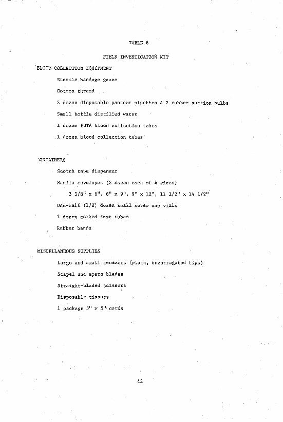
TABLE 6
FIELD INVESTIGATION KIT
BLOOD COLLECTION EQUIPMENT
Sterile bandage gauze
Cotton threa.d
2 dozen disposable pasteur pipettes & 2 rubber suction bulbs
Small bottle distilled water
1 dozen EDTA blood collection tubes
1 dozen blood collection tubes
:ONTAINERS
Scotch tape dispenser
Manila envelopes (2 dozen each of 4 sizes)
3 3/8" x 6", 6" X g", g" X 12", 11 1/2" x 14 1/2"
One-half (1/2) dozen small screw cap vials
2 dozen corked test tubes
Rubber bands
MISCELLANEOUS SUPPLIES
Large and small tweezers (plain, uncorrugated tips)
Scapel and spare blades
Straight-bladed scissors
Disposable tissues
1 package 3" x 5" cards
43
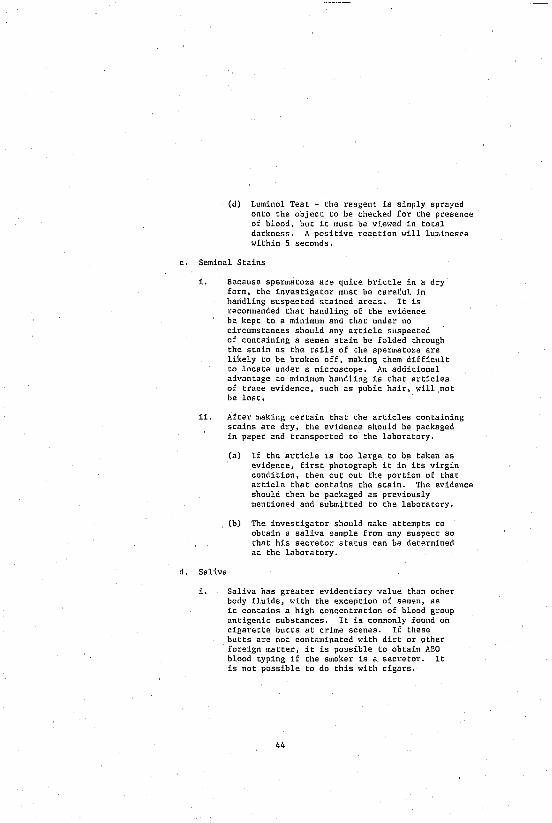
(d) Luminol Test - the reagent is simply sprayed onto the object to be checked for the presence of blood, but it must be viewed in total darkness. A positive reaction will luminesce within 5 seconds.
c. Seminal Stains
i. Because spermatoza are quite brittle in a dry form, the investigator must be careful in handling suspected stained areas. It is recommended that handling of the evidence be kept to a minimum and that under no circumstances should any article suspected of containing a semen stain be folded through the stain as the tails of the spermatoza are likely to be broken off, making them difficult to locate under a microscope. An additional advantage to minimum handling is that articles of trace evidence, such as pubic hair, will not be lost.
ii. After making certain that the articles containing stains are dry, the evidence should be packaged in paper and transported to :he laboratory.
(a) If the article is too large to be taken as evidence, first photograph it in its virgin condition, then cut out the portion of that article that contains the stain. The evidence should then be packaged as previously mentioned and submitted to the laboratory.
(b) The investigator should make attempts to obtain a saliva sample from any suspect so that his secretor status can be determined at the laboratory.
d. Saliva
i. Saliva has greater evidentiary value than other body fluids, with the exception of semsn, as it contains a high concentration of blood group antigenic substances. It is commonly found on cigarette butts at crime scenes. If these butts are not contaminated with dirt or other foreign matter, it is possible to obtain ABO blood typing if the smoker is a secretor. It is not possible to do this with cigars.
44

Additional evidence containing saliva may include toothpicks and chewing gum. When handling this form of evidence, the investigator should take care not to handle it on the stained area as it may be contaminated by the perspiration of the evidence col1ector.
ii. Known origin saliva samples should be obtai11ed from rape victims and suspects alike to determine their secretor status. They may be collected directly in clean filter paper by allowing the fluid to dry and then circling the stained area with pencil.
(a) An alternate method is to have the donor chew either a small piece of filter paper or sterile gauze until it is saturated with saliva, allow it to dry, and then place the sample in a labeled paper envelope and submit it to the laboratory.
(b) Liquid saliva sample could be collected into a test tube.
e. Other body fluids
i. Approximately 80% of the population are secretors. ABO blood group antigens can be found in their body fluids such as perspiration, saliva, urine, tears, mucus, feces, and vaginal secretions. These antigens can be identified at the laboratory and the blood group of the donor can be determined.
ii. As most body fluids encountered in crime scene processing are in the form of dried stains, they should be handled in the same manner as dried blood stains. If possible, the stained object should be submitted to the laboratory. If this is not possible, the stained area should be cut from the object and packaged in paper in a fashion to avoid folding it through the stain. In this instance, a portion of the object that is not stained should also be cut from the object and submitted to the laboratory for use as a standard. Thts standard should be packaged separately.
(a) If the samples are in liquid form, they should be collected in glass containers and sealed. No preservatives are necessary.
45
17. Accelerants
a. Suspected accelerants at arson scenes should be collected by the investigator as soon as conditions at the fire scene permit. By their very nature, accelerants will tend to'evaporate quickly, therefore, articles suspected of containing them must be placed in airtight metal containers as soon as possible.
b. Containers. The preferred type of container is a new metal paint can. The investigator must bear in mind that the container must remain airtight and that many accelerants dissolve plastic and rubber. Glass jars are acceptable but should be packaged in a manner to avoid breakage of the container itself. l~en choosing a container for arson evidence, choose one that will allow head space within the container to allow the accelerant to evaporate into. It is from this head space that samples will be taken for analysis at the laboratory. (See Figure 17)
c. Crime scenes. The investigator must bear in mind that it is of utmost importance to locate the point of origin and all of any mechanical, ~hemical, or other simple devices used to ignite the acceleraTIt or to spread the fire (trailers). It is also possible that, due to the intensity of the fire or the nature of the accelerant, there will be no traces of the accelerant readily detectable. As such, aDsorbent materials in the area of the point of origin should be sampled and packaged as mentioned above. Absorbent materials may include wood floors, wall board, wood paneling, soil, fabrics, paper, and debris. It is quite likely that these materials will contain traces of the accelerant.
i. Liquids. Collect them in a glass jar or small, clean, airtight test tube.
18. Documents
a. Questioned samples. The investigator must exercise care in the handling of document evidence, particularly regarding the presence of latent fingerprints. The document must be handled as little as possible while being placed in a clear plastic envelope. Tweezers or tongs should be employed for this task to avoid the investigator's fingerprints appearing on the evidence. No additional folds should be made nor should the investigator mark any identification data on the face of the document. As document evidence
46

Figure 17: The gas chromatograph, which is used to examine arson evidence, is shown here.
47
is not automatically processed for fingerprints, if this is to be a considera:ion, the submitting agency should so indicate in their letter of transmittal. This letter should be affixed to the outside of the envelope containing the evidence. It is necessary to inform the laboratory of the dual processing as the chemical processing for latent prints will cause the paper to discolor and may also dissolve certain inks. Therefore, the document must be photographed by the laboratory prior to the application of the fingerprint processing chemical.
b. Known standards. The most important thing for the investigator to remember is to duplicate the conditions under which the questioned document was made as closely as possible regardj.ng writing instrument, type and size of paper, context of the written message, and writing type or style. Known standards should be dictated to the suspect by the investigator to preclude the suspect seeing and then imitating the questioned sample. The known samples should be removed from the view of the suspect as soon as they are written. The suspect should be encouraged to write the entire questioned sample verbatim several times, if possible, until the investigator is satisfied that the subject is writing naturally and has given up any attempt to disguise the sample. Additionally, the suspect should be required to repeat the process using the unnatural hand. There should be no attempt to assist the suspect in spelling or with grammar. Seat the suspect in a chair placed at a table to insure comfort and natural writing conditions. The situation in which the suspect has been placed is inherently stressful, since the sample is to be used in a police investigation. Efforts to obtain samples that are commonly found on documents filled out in the usual course of business should be made. (See Table 7 for suggested handwriting sources). These samples will normally be free from any attempts at disguise and for this reason may be superior to the requested samples.
i. Known standards for typewriters or business machines. ALtempts should be made to secure the suspected machine and to submit it to the laboratory along with the questioned sample. If this is impossible, at least three reproductions of the text of the questioned sample and three reproductions of all the characters on the suspect machine should be made. The investigator should not overlook the fact that many typewriters now use "one time" ribbons. Such a ribbon could have the text of the message being examined embosed on it. In such an instance, the ribbon should be taken off the machine and submitted as evidence.
48

TABLE 7
"'HERE TO FIND HANDWRITING SAHPLES
Sources of Genuine Writings
1. Ci ty Records Building Deparement permits City Auditor: canceled checks City Clerk: licenses (peddler, tavern, special permits, etc.); voters
registration lists Personnel Department: Civil Service applications
2. County Records County Clerk: Civil Service applications, claims for services or
merchandise, fishing, hunting, marriage licenses Department of Taxation: State income tax returns Purchasing Department: bids and contracts Register of Deeds: deeds, birth certificates, public assistance
applications, ID card applications Selective Service (local board): registrations appeals
3. Deparement Store Records Complaints and correspondence Credit applications Receipts for merchandise Signed sales checks
4. Drug Store Records Register for exempt narcotics, poisons
5. Education Documents Applications for entrance Athletic contests Daily assignments Ex~mination and research papers Fraternity and sorority records Receipt for school supplies (laboratory, athletic gear) Registration cards and forms Federal and Seate Loan and Grant applications
6. Federal Records Customs documents: immigration and naturalization records Department of Justic~ (FBI): fingerprint cards, National
fradulent check file, checkwriter standards file, safety paper standards file, rubber stamp and printing standards file, typewriter standards file
Hilitary re~ord~ Patent office applccations Post Office Department: P. O. box application, registered and special
delivery receipts
49

TABLE 7 (CONTINUED)
Social Security Administration: applications for numbers, benefits
U.S. Treasury: canceled payroll checks Veterans Administration: application for benefits (veterans and
widows)
7. Financial Documents Canceled back checks Contracts and related correspondence Credit applications, for example, to a department store Deeds Deposit slips Expense accounts Insurance documents including health and accident Lease agreements Loan companies records Microfilm bank records Pension applications and checks Promissory notes Safety deposit vault register and applications: bankruptcy
proceedings, cash received slips, withdrawal slips Title companies documents
8. Hospital Records Admission releases
9. Library Records Applications for cards
10. Miscellaneous Documents Administrator, estate Airplane logs Answers to decoy letters Architects plans Asylums Auctions Bail Bonds Building after hour registers Close associates Complaint bureaus generally Copyright applications Death certificates Decoys. deliber receipts, return recei.pts for registered mail Exchanges Express company. cartage, mover's ree.eipts Express records and receipts Furniture contracts Guardian Janitors (wastepaper) Legal papers, generally Messengers receipts Neighbors Newspaper reporters
50
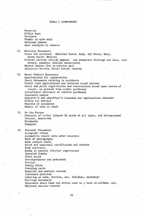
TABLE 7 (CONTINUED)
Notaril!s Office boys Partners Permit to open mail. Railroad passes Rent receipts to tenants
11. Military Documents Bases and stations: National Guard, Army, Air Force, Navy,
Coast Guard, Harines General service related papers: tax exemption fillings and lean, real
estate, pension, medical educational R~cord depots (for ex-service men) Selective Service (draft board) records
12. Hotor Vehicle Documents Applications for registration Court documents relating to accidents Credit card applications and invoices based thereon Hotel and motel registration and reservations based upon routes of
travel, as gleaned from credit purchases Installment contracts on vehicle purchases Insurance papers Operator's and chauffeur's licenses and applications therefor Orders for service Reports of accidents Report of loss or theft
13. On the Person Contents of wallet (signed ID cards of all types, and photographs) Letters, postcards Notebooks Passport
14. Personal Documents Autograph albums Automobil.e repair work order receipts Back of photographs Bank account books Birth and baptismal certificates and records Book contracts Books in general (fly~.eaf signatures) Canceled checks Check stubs Correspondence and postcards Diaries Family Bible Greeting cards Hospital and medical records Insurance policies Labeling on cans, bottles, etc. (kitchen, workshop) Harriage documents Memoranda about home and office such as a note to milkman, etc. Hilitary service records
51

TA~LE 7 (CONTINUED)
Pages of photograph albums Passports Personal notebooks Prescriptions Rent receipts (receipts in general, i.e., movers, credit) School yearbooks Telephone and correspondence listings Wills
15. Police Sheriff's Department Records and General Criminal Documents Arrest Records (including fingerprint cards) Complaints and reports to police departments, sheriffs, district
attorneys, etc. Court of Claims Court clerks Exemplers obtained incident to booking procedures Jail and penitentiary records Jury records Juvenile Court Parole and probation reports Receipts for returned property l~ritings obtained by other agencies in prior investigations Writings obtained by your own agency in prior investigations
16. Public Utility Records (Corporate Documents) Applications for service: cable television, electricity, garbage,
gas, telephone, water Book of account Invoices Hinutes Original telegram messages Reports to intre and interstate and commerce agencies
17. Real Estate Records Property listing agreements
18. Relatives Letters and c~rds of all types
19. Social, Recreational, Fraternal Documents Documents relating to; civic organizations, clubs (luncheon, sports,
etc.), loges, nonprofit groups, political groups, PTA organizations, r~ligious organizations
20. State Records Conservation files: boat, fishing, hunting licenses Corrections files: probation and parole reports Incorporation documents (these filed with state agencies) Hotor vehicle files: drivers files, title files Personnel files: Civil Service applications and examinations Secretary of State: applications for notary public State Treasurer: canceled checks Taxation files: beverage and cigarette tax applications
52
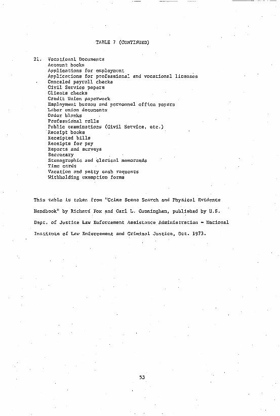
TABLE 7 (CONTINUED)
21. Vocational Documents Account books Applications for employment Applications for professional and vocational licenses Canceled payroll checks Civil Service papers Clients checks Credit Union paperwork Employm~nt bureau and personnel office papers Labor union documents Orde1.' blanks Professional rolls Public examinations (Civil Service, etc,) Receipt books Receipted bills Receipts for pay Reports and surveys Secretary Stenographic and clerical memoranda Time cards Vacation and petty cash requests Withholding exemption forms
This table is taken from "Crime Scene Search and Physical Evidence
Handbook" by Richard Fox and Carl L. Cunningham, published by U.S.
Dept. of Justice Law Enforcement Assistance Administration - National
Institute of Law Enforcement and Criminal Justice, Oct. 1973.
53

i1. Charred Documents. Because of the fragile nature of this particular evidence, care must be exercised in picking up and packaging. The best method of picking up charred documents is to slip a thin but stiff piece of paper under the evidence and then place it in a cotton cushioned ca"cdboald container that will allow complete protection witilOut crushing it.
iii. Indented Writing. This type of evidence should be handled in the same fashion as charred documents, i.e., package in a manner to prevent crushing or flattening of the evidence. Only the container holding the evidence should be marked by the investigator. Under no circumstances should pencil be applied to the evidence in an effort to make the text legible as this will likely destroy it. The best method of viewing the text is to view it with a light source held at an oblique angle to ehe document and then to record the message with photography.
19. Voice Identification
a. Questioned sample. In the vast majority of cases, the only equipment needed to obtain the unknown sample (telephone cfllls) is a good quality recorder and an induction telephone pickup coil. The victim can easily be taught to activate the recorder as the telephone rings for each incoming call. If the call is recorded by an automatic system as is con~on1y found in a police or fire department, it becomes necessary to make a second or dubbed recording for laboratory analysis. This is accomplished through the use of a second recorder and a patch cord attached directly between both recorders, thus eliminating any noise occurring in the environment of ehe recorders. If this method is utilized, no Significant information for identificatio~ is lost. Should there be an absence of jack outlets on the original recording machine, the microphone for the second recorder may be placed in front of the speaker of the original recorder. This is the least desirable method as the resultant tape will now contain any additional noise present in the recording site plus a loss of information that was present on the original tape. Should this seem to be the only method available, the Voice Identification Unit of the Laboratory should be c.:>nsultcQ. for an alternate means of recording the sample.
b. Known samples. It is 01 primary importance that the context of both samples be identical. Random conversations will not be sufficient for comparison purposes. Th~ investigator should make eY.'!lY effort to duplicate the questioned
54

sample as closely as possible regarding context and conditions under which it was recorded, 1. e., telephone, live conversation, or radio. Remember thar. while the quality of the questioned sample cannot be controlled, in many instances the quality and the environment in which the known sample is recorded can. To insure uniformity between the samples, efforts should be made to record them in surroundings that are free from other sounds which may mask the ,~amples. It is necessary in longer samples to have a transcription of the unknown sample. This will assist the investigat01: in obtaining a known sample and will also assist the Voice Identification Technician in examining the samples. The investigator should make every effort to insure that the suspect repeats the context duplicating inflection, speed, and, if possible, the emotion shown in the unknown sample. As reading out loud produces flat, robot-like samples, it is preferable that the investigator read the sample, a phrase at a time, to the suspect for repetition by that suspect. The entire sample shuuld be repeated for the recording three times so that it io a mure natural sample of the suspect's normal speaking habits. It is perfectly permissible to have the investigator's voice on the tape as well as the suspect's voice. The tape should be prefaced wj,th information containing the identity of the speaker, who is present, and the date and time of the recording. Known samples may be obtained -- voluntarily or by court order. Should the investigator need more information on methodology, he may contact the Voice Identification Unit at the Laboratory.
55

PART THREE
EVrDEtlCE SUBMISSION

III. EVIDENCE SUBHISSION TO THE LABORATORY
After packaging evidence as indicated, it is necessary to draft a cover letter or letter of transmittal to the Laboratory. In this letter should be information as to the nature of the case, date, location, suspect or accused, and the victim's identity. The letter should also include an inventory of all the evidence submitted, listed by exhibit numbers .. hich shall run in consecutive order for all the evidence in the case, even if it is not submitted at that particular time. All examinations on articles of evidence should be specifically requested. The formats, sho..u in Figures 18 and 19, are recommended.
56
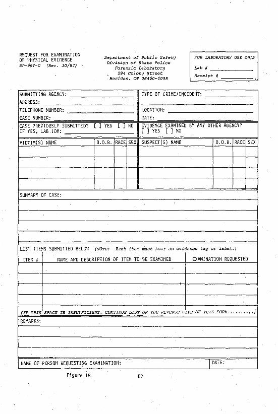
REQUEST FOR EXAr~INATION OF PHYSICAL EVIDENCE SP-997-C (Rev. 10/83)
SUBMITTING AGENCY:
ADDRESS:
TELEPHONE NUMOER:
CASE NUMBER:
CASE PREVIOUSLY SUBMITTED? IF YES, LAB 10#:
VICTIM(S) NM1E
SUMMARY OF CASE:
LIST ITEMS SUBMITTED BELO\<:
Department of Public Safety Division of State Police
Forensic Laboratory
FOR LABORATORY USE ONLY
Lab H _--'-____ _ 294 Colony Street
Meriden, CT 06450-2098 Receipt
TYPE OF CRIME/INCIDENT:
LOC,ATTON:
DATE:
[ ] YES [ ] NO EVIDENCE EXAMINED BY ANY OTHER AGENCY? [ ] YES [ ] NO
D.O.B. RACE SEX SUSPECT(S) NAME D.O.B. RACE
(NOTE: Each item must bear an evidence tag or label.)
SEX
ITEM Ii NAME AND DESCRIPTION OF ITEM TO BE EXAMINED EXAMINATION REQUESTED
(IF THIS SPACE IS INSUFFICIENT, CONTINUE LIST ON THE REVERSE SIDE OF THIS FORM .•........ J
REMARKS:
t----
NAME OF PERSON REQUESTWG EXAHINATION: 1 DATE:
Figure 18 57

CONTINUATION OF LIST OF ITEMS SUBmTTED
ITEM # NAME AND DESCRIPTION OF ITEM TO BE EXAMINED I EXAMINATION REQUESTED
Figure 18 continued 58

HOOle of Co 11 ecti ng Agency:
Case Humber. Iiten Humber.
~iptlon of I tern:
Locati 00 Where I tern "las Found:
Co 11 ected 6y: loate:
EVIDENCE TAG
Figure 19: Suggested Format of an Evidence Tag (giving the minimum information required).
59
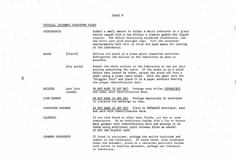
m o
TABLE 8
PHYSICAL EVIDENCE PACKAGING CHART
ACCELERANTS
BLOOD
BULLETS
LIVE ROUNDS
(liquid)
(dry stain)
(not live rounds)
CARTRIDGE CASINGS
CLOTHING
CHARRED DOCUMENTS
Submit a small amount in either a metal container or a glass bottle capped with a top without a plastic gasket-for liquid samples. For debris containing suspected a~celerants, use new paint cans with airtight tops. Fill the container approximately half full to allow for head space for testing at the laboratory.
Collect and place in a clean glass stoppered container. Refrigerate and deliver to the laboratory as soon as possible.
Submit the whole article to the laboratory or cut out that portion containing the stain. If the stain is on a solid object that cannot be taken, scrape the stain off into a paper using a clean razor blade. Fold the paper into the "Druggist Fold" and place it in a paper envelope bearing the proper identification data.
DO NOT MAJlX IN ANY WAY. Package each bullet SEPARATELY and label with identification data.
DO NOT MARK IN ANY WAY. Package separately in envelc~es to preserve any markings on them.
DO NOT MARK IN ANY WAY. Place in SEPARATE envelopes, seal and mark with identification data.
If wet with blood or other body fluids, air dry at room temperature. Do no accelerate drying with a fan or heater. Mark garment with identification data and package it in PAPER using additional paper between folds as needed. DO NOT USE PLASTIC BAGS.
If found in container, package the entire container and submit to the laboratory. If found loose, slip cardboard under the document, place in a container partially filled with cotton to restrict movement, package and transport to laboratory.

'",
I-'
PHYSICAL EVIDENCE PACKAGING CHART (continued)
DOCUMENTS/CHECKS
FINGERPRINTS (latent)
(visible)
FIREARMS
GLASS
HAIR AND FIBERS
PAINT
PLASTER CASTS
Place in plastic envelope using tongs or tweezers. Seal envelope after placing label on the face of the envelope containing identification data. DO NOT HAh~LE THE DOCUMENT WITH FINGERS AS IT WILL RUIN FINGERPRINT EVIDENCE.
Immobilize article in a way to prevent friction on the fingerprint bearing surface. Submit the entire article to the laboratory.
Photograph and then submit entire article to the laboratory. DO NOT ATTEMPT TO PROCESS BY DUSTING ~TH FINGERPRINT POWDER.
Unload the weapon taking care not to ruin possible latent fingerprint evidence. Note manufacturer's name, caliber, model, serial number and the presence or absence of ammunition and shell casings. Immobilize the weapon by mounting it on cardboard with string and transport to the laboratory. During this process, the weapon should be handled by the checkered grips or edges of the trigger guard.
Package in paper, taking care to protect any broken edges in case it is possible to make a physical match. Place wrapped glass in a solid protective container labeled with identification data.
Place samples in paper folded in the "Druggist Fold". The paper is then placed in an envelope and sealed. The proper identification data is then placed directly on the envelope.
Handle as hairs anti fibers. If the chips are large and a physical match is possible, the chips must be protected by placing them in a pill box or other protective container.
Package in a large firm container containing newspaper to cushion the cast and prevent breakage. Do not attempt to clean the bottom of the cast as damage may result. Identification data should be marked into the cast before it is completely hardened.
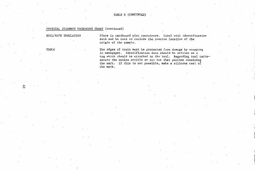
a'"
TABLE 8 (CONTINUED)
PHYSICAL EVIDENCE PACKAGING CHART (continued)
SOIL/SAFE INSULATION
TOOLS
Place in cardboard pint containers. Label with identification data and be sure to include the precise location of the origin of the sample.
The edges of tools must be protected from damage by wrapping in newspaper. Identification data should be written on a tag which should be attached to the tool. Regarding tool markssecure the entire article or cut out that portion conaining the mark. If this is not possible, make a silicone cast of the mark.

PART FOUR
LABORATORY EXAMINATION OF PHYSICAL EVIDENCE

IV. LABORATORY EXAHINATION OF PHYSICAL EVIDENCE
In recent years, there have been rapid advances in scientific knoWledge and instrumentation techniques. These advances have found their way into and become an important integral in the scientific criminal investigation. For example: Lasers are now being used in SOil, glass, and fingerprint examinations, X-Ray powder diffraction, atomic absorption spectroscopy, and SEN-EDX have been used extensively for the identification of chemicals, metals, and other trace. TLC, LC, GC, GC-HS, and HPLC are used routinely in drug, explosive, and arson cases. Cellulose acetate electrophoresis, starch gel electrophoresis, immunoelectrophoresis, immunofixation, crossed immunoelectrophoresis, electrofocusing, isotachophotesis, and two dimensional electrophoresis have provided powerful and sensitive tools for examination of blood, hair roots. seminal stain, tissues, and other physiological evidence.
PART FOUR is devoted to briefly Introducing the current state of the art in various areas of forensic science and the newest developments in the criminalistics field and by no means is it to he considered complete.
A. Accelerants
1. Types of accelerants
a. Petroleum distill.ltes: Nest accelerants fall into this cat~gory.
1. Straight run products: Those mixtures which are produ~ed during the distillations process with little further processing. These include light~r fluid, kerosene, fuel oils, and others.
ii. Processed products: Extra steps in the distillation ptoce~s are necessary for the production of benzene, toluene, gasolines, and other products.
b. Non-petroleum a~cclerants: Tutpentine, alcohOls, and mineral spirits.
2. Laboratory analysis of accelerants
a. Visual examination: All evidence is quickly macroscopically and microscopically examined for other types of physical evidence.
b. Liquid sample analysis: These may be used as supplied or "dried" as necessary ..
63
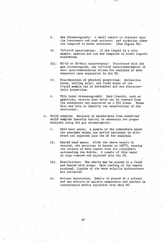
i. Gas chromatography: A small sample is injected into the instrument and peak patterns and retention times are compared to known standards. (See Figure 20).
ii. Infrared spectroscopy: If the liquid is a pure sample, spectra are run and compared to known organic substances.
iii. GC-IR or GC-Mass spectroscopy: Interfaced with the gas chromatograph, the infrared spectrophotometer of mass spectrophotometer allows for analysis of each component upon separation in the GC.
iv. Determination of physical properties: Refractive index, boiling point, and flash point of the liquid sample can be determined and are characteristic properties.
v. Thin layer chromatography: Hany liquids, such as gasolines, contain dyes which can be removed from the accelerant and separated on a TLC place. These dyes may help to identify the manufacturer of the acceleran t.
c. Solid samples: Recovery of accelerants from submitted solid samples (usually debris) is necessary for proper analysis using the gas chromatograph.
i. Cold head space: A sample of the atmosphere above the specimen within the sealed container is withdrawn and injected into the GC for analysis.
ii. Heated head space: After the above sample is removed, the container is heated to lOO·C, causing the release of more vapors into the atmosphere surrounding the debris. A sample of this vapor is also removed and injected into th~ GC.
iii. Distillation: The debris may be placed in a flask and heated with steam. Upon cooling of the vapors produced, liquids of the more volatile hydrocarbons are collected.
iv. Solvent extraction: Debris is placed in a solvent and the mixture of soluble components and solvent is concentrated before injection into this GC.
64
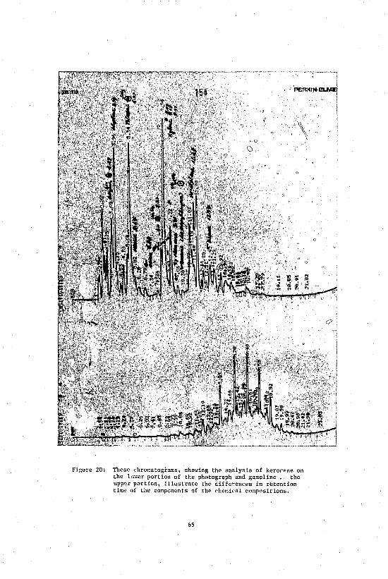
',----" ~·-·~--1 I
. ! -'PflRl<~i
Figure 20: These chromatograms, showing the analysis of kerorp.ne on the lOHer portion of the photograph and gasoline. the upper portion, illustrate the diffe~ence5 in retention time of the comp"n~nts of the chemical compositions.
65
I J
o

3. New Developments
a. Carbon adsnrption: Debris is heated and the vapors released are passed through a charcoal tube which will adsorb these components. Extraction from the carbo is then performed. The recovery of this method is extremely high.
h. Capillary column (see Figure 31).
B. Blood
1. Identification of blood
a. Presumptive tests: These tests are based on ~he reaction of a portion of hemoglobin with chemical reagents, such as o-tolidine, phenolphthalin, luminol, benzidine, and leucomalachite green.
b. Confirmatory tests: These are not as sensitive as the presumptive tests, but are necessary to prove that the suspect stain is, in fact, blood.
1. Hicrocrystal tests: Chemical reagents react with heme components of the blood producing characteristic crystals.
ii. Chromatographic test: Paper or thin layer chromatography is used to identify hemoglobin.
iii. Spectral tesl: Instrumental analysis based on the way hemog~obin absorbs light.
iv. Immunological test: Anti-human hemoglobin is used. This test also confirms that the blood is human.
2. Species tests
These tests determine the origin of a bloodstain. In the immunological precipitin test, anti-serum for a particular species, such as anti-human serum, gives a visible reaction ~·,~I;h serum nt'oteins.
3. Blood typing in dried bloodstains
\'nricus antigens, antibodies, and serulil. ptoLeints can be identified in blood evidence. Factors such os the ". e and condition of the stain affect testing.
a. Detection uf antibodies in serum (Lattes test): Addition of red blood cellE! of kno'''I1 type causes them to bp. agglutinated if antibodie& against them are present in the stain.
b1i
b, Detl!ction of blood group antigens: Three methods hEv,' been used for the detection of nn antigen on the red cell surfaces. (Spo Table 9) They ar~:
i. Absorption - Inhibition
ii. Absorption - Elution
iii. Mixed Agglutination
c. Typing of red blood ~ell isoenzymes: Separation of genetic markers a, ~he red cells based on the electrophoretic mobility of lhese substances gives additional grouping information. (TAble 10)
d. Typiilg of serum proteins: Separation of serum proteins by electrophoretic and detection by immunofixation techniques. (Table 11)
4. New developments
Hany nel' dt!velopments have "ccut· ed for ar,alysis of different genetic markers:
a. Jsoe'lectric focusing: Separation of protein mixtures on the basis of diUerences in their isoelcctric points. For example. the typiuI; of red cell PGH by isoelectt Ie focusing shol's 10 differellt patterns lr,stead of the 3 patterns seen with regular electrophorc>.l~. (Figure 21)
b. Hulti-system electrophoresis: Several genetic markers are analvzed by single electropiwresis run. For example. PGH. EsD' and GLO systems can be "'ped with a single bloud thread.
c. Gm and Km SYStt:!U1: ute Q~r\,1rll prvtein Gm .aud Km factors can be typed by means of specific antibodiLs. These markers have reportedly belm typed in bloodstains several decades old.
d. HLA system: Human leucocyte antigen system consists cf a large nl'Uloer 1'1 iactor~ iilul I..ht::,t= rctl. .. Lvr~ ar.: r;.ct only found on white ulood cells. but also on tissue.
e. Sexing of bloodstain: RIA (Radio-Irr~unoassay) - immuno assay techniqlles have been used teo J,'tect the male and female hormones.
T?ble 12, follotdng, shows the current state 'f the art in eKaminaUom, of blood evic!ence.
67

TABLE 9
BLOOD-GROUP SYSTE~!s
The approximate values for the white and black populations in the United States for many of the systems are shown in the following table.
Approximate occurrence, %, In U.S. EOEulations
RED CELL SYSTEH TYPES WHITE !I.LACK
ABO A 40 27 B 11 20 0 45 49 AB 4 4
Rh Rho 2 48 Rh1rh VI 20 RhlRh1 18 2 RhZrh 12 14 Rh2Rh2 3 1 Rh1Rh2 13 3 Rh 14 6 Rarer types 4 6
NS 6 2 NSs 14 6 Ns 9 15 }INS 3 3 MNSs Z4 1Z MNs 24 35 NS 1 2 NSs 5 5 Ns 14 20
Kell KK <1 <1 Kk 9 2 kk 91 98
Duffy Fy(a+b-) 17 9 Fy(a+b+) 51 4 Fy(a-b+) 3.: 23 Fy(a-b-) 64
Kidd Jk(a+b-) 27 55 Jk(a+b+) 52 38 Jk(a-b+) Z1 7
68

TABLE 10
RED-CELL ISOENZY}ffi SYSTEMS
SYSTEH (USUAL ABBREVIATION) TYPf2.
Phosphoglucomutase (PGH)*+ 1 2-1 2
Adenylate kinase (AK)* 1 2-1 2
Acid phosphatase (ACPj EAP)* A BA B CA CB C
Glyoxalase 1 (GLO)* 1 2-1 2
Esterase D (ESD)* 1 2-1 2
Adenosine deaminase (ADA)* 1 2-1 2
Glutamate-pyruvate transaminase(GPT) 1 2-1 2
Uridine monophosphate kinase (UMPK) 1 2-1 2
6-Phosphogluconate dehydrogenase(PGD)* A AC C
Carbonic anhydrase II (CA)*II 1 2-1 2
Glutathione reductase (GSR)II Usual Usual-variant Variant
Glutathione peroxidase (GPX)# Usual Thomas varia',lt
Peptidase A (PEPA)# 1
* Can be typed in dried bloodstains.
2-1 2
Approximate occurrence, %, In U.S. populations
WHITE
59 35
6 93
7 <1 12 42 40
2 4
<1 18 52 30 79 20 1
90 10 <1 29 49 22 91
9 1
96 4
(1
100
100
100
100
BLACK
66 29
5 99 1
<1 7
32 58
1 2
n 14 41 45 84 15
1 97
3 <1 67 29 4
98 2
(I
93 7
<1 81 18
1 75 23
2 94
6 90
8 2
+ Shows 10 types if isoelectric focusing or electrophoresis under special conditions is employed.
II Significantly polymorphic only in black populations.
69

TABLE 11
SERUM GROUP SYSTEMS
SYSTEM (USUAL ABBREVIATION)
Haptoglobin (Hp)*+
Group-specific component (Gc)*H
Transferrin (Ti)*@
1 2-1 2 2-101 o 1 2-1 2 C CE CD
Pro tease inhibi tor or <><l-antitrYPsin (Pi) ± Hany Immunog1'Obu1in markers (Gm and Krn) Many
* Can be typed in dried bloodstains.
Approximate occurrence, %, In U.S. populations
WHITE
17 48 35
1 1
50 42
8 99
1 1
BLACK
29 39 19 10
3 76 22
2 95
5
+ Hp 2-101 and Hp 0 cannot be diagnosed reliably in bloodstains. Hp 1 can be sub typed but not routinely in stains;
II Gc 1 can. be subtyped, but this is not done in stains @ Ti C, the common electrophoretic type, can be sub typed by isoe1ectric
for-using, but this is not done in stains. ± Pi has many electrophoretic variants; the cornman electrophoretic type
Pi H can be subtyped by isoe1ectric focusing.
70

'" bll'O '" .8 c E .8 '" :>. m ~ NN
E::E::E ~ "'000 JO:::c.,c.,.!Q
~
no o D~ I ± N
DO o 0 ~ I + <,1
DO o D~ I + -+ ('1
0 o 0 ~ I + I
N
DO o o~ + N ~
~
000 o 0 ~ I N
om o O~ ~ + N I
C'l
0 ~D I +
0 ~ 0 I .!,
0 ~ 0 I I i + I + I .0.0
'" d \/ \/ .0 '"
Figure 21: PGM Patterns with Isoelectric Focusing.
71

rSIZE r PHYSICAL PATTERN L SHAPE
I PATTERN
BLOOD IDENTIFICATION SPECIES DETERMINATION----------l
" N
~HISTOLOGICAL ~ CHEMICAL
IHMUNOLOGICAL
I CELLULAR ANTIGENS
ABO - AI' A2 HNSs Rh Kidd Duffy P Kell Lewis Lutheran* Diego* I* Xg* Dombrock* Etc.*
SERUH PROTEINS
Km (Inv.) Gm Gc Hp Transferrin* Albumin* PCE LDH Cs Ag system* Pi system* Etc.*
* Not applicable as yet to bloodstain.
~BARR BODIES* SEX X,Y CHROMOSOME
T/E RATIO
~'OLOR '""GOS cerRATIO
AGE PROTEIN PATTERNS t-3
G/A RATIO ::r: t<J
>-d
-fHb- HbS, HbC :<l t<J rn
RACE Gm, Pep A t<J Z t-3
BLOOD GROUPING :> 'tI
_CDH >-d :<l
NSTRUAL BLOOD FIBRINOGEN 0 ;> () ::r: t<J ..,
CELLULAR PROTEINS til 6; t-3 t:""' 0 t<J
PGM !:;l ,... N
AK t<J
ADA H z G6PD t:1
H 6PGD <:
H EAP (ACP) g Pep A ~ CA H
N EsD i:3 GSR H
0 GPX z UNPK 0
"'J PGI "" Hb t:""'
0 GLO 0
t:1 GPT* rn
t-3 Etc.* :>
H Z rn
C. Body Fluids
1. Identification
a. Saliva: The presence of a starch-digesting enzyme in high concentrations is the most common method of saliva identification.
b. Urine: Detection of urine is based on its physical and chemical characte-istics. Many color Bnd crystal tests for the detectioll of cr.emicals in high concentration have been developed, e.g., the Jaffe reaction for creatinine.
c. Perspiration: This fluid is often detected on clothing submitted for examination and the possible presence of perspiration must always be considered.
d. Semen: This is the most common form of body fluid evidence nf:ountered or sought in sexual assault cases. Hany metha • exist for the identification of semen.
1. Hicro", apical examination: Identification of spermatozoa in a stain or fluid is proof that semen is present. If no spermatozoa are identified, tests for the presence of seminal fluid components other than sperm must be cdrried out. (Figure 22).
ii. Hicrncrystal tests: These are not specific for semen, but detect the presence of spermine and choline, which are present in large quantities in semen. (Figure 23).
iii. Acid phosphatase test: This test can be qualitative or quantitative. Factors such as the age of the stain and the presence of other body fluids affect the results obtained.
2. Species tests
Determination of species of or1g1n of a seminal stain is carried out by immunological tests, if necessary.
3. Determination of individual characteristics in body fluids.
a. Detecti('r. of blood group antigenic substances
i. Approximately 80% of the population secretes ABO blood group substances in their body fluids.
73
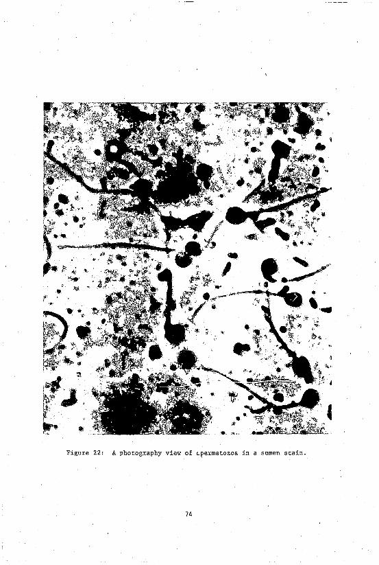
I"~
".
Figure 22: A photography view of Lpermatozoa in a semen stain.
74
j' :~ ."
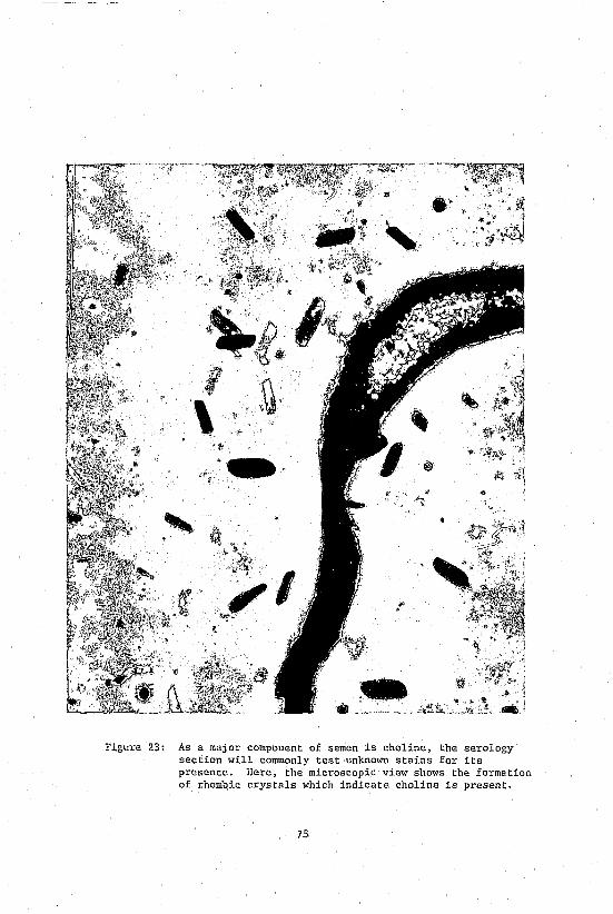
@ ~ 'iii
"I
,,! • " :~
Figure 23: As a major component of semen is choline, the serology section will commonly test unlmown stains for its presence. Here, the microscopic view shows the formation of rhombic crystals ~hich indicate choline is present.
75
ii. Absorption-inhibition techniques can detect the presence of these substances in body fluids and their stains.
b. Certain isoenzymes can be detected in some body fluids where they are present in large quantities. The demonstration of these depends on the amount of stain present, the age and nature of the stain, and the conditions under which the staln was stored.
These enzymes include PGH, PGD, ESD, end PEPA systems.
4. New Developments
a. Anti-P30: An immunological test was developed to detect a specific seminal protein P-30. This protein is specific to seminal plasma and not found in other body fluids, organs, or vagi~al material.
b. Serum protein markers: Gm, KID and Tf. Serum protein markers have been found in human seminal fluid. These markers can be detected by serologic~l or electrophoretic methods.
c. Sperm diaphorase: DIA is an isoenzyme in sperm cells. This system has potential v~lue in individualization of semen.
D. Documents
1. Documents: Any written, printed, or typed material is COnsidered e document. If the origin is unknown or the authenticity of the document is in doubt, the article is considered a "questioned document."
2. Types of document examination
a. Handw~iting comparisnns: After sufficient handwriting standards are either requested or collected, certain characteristics of the handwriting in each are looked for and carefully compared (See Figure 24).
h. Comparison of writing materials: Types of pen, inks, paper, and mechanical devices are determined and compared according to physical and chemical properties.
c. Determination of alterations: These include erasures, additions, deletions, obliterations, and eliminations.
d. Determination of COmmon origin or "Authorship": Examination and comparison may determine the manufacturer of inks, papers, and identiftcation of the mechanical device producing the marks.
76

e. Reconstructions: Charred or indented writing can be "raised" using various techniques. Matching of torn edges of the questioned document with another sample found at the scene, on the victim, or in the possession of the suspect may also be included in this type of examination.
3. Laboratory analysis of documents
a. Analysis of writing materials: Various chemical, microscopical, and instrumental techniques are employed for analysis of the '''riting instruments, ink, and paper.
b. Handwriting analysis: Class and individual characteristics of the questioned document and a known standard are analyzed and compared.
c. Typewriting analysis: Questioned typewritings can be compared with a known standard to detel'line the possible style, manufacturers, and possible individual source.
d. Alterations: Any change in the original writing on a document can be examined by (1) microscopic examination; (2) infrared microscopy and photography, and (3) ultraviolet photoghaphy techniques for alteration. (See Figures 25, 26, 27 and 28).
e. Printing and photocopying: These examinations are similar to handwriting or typewriting analysis. Through careful analysis, identification of the class and individual characteristics is carried out. Photocopies show marks due to damage to the glass or drum, as well as other unique markings; since many photocopied documents may be made from part o'f the original it becomes more difficult to examine these types of evidence.
f. Indented writing: Impressions are sometimes left on a surface underlying the one upon which the writing occurred. Special techniques, such as oblique lighting, iodine fuming, etc., are employed when this type of evidence occurs (see Figure 29).
g. Charred documents: If a document is partially destroyed through burning, the writing can sometimes be made visible by the use of IR light and photography (see Figure 30).
h. Determination of document age: Determination of age is carried out by analysis of the components of the documents such as ink and paper.
77

QUESTIONED
KNOWN WRITING;
; ... ~~ ~ ,--~l
_' • .~ 1*"
Figure 24: A comparison chart showing an identification of handwriting suitable for court use.
78
f ,
I .. J

Figure 25: This photograph, taken with infrared film, shows that the Jai-alai ticket on the right has been altered.
79
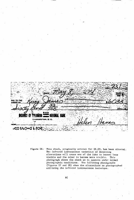
> "'Ill .'
'1IStIEJ oi'm.BII::;1Di1R .: \"JAS"'NGT,ON. 0; Co ', .
• *4V"'.. ,.1'_, _" '
6li:O 5"Omri'~20it~~'~~J.:';':':'> . , , ' "~~-~~,,,-.
Figure 26: This check, originally written for $6.03, has been altered. The infrared luminescence technique of detecting alterations will cause one of the inks to become less visible and the other to become more visible. This photograph shows the check as it appears under normal photographic conditions. The following photographs (Figures 27 and 28) show the alterations as photographed utilizing the infrared luminescence technique.
80
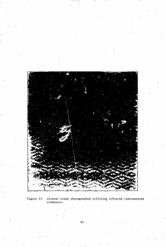
Figure 27: Altered check photographed utilizing infrared luminescence technique.
81
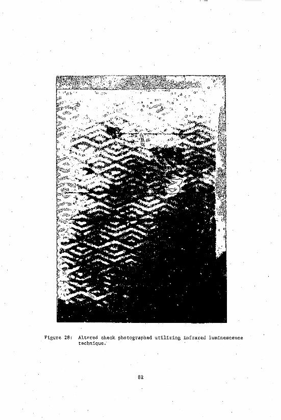
Figure 28: Altered check photographed utilizing infrared luminescence technique.
82
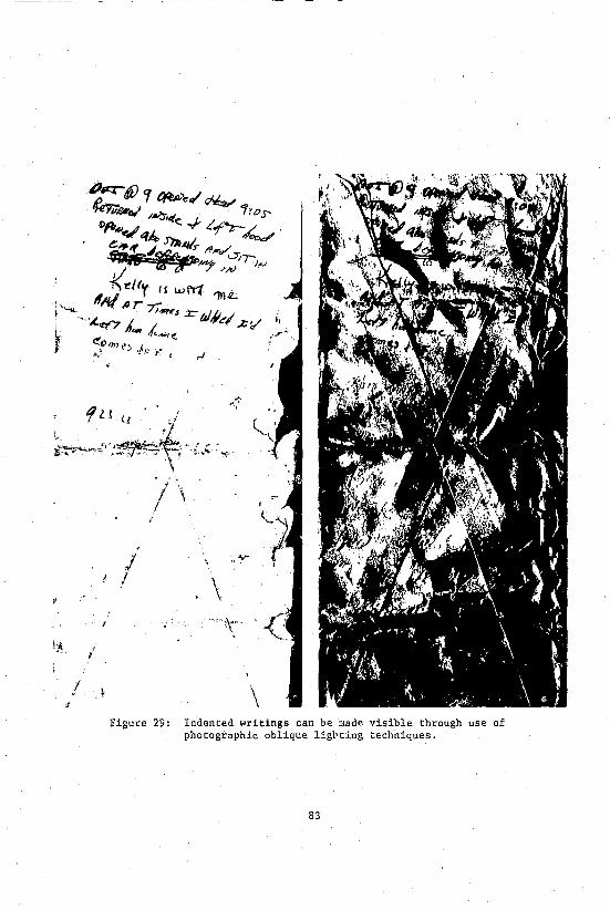
!;.* {
I
.I t
~ .;:. / \ I I
/ ! / \
\ Figure 29: Indented writings can be made visible through use of
photographic oblique ligbting techniques.
83

Figure 30: Legibility of the contents of burned or charred documents is a problem often encountered by the investigator. In many cases, the Document Section of the laboratory is capable of restoring the text of the message.
84
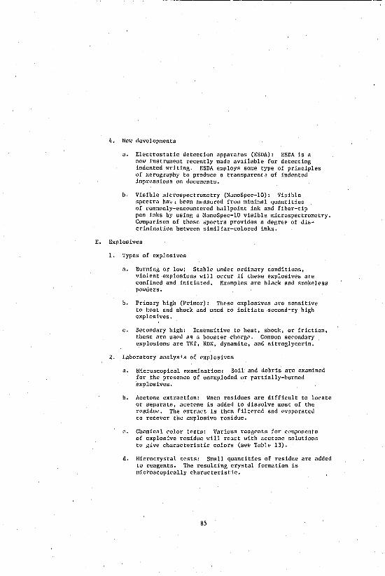
4. New developments
a. Electrostatic detection apparatus (ESDA): ESDA is a new instrument recently made available for detecting indented writing. ESDA employs some type of principles of xerography to produc .. a transparen(, of indented impressions on documents.
b. Visible mjcrospectrometry (NanoSpec-IO): Visible spectra ha\·, been measured from minimal quantities of com:nonly-encountered ballpoint ink and fiber-tip pen inks by using a NanoSpec-IO visible microspectrometry. Comparison of these spectra provides a degree of discrimination between similiar-colored inks.
E. Explosives
1. Types of explosives
n. Burning or low: Stable violent explosions will confined and initiated. powders.
under ordinary conditions, occur 1f these explosives are
Examples are black and smokeless
b. Primary high (Primer): These explosives are sensitive to heat and shock and used to initiate second·~y high explosives.
c. Secondary high: Ins~nsitive to heat, shock, or friction, these are used as a booster charge. Common secondary explosions are TNf, RDX, dynamite, and nitroglycerin.
2. Laboratory analys's of explosives
a. Microscopical examination: Soil and debris are examined for the presence of unexploded or rartia1ly-burned explosives.
b. Acetone extraction: When residues are difficult to locate or separate, acetone is added to dissolve most of the residue. The extract is then filtered and evaporated to recover the explosive residue.
c. Chemical color tests: Various reagents for components of explosive residue will react with acetone solutions to give characteristic colors (see Table 13).
d. Microcrystal tests: Sma1l quantities of residue are added to reagents. The resulting crystal formation is microscopically characteristic.
85
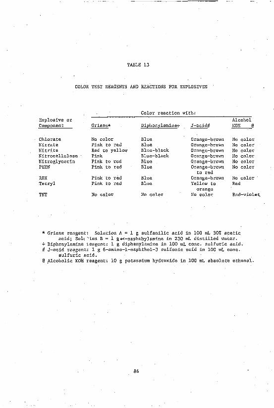
TABLE 13
COLOR TEST REAGENTS AND REACTIONS FOR EXPLOSIVES
Color reaction with: Explosive or Alcohol Component Griess* Diphonylamine+ J-acidll KOH @
Chlorate No color Blue Orange-brown No color Nitrate Pink to red Blue Orange-brown No color Nitrite Red to yellow Blue-black Orange-brown No color Nitrocellulose Pink Blue-black Orange-brown No color Nitroglycerin Pink to red Blue Orange-brown No color PETN Pink to red Blue Orange-brown No color
to red RDX Pink to red Blue Orange-brown No color Tetryl Pink to red Blue Yellow to Red
orange TNT No color No color No color Red-violet,
* Griess reagent: Solution A = 1 g sulfanilic acid in 100 mL 30% acetic acid; Soh "ion B = 1 go<-naphthylamine in 230 mL distilled water.
+ Diphenylamine .eagent: 1 g diphenylamine in 100 mL cone. sulfuric acid. II J-acid reagent: 1 g 6-amino-l-naphthol-3 sulfonic acid in 100 mL cone.
sulfuric acid. @ Alcoholic KOH reagent: 10 g potassium hydroxide in 100 mL absolute ethanol.
86

e. Thin layer chromatography: Acetone solutions of the residue are spotted on a plate, developed, and compared ~o known explosives.
3. Instrumental analysis
Detection of ~arious components using instrumental techniques has been extremely successful.
n. Organic components: Infrared spectra of a residue can be compared to know standards to identify an explosive according to the types of organic components present.
b. Ino,ganic components: Atomic absorption, atomic emission, and NAA aid in the detection of inorganic substances. Use of the scanning electron microscope is also possible.
4. New developments
n. Explosive tagging program: Some time ago, ATF instituted an explosive tagging program. Color-coded 8 layer taggant particles were added to the explosive material for tracing the origin of explosives. However, this program has been terminated.
b. New instrumental procedures: Several new instrumental procedures utilize HPLC (High Performance Liquid Chromatography) to detect various expl' ., '.
F. Fingerprints
1. Basic patterns
There arc eight basic fingerprint patterns (see Figures 32 and 33).
a. Loop: The ridges flow inward and then recurve in the direction of the origin. A single delta-shaped divergence must be present in front of the recurving ridges.
i. Radial loop: Ridges flow from the recurve toward the radius or thumb side of the hand; approKimately 5% of all fingerprint patterns.
ii. Ulnar loop: Friction ridges flow from and recurve tOI,ard the ulna or little finger side of the hand, approximately 60% of all fingerprint patterns.
b. Arch: Ridges enter on one side of the impression and tend to flow out the other side with a rise in the center.
1. Plain arch: Ridges enter, wave or rise, and exit smoothly.
87

Figure 31: Gas chromatograms of gasoline. The upper curve is a chromatogram of a known gasoline sample. The lower curve is a chromatogram of a burned gasoline sample recovered from a piece of wood. Note the loss of early emerging peaks (low boilers) in the burned sample. A special high-resolution column known as a capillary column v!as used for these chromatograms. Note the large number of peaks and their sharpness.
88

Plain Whorl Central Pocket Loop
Accidental Double Loop
Figure 32: Fingerprint patterns.
89
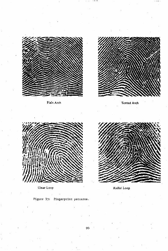
Plain Arch Tented Arch
Ulnar Loop Radial Loop
Figure 33' F' , ~ngerprint patterns,
90

ii. Tented arch: Ridges in the center thrust upward to give an appearance similar to a tent. Both types of arches combined Comprise approximately 6% of all fingerprint patterns.
c. Whorl: At least two delta-shaped divergences Bre present with recurving ridges in front of each.
1. Plain whorl: One or more ridges form a complete revolution around the center.
ii. Central pocket whorl: Some ridges form a loop pattern which recurves and surrounds a central whorl.
iii. Double loop: Two separate loops are present, which sometimes surround each other.
iv. Accidental: Any pattern which does not conform to previously described patterns.
v. Whorls compose approximately 29% of all fingerprint patterns.
2. Types of fingerprints
a. Inked prints: Ridge impressions are taken by inking an individual's finger or palm.
b. Visible prints: Ridge impressions which are caused by the transfer of a medium such as paint, blood, ink, or the like.
c. Plastic prints: Ridge impressions which are found in ~oft material such as putty, wax, clay, or the like.
d. Latent prints: Ridge impressions which aloe caused by the transfer of natural body secretions. These are among the most common types of fingerprint evidence found at a crime scene and must be processed for visual comparison. The composition of these secretions may be found in Figure 34, following.
3. Laboratory examination of latent prints
a. Prints on nonporous sUl:£aces: ImpreSSions on objects such as metal, plastic, glass, tile. and the like are easily processed at the scene.
i. Powder dusting: A powder of contrasting color to the surface being dusted is chosen. This is extremely important for obtaining good prints.
91
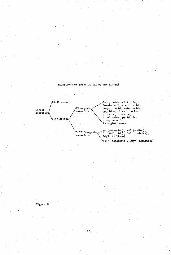
SECRETIONS OF SHEAT GLANDS OF THE FINGERS
/
98.5% water ~fatty acids and lipids. formic acid, acetic acid,
L <1% organic butyric acid. amino acids. S:~~:~ion materials pepti~es. albumin. other
\ prote~nsJ vitamins,
1.5% solids riboflavins. pyridoxin, urea, ammonia isoagglutinogens
Figure 34
K+ (potassium). Na+ (sodium). 0.5% inorganic\Cl_ (chloride). Ca'+ (calcium). materials P043- (sulfate)
504= (phosphate). C03= (carbonate)
92

ii. Hagna-brush method: Fine steel particles ~re used as powder and a magnet as a brush.
h. Prints on porous) ab50~bent surfaces: Impressions on paper, cardboard, leather, wood, etc. must be chemically treated and must be developed in the laboratory. Some common chemical methods are:
i. Iodine fuming: Vapor from warmed iodine crystals reacts with the oils deposited, yielding a yellowbrown print. These must be photographed immediately or fixed chemically.
ii. Ninhydrin: Reagent is sprayed on the medium and reacts with amino acids frvm body secretions, giving a violet color.
iii. Silv .. ( nitrate: A dark image is produced when the silver nitrate solution reacts with salts in the latent print after exposure to light.
iv. Fluorescent reagents: Fluorescamine and o-Phthalaldehyde react almost instantaneously with amines from body secretions, yielding highly fluorescent patterns. These reagents are useful on multi-colored surfaces.
c. Prints of human skin
i. Paper transfer method: Hard-surfaced paper and Polaroid ® coating stick are used to lift the print.
ii. Iodine-Silver method: Iodine-fumed prints are exposed to a tin polished silver plate, turning it black at ridge locations.
4. New developments
Various techniques using advanceu technology have been employed with some success.
a. Argon laser: In the proper optical setup, various components of body secretions fluoresce and may be photographed. This technique is non-destructive, but expensive, and requires specialized equipment.
b. X-RRy detection: Prints are dusted with lead powder, producing distinct images on photographic film when exposed to X-rays. This is useful on many objects and on skin.
93

c. Vacuum coating: A fine vapor of metal is developed in a vacuum and deposits on the print. Prints on paper, fabrics, tind plastics have been processed in this manner.
d. Super glue method: This process relies on the fumes of cyanocrylic glue chemically reacting with the water and amino acid molecules.
Table 14 summarizes various methods used for visualizing latent fingerprints.
5. Decomposed body
The laboratory is equipped to make identifications of fingerprints from decomposed bodies. Silicone or glycerine may be injected into the fingers; in some cases, the skin is removed, mounted on a glass slide and photographed from the back of the skin thus making the patterns visible. Ultimately, identifications are made in many cases.
6. Comparison of fingerprints
a. Identification and comparison of fingerprints is based on the recognition of general patterns and ridge characteristics (sea Figure 35).
b. A 1973 International Association for Identification (I.A.I.) study has concluded that no valid basis exists for requiring a predetermined minimum number of friction ridge characteristics which must be present in two impressions in order to establish positive identity.
c. In the August Identification News 1979, the I.A.I. reported the passage of Resolution VII which states in part:
"Wherdas the delegates of the International Association for Identification, assembled in their 64th annual conference in Phoenix, Arizona, August 2, 1979, state unanimously that friction ridge identifications are positive, and officially oppose any testimony or reporting of possible, probable or likely friction ridge identifi~ation."
7. Fingerprint classification system (See Table 15)
a. Henry System: The most common in use in the United States today. It is a ten-finger classification system that is easily retrieved frcm files.
94

TABLE 14
~mTHODS OF VISUALIZING LATENT FINGERPRINTS
Physical Powder dusting
Oblique lighting and photography
Laser
X-ray
Vacuum coating
Chemical Iodine fuming
Ninhydrin
Silver nitrate
Fluorescamine, phthalaldehyde, dansyl, chloride
Nitric acid, hydrofluoric acid
Super Glue (cyanoacrylate)
PRINCIPLE
Adherence of inert material to fingerprint residues
Natural residues of fingerprints
Luminescent material in fingerprint residue
Adherence to lead powder to fingerprint residues
Adherence of gold, silver, or cadmium to fingerprint residues
Chemical interaction of iodine with fatty acids and lipid in residues
Chemical interaction with amino acids, peptides, and proteins of residue
Chemical interaction with chloride in residue
Chemical interaction with amino acids in residue
Chemical reaction with surfaces without destroying residues
Chemical reaction with amino acid & water molecule
95
SURFACES TO HIIICII APPLICABLE
Smooth, nonporous surfaces, such as metals, glass, plastics, tile, and finished woods.
Smooth and nonreflective surfaces.
Smooth, nonporous or slightly porous surfaces, such as plastic, and paper (nonfluorescent)
Smooth, nonporous, and slightly porous surfaces, such as human skin.
Smooth surfaces, such as plastic films, polycthylc and paper.
Smooth surfaces, such as paper, human skin
Paper, cardboard
Paper
Paper, multicolored absorbent surfaces (noofluoreRccnt)
Glnss, cartrid~c cases
Plastic, metal glass, cloth, etc.

2
LA TENT FINGERPRINT INKED FINGERPRltH
4 4 5
7
11 10
Figure 35: Fingerprint comparison charts showing the points of identification which indicate a positive match.
96

Classification
Primary
Secondary
Subsecondary
Final
Major
Key
TABLE 15
FINGERPRINT CLASSIFICATION
17 Lflolu ION ~W OIl 10
17 L 10/ulIOM 19~OII 10
17 L 10 ulIOMi 19 W OIl 10
17 L 10 U Imln 19 w OII~
17 MI0 U 10M U19 H on 10
fi7lL 10 U IOH U 19 W OIl 10
97
Description
Obtained through the summation of the value of the whorls as they appear in the various fingers
The type or pattern appearing in the index fingers
The value of the ridge counts of loops or tracing of whorls of index, middle, and ring fingers.
The ridge count of loops of little fingers
The value of t.he ridge counts of loops or. tracing of ,qhorls of thumb
The ridge count of the first loop appearing in fingers other than the little finger

b. NCIC: Is a system used by the National Crime Information Center. This method is a modified Henry System written in a format that yields quicker retriaval from computers.
c. American Systenl: A modified Henry System in use in the New York Identification and Intelligence System.
d. Canadian System: Also an adaption and modification of the Henry System.
e. Vucetich System: The predominant system in use in South America.
f. Finder System: This computerized system was developed by the FBI based on the presence of certain small details on the inked print. The electronics of the method peri,lit computor enhancement of the print for more clarity of minutiae. This is particularly important in classifying poor quality inked prints for ultimate storage within the computer.
g. Battley System: A system for storage and retrieval of single fingerprints.
G. Firearms Evidence
1. Major components of firearms
a. Barrel
i. Rifled: A series of spiral grooves cut inside metal tube, leaving raised areas called "lands"; these make characteristic markings for identification.
ii. Smooth-bored: No lands or grooves present.
iii. Caliber: Gun barrel diameter measure between opposite lands.
b. Firing mechanism: The firing pin, breechlock, ejector, and extractor make characteristic marks on cartridge casings which can be used for identification and comparison.
c. Ammunition
i. Projectile: Bullet of lead/alloy, pellets, or slugs.
ii. Jacket: Some bullets are either completely or rartially encased in a harder metal.
98
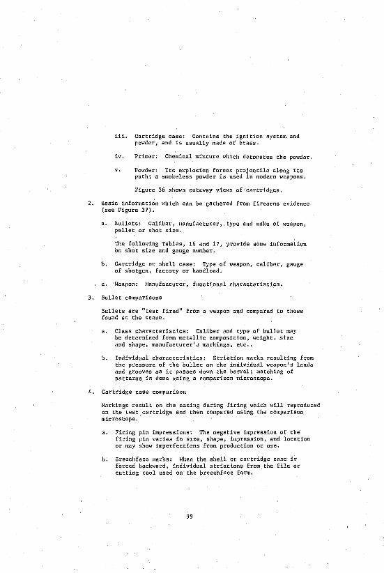
iii. Cartridge case: Contains the ignition system and powder, and is usually made of brass.
iv. Primer: Chemical mixture which detonates the powder.
v. PONder: Its explosion forces projectile along its path; a smokeless powder is used in moderrt weapons.
Figure 36 shows cutaway views of cartridges.
2. Basic information which can be gathered from firearms evidence (see Figure 37).
a. Bullets: Caliber, manufacturer, type and make of weapon, pellet or shot size.
The following Tables, 16 and 17, provide some information on shot size and gauge number.
b. Cartridge or shell case: Type of weapon, caliber, gauge of shotgun, factory or handload.
c. Weapon: Hanufacturer, functional characteristics.
3. Bullet comparisons
Bullets are "test fired" from a weapon and compared to those found at the scene.
a. Class characteristics: Caliber and type of bullet may be determined from metallic composition, weight, size and shape, manufacturer'J markings, etc .•
b. Individual characteristics: Striation marks resulting from the pressure of the bullet on the individual weapon's lands and grooves as it passes down the barrel; matching of patterns is done uSing a comparison microscope.
4. Cartridge case comparison
Harkings result on the casing during firing which will reproduced on the test cartridge and then compared using the comparison microscope.
a. Firing pin impressions: The negative impression of the firing pin varies in S1ze, shape, impression, and location or may show imperfections from production or use.
b. Breechface marks: When the shell or cartridge case is forced backward, individual striations from the file or cutting tool used on the breechface form.
99

Center Fire Rifle Canridge
Anvil
"Kleanbore" priming mhcture (in rim)
Shotgun Shell
Figure 36: Cutaway views of cartridges.
100
Rim Fire Cartridge
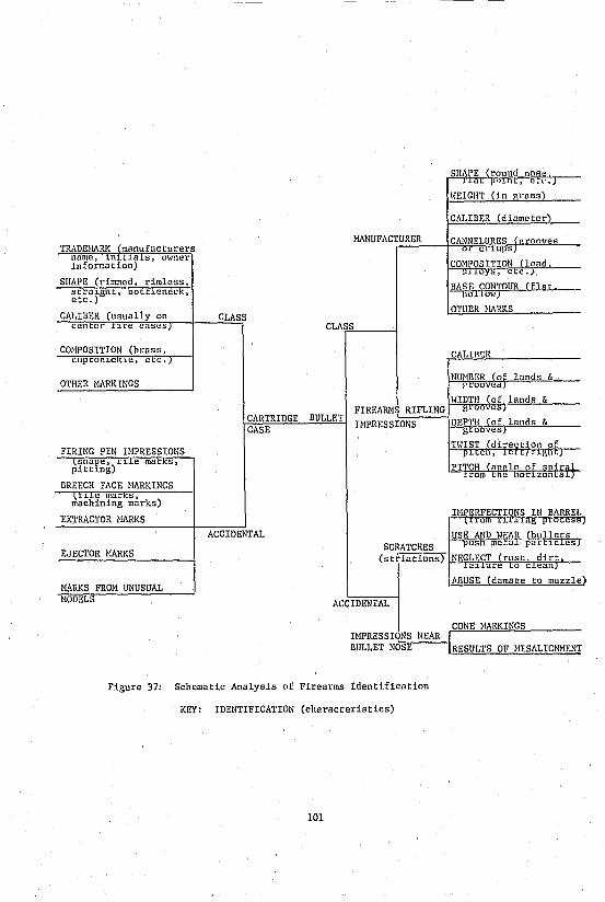
TRADEHARK (manufacturers name, 101-1a s, owner information)
SHAPE (rimmed. rimless. scral.ght. bottleneck, etc.)
CO}WOSITION (brass, cupronlCt e, e-c.
OTHER HARKINGS
EX'fRACTOR HARKS
EJECTOR HARKS
MARKS FROH UNUSUAL HODELS
CLASS
COHPOSITION lead . oys, e 'C.
BAS E CONTOUR (f1 a r. hollml1)
OTHER HARKS
CLAS,#SL-_-I
CARTRIDGE BULLET CASE
CALlJl~R
NUHBER a lands & r,rOQves
14lDTH (of lands & FIREARH~_R:.:I:::F;.:L:.:I:.:N:...G-1 grooves} UIPRESSIONS J!D!.!!.E<;;P~T¥~~ovA!~!1i~~l,-"al!Jn!!!d.!ls_&!:!.-__
ACCIDENTAL USE AND WEAR (bullets pus 1 mecdr piii:b.cIes) SCRATCHES
(striations) NEGLECT (rust, dirt, ra11ure to clean)
JlBUSE
ACCIDENTAL
CONE HARKINGS I}WRESSIONS NEAR BULLET NOSE RESULTS OF HISALIGNHENT
Figure 37: Schematic Analysis of Firearms Identification
KEY: IDENTIFICATION (characteristics)
101
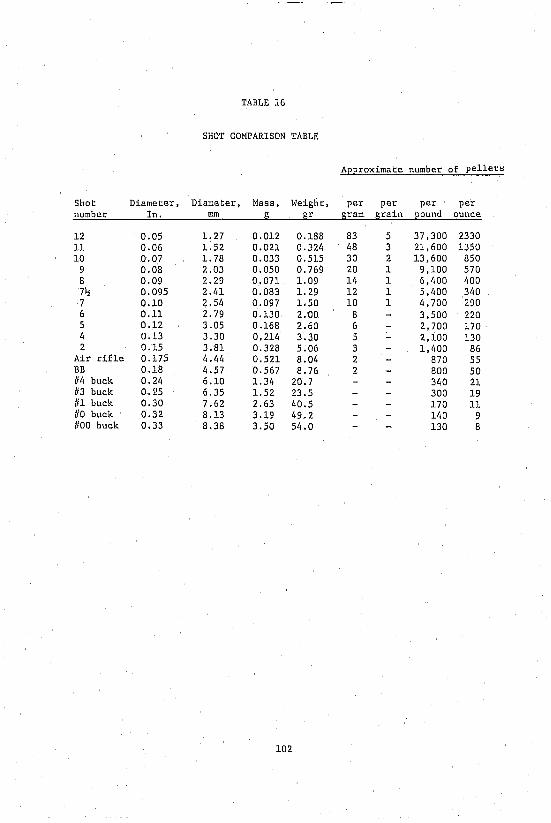
TABLE 16
SHOT COMPARISON TABLE
Approximate number of pellet!;
Shot Diameter, Diameter, Mass, Weight, per per per per number In. mm !l gr gram grain Eound ounce
12 0.05 1. 27 0.012 0.188 83 5 37,300 2330 11 0.06 1.52 0.021 0.32q q8 3 21,600 1350 10 0.07 1. 78 0.033 0.515 30 2 13,600 850
9 0.08 2.03 0.050 0.769 20 1 9,100 570 8 0.09 2.29 0.071 1.09 14 1 6,qOO 400 7~ 0.095 2.41 0.083 1. 29 12 1 5,400 340 7 0.10 2.54 0.097 1.50 10 1 4,700 290 6 0.11 2.79 0.l30 2.00 8 3,500 220 5 0.12 3.05 0.168 2.60 6 2,700 170 4 0.13 3.30 0.214 3.30 5 2,100 l30 2 0.15 3.81 0.328 5.06 3 1,400 86
Air rifle 0.175 4.44 0.521 8.04 2 870 55 BB 0.18 4.57 0.567 8.76 2 800 50 /14 buck 0.2q 6.10 1.34 20.7 340 21 113 buck 0.l.!5 6.35 1.52 23.5 300 19 /11 buck 0.30 7.62 2.63 40.5 170 11 /10 buck 0.32 8.13 3.19 49.2 140 9 /100 buck 0.33 8.38 3.50 5q.0 130 8
102
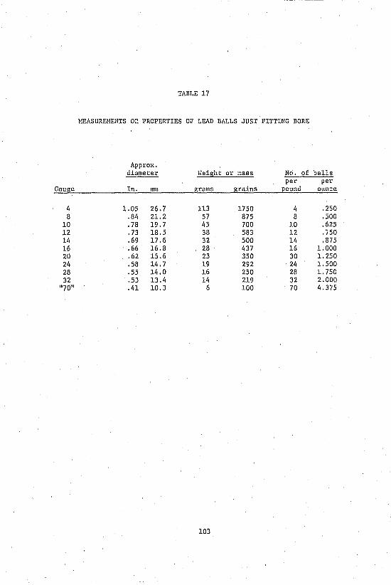
TABLE 17
HEASUREHENTS O~ PROPERTIES OF LEAD BALLS JUST FITTING BORE
Approx. diameter Weight or mass No. of balls
per per Gauge In. mm grams grains pound ounce
4 1.05 26.7 113 1750 4 .250 8 .84 21. 2 57 875 8 .500
10 .78 19.7 45 700 10 .625 12 .73 18.5 38 583 12 . 'i50 14 .69 17.6 32 500 14 .875 16 .66 16.8 28 437 16 1.000 20 .62 15.6 23 350 30 1.250 24 .58 14.7 19 292 24 1.500 28 .55 14.0 16 250 28 1. 750 32 .53 13.4 14 219 32 2.000
"70" .41 10.3 6 100 70 4.375
103
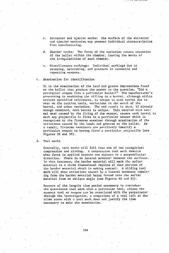
c. Extractor and ejector marks: The surface of the extractor and ejector mechanism may possess individual characteristics from manufacturing.
d. Chamber marks: The force of the explosion causes expansion of the bullet within the chamber, leaving the marks of the irregularities of each chamber.
e. Hiscellaneous markings: Individual markings due to scraping, scratching, and pressure in automatic and repeating t~eapons.
4. Examination for identification
It is the examination of the land and groove impressions found on the bullet that produce the answer to the question, "Did a particular weapon fire a particular bullet?" The manufacturer's processing in machining thE' rifling in a barrel, ,,1 though t~itldn certain specified tolerances, is unique to each barrel due to wear on the cutting tools, variations in the metal of thb barrel, and other variables. The end result is that, if closely enough examined, each barrel is uni.que. This coupled with normal wear caused by the firing of the m~apon, causes each barrel to mark any projectile it fires in a particular manner which is recognized by the firearms examiner through examination of the striations caused by the lands and grooves on the bullet. As a result, firearms examiners can positively identify a particular weapon as having fired a particular projectile (see Figures 38 and 39).
5. Tool marks
Generally, 1:001 marks \Yill fall into one of ttvO categories: compression and sliding. A compression tool mark results when force is applied bet\Yeen two objects in a perpendicular direction. There is no lateral movemen~ between the surfaces. In this instance, the harder material will mark th~ softer material in a three dimensional replica of that portion of the harder material which is making contact. A sliding tool mark will show striations caused by a lateral movement resulting from the harder material being forced into th~ softer material from an oblique angle (see Figures 40 and 41).
Because of the lengthy time period necessary to reproduce the questioned tool mark \Yith a particular tool, unless the suspect tool or tveapon can be associated with the perpetrator through the investigation, a comparison of a tool left at the crime scene with a tool mark does not justify the time necessary to make the examination.
104

Figure 38: A view through the comparison microscope showing that the breech face markings on the two shell casings shown here were made by the same source.
105

Figure 39: A positive match is indicated b~tween two bullets, as seen under the comparison microscope. Left side is a questioned bullet, right hand side is a known test bullet.
106

Figure 40: A tool mark comparison between a forced door frame striker plate-and a screw driver found in the possession of a suspected burglar, linked him to the crime.
107
Figure 41: Tool mark comparisons can also be made through use of the comparison microscope, as illustrated inthis photograph. It shows that the suspected screw driver (in Figure 40) did in. fact make the striations on the striker plate.
108
H. Gunshot residu~
1. Source of gunshot residue
When a gun has been fired, gunshot residue can originate from:
a. Primer: Primer consists of 4 basic components.
i. Initiating explosive - Lead styphnate
ii. Oxidizing agent - Barium Nitrate, Barium Peroxide, Lead Nitrate, Lead Peroxide.
iii. Fuel: Antimony sulfide, Calcium Silicide
iv. Sensitizing agent: Tetracene
b. Propellant, powder
1. Black Powder - 75% potassium nitrate - 15% sulfur - 10% charcoal
ii. Smokeless Powder - Nitrocellulose (single bas~)
c. Lubrica'lts
- Nitrocellulose & Nitroglycerin (double hase)
d. Hetal from projectile, bullet, jacket, and casing metals: Lead, Copper - trace ~lementsJ Zinc, Antimony, Arsenic, Bismuth, Chromium, etc.
e. Gun barrel
2. Laboratory analysis of gunshot residue
a. Microscopical analysis: Examination for the presence of gun powder panicles, smudges, aud burns around a bullet hole or in swabbings of the hands.
b. Chemical tests for nitrates and nitrites.
i. Reagents react with these components to give a colored pattern. This is useful for showing the distribution of residue on clothing or in ps'raffin lifts.
ii. Commonly oc~urring substances such as cigarette smoke, urine, and fertilizer also react "ith these reagents.
109

c. Detection of trace elements: Barium, antimony, bismuth, and lead concentrations can be determined. These are usually in low concentrations on the hands of an individual who has not recently fired a weapon.
1. Hicrochemical tests: These tests may be highly specific, but requires larger quantities of metal than instrumental methods.
ii. Neutron activation: EKtrcmely sensitive, NAA can detect very low concentrations of metals.
iii. Atomic absorption: Also detects low concentrations of metals in the samples. Neither NAA or AA gives information about patterns of gunshot residue deposits. Levels of trace metals in "hand blanks" must be determined for proper interpretation of AA results.
3. Pattern analysis
Pattern analysis is useful in reconstructing shooting events, especially in distance estimation. Interpretations are dependent upon the weapon used, type of ammunition, load, etc. (see Figure 42).
a. Close range: Residues are deposited around the bullet hole with black shot and smoke. The pattern is small and dense.
h. Hedium range: (l~ - 3 feet) Scattered gunshot residue is present without black deposits. The pattern spreads out as the distance increases.
c. Long range: Powder residue is usually not found.
4. New developments
a. Paraffin test: It is also referred to as "dermal nitrate test". The GSR (Gun Shot Residue) particles are identified by reaction of nitrate or nitrite with diphenylamine. This test yields positive reaction with fertilizer, tobacco, urine, soil, and many other compounds. It is currently considered unreliable for GSR tes ting.
b. SEH - EDX: The GSR particles Scanning Electron Hicroscope. analyzed by X-ray. A finding barium, and antimony confirms
110
can be identified by The particles are further
of the elements lead, that the particles are GSR.
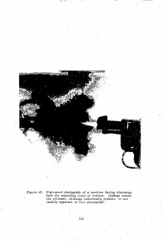
Figure 42: High-speed photograph of a revolver during discharge. Note the expanding cloud of residue. Leakage around the cylinder, although undoubtedly present, is not readily apparent in this photograph.
111
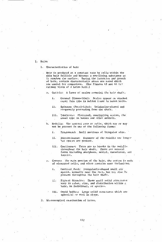
1. Huirs
lIair is produced at u constant rate by cells ",ithin the skin hair follicle and hecomes a non-livin~ substance as it reaches the surface. During the [ormation and growth of hair, certain characteristic areas are noted "hieh arc useful fl1r comparison. (See Fi~ures 43 and 44 fc~ cutut>ay vie"s uf a human hair.)
a. Cuticle, A layer of scales covering the hair ,;haft.
1. Coronal (Crown-like), Scale,; appear as "tacked cups; this type is seldom found in human hairs.
ii. Spj.nuQus (Petal-like): Triangular-shaped and frequently protruding from the shaft.
iii. Imbricat',: Flattened, overlapping scales, the usual type in humans and other animals.
b. Medulla: The central core of cells, which may C'r may not be present in one of the fo11o"ing forms,
1. Fragmented; Small sectiuus of irregular size.
ii. Discontinuous: S~gments of the medulla are longer hut spaces are present.
iii. Continuous, There an' no breaks in the medulla throughout the hair shaft. There are sevt'raJ forms including amorphous, s"rial, vacuolate,d, ,md lattice.
c. CortLl<' Th .. main purtion of the hair, the ,'orte" i,; made of elongated cells, ond often .:ontain~ many inclusions ..
1. Cortical Fusi, Irregularly-shaped small air spaL:es t normally near the root, but may .1151".' h0 prescnt throughout the hair shaft.
ii. Pigmot'lt Granules, Tll"so small solid ,;trudures vary in ,,,,lur, Bize, and distribution "Uhin a hair, an ittdividual, I".'r sp(~Cie5~
iii. Ovoid bodies: Large sl)lld structures "hieh :;r" spberical or ov.l1 in slnpe.
2. ~li<'Toscopical examination nf hairs.
112
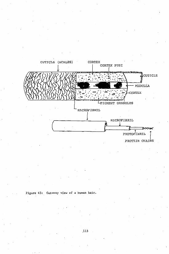
CUTICLE (SCALES) CORTEX
CLE
MACROFIBRIL
1 MICROFIBRIL
(~ __ ~t ~! l=l' i~~ PROTOFIBRIL r
PROTEIN CHAINS
Figure 43: Cutaway view of a human hair •
. ll3
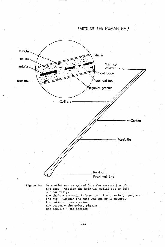
cuticle
medulla
proximal
Cuticle
PARTS OF THE HUMAN HAIR
Tip or distal end
ovoid body
cortical fusi
H-------- Medulla
-f---------- Root or Proximal End
Figure 44: Data which can be gained from the examination of •.• the root - "hether the hair was pulled out or fell out naturally. the shaft - cosmetic information, i.e., curled, dyed, etc. the tip ., whether the hair was cut or is natural the cuticle - the species the cortex - the color, pigment the medulla - the species
114
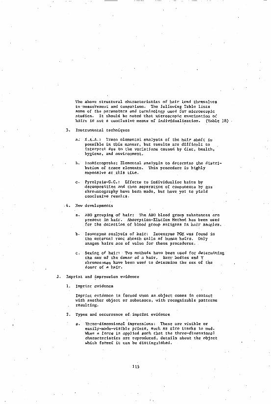
The above structural characteristics of hair lend themselves to measurement and comparison. The following Table lists some of the parameters and terminology used for microscopic studies. It should be noted that microscopic examination of hairs is not a conclusive means of individualization. (Table 18)
3. Instrumental techniques
a. N.A.A.: Trace elemental analysis of the hair shaft is possible in this manner, but results are difficult to interpret due to the variations caused by diet, health, hygiene, and environment.
b. IonMicroprobe: Elemental analy&1s to determine the distribution of trace elements. This procedure is highly expensive at this tiwe.
c. Pyrolysis-G.C.: Efforts to individualize hairs by decomposition and then separation of components by gas chro/Jatography have been made, but have yet to yield conclusive results.
4. New developments
a. ABO grouping of hair: The ABO blood group substances are present in hair. Absorption-Elution Method has been used for the detection of blood group antigens in hair samples.
b. Isoenzyme analysis of hair: Isoenzyme PGM was found in the external root sheath cells of human hairs. Only anagen hairs are of value for these procedures.
c. Sexing of hair: Two methods have been used for determining the sex of the donor of a hair. Barr bodies and Y chromosomes have been used to determine the sex of the donor of a hair.
J. Imprint and impression evidence
1. Imprint evidence
Imprint evidence is formed when an object comes in contact with another object or substance, with recognizable patterns resulting.
2. Types and occurrence of imprint evidence
a. Three-dimensional impressions: These are visible or easily-made-visible prints, such as tire tracks in mud. When a force is applied such that the three-dimensional characteristics are reproduced, details about the object which formed it can be distinguished.
115

TABLE 18
ANALYSIS FACTORS IN THE COHPARISON OF HAIR
Scale pattern:
Hedulla:
Hedulla pattern:
Diameter:
Length:
Color:
Reflectivity:
Tip:
Root:
Special configuration:
Cross section:
Pigment:
Cortical fusi:
Cuticle:
Cortical pigment:
Cosmetic treatment:
Damage:
Race:
Body area:
Special characteristics:
ABO grouping:
PGM phenotype:
coronal - spinous - imbricate
absent - fragmentary - discontinuous - continuous
uniserial - multiserial - vacuolated - lattice -amorphous
constant - vary - range
fragment - segment
white - blonde - light brown - brown - dark brown -gray - black - red
opaque - translucent - transparent - clear
cut - broken - split - pointed - round
normal - stretched - absent - bulbous - germ -follicular
straight - curved - wavy - curly - kinky
polygonal - flat - oval - round
absent - granular - chain - clump - dense - opaque
absent - few - bunched - abundant
ragged - serrated - looped - layered - narrow - wide
central - periphery - oneside - root
bleached - dyed - length of treatment - curled
cut - crushed - broken - burned
Caucasian - Negroid - Hongoloid - Hixed
head - pubic - body hair - beard
disease
A, B
1, 2-1, 2
116
b. Two-dimensional impressions: A flat residue deposited after an object or individual passes through, a fine colored substance often shows the detail of that object. Shoe impressions on window-sills or chairs and bloody fabric impressions are examples to two-dimensional impressions.
c. Occurrence of imprints: Imprints may be found at any scene where soft or transferable materials are present. They are often useful in reconstruction and in giving some information about the criminal. The most commonly encountered types of imprint evidence are footprints and tire tracks.
3. Laboratory analysis of imprint evidence
Determination of class and individual characteristics of an impression allows for identification of the type of object which made the il1'pression and, at times, the manufacturer. The comparison of imprints with known samples or other imprints is also performed.
a. Class characteristics: General structural properties such as size, shape, pattern, and design are noted. If the imprint is a footprint, for example, the sbe should be determined using standard footwear scales. Manufacturers often produce characteristic patterns and logos on their footwear.
b. Individual characteristics: Individual characteristics are those which are specific for a particular object.
i. Wear, damage, irregularities, and other accidental marks are unique to a particular article.
ii. The exact location, size, and shape of each individual mark is documented.
c. Comparison of impreSSions With knowns
i. Class characteristics of the known and the imp'I'e'ssion are compared. If the two demonstrate common class characteristics, a positive statement may be made about the similarity of the articles.
ii. If individual characteristics of the known and the imprint agree, it can be concluded that the knOlffi produced the impression. As with other typea of physical evidence comparisons, no exact number ~f points of matching has been identified as ne('essary for a match.
117

iii. Hhen making comparisons with casts, the shrinkage of casting 111llterials must be considered. Charts and formulae exist to eid in these determinations.
iv. The conditions present when the impression was made should be reproduced as much as pOflsible when making a print or impression of the known for comparison.
K. Pattern evidence
1. Pattern evidence may contain both class and individual characterisLics and can thus form the basis for identification, for individualization, and for reconstruction.
2. There are many types of pattern evidence that can be found at a crime scene; some are obvious, others are more subtle. Some examples are:
3.
a. Blood patterns
b. Glass fracture patterns
c. Projectile-Trajectory patterns
d. Gunshot residue patterns
e. Footprints and tire track patterns
f. Furniture disarrangement patterns
g. Tool mark patterns
h. H. O. patterns
i. Skid marks patterns
j. Fire burning patterns
Bloodstain patterns
The patterns obtained when blood hits a surface is dependent upon the nature of the surface, its texture, absorbancy, etc. Care must be taken when interpreting patterns to consider the effects of the surface.
Blood patterns "lay provide information about the circumstances of the crime, victim, or suspect.
a. Shape of the stain gives information about the distance and angle from which the blood is dropped on a non-absorbant surfdce (see Figures 45 and 46).
118

• e 3//
• e 6"
o t~
Figure 45: The height from which a drop of blood has fallen can be estimated from the diameter of the stain and the texture of the target surface.
119
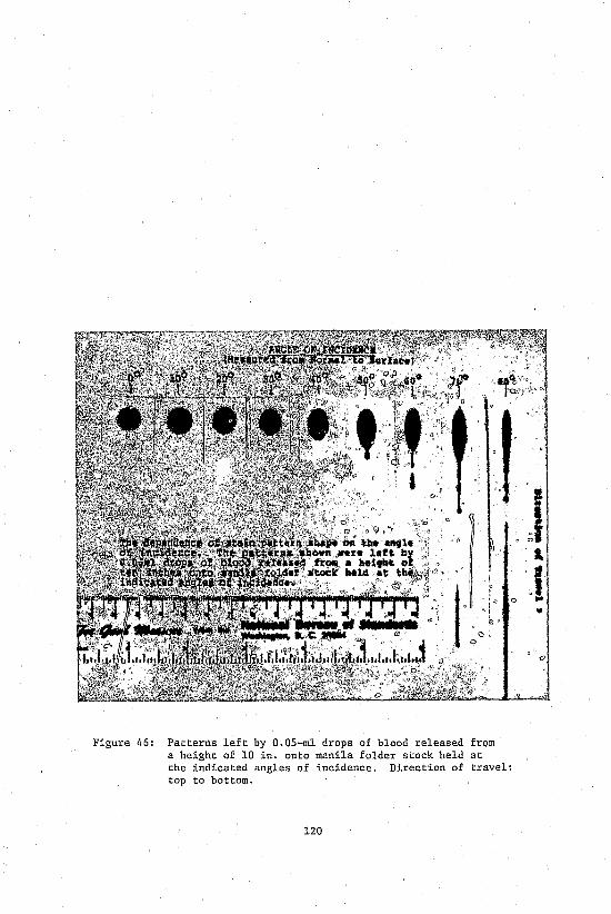
Figure 46: Patterns left by O.OS-ml drops of blood released from a height of 10 in. onto manila folder stock held at the indicated angles of incidence. Direction of travel: top to bottom.
120
~I .. J ... •
i. Circular: Indicates a shorr distance (less than 12 inches).
ii. Jagged: Indicates a falling distance greater than 12 inches.
iii. Oplatter: Indicates a distance greater than 3 feet.
iv. Bludgeon-shaped: Indicates the angle of impact with sr.lall spotn trailing in the direction of the fall.
b. The size of the pattern and droplets gives information about th" speed and force of formation, keeping in mind the effects of surface and distance on the pattern.
c.
i. Low velocity: Small force, droplets form with little scattering.
i1. Hedium velocity: Intermediate force, ragged edges on the droplet and some secondary scattering of blood.
iii. High velocity: Great force, extensive scattering, very fine droplets form around and point toward the central area of initial impact.
Other types of blond patternR
i. Radial spatter patterns from blows
ii. Arc patterns fr~m swinging weapons
iii. Patterns from artery spurts
iv. Trail patterns
v. Contact and transfer patterns
vi. Patterns from Shooting
vii. Patterns of droplets
4. Glass fracture patterns
a. Types of fractures: When force is applied to glass, there is an initial stretching of the surface on the opposite side to the applied force. Once the elastic limits of the glass have been exceeded, radial cracks form looking much li-k,e the spokes of a wheel. As the force continues to build, concentric cracks begin to form on the same side as the applied force since this surface of the glass has now been placed under tension.
121

b.
Thus, every glass break is a failure of the surface under tension 'dth the break following a bending away from the direction of the applied force. The surface opposite the force under tension breaks first. Note that the concentric cracks being circular in shape have as their c"nter the original point of impact (see Figure 47).
Generally, from glass fracture patterns, the forensic scientist could make the following six (6) types of determination:
i. Radial fractures vs concentrit.! fractures.
1i. Determine the point of impact.
iii. Deterlline the entrance and the exit.
Iv. Determine the velocity of projectile.
v. Determine the sequence of impacts.
vi. Determine the nature of impact force.
Glass fracture examination
i. Determining the direction of force (see Figure 48)
(a) Crater at the paint of impact - a projectile passing through or striking but not penetrating through the glass will leave a cone-shaped crater with the smallest diameter on the same side as the applied force and the larger diameter on the side opposite the applied force.
(b) Examination of the edge surfaces of the various fractures will also yield information on the direction of farce. The "Three R Rule" can be of assistance in this problem. It states "Radial cracks will have Right angles on the Reverse side of applied {orce." If the observer looks at the edges of a radial crack, shaped lines will be seen with one end of the "c" being at a 90· angle to the surface opposite the applied force. The converse of this rule is true when looking at the edges of concentric fractures due to the physics involved in the actual fracture, i.e., concentric cracks will have right angles on the side of the force.
(c) Sequence of multiple fractures - the order of occurence can be determined by observation of
122

Figure 47: Reconstruction of the sequence of bullet holes in window glass. The sequence of shots fired through a pane of glass is usually obvious from an examination of the fracture lines. When this information is combined with that from a determination of direction, it should be possible to tell which of t,~o shooters on either side of the glass fired first.
123
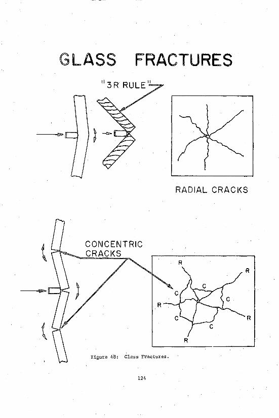
G LASS FRACTURES
RADIAL CRACKS
CONCENTRIC CRACKS
R R
R
R
R
Figure 48: Glass Fractures.
124
the fracture lines. Once the initial fracture has been made, subsequent fractures will terminate at the original fracture lines thus, observation of these fractures endings will provide sequence information.
Cd) "Blow Back Effect" - small particles of glass will be sprayed back toward the direction of applied force in any glass fracture. It is these particles that may be found in the hair and garments of the person breaking the glass and, as such, should be compared to the glass standards taken from the crime scene.
ii. Di.rection of travel of the break: Examination of the edge of a broken piece of glass shows curved, rib-shaped lines which are perpendicular to the glass surface I~here the crack began and nearly parallel at the end of the crack. This can be used to determine whether the break was inward or outward--assuming thaL it is known which side of the glass Ims in/out originally.
ii Sequence of breaks: Radial lines which end at the junction with a second radial line fracture must have been formed by a later force.
iv. Individualization: A physical match proving that two pieces of glass fit together exactly is the only conclusive individualization possible.
L. Photography section
1. In addition to processing all film shot by members of the Division of State Police, the Photography Section also has the ability to exercise various techniques to visually enhance physical evidence and, in many instances, to make comparisons by other laboratory sections possible. These techniques include.
a. Transmitted lighting: Where light is passed through the object being photographed, and contrasting detail on the face of the object becomes visible. Examples would include glass and documents (see Figures 49 and 50).
b. Vertical illun;ination: l-lhere it becomes necessary to light the interior of small tubular-type objects without shadows falling on the interior. An example would be the interior of a firearm barrel.
125

Figure 49: Note the difference that lighting can make when photographing a translucent object. The object in this photograph is lit from the front, while, in Figure 50, it is lit from behind.
126
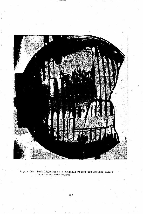
Figure 50: Back lighting is a suitable method for showing detail in a transl~cent object.
127
c. Infrared, infrared luminescence and ultraviolet photography: Very effective in detecting alterations on documents, and restoring obliterated \~riting and laundry marks (see Figures Sl and 52).
d. Tent lighting: Where it is necessary to photograph shiny or reflective objects without characteristic burnout caused by the light source. This technique will also remove the possibility of shadows appearing in target areas (see Figure 53).
2. The Forensic Science Laboratory Photography Section also provides services in the following specialized areas:
a. Aerial photographs
b. Forensic photographs
c. Photo eIllargement and enhancement
d. Specialized color photographs
e. Hug shot photographs
f. Photo training
H. Reconstruction
1. Types of reconstruction
There are two general types of reconstruction services currently provided by the Connecticut State Police Forensic Science Laboratory.
a. Accident reconstruction
i. Traffic accident reconstruction
ii. Other accidents
b. Crime reconstruction
2. Traffic Accident Reconstruction
The Traffic Accident Reconstruction Team utilizes the physical evidence and information produced by a collision of a motor vehicle with another vehicle, object, or person to reconstruct the events preceding and resulting from an accident.
Based upon scene photographs, line drawings, the condition of the vehicle involved, the statements of the investigating officers and witnesses, physical evidence resulting from the
128

Figure 51: This "copy" shot illustrates a handkerchief as it appears under normal photography. Utilizing ultra-violet light, the laundry mark becomes visible (Figur~ 52).
129

Figure 52: Laundry mark on handkerchief becomes visible under ultra-violet light.
130

accident. and the known data available. the Reconstruction Team may provide the following information regarding the accident:
a. Stopping distances determination
b. Homentum and speed determination
c. Vehicle function determination
d. Degree of damage estimation
e. Diagram and sketch assistance
f. Sequence of events determination
g. Accident scene analysiS
h. Time and distance analysis
N. Trace evidence
1. Trace evidence includes many types of materials which are deposited or transferred as a result of direct contact. The most commonly encountered trace evidence includes:
a. Fibers (, feathers
b. Glass (, soil
c. Food (, oils
d. Wood (, vegetation
e. Paint (, insulation
f. Hetals (, building materials
g. Plastics (, rubber
h. Oil (, grease
i. Pollens (, spores
j. Chemicals (, others
2. Types and classification of fiber and glass
a. Type of fiber evidence
132

1- Natural fibers
(a) animal fibers
(b) vegetable fibers
(c) mineral fibers
ii. Derived and regenerate fibers
iii. Synthetic fibers
3. E~amination of trace materials
a. Physical match: In larger samples, physical matchbg of two pieces of materia! may be possible. Physical matching can be achieved through a direct fit and match method, or an indirect pattern match method.
b. Microscopical e~amination: Color, te~ture, shape, pattern, layer structure, and surface striation can be compared with microscopical examination.
c. Hicrochemical tests: Various chemical reagents are available to solubility, color, or crystal tests.
d. Physical property determination: Physical characteristics such as hardness, melting point, density, ash formation, and tensile strength can be measured.
e. Poliarizing Microscopy: Various types of determination, such as birefringent, dispersion, e~tinction angle, optic sign, sign of elongation, and refractive indices can be made using the polarizing microscope.
f. Instrumental methods: Organic and inorganic composition of the trace evidence can be analyzed using IR spectroscopy, pyrolysis G.C., AA, NAA, X-ray, mass spectroscopy, and emission spectroscopy.
4. New developments
a. Ion Hicroprobe mass analyzer (HfrlA): This is a new and sensitive technique for elemental analysis. HfrlA can be used to determine the distribution of trace elements within a miscroscopic sample.
b. Hicroinfrared spectrophotometer (NANOSPEC/20-IR): Nano Spec 20-IR provides molecular analysis in areas, or of samples, as small as 20 X 20 urn. This technique can be used to determine the organic composition of trace sample (see Figure 54).
133

Figure 54: The microUV-visible spectrophotometer (NANOSPEC/10)
134
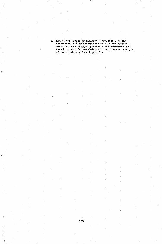
c. SEH-X-Ray~ Scanning Eleccron Nicroscope with the aCtachmen~ such as energy-dispersi>le X-ray spectrometel' or wave-length-dispersive X-ray sp<lctrometets have been used for morphological and elemental analysis of trace evidence (see Figure 55).
135
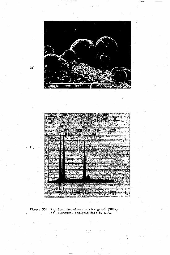
(~
(b)
Fig~re 55: (a) Scanning electron micrograph (900x) (b) Elemental analysis data by EDAX.
IJh