
IES 2010 EC II - IES Academy · India’s No 1 Engineering Service Examination-2010 IES Academy E &...
26
India’s No 1 Engineering Service Examination-2010 IES Academy E & T Engineering Paper-II www.iesacademy.com E-mail: [email protected] Page 1 25, 1 st Floor, Jia Sarai, Near IIT. New Delhi-16 Ph: 011-26537570, 9810958290 Question Paper of Engineering Service Examination 2010 Electronics and Telecommunication Engineering Paper-II Objective 1. Consider the following statements: When compared with a bridge rectifier, a centre-tapped full wave rectifier: 1. Has larger transformer utilization factor. 2. Can be used for floating output terminals i.e. no input terminal is grounded. 3. Needs two diodes instead of four. 4. Needs diodes of a lower PIV rating. Which of the above statements are correct? (a) 1 and 2 only (b) 1, 2, 3 and 4 (c) 3 only (d) 3 and 4 only 2. A linear time-invariant system initially at rest, when subjected to a unit- step input, gives a response y |t| = te –t , t > 0. The transfer function of the system is : (a) 2 1 (s 1) + (b) 2 1 s(s 1) + (c) 2 s (s 1) + (d) 1 s 1 + 3. The hexadecimal representation of 6578 is : (a) 1AFH (b) D78H (c) D71H (d) 32FH 4. A 13 bit PCM system performance is better than an 8 bit PCM system because : (a) Noise is lower and is proportional to reciprocal of bandwidth (b) Bandwidth is larger and detection is easier (c) Quantization noise is lesser other things being equal (d) Quantization noise is nearly zero since 2 13 levels are available
Transcript of IES 2010 EC II - IES Academy · India’s No 1 Engineering Service Examination-2010 IES Academy E &...

India’s No 1 Engineering Service Examination-2010 IES Academy E & T Engineering Paper-II
www.iesacademy.com E-mail: [email protected] Page 1
25, 1st Floor, Jia Sarai, Near IIT. New Delhi-16 Ph: 011-26537570, 9810958290
Question Paper of Engineering Service Examination 2010 Electronics and
Telecommunication Engineering
Paper-II Objective
1. Consider the following statements: When compared with a bridge rectifier, a centre-tapped full wave
rectifier: 1. Has larger transformer utilization factor. 2. Can be used for floating output terminals i.e. no input terminal is grounded. 3. Needs two diodes instead of four. 4. Needs diodes of a lower PIV rating. Which of the above statements are correct? (a) 1 and 2 only (b) 1, 2, 3 and 4 (c) 3 only (d) 3 and 4 only
2. A linear time-invariant system initially at rest, when subjected to a unit-step input, gives a response y |t| = te–t, t > 0. The transfer function of the system is :
(a) 21
(s 1)+ (b) 2
1s(s 1)+
(c) 2s
(s 1)+ (d) 1
s 1+
3. The hexadecimal representation of 6578 is : (a) 1AFH (b) D78H (c) D71H (d) 32FH
4. A 13 bit PCM system performance is better than an 8 bit PCM system because : (a) Noise is lower and is proportional to reciprocal of bandwidth (b) Bandwidth is larger and detection is easier (c) Quantization noise is lesser other things being equal (d) Quantization noise is nearly zero since 213 levels are available

India’s No 1 Engineering Service Examination-2010 IES Academy E & T Engineering Paper-II
www.iesacademy.com E-mail: [email protected] Page 2
25, 1st Floor, Jia Sarai, Near IIT. New Delhi-16 Ph: 011-26537570, 9810958290
5. Match List I with List II and select the correct answer using the code given below the lists : List I List II
(Device) (Application) A. Transferred electron devices 1. Microwave amplifier B. Two-cavity Klystron 2. Microwave oscillator C. PIN diode 3. Microwave low power measurement D. Bolometer 4. Modulator Code :
A B C D (a) 3 1 4 2 (b) 2 1 4 3 (c) 3 4 1 2 (d) 2 4 1 3
6. The default parameter-passing mechanism in C-programming language is: (a) Call by reference (b) Call as random (c) Call by value (d) Call by value result
7. Consider the function F(s) = 25
s(s 3s 2)+ + where F(s) is Laplace transform
of function f(t). The initial value of f(t) is :
(a) 5 (b) 52
(c) 53
(d) 0
8. The data type defined by user is : (a) Built-in data type (b) Abstract data type (c) Homogeneous data type (d) Real data type
9. Insertion of a record in a circularly linked list involves the modification of : (a) 4 pointers (b) 3 pointers (c) 2 pointers (d) 1 pointer
10. The spectrum of a band pass signal spans from 20 kHz to 30 kHz. The signal can be recovered ideally from the sampled values when the sampling rate is at least : (a) 20 kHz (b) 60 kHz (c) 50 kHz (d) 40 kHz
11. Match List I with List II and select the correct answer using the code given below the lists : List I List II A. Rectangular waveguide 1. Plane of polarization B. Waveguide twists 2. Waveguide tuner

India’s No 1 Engineering Service Examination-2010 IES Academy E & T Engineering Paper-II
www.iesacademy.com E-mail: [email protected] Page 3
25, 1st Floor, Jia Sarai, Near IIT. New Delhi-16 Ph: 011-26537570, 9810958290
C. Slotted section 3. TE10 mode D. Stub screws 4. VSWR measurements Code : A B C D (a) 2 4 1 3 (b) 3 4 1 2 (c) 2 1 4 3 (d) 3 1 4 2
12.
230 V50 Hz 12 V VdcC
100 Fμ
–
+D (ideal)
The output Vdc from the above circuit is :
(a) 12 2 (b) 12π
(c) 24π
(d) 122
13. Which of the following data structure is used by a compiler to manage information about variables and their attributes? (a) Abstract syntax tree (b) Linked list (c) Parse table (d) Symbol table
14. A transistor works in three regions : 1. Cut-off 2. Active 3. Saturation While used as switch in digital logic gates, the regions it works in are : (a) 1 and 2 only (b) 2 and 3 only (c) 1 and 3 only (d) 1, 2 and 3
15. The number of edges in a regular graph of degree D and N vertices is equal to :
(a) ND (b) ND2
(c) N + D (d) ND
16. The Boolean expression A B C A B C A B C ABC+ + + + + + + + + reduces to :
India’s No 1 Engineering Service Examination-2010 IES Academy E & T Engineering Paper-II
www.iesacademy.com E-mail: [email protected] Page 4
25, 1st Floor, Jia Sarai, Near IIT. New Delhi-16 Ph: 011-26537570, 9810958290
(a) A (b) B (c) C (d) A + B + C
17. A single bus structure is primarily found in : (a) Main frames (b) Mini and micro computers (c) Super computers (d) High performance machines
18. In a unity feedback control system with G(s) = 24
s 0 4s+ ⋅ when subjected
to unit step input, it is required that system response should be settled within 2% tolerance band; the system setting time is (a) 1 sec (b) 2 sec (c) 10 sec (d) 20 sec
19. The ability to halt the CPU temporarily and use this interval of time to send information on buses is called : (a) Cycle stealing (b) Vectoring an interrupt (c) Polling (d) Direct memory access
20. A rectifier (without filter) with fundamental ripple frequency equal to twice the mains frequency, has ripple factor of 0⋅482 and power conversion efficiency equal to 81⋅2%. The rectifier is: 1. Bridge rectifier 2. Full-wave (non bridge) rectifier 3. Half-wave rectifier. Which of these are correct? (a) 2 and 3 only (b) 2 only (c) 1 and 2 only (d) 1, 2 and 3
21. Consider the following : 1. Compilers 2. Design 3. Evaluation 4. Instruction set architecture Which of these are included in the present definition of computer architecture to design a full computer system ? (a) 1, 2 and 3 (b) 1, 3 and 4 (c) 2, 3 and 4 (d) 1, 2, 3 and 4
22. The Nyquist rate for the signal x(t) = 2 cos (2000 πt), cos (5000 πt) is : (a) 7 kHz (b) 5 kHz (c) 14 kHz (d) 10 kHz
23. Given that main memory access time is 1200 ns and Cache access time is 100 ns; the average memory access time is not to exceed 120 ns. The hit ratio for the Cache must be at least : (a) 90% (b) 98% (c) 80% (d) 75%

India’s No 1 Engineering Service Examination-2010 IES Academy E & T Engineering Paper-II
www.iesacademy.com E-mail: [email protected] Page 5
25, 1st Floor, Jia Sarai, Near IIT. New Delhi-16 Ph: 011-26537570, 9810958290
24.
R(s) y(s)+ + +– 3 2
3s + 1
d(s)
The transfer function from d(s) to y(s). is :
(a) 23s 7+
(b) 23s 1+
(c) 63s 7+
(d) 23s 6+
25. An IO
processor controls the flow of information between :
(a) Cache memory and IO
devices
(b) Main memory and IO
devices
(c) Two IO
devices
(d) Cache and main memory
26. R(s) y(s)+
– 4 3s + 1
10s + 10
The characteristic equation of the above closed-loop system is : (a) s2 + 11s + 10 = 0 (b) s2 + 11s + 130 = 0 (c) s2 + 10s + 120 = 0 (d) s2 + 10s + 12 = 0
27. The standard SOP expression for Boolean expression AB AC BC+ + is : (a) ABC ABC ABC ABC+ + + (b) ABC ABC ABC+ + (c) ABC ABC ABC+ + (d) ABC ABC ABC+ +
28. The complement of the expression Y = ABC ABC ABC ABC+ + + is : (a) (A B) (A C)+ + (b) (A B) (A C)+ + (c) (A B) (A C)+ + (d) (A B) (A C)+ +

India’s No 1 Engineering Service Examination-2010 IES Academy E & T Engineering Paper-II
www.iesacademy.com E-mail: [email protected] Page 6
25, 1st Floor, Jia Sarai, Near IIT. New Delhi-16 Ph: 011-26537570, 9810958290
29. Which one of the following has the shortest access time? (a) NMOS EPROM (b) NMOS RAM (c) CNOS RAM (d) Bipolar static RAM
30. The main disadvantage of using coaxial cable for microwave signals is its: (a) Low selectivity (b) Low distortion (c) High attenuation (d) High sensitivity
31. If the gain of the system is reduced to zero value, the roots of the system in the s-plane : (a) Coincide with zeros (b) Move away from the zeros (c) Move away from the poles (d) Coincide with the poles
32. The figure of merit of a logic family is given by the product of : (a) Gain and bandwidth (b) Propagation delay time and power dissipation (c) Fan-out and propagation delay time (d) Noise margin and power dissipation
33. In NOR-NOR configuration, the minimum number of NOR gates needed to implement the switching function X XY XYZ+ + is : (a) 5 (b) 3 (c) 2 (d) 0
34. The addition of open loop zero pulls the root-loci towards : (a) The left and therefore system becomes more stable (b) The right and therefore system becomes unstable (c) Imaginary axis and therefore system becomes marginally stable (d) The left and therefore system becomes unstable
35. Match List I with List II and select the correct answer using the code given below the lists : List I List II A. HTL 1. High fan-out B. CMOS 2. Highest speed of operation C. I2L 3. High noise immunity D. ECL 4. Lowest product of power and delay Code : A B C D (a) 3 4 1 2 (b) 2 1 4 3 (c) 3 1 4 2 (d) 2 4 1 3
36. On receiving an interrupt from an I ,O
device, the CPU :
(a) Halts for a predetermined time. (b) Branches off to the interrupt service routine after completion of the current
instruction (c) Branches off to the interrupt service routine immediately (d) Hands over control of address bus and data bus to the interrupting device

India’s No 1 Engineering Service Examination-2010 IES Academy E & T Engineering Paper-II
www.iesacademy.com E-mail: [email protected] Page 7
25, 1st Floor, Jia Sarai, Near IIT. New Delhi-16 Ph: 011-26537570, 9810958290
37. Consider the following statements with regard to a PLL : 1. The ‘capture range’ of a PLL primarily depends upon the slope of transition
band edge of the low-pass filter. 2. The ‘lock range’ is not affected by the slope of transition band of the low-pass
filter. Which of the above statements is/are correct? (a) Both 1 and 2 (b) 1 only (c) 2 only (d) Neither 1 nor 2
38. In microprocessor based systems DMA facility is required to increase the speed of data transfer between the : (a) Microprocessor and the I/O devices (b) Microprocessor and the memory (c) Memory and the I/O devices (d) Memory and the reliability system
39. If x(t) is of finite duration and is absolutely integrable, then the ‘region of convergence’ is : (a) Entire s plane (b) From σ = –1 to σ = + ∞ (c) From σ = +1 to σ = –∞ (d) Entire right half plane
40. The quantization noise of a PCM system depends on : (a) Number of quantization levels (b) Step-size (c) Both step-size and number of quantization levels (d) Sampling rate
41. Match List I with List II and select the correct answer using the code given below the lists : List I List II A. Pipelined ALU 1. RISC B. Simpler compiler 2. CISC C. Separate data and instruction caches 3. Mixed RISC-CISC D. Lesser cycles per instruction Code : A B C D (a) 3 2 3 1 (b) 1 2 3 3 (c) 3 3 2 1 (d) 3 3 3 1
42.
P3 P4
P1 P2
Inputside
Outputside

India’s No 1 Engineering Service Examination-2010 IES Academy E & T Engineering Paper-II
www.iesacademy.com E-mail: [email protected] Page 8
25, 1st Floor, Jia Sarai, Near IIT. New Delhi-16 Ph: 011-26537570, 9810958290
For the above directional coupler a coupling factor in dB is :
(a) 110
4
P10 logP
(b) 110
2
P10 logP
(c) 210
4
P10 logP
(d) 110
3
P10 logP
43.
R
R
R
3 R
+
–
(4 – 2 cos t) voltsω
– 4 volts Vout
The output of the above OP-amp circuit is : (a) –0⋅75 volts (b) – 2 cos ωt volts (c) –8 cos ωt volts (d) 16 volts
44. A TDM system is to be designed to multiplex the following two signals : X1 = 5 cos (2000 πt) X2 = 2 cos (2000 πt) cos (3000 πt) The minimum sampling rate is :
(a) 4 kHz (b) 5 kHz (c) 10 kHz (d) 6 kHz
45. An example of a spooled device is : (a) A graphical display device (b) A line printer used to print the output of a number of jobs (c) A secondary storage devices in a virtual memory system (d) A terminal used to enter input data to a running program
46. Which one of the following is a Dirichlet condition?
(a) 1t
|x(t)|∞
< ∞∫
(b) Signal x(t) must have a finite number of maxima and minima in the expansion interval
(c) x(t) can have an infinite number of finite discontinuities in the expansion interval
(d) x2 (t) must be absolutely summable
47. Consider the following instructions of 8085 microprocessor : 1. MOV B, C 2. STA address 3. ORI byte The correct sequence in the decreasing order of their respective memory space requirement is : (a) 3, 2 and 1 (b) 1, 3 and 2

India’s No 1 Engineering Service Examination-2010 IES Academy E & T Engineering Paper-II
www.iesacademy.com E-mail: [email protected] Page 9
25, 1st Floor, Jia Sarai, Near IIT. New Delhi-16 Ph: 011-26537570, 9810958290
(c) 1, 2 and 3 (d) 2, 3 and 1
48. A DA
converter has 5 V full-scale output voltage and an accuracy of ± 0⋅2%.
The maximum error for any output voltage will be : (a) 5 mV (b) 10 mV (c) 20 mV (d) 1⋅0 mV
49. If the CALL instructions of 8085 in the main program is conditional then RETURN instruction in the subroutine can be : (a) Conditional (b) Conditional or unconditional (c) Can be determined by LDA instruction (d) Unconditional
50. A
C
E
B
D
F
X
The output X of the above logic circuit is : (a) AB + CD + EF (b) AB CD EF+ + (c) (A + B) ⋅ (C + D) ⋅ (E + F) (d) (A B) (C D) (E F)+ ⋅ + ⋅ +
51. The ‘Double minimum’ or the “width of minimum power” method is used in microwave measurements for the measurement of : (a) Velocity modulation (b) Frequency distortion (c) High V.S.W.R. (d) Low V.S.W.R.
52. Consider the following statements : 1. The lock range of a PLL is the difference between the highest and lowest
frequencies that the PLL can remain in lock onto. 2. The capture range of a PLL is the range of frequencies that the voltage
controlled oscillator of a PLL can produce. 3. PLL can be used to synchronize the horizontal and vertical oscillators of TV
receivers to incoming sync pulses. Which of the above statements is/are correct? (a) 1 only (b) 3 only (c) 1 and 3 only (d) 1, 2 and 3

India’s No 1 Engineering Service Examination-2010 IES Academy E & T Engineering Paper-II
www.iesacademy.com E-mail: [email protected] Page 10
25, 1st Floor, Jia Sarai, Near IIT. New Delhi-16 Ph: 011-26537570, 9810958290
53.
Z
A
I J
The circuit shown above is to be used to implement the function Z = f(A, B) = A B.+ The values of I and J are : (a) I = 0 and J = B (b) I = 1 and J = B (c) I = B and J = 1 (d) I = B and J = 0
54. In the Bode plot of a unity feedback control system, the value of phase angle of G (jω) is – 90° at the gain cross over frequency of the Bode plot, the phase margin of the system is : (a) – 180° (b) + 180° (c) – 90° (d) + 90°
55.
Y
A
B
C
The Boolean expression for the output of the above logic circuit is : (a) Y = AB AB C+ + (b) Y = AB AB C+ + (c) Y = A B C⊕ + (d) Y = AB C+
56. Match List I with List II and select the correct answer using the code given below the lists : List I List II A Cavity wave meter 1. Impedance measurements B. VSWR meter 2. Frequency measurements C. Bolometer 3. Antenna measurements D. Fraunhofer region 4. Microwave power measurements Code : A B C D (a) 3 1 4 2 (b) 2 1 4 3 (c) 3 4 1 2 (d) 2 4 1 3
57. The Nyquist plot of loop transfer function G(s) H(s) of a closed loop control system passes through the point (–1, j0) in the G(s) H(s) plane. The phase margin of the system is : (a) 0° (b) 45°
India’s No 1 Engineering Service Examination-2010 IES Academy E & T Engineering Paper-II
www.iesacademy.com E-mail: [email protected] Page 11
25, 1st Floor, Jia Sarai, Near IIT. New Delhi-16 Ph: 011-26537570, 9810958290
(c) 90° (d) 180°
58. When compared with an RS232C serial port, the USB (Universal Serial Bus) : (a) Supports a lower range of peripherals (b) Supports a faster transfer rate (c) Does not support ‘Hot plug-ability’ (d) Controller in PC can not detect the presence or absence of USB devices
59. A ROM is used to store the table for multiplication of two 8-bits unsigned integers. The size of the ROM required is : (a) 256 × 1 (b) 64k × 8 (c) 4k × 16 (d) 64k × 16
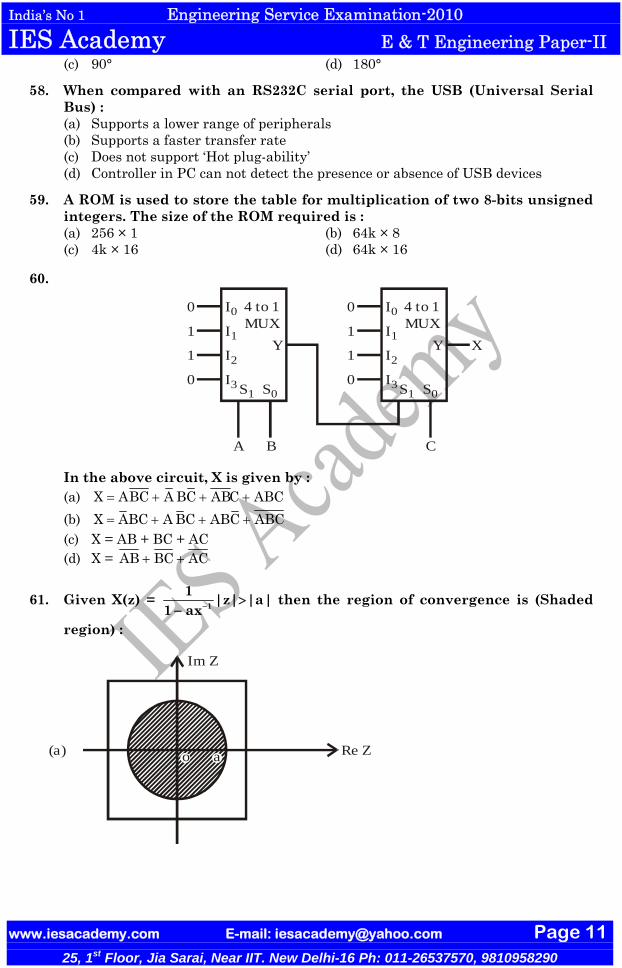
60.
I0 I0
I1 I1
I2 I2
I3 I3
0 0
1 1
1 1
0 0S1 S1S0 S0
4 to 1MUX
4 to 1MUX
A B C
Y Y X
In the above circuit, X is given by : (a) X ABC A BC ABC ABC= + + + (b) X ABC A BC ABC ABC= + + + (c) X = AB + BC + AC (d) X = AB BC AC+ +
61. Given X(z) = 11 |z| |a|
1 ax− >−
then the region of convergence is (Shaded
region) :
Im Z
Re Z(a) o a

India’s No 1 Engineering Service Examination-2010 IES Academy E & T Engineering Paper-II
www.iesacademy.com E-mail: [email protected] Page 12
25, 1st Floor, Jia Sarai, Near IIT. New Delhi-16 Ph: 011-26537570, 9810958290
Im Z
Re Z(b) o a
Im Z
Re Z(c) o a
Im Z
Re Z(d) o a
62. A ‘DMA’ transfer implies : (a) Direct transfer of data between memory and accumulator
(b) Direct transfer of data between memory and IO
devices without the use of μP
(c) Transfer of data exclusively within μP registers
(d) A fast transfer of data between μP and IO
devices
India’s No 1 Engineering Service Examination-2010 IES Academy E & T Engineering Paper-II
www.iesacademy.com E-mail: [email protected] Page 13
25, 1st Floor, Jia Sarai, Near IIT. New Delhi-16 Ph: 011-26537570, 9810958290
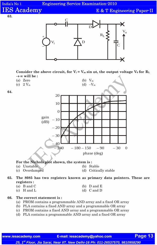
63.
+
–Vi
Vo
C
RL
D
D
C
Consider the above circuit, for Vi = Vm sin ωt, the output voltage V0 for RL
→ ∞ will be : (a) Zero (b) Vm
(c) 2 Vm (d) –Vm
64. 20
10
0
– 10
– 20
– 30
– 40– 240 – 180 – 150 – 90 – 30 0
phase (deg)
gain (dB)
For the Nichols plot shown, the system is : (a) Unstable (b) Stable (c) Overdamped (d) Critically stable
65. The 8085 has two registers known as primary data pointers. These are registers : (a) B and C (b) D and E (c) H and L (d) C and D
66. The correct statement is : (a) PROM contains a programmable AND array and a fixed OR array (b) PLA contains a fixed AND array and a programmable OR array (c) PROM contains a fixed AND array and a programmable OR array (d) PLA contains a programmable AND array and a fixed OR array

India’s No 1 Engineering Service Examination-2010 IES Academy E & T Engineering Paper-II
www.iesacademy.com E-mail: [email protected] Page 14
25, 1st Floor, Jia Sarai, Near IIT. New Delhi-16 Ph: 011-26537570, 9810958290
67.
Trigger0.01
Vout
6
7
25
3
4 8
+ VCC
R
555
The circuit shown above is a :
(a) Bi-stable multi-vibrator (b) Mono-stable mult-vibrator (c) Free running multi-vibrator (d) Ramp generator
68. Consider the following statements : 1. A multiplexer is analogous to a rotary switch. 2. A decoder is a combinational logic circuit that converts binary information
from ‘n’ input lines to a maximum of 2n distinct elements at the output. 3. The Boolean expression for the output different ‘D’ from a full subtractor is
exactly the same as the output sum ‘S’ from a full adder. Which of the above statements is/are correct? (a) 2 and 4 only (b) 4 only (c) 1 and 3 only (d) 1, 2 and 3
69. A ship to ship communication system is affected by fading. A useful solution which can be used is : (a) A more directional antenna (b) A broadband antenna (c) Use of frequency diversity (d) Use of space diversity
70. The impulse response h[n] of an LTI system is h[n] = u[n + 3] | u[n – 2] – 2u[n – 7]. Then the system is :
1. Stable 2. Casual 3. Unstable 4. Not causal. Which of these are correct? (a) 1 and 2 only (b) 2 and 3 only (c) 3 and 4 only (d) 1 and 4 only
71. For the experimental study of small microwave antennas, a free space environment with minimum interference by external objects, the facilities required are : (a) RF screens, VSWR meter, waveguide twist
India’s No 1 Engineering Service Examination-2010 IES Academy E & T Engineering Paper-II
www.iesacademy.com E-mail: [email protected] Page 15
25, 1st Floor, Jia Sarai, Near IIT. New Delhi-16 Ph: 011-26537570, 9810958290
(b) UHF screens, slotted waveguides, power meter (c) Anechoic chamber, Network analyzer, Pattern recorder (d) Dark room facility, Digital recorder, Bolometer
72. READY signal in 8085 is useful when the CPU communicates with : (a) A slow peripheral device (b) A fast peripheral device (c) A DMA controller chip (d) A PPl chip
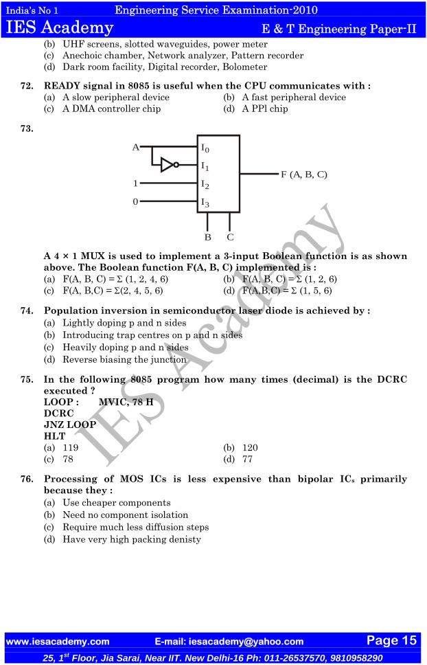
73.
I0
I1
I2
I3
A
1
0
B C
F (A, B, C)
A 4 × 1 MUX is used to implement a 3-input Boolean function is as shown above. The Boolean function F(A, B, C) implemented is : (a) F(A, B, C) = Σ (1, 2, 4, 6) (b) F(A, B, C) = Σ (1, 2, 6) (c) F(A, B,C) = Σ(2, 4, 5, 6) (d) F(A,B,C) = Σ (1, 5, 6)
74. Population inversion in semiconductor laser diode is achieved by : (a) Lightly doping p and n sides (b) Introducing trap centres on p and n sides (c) Heavily doping p and n sides (d) Reverse biasing the junction
75. In the following 8085 program how many times (decimal) is the DCRC executed ?
LOOP : MVIC, 78 H DCRC JNZ LOOP HLT
(a) 119 (b) 120 (c) 78 (d) 77
76. Processing of MOS ICs is less expensive than bipolar ICs primarily because they : (a) Use cheaper components (b) Need no component isolation (c) Require much less diffusion steps (d) Have very high packing denisty

India’s No 1 Engineering Service Examination-2010 IES Academy E & T Engineering Paper-II
www.iesacademy.com E-mail: [email protected] Page 16
25, 1st Floor, Jia Sarai, Near IIT. New Delhi-16 Ph: 011-26537570, 9810958290
77.
10 V
– 10 V
t
vi
6.6 kΩ
Ideal
Ideal
2.2 kΩ
2.2 kΩ
Vo +–
The correct waveform for output (Vo) for the above network is :
vo4.3 V
t(a)
vo
– 4.3 V
t(b)

India’s No 1 Engineering Service Examination-2010 IES Academy E & T Engineering Paper-II
www.iesacademy.com E-mail: [email protected] Page 17
25, 1st Floor, Jia Sarai, Near IIT. New Delhi-16 Ph: 011-26537570, 9810958290
5 V
– 5 V
t(c)
vo
t(d)
– 5 V
+ 5 V
78.
J
CLKCLK
K
J
K
Q
Q
The J-K flip-flop shown above is initially reset, so that Q = 0. If sequence of four clock pulses is then applied, with the J and K inputs as given in the figure , the resulting sequence of values that appear at the output Q starting with its initial state, is given by : (a) 01011 (b) 01010 (c) 00110 (d) 00101
79. A single instruction to clear the lower four bits of the accumulator in 8085 assembly language is : (a) XRl 0FH (b) ANl F0H (c) XRl F0H (d) ANl 0FH

India’s No 1 Engineering Service Examination-2010 IES Academy E & T Engineering Paper-II
www.iesacademy.com E-mail: [email protected] Page 18
25, 1st Floor, Jia Sarai, Near IIT. New Delhi-16 Ph: 011-26537570, 9810958290
80.
n 1
n
n
X Y Q0 0 10 1 Q
1 0 Q 11 1 0
+
An X-Y flip flop, whose characteristic table is given above is to be implemented using J-K flip flop. This can be done by making : (a) J = X, K = Y (b) J = X, K Y= (c) J Y, K X= = (d) J Y, K X= =
81. The Z-transform of – u (– n – 1) is :
(a) ZZ 1−
with |Z| > 1 (b) ZZ 1−
with 0 < |Z| < 1
(c) ZZ 1−
with |Z| = 1 (d) ZZ 1−
with |Z| = 0
82. The interface chip used for data transmission between 8086 and a 16 bit ADC is : (a) 8251 (b) 8253 (c) 8255 (d) 8259
83.
1 0 1 0Serial InputCLK
The shift register shown in the given figure is initially loaded with the bit pattern 1010. Subsequently the shift register is clocked, and with each clock pulse the pattern gets shifted by one bit position to the right. With each shift, the bit at the serial input is pushed to the msb position. After how many clock pulses will the content of the shift register become 1010 again? (a) 3 (b) 7 (c) 11 (d) 15

India’s No 1 Engineering Service Examination-2010 IES Academy E & T Engineering Paper-II
www.iesacademy.com E-mail: [email protected] Page 19
25, 1st Floor, Jia Sarai, Near IIT. New Delhi-16 Ph: 011-26537570, 9810958290
84. A microprocessor based system can perform many different functions, because : (a) Its operation is controlled by software (b) It is digital system (c) It uses a RAM (d) It can be controlled by input and output devices
85. QA
QB
QA
Q′B
Q′B
Q′A
QA
QA
Q′A
X J
J
K
K
Q
Q
B
A
CLK
Z
Analyze the sequential circuit shown above in figure. Assuming that initial state is 00, determine what input sequence would lead to state 11? (a) 1 – 1 (b) 1 – 0 (c) 0 – 0 (d) State 11 is unreachable
86. Which of the following instructions copies a byte of data into the accumulator from the memory address given in the instruction? (a) LDA address (b) LDAX B (c) LHLD address (d) STA address
87. The magnitude and phase of the transfer function G(s) = 1s 1+
at ω = 1 is :
(a) 0⋅707 and 45° (b) –3 dB and 0⋅78 rad (c) 0⋅707 and – 45° (d) 3 dB and – 90°
88. In a typical satellite communication system, which of the following could be the up-link and down-link frequencies respectively? (a) 40 GHz and 60 GHz (b) 60 GHz and 40 GHz (c) 6 GHz and 4 GHz (d) 4 GHz and 6 GHz

India’s No 1 Engineering Service Examination-2010 IES Academy E & T Engineering Paper-II
www.iesacademy.com E-mail: [email protected] Page 20
25, 1st Floor, Jia Sarai, Near IIT. New Delhi-16 Ph: 011-26537570, 9810958290
89. Which of the following is the response of a spring-mass-damper with under-damping?
0(a)
y(t)
Time
0(b)
y(t)
Time
0(c)
y(t)
Time
0(d)
y(t)
Time
90. The output data lines of microprocessors and memories are usually tristated, because : (a) More than one device can transmit information over the data bus by enabling
only one device at a time. (b) More than one device can transmit information over the data bus at the same
time (c) The data lines can be multiplexed for both input and output (d) It increases the speed of data transfers over the data bus

India’s No 1 Engineering Service Examination-2010 IES Academy E & T Engineering Paper-II
www.iesacademy.com E-mail: [email protected] Page 21
25, 1st Floor, Jia Sarai, Near IIT. New Delhi-16 Ph: 011-26537570, 9810958290
91.
D1D0
CLKCLK
Q1Q0
For the circuit shown, the counter state (Q1, Q0) follows the sequence : (a) 00, 01, 10, 11, 00 …. (b) 00, 01, 10, 00, 01 …. (c) 00, 01, 11, 00, 01 …. (d) 00, 10, 11, 00, 10 ….
92. From the point of view of stability and response speed of a closed loop system, the appropriate range for the value of damping ratio lies between: (a) 0 to 0⋅2 (b) 0⋅4 to 0⋅7 (c) 0⋅8 to 1⋅0 (d) 1⋅1 to 1⋅5
93.
A15
A9
A8
A7
A6
A5
A4
A3
A2
A1
A0
A14A13A12A11A10
CS
1 KBMemory
chip
Consider a memory chip with 1024 bytes storage connected to a 8085 chip address lines (or any microprocessor with 16 address lines) as above. What is the range of memory address?
India’s No 1 Engineering Service Examination-2010 IES Academy E & T Engineering Paper-II
www.iesacademy.com E-mail: [email protected] Page 22
25, 1st Floor, Jia Sarai, Near IIT. New Delhi-16 Ph: 011-26537570, 9810958290
(a) 0000 H to 03 FFH (b) 1000 H TO 13 FFH (c) F000 H to F3FFH (d) 0000 H to FFFFH
94. The output stage of a transponder onboard a satellite has a maximum power output of 10 watts. However, it is not operated at the maximum power output in order to : (a) Conserve the available limited battery power (b) Reduce noise due to devices (c) Avoid intermodulation distortion (d) Avoid heating up of the satellite beyond a pre set value
95. The purpose of a start bit in RS232 serial communication protocol is : (a) To synchronize receiver for receiving every byte (b) To synchronize receiver for receiving a sequence of bytes (c) As a parity bit (d) To synchronize receiver for receiving the last byte
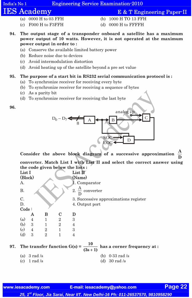
96.
A
D
B C
SOCEOC
analog i/p
8D – D0 7
Consider the above block diagram of a successive approximation AD
converter. Match List I with List II and select the correct answer using the code given below the lists : List I List II (Block) (Name) A. 1. Comparator
B. 2. AD
converter
C. 3. Successive approximations register D. 4. Output port Code : A B C D (a) 4 1 2 3 (b) 3 1 2 4 (c) 4 2 1 3 (d) 3 2 1 4
97. The transfer function G(s) = 10(3s 1)+
has a corner frequency at :
(a) 3 rad /s (b) 0⋅33 rad /s (c) 1 rad /s (d) 30 rad /s

India’s No 1 Engineering Service Examination-2010 IES Academy E & T Engineering Paper-II
www.iesacademy.com E-mail: [email protected] Page 23
25, 1st Floor, Jia Sarai, Near IIT. New Delhi-16 Ph: 011-26537570, 9810958290
98. A 10 bit AD
converter is used to digitize an analog signal in the 0 to 5 V
range. The maximum peak to peak ripple voltage that can be allowed in the DC supply voltage is, nearly : (a) 100 mV (b) 50 mV (c) 25 mV (d) 5⋅0 mV
99. Which one of the following represents the pole-zero location in the s-plane for lead-compensator?
(a)
jω
σ
(b)
jω
σ
(c)
jω
σ
(d)
jω
σ
100. Consider the following application : 1. Wind tunnel simulation 2. Real-time video viewing A computer is used for :

India’s No 1 Engineering Service Examination-2010 IES Academy E & T Engineering Paper-II
www.iesacademy.com E-mail: [email protected] Page 24
25, 1st Floor, Jia Sarai, Near IIT. New Delhi-16 Ph: 011-26537570, 9810958290
(a) Neither 1 nor 2 (b) Both 1 and 2 (c) 1 only (d) 2 only
Directions :– Each of the next Twenty (20) items consists of two statements, one
labelled as the ‘Assertion (A)’ and the other as ‘Reason (R)’. You are to examine these two statements carefully and select the answers to these items using the codes given below :
Codes : (a) Both A and R are individually true and R is the correct explanation of A (b) Both A and R are individually true but R is not the correct explanation of A (c) A is true but R is false (d) A is false but R is true
101. Assertion (A) : The TTL NAND gate in tristate output configuration can be used for a bus arrangement with more than one gate output connected to a common line.
Reason (R) : The tristate configuration has a control input, which can detach a
logic level 01
⎛ ⎞⎜ ⎟⎝ ⎠
from coming onto the bus line.
102. Assertion (A) : Integral windup effect in controller causes excessive overshoot.
Reason (R) : Presence of saturation in controller and actuator deteriorates the PID control.
103. Assertion (A) : Steady state error can be reduced by increasing integral gain. Reason (R) : Overshoot can be reduced by increasing derivative gain.
104. Assertion (A) : Source produces two symbols A and B with probability 34
and 14
respectively. For error free transmission this source should be cooled using Shannon-Fano code.
Reason (R) : For better transmission efficiency, source and channel must be matched.
105. Assertion (A) : Frequency modulation and phase modulation both produce different set of frequency bands for the same modulation depth.
Reason (R) : Frequency modulation and phase modulation vary the carrier phase angle or its rate.
106. Assertion (A) : In amplitude modulation systems the value of modulation index should be around 1.
Reason (R) : The power carried in the intelligence carrying sidebands increases with the modulation index.
107. Assertion (A) : When coding signals like speech signals a-law or μ-law quantizers are used.
Reason (R) : A-law and μ-law quantizers occupy smaller bandwidth than uniform quantizers.
108. Assertion (A) : PCM / FM systems transmit PCM pulses by modulating a high frequency carrier and hence occupy large band width and eliminate distortion.

India’s No 1 Engineering Service Examination-2010 IES Academy E & T Engineering Paper-II
www.iesacademy.com E-mail: [email protected] Page 25
25, 1st Floor, Jia Sarai, Near IIT. New Delhi-16 Ph: 011-26537570, 9810958290
Reason (R) : Large bandwidth ensures SNR tide off and hence distortionless transmission is ensured.
109. Assertion (A) : It is not necessary to incorporate a very low noise amplifier in a communication satellite.
Reason (R) : The noise temperature of the satellite antenna is usually high, since the beam is covered by the earth.
110. Assertion (A) : A magnetron is not an amplifier, but an oscillator producing microwaves.
Reason (R) : In making their circular passes in the interaction space of a magnetron, the electrons excite the resonant cavities into oscillations.
111. Assertion (A) : The slow wave wave structure of a TWT is provided with an attenuator.
Reason (R) : This is done for preventing oscillations in the device.
112. Assertion (A) : Generally, magnetrons are operated in π modes. Reason (R) : Frequency for π mode can be easily separated from adjacent modes.
113. Assertion (A) : The impedance of a matched load is equal to characteristic impedance of line.
Reason (R) : A matched termination absorbs the entire power incident on it.
114. Assertion (A) : In microwave point-to-point communication systems, parabolic reflector antennas are generally used.
Reason (R) : A parabolic reflector antenna receiver has the property of focusing all axial rays to its focus and when used as transmitter with a feed at the focus, it will generate parallel beams along the axis with a pencil beam radiation pattern.
115. Assertion (A) : A Cassegrain antenna uses a main paraboloidal reflector and a relatively small hyperboloidal sub-reflector with a small horn-feed at the vertex of the main paraboloidal reflector.
Reason (R) : The optical technique developed by William Cassegrain was used in telescope design to obtain large magnification with a physically short telescope. This configuration is found to be effective in the design of microwave antenna also.
116. Assertion (A) : In microwave communication links, intensive fading at 18 GHz band occurs due to rain-drop attenuation.
Reason (R) : Collective scattering from water droplets in the atmosphere will result in diminution of energy in the forward path and this is maximum at the 18 GHz band because the criterion for scattering are more satisfied by the wavelength dimensions at these frequencies.
117. Assertion (A) : In satellite communication technique, frequency reuse effectively doubles the bandwidth and information capacity of a satellite.
Reason (R) : Electromagnetic waves radiated from a transmitting antenna could be received by a distant receiving antenna by tuning the receiver in terms of frequency and polarization.
118. Assertion (A) : The main difference between a microprocessor and a microcontroller is that the former does not have any on-chip main memory whereas latter has.
Reason (R) : A microprocessor does not need memory to run programs.

India’s No 1 Engineering Service Examination-2010 IES Academy E & T Engineering Paper-II
www.iesacademy.com E-mail: [email protected] Page 26
25, 1st Floor, Jia Sarai, Near IIT. New Delhi-16 Ph: 011-26537570, 9810958290
119. Assertion (A) : Logic analyzer offers a “delayed sweep”. Reason (R) : Because the logic analyzer “sweep” is really a clock signal.
120. Assertion (A) : When you turn on your PC, a process called POST (power-on-self-test) begins with an electrical signal.
Reason (R) : The electrical signal restores left over data from the chip’s internal memory register.