Ieeepro techno solutions ieee 2014 embedded project on shoe wearable sensors for detecting foot...
4
Proceedings of 5 th IRF International Conference, Chennai, 23 rd March. 2014, ISBN: 978-93-82702-67-2 24 ON SHOE WEARABLE SENSORS FOR DETECTING FOOT NEUROPATHY 1 J.JANE CRISPINO, 2 C.SHEEBA JOICE 1 Department of Electronics and Communication, Saveetha Engineering College, Chennai 2 Professor, Department of ECE, Saveetha Engineering College, Chennai. Abstract - Foot Neuropathy is a serious medical disorder and can be prevented by the early detection of abnormal pressure patterns under the foot. By a sending imperceptible vibration through the feet of Parkinson’s disease (PD) patients significantly improves the damaged nerves and stimulates blood flow. The methods used in clinics are based on complex motion laboratory settings or simple timing outcomes using stop watches and Timed Up and Go test. The goal of this paper is to design and build a low-cost foot pressure and foot movement analysis and blood flow stimulation system, embedded within smart footwear which a patient can wear at any place to monitor his or her foot pressure distribution to identify and diagnose foot neuropathy as early as possible. To improve the blood flow the smart footwear has a set of miniature vibrating motors that stimulate the nerves by vibrating in different amplitude that can be configured individually, started and stopped by the user. The smart footwear will collect data from inertial sensors and periodically transfer this data to the handheld unit where it will be stored in a memory card for future reference or for an analysis by a doctor. Keywords – Parkinson Disease, Vibrating motors, Timed up and go, inertial sensors. I. INTRODUCTION Parkinson’s disease is a complex neurodegenerative disease requiring close monitoring and regular assessment. PD affects a large group of the worldwide population. It is estimated that worldwide 4 million people are living with Parkinson’s disease. The disease affects a part of the brain known as the “Substania Nigra” which controls movement in the body. Essentially there is a lack of dopamine (Neurotransmitter) in the brain when Parkinson’s disease is present. It is a progressive disease that usually affects people over 50 years of age however younger people can also be diagnosed with this disease and this is known as early onset Parkinson’s disease (PD). There are a wide range of features associated with the disease making diagnosis difficult. Persons with PD may require frequent and time consuming visits to specialist centers for assessment and monitoring. Although the main features of PD are motor related and therefore impact considerably on daily life many people with the disease suggest features that are not motor related can affect quality of life more so than the motor related features. Home- based monitoring of PD is a laudable aim that has the potential to reduce the necessity to attend frequent consultations with specialist personnel in addition to offering potentially more precise and continuous monitoring paradigms sensitively assessing disease progression and medication effects. The Timed Up and Go (TUG) test is a widely used clinical test to assess balance, mobility and fall risk in the elderly and in patients with Parkinson’s disease (PD). It consists of rising from a chair, walking 3m at preferred speed, turning around, returning and sitting. It is simple and easy to perform in the clinic. The traditional clinical outcome of this test is its total duration, which is usually measured by a stopwatch. Gait is a motor task which is particularly sensitive to ON–OFF changes in PD. When OFF, PD patients walk slowly with short shuffling steps affecting the trajectory of foot, reduced stride length, and less regular cycle, as shown by the increase of inter stride variability. II. METHODOLOGY FOR FOOT NEUROPATHY ANALYZER The software used is Embedded C and the developing tool is proteus. The microcontroller used is ARM CORTEX M3. It consists of Accelerometer and Flexi force sensor where Accelerometer is a device used to sense the vibration and force induced by the foot and Flexi force sensor is used to sense the pressure distribution under foot. Fig. 1 Block diagram of foot neuropathy analyzer. The block diagram of foot neuropathy analyzer is shown in Fig.1. The pressure distribution in foot is given as input to inertial sensors which includes
-
Upload
srinivasanece7 -
Category
Engineering
-
view
117 -
download
0
Transcript of Ieeepro techno solutions ieee 2014 embedded project on shoe wearable sensors for detecting foot...

On Shoe Wearable Sensors For Detecting Foot Neuropathy
Proceedings of 5th IRF International Conference, Chennai, 23rd March. 2014, ISBN: 978-93-82702-67-2
24
ON SHOE WEARABLE SENSORS FOR DETECTING FOOT NEUROPATHY
1J.JANE CRISPINO, 2C.SHEEBA JOICE
1Department of Electronics and Communication, Saveetha Engineering College, Chennai
2Professor, Department of ECE, Saveetha Engineering College, Chennai.
Abstract - Foot Neuropathy is a serious medical disorder and can be prevented by the early detection of abnormal pressure patterns under the foot. By a sending imperceptible vibration through the feet of Parkinson’s disease (PD) patients significantly improves the damaged nerves and stimulates blood flow. The methods used in clinics are based on complex motion laboratory settings or simple timing outcomes using stop watches and Timed Up and Go test. The goal of this paper is to design and build a low-cost foot pressure and foot movement analysis and blood flow stimulation system, embedded within smart footwear which a patient can wear at any place to monitor his or her foot pressure distribution to identify and diagnose foot neuropathy as early as possible. To improve the blood flow the smart footwear has a set of miniature vibrating motors that stimulate the nerves by vibrating in different amplitude that can be configured individually, started and stopped by the user. The smart footwear will collect data from inertial sensors and periodically transfer this data to the handheld unit where it will be stored in a memory card for future reference or for an analysis by a doctor. Keywords – Parkinson Disease, Vibrating motors, Timed up and go, inertial sensors. I. INTRODUCTION Parkinson’s disease is a complex neurodegenerative disease requiring close monitoring and regular assessment. PD affects a large group of the worldwide population. It is estimated that worldwide 4 million people are living with Parkinson’s disease. The disease affects a part of the brain known as the “Substania Nigra” which controls movement in the body. Essentially there is a lack of dopamine (Neurotransmitter) in the brain when Parkinson’s disease is present. It is a progressive disease that usually affects people over 50 years of age however younger people can also be diagnosed with this disease and this is known as early onset Parkinson’s disease (PD). There are a wide range of features associated with the disease making diagnosis difficult. Persons with PD may require frequent and time consuming visits to specialist centers for assessment and monitoring. Although the main features of PD are motor related and therefore impact considerably on daily life many people with the disease suggest features that are not motor related can affect quality of life more so than the motor related features. Home-based monitoring of PD is a laudable aim that has the potential to reduce the necessity to attend frequent consultations with specialist personnel in addition to offering potentially more precise and continuous monitoring paradigms sensitively assessing disease progression and medication effects. The Timed Up and Go (TUG) test is a widely used clinical test to assess balance, mobility and fall risk in the elderly and in patients with Parkinson’s disease (PD). It consists of rising from a chair, walking 3m at preferred speed, turning around, returning and sitting. It is simple and easy to perform in the clinic. The
traditional clinical outcome of this test is its total duration, which is usually measured by a stopwatch. Gait is a motor task which is particularly sensitive to ON–OFF changes in PD. When OFF, PD patients walk slowly with short shuffling steps affecting the trajectory of foot, reduced stride length, and less regular cycle, as shown by the increase of inter stride variability. II. METHODOLOGY FOR FOOT
NEUROPATHY ANALYZER The software used is Embedded C and the developing tool is proteus. The microcontroller used is ARM CORTEX M3. It consists of Accelerometer and Flexi force sensor where Accelerometer is a device used to sense the vibration and force induced by the foot and Flexi force sensor is used to sense the pressure distribution under foot.
Fig. 1 Block diagram of foot neuropathy analyzer.
The block diagram of foot neuropathy analyzer is shown in Fig.1. The pressure distribution in foot is given as input to inertial sensors which includes
On Shoe Wearable Sensors For Detecting Foot Neuropathy
Proceedings of 5th IRF International Conference, Chennai, 23rd March. 2014, ISBN: 978-93-82702-67-2
25
accelerometer gyroscope and flexi force sensors. Accelerometer is used to measure the force applied. Flexi force sensors are used to measure the pressure distribution in foot.
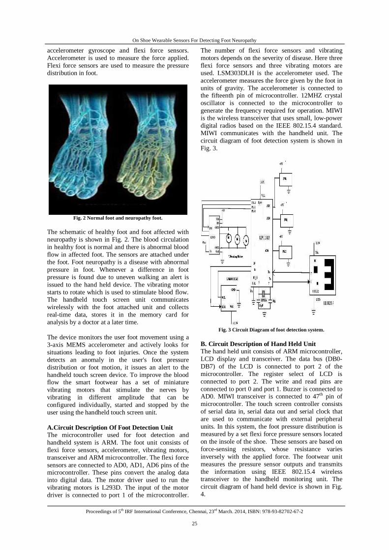
Fig. 2 Normal foot and neuropathy foot.
The schematic of healthy foot and foot affected with neuropathy is shown in Fig. 2. The blood circulation in healthy foot is normal and there is abnormal blood flow in affected foot. The sensors are attached under the foot. Foot neuropathy is a disease with abnormal pressure in foot. Whenever a difference in foot pressure is found due to uneven walking an alert is issued to the hand held device. The vibrating motor starts to rotate which is used to stimulate blood flow. The handheld touch screen unit communicates wirelessly with the foot attached unit and collects real-time data, stores it in the memory card for analysis by a doctor at a later time. The device monitors the user foot movement using a 3-axis MEMS accelerometer and actively looks for situations leading to foot injuries. Once the system detects an anomaly in the user's foot pressure distribution or foot motion, it issues an alert to the handheld touch screen device. To improve the blood flow the smart footwear has a set of miniature vibrating motors that stimulate the nerves by vibrating in different amplitude that can be configured individually, started and stopped by the user using the handheld touch screen unit. A.Circuit Description Of Foot Detection Unit The microcontroller used for foot detection and handheld system is ARM. The foot unit consists of flexi force sensors, accelerometer, vibrating motors, transceiver and ARM microcontroller. The flexi force sensors are connected to AD0, AD1, AD6 pins of the microcontroller. These pins convert the analog data into digital data. The motor driver used to run the vibrating motors is L293D. The input of the motor driver is connected to port 1 of the microcontroller.
The number of flexi force sensors and vibrating motors depends on the severity of disease. Here three flexi force sensors and three vibrating motors are used. LSM303DLH is the accelerometer used. The accelerometer measures the force given by the foot in units of gravity. The accelerometer is connected to the fifteenth pin of microcontroller. 12MHZ crystal oscillator is connected to the microcontroller to generate the frequency required for operation. MIWI is the wireless transceiver that uses small, low-power digital radios based on the IEEE 802.15.4 standard. MIWI communicates with the handheld unit. The circuit diagram of foot detection system is shown in Fig. 3.
Fig. 3 Circuit Diagram of foot detection system.
B. Circuit Description of Hand Held Unit The hand held unit consists of ARM microcontroller, LCD display and transceiver. The data bus (DB0-DB7) of the LCD is connected to port 2 of the microcontroller. The register select of LCD is connected to port 2. The write and read pins are connected to port 0 and port 1. Buzzer is connected to AD0. MIWI transceiver is connected to 47th pin of microcontroller. The touch screen controller consists of serial data in, serial data out and serial clock that are used to communicate with external peripheral units. In this system, the foot pressure distribution is measured by a set flexi force pressure sensors located on the insole of the shoe. These sensors are based on force-sensing resistors, whose resistance varies inversely with the applied force. The footwear unit measures the pressure sensor outputs and transmits the information using IEEE 802.15.4 wireless transceiver to the handheld monitoring unit. The circuit diagram of hand held device is shown in Fig. 4.

On Shoe Wearable Sensors For Detecting Foot Neuropathy
Proceedings of 5th IRF International Conference, Chennai, 23rd March. 2014, ISBN: 978-93-82702-67-2
26
Fig. 4 Circuit Diagram of Hand Held Device.
III. RESULT AND DISCUSSIONS
The vibrating motors and sensors are interfaced with the microcontroller. Here two flexi force sensors are used. When an anomaly in the foot is detected then the vibrating motor rotates. The vibrating motor stimulates the blood. The pressure in the foot is displayed in the LCD screen. When there is equal foot pressure then there is no rotation in vibrating motor. The circuit for foot neuropathy analyzer and blood flow stimulator for equal pressure is shown in Fig.5 and Foot pressure detection system when there is unequal pressure in the foot is shown in Fig. 6.
RA0/AN02
RA1/AN13
RA2/AN2/VREF-/CVREF4
RA4/T0CKI/C1OUT6
RA5/AN4/SS/C2OUT7
RE0/AN5/RD8
RE1/AN6/WR9
RE2/AN7/CS10
OSC1/CLKIN13
OSC2/CLKOUT14
RC1/T1OSI/CCP2 16
RC2/CCP1 17
RC3/SCK/SCL 18
RD0/PSP0 19
RD1/PSP1 20
RB7/PGD 40RB6/PGC 39RB5 38RB4 37RB3/PGM 36RB2 35RB1 34RB0/INT 33
RD7/PSP7 30RD6/PSP6 29RD5/PSP5 28RD4/PSP4 27RD3/PSP3 22RD2/PSP2 21
RC7/RX/DT 26RC6/TX/CK 25RC5/SDO 24RC4/SDI/SDA 23
RA3/AN3/VREF+5
RC0/T1OSO/T1CKI 15
MCLR/Vpp/THV1
U1
D7
14D
613
D5
12D
411
D3
10D
29
D1
8D
07
E6
RW5
RS
4
VSS
1V
DD
2V
EE3
LCD1LM016L
85%
FSR1
1k
IN12 OUT1 3
OUT2 6
OUT3 11
OUT4 14
IN27
IN310
IN415
EN11
EN29
VS
8
VSS
16
GND GND
U2
L293D
85%
FSR2
1k
A
B
C
D
Fig 5.Circuit for Foot Neuropathy Analyzer And Blood Flow
Stimulator for Equal Pressure
The flexi force sensor 1 is connected to analog channel AN0 and the flexi force sensor 2 is connected to analog channel AN1.The flexi force sensors are denoted by FSR1 and FSR2.L293D is the motor driver used to drive the vibrating motor. The speed of the vibrating motor is displayed digitally. In Fig. 5, the output of the flexi force sensors FSR1 and FSR2 are found to be equal pressure. Both the sensor outputs are 87. Since there is equal pressure there is no rotation in the vibrating motor. In Fig. 6, the output of flexi force sensor 1 is 87 and the output of flexi force sensor 2 is 84. Since there is a difference in pressure the vibrating motor starts to rotate which is driven by motor driver.
RA0/AN02
RA1/AN13
RA2/AN2/VREF-/CVREF4
RA4/T0CKI/C1OUT6
RA5/AN4/SS/C2OUT7
RE0/AN5/RD8
RE1/AN6/WR9
RE2/AN7/CS10
OSC1/CLKIN13
OSC2/CLKOUT14
RC1/T1OSI/CCP2 16
RC2/CCP1 17
RC3/SCK/SCL 18
RD0/PSP0 19
RD1/PSP1 20
RB7/PGD 40RB6/PGC 39RB5 38RB4 37RB3/PGM 36RB2 35RB1 34RB0/INT 33
RD7/PSP7 30RD6/PSP6 29RD5/PSP5 28RD4/PSP4 27RD3/PSP3 22RD2/PSP2 21
RC7/RX/DT 26RC6/TX/CK 25RC5/SDO 24RC4/SDI/SDA 23
RA3/AN3/VREF+5
RC0/T1OSO/T1CKI 15
MCLR/Vpp/THV1
U1
D7
14D
613
D5
12D
411
D3
10D
29
D1
8D
07
E6
RW5
RS
4
VSS
1V
DD2
VEE
3
LCD1LM016L
85%
FSR1
1k
IN12 OUT1 3
OUT2 6
OUT3 11
OUT4 14
IN27
IN310
IN415
EN11
EN29
VS
8
VSS
16
GND GND
U2
L293D
83%
FSR2
1k
A
B
C
D
Fig. 6 Foot pressure detection system when there is unequal
pressure in the foot.
The TABLE I shows the FSR value and motor rotation based on it. When FSR values of Flexi force sensor1 and Flexi force sensor2 are equal then motor does not undergo rotation. If both FSR1 and FSR2 values are equal, the vibrating motor rotates.
TABLE 1 FSR VALUE & VIBRATING MOTOR FSR VALUE Vibrating Motor Equal No Rotation Not Equal Rotates
Figure7 shows the hardware of foot detection unit. The foot unit consists of flexi force sensors, accelerometer, vibrating motors, MIWI transceiver and ARM microcontroller. Figure8 shows the hardware of handheld unit. The hand held unit consists of ARM microcontroller, LCD display and MIWI transceiver.

On Shoe Wearable Sensors For Detecting Foot Neuropathy
Proceedings of 5th IRF International Conference, Chennai, 23rd March. 2014, ISBN: 978-93-82702-67-2
27
Fig 7.Foot Detection System
Fig 8.Handheld Unit
CONCLUSION This paper discussed about the detection of foot neuropathy as early as possible in a home based environment. Flexi force sensors are used to measure the pressure in foot and if any abnormality is detected in the foot pressure it is displayed on the hand held device. The vibrating motors are rotated to stimulate the blood flow. Thus a low-cost foot pressure and foot movement analysis and blood flow stimulation system, embedded within smart footwear is developed which a patient can wear at any place to monitor his or her foot pressure distribution to identify and diagnose foot neuropathy as early as possible.
REFERENCES
[1] Benoit Mariani, Mayt´e Castro Jim´enez, Franc¸ois J. G. Vingerhoets, and Kamiar Aminian, “On-Shoe Wearable Sensors for Gait and Turning Assessment of Patients With Parkinson’s Disease”, in IEEE Transactions on Biomedical Eng., 2013, vol.60, No. 1, p.p.155-158.
[2] Bor-Rong Chen, Shyamal Patel, Thomas Buckley, Ramona Rednic, Douglas J. McClure, Ludy Shih, Daniel Tarsy, Matt Welsh, and Paolo Bonato,“A Web-Based System for Home Monitoring of Patients With Parkinson’s Disease Using Wearable Sensors”, in IEEE Transactions on Bio medical Eng., 2011, vol.58, No.3, p.p.831-836.
[3] L. Cunningham, S. Mason, C. Nugent, G. Moore, D. Finlay, and D. Craig,“Home-Based Monitoring and Assessment of Parkinson’s Disease”, in IEEE Transactions on Bio medical Eng., 2011 vol. 15, No. 1, p.p.47-53.
[4] Franco Valzania Luca Palmerini, Sabato Mellone, Guido Avanzolini, and Lorenzo Chiari, “Quantification of Motor Impairment in Parkinson’s Disease Using an Instrumented Timed Up and Go Test”, in IEEE Transactions on Neural sys and Rehabiliation., 2013, vol. 21, No. 4, p.p.664-673.
[5] George Rigas, Alexandros T. Tzallas et al.,“Assessment of Tremor Activity in the Parkinson’s Disease Using a Set of Wearable Sensors”, in IEEE Transactions on Bio medical Eng., 2012, vol. 16, No. 3, p.p.478-487.
[6] Nicholas Wickstrom, et al., “A New Measure of Movement Symmetry in Early Parkinson’s Disease Patients Using Symbolic Processing of Inertial Sensor Data”, in IEEE Transactions on Bio medical Eng., 2011, vol. 58, No. 7, p.p.2127-2135,2011.
[7] M.M.K. Oishi, M.J. McKeown, “Switched manual pursuit tracking to measure motor performance in Parkinson’s disease”, in IET Control Theory Appl., 2011, Vol. 5, Iss. 17, p.p.1970–1977.
[8] Shyamal Patel, Konrad Lorincz, Richard Hughes, Nancy Huggins, John Grow don, David Standaert, Metin Akay, “Monitoring Motor Fluctuations in Patients With Parkinson’s Disease Using Wearable Sensors”, in IEEE Transactions on Bio medical Eng., 2009 vol. 13, No. 6, p.p.864-873.
[9] I. Tien, S. D. Glaser, and M. J. Aminoff, “Characterization of gait abnormalities in Parkinson’s disease using a wireless inertial sensor system”, in IEEE Transactions on Bio medical Eng., 2010 p.p.3353-3356.
[10] Tjitske Heida, Jeroen P. P. van Vugt, Jan A. G. Geelen“Ambulatory Monitoring of Activities and Motor Symptoms in Parkinson’s Disease”, in IEEE Transactions on Bio medical Eng., 2010, vol. 57, No. 11, p.p.2778-2786.