IEEE TRANSACTIONS ON COMPUTER-AIDED DESIGN · PDF file928 IEEE TRANSACTIONS ON COMPUTER-AIDED...
11
IEEE TRANSACTIONS ON COMPUTER-AIDED DESIGN OF INTEGRATED CIRCUITS AND SYSTEMS, VOL. 36, NO. 6, JUNE 2017 927 Reconfigurable Constant Multiplication for FPGAs Konrad Möller, Martin Kumm, Member, IEEE, Marco Kleinlein, and Peter Zipf, Member, IEEE Abstract—This paper introduces a new heuristic to generate pipelined run-time reconfigurable constant multipliers for field- programmable gate arrays (FPGAs). It produces results close to the optimum. It is based on an optimal algorithm which fuses already optimized pipelined constant multipliers generated by an existing heuristic called reduced pipelined adder graph (RPAG). Switching between different single or multiple constant outputs is realized by the insertion of multiplexers. The heuristic searches for a solution that results in minimal multiplexer overhead. Using the proposed heuristic reduces the run-time of the fusion process, which raises the usability and application domain of the proposed method of run-time reconfiguration. An extensive evaluation of the proposed method confirms a 9%–26% FPGA resource reduction on average compared to previous work. For reconfig- urable multiple constant multiplication, resource savings of up to 75% can be shown compared to a standard generic lookup table based multiplier. Two low level optimizations are presented, which further reduce resource consumption and are included into an automatic VHDL code generation based on the FloPoCo library. Index Terms—Field programmable gate arrays, multiplying circuits, reconfigurable architectures. I. I NTRODUCTION T HE MULTIPLICATION with constant coefficients is an essential operation in digital signal processing. Initially one of the reasons to put embedded multipliers or DSP blocks into the fabric of field-programmable gate arrays (FPGAs) was to reduce the performance gap between application spe- cific integrated circuits (ASICs) and FPGAs. Nevertheless, the price to pay for those fixed coarse-grained blocks is their inflexibility in word size and limited quantity. Limited quan- tity is particularly critical in industrial applications, when cheaper and rather small FPGAs with only few DSP blocks have to be chosen due to price pressure. Thus, logic-based constant multiplication methods are needed. Optimizing the implementation of this operation is well studied. Switching between a given set of constants of such multipliers dur- ing run-time instead of using larger generic multipliers is important to realize hardware efficient run-time adaptable fil- ters [1]–[3], discrete cosine transformation and fast Fourier transform implementations [4] as well as multistage filters for decimation or interpolation like polyphase finite-impulse response (FIR) filters [5]. A reconfigurable constant multiplier Manuscript received February 29, 2016; revised June 2, 2016 and August 1, 2016; accepted September 8, 2016. Date of publication October 3, 2016; date of current version May 18, 2017. This paper was recommended by Associate Editor Y. Wang. The authors are with the Digital Technology Group, University of Kassel, 34121 Kassel, Germany (e-mail: [email protected]; [email protected]; [email protected]; [email protected]). Digital Object Identifier 10.1109/TCAD.2016.2614775 Fig. 1. Reconfigurable single constant multiplier which can be switched between the constants 1912, 1111, and 1331. is a multiplication circuit in which the scaling constant can be chosen from a limited predefined set of constants during run- time. For the given application domains two to six of such adjustable coefficient sets are common. The switching during run-time is achieved by inserting multiplexers into several con- stant multiplication circuits, to achieve a reuse of redundant partial circuits and thus a reduction of required resources. The problem is to find the best possible solution when inserting the fusing multiplexers. In order to avoid large routing delays pipelining is used for high speed applications. In contrast to ASICs, this is specifically advisable for FPGA designs [6], due to their inherent performance disadvantage. An example for such a pipelined reconfigurable constant multiplier which can be switched between the constants 1912, 1111, and 1331 can be found in Fig. 1. Pipeline registers are inserted after each stage which includes registers in the multiplexer stages. The wires can be associated with a left shift and a sign. The value vector noted besides each operation corresponds to the intermediate or output factors for a specific multiplexer config- uration. A switchable adder/subtractor is depicted as an adder with an additional sign vector input. A common way to realize multiplier-less single and multiple constant multiplication (MCM) for fixed con- stants is using additions, subtractions, and bit shifts. In general, finding an optimal solution for single constant multiplication (SCM) proved to be NP-complete as shown by Cappello and Steiglitz [7], so optimal solutions can only 0278-0070 c 2016 IEEE. Personal use is permitted, but republication/redistribution requires IEEE permission. See http://www.ieee.org/publications_standards/publications/rights/index.html for more information.
Transcript of IEEE TRANSACTIONS ON COMPUTER-AIDED DESIGN · PDF file928 IEEE TRANSACTIONS ON COMPUTER-AIDED...

IEEE TRANSACTIONS ON COMPUTER-AIDED DESIGN OF INTEGRATED CIRCUITS AND SYSTEMS, VOL. 36, NO. 6, JUNE 2017 927
Reconfigurable Constant Multiplication for FPGAsKonrad Möller, Martin Kumm, Member, IEEE, Marco Kleinlein, and Peter Zipf, Member, IEEE
Abstract—This paper introduces a new heuristic to generatepipelined run-time reconfigurable constant multipliers for field-programmable gate arrays (FPGAs). It produces results close tothe optimum. It is based on an optimal algorithm which fusesalready optimized pipelined constant multipliers generated by anexisting heuristic called reduced pipelined adder graph (RPAG).Switching between different single or multiple constant outputsis realized by the insertion of multiplexers. The heuristic searchesfor a solution that results in minimal multiplexer overhead. Usingthe proposed heuristic reduces the run-time of the fusion process,which raises the usability and application domain of the proposedmethod of run-time reconfiguration. An extensive evaluationof the proposed method confirms a 9%–26% FPGA resourcereduction on average compared to previous work. For reconfig-urable multiple constant multiplication, resource savings of upto 75% can be shown compared to a standard generic lookuptable based multiplier. Two low level optimizations are presented,which further reduce resource consumption and are includedinto an automatic VHDL code generation based on the FloPoColibrary.
Index Terms—Field programmable gate arrays, multiplyingcircuits, reconfigurable architectures.
I. INTRODUCTION
THE MULTIPLICATION with constant coefficients is anessential operation in digital signal processing. Initially
one of the reasons to put embedded multipliers or DSP blocksinto the fabric of field-programmable gate arrays (FPGAs)was to reduce the performance gap between application spe-cific integrated circuits (ASICs) and FPGAs. Nevertheless, theprice to pay for those fixed coarse-grained blocks is theirinflexibility in word size and limited quantity. Limited quan-tity is particularly critical in industrial applications, whencheaper and rather small FPGAs with only few DSP blockshave to be chosen due to price pressure. Thus, logic-basedconstant multiplication methods are needed. Optimizing theimplementation of this operation is well studied. Switchingbetween a given set of constants of such multipliers dur-ing run-time instead of using larger generic multipliers isimportant to realize hardware efficient run-time adaptable fil-ters [1]–[3], discrete cosine transformation and fast Fouriertransform implementations [4] as well as multistage filtersfor decimation or interpolation like polyphase finite-impulseresponse (FIR) filters [5]. A reconfigurable constant multiplier
Manuscript received February 29, 2016; revised June 2, 2016 andAugust 1, 2016; accepted September 8, 2016. Date of publicationOctober 3, 2016; date of current version May 18, 2017. This paper wasrecommended by Associate Editor Y. Wang.
The authors are with the Digital Technology Group, University ofKassel, 34121 Kassel, Germany (e-mail: [email protected];[email protected]; [email protected]; [email protected]).
Digital Object Identifier 10.1109/TCAD.2016.2614775
Fig. 1. Reconfigurable single constant multiplier which can be switchedbetween the constants 1912, 1111, and 1331.
is a multiplication circuit in which the scaling constant can bechosen from a limited predefined set of constants during run-time. For the given application domains two to six of suchadjustable coefficient sets are common. The switching duringrun-time is achieved by inserting multiplexers into several con-stant multiplication circuits, to achieve a reuse of redundantpartial circuits and thus a reduction of required resources. Theproblem is to find the best possible solution when insertingthe fusing multiplexers. In order to avoid large routing delayspipelining is used for high speed applications. In contrast toASICs, this is specifically advisable for FPGA designs [6],due to their inherent performance disadvantage. An examplefor such a pipelined reconfigurable constant multiplier whichcan be switched between the constants 1912, 1111, and 1331can be found in Fig. 1. Pipeline registers are inserted aftereach stage which includes registers in the multiplexer stages.The wires can be associated with a left shift and a sign. Thevalue vector noted besides each operation corresponds to theintermediate or output factors for a specific multiplexer config-uration. A switchable adder/subtractor is depicted as an adderwith an additional sign vector input.
A common way to realize multiplier-less single andmultiple constant multiplication (MCM) for fixed con-stants is using additions, subtractions, and bit shifts. Ingeneral, finding an optimal solution for single constantmultiplication (SCM) proved to be NP-complete as shownby Cappello and Steiglitz [7], so optimal solutions can only
0278-0070 c© 2016 IEEE. Personal use is permitted, but republication/redistribution requires IEEE permission.See http://www.ieee.org/publications_standards/publications/rights/index.html for more information.

928 IEEE TRANSACTIONS ON COMPUTER-AIDED DESIGN OF INTEGRATED CIRCUITS AND SYSTEMS, VOL. 36, NO. 6, JUNE 2017
be found for limited constant bit widths. Optimal SCM solu-tions for constants of up to 12 bit [8] were first extended toconstants of up to 19 bit [9] and further extended for con-stants of up to 32 bit [10]. Moreover, there are good SCMheuristics called RAG-n, BHM [11], and Hcub [12] whosesource code as well as an online SCM generator are pro-vided on the SPIRAL project webpage [13]. When FPGAsare the target technology, solutions which consider pipeliningduring optimization have to be preferred to avoid large rout-ing delays [6]. The problem of finding solutions for pipelinedadder graphs (PAGs) for SCM as well as for MCM, which candirectly take advantage of the registers provided in an FPGA’sbasic logic element (BLE), is solved by a heuristic calledreduced pipelined adder graph (RPAG) [14]. This heuristicwas shown to outperform state-of-the-art MCM methods likeHcub [12] when these are optimally pipelined [15] and is thusbe used as base for the reconfigurable constant multiplicationshown in this paper. The source code of this heuristic is alsoavailable online [16].
Finding the run-time reconfiguration of SCM and MCMadder graphs is a generalization of the basic SCM/MCMproblem and thus also NP-complete. However, solutionswere presented which are able to find reconfigurableSCMs (RSCM). First of all there are different solutions target-ing ASICs, all focusing on multiplexer-based reconfiguration.In the method of Tummeltshammer et al. [17] several opti-mized SCM graphs are fused by a recursive algorithm calledDAG fusion. Two SCM graphs are fused with minimal hard-ware effort by inserting multiplexers to switch between thedifferent constants. Further coefficients can be included byrecursively adding the related SCMs to the existing RSCM.Similarities between different coefficients in the canonicalsigned digit (CSD) representation of constants are exploitedby Chen and Chang [18] to realize RSCMs. Identical patternsin the CSD representation of constants are searched and fusedusing multiplexers to be able to switch between the differ-ent shifts and interconnections to realize a specific constant.Faust et al. [5] used an adder graph based approach with spe-cial focus on minimal logic depth. In addition to the methodsdescribed earlier, their algorithm does not only provide solu-tions for RSCM but also for reconfigurable MCM (RMCM).Such RMCM are also provided by ORPHEUS [2] which isable to fuse MCM solutions provided by Hcub [12] with aheuristic. Alterative concepts to realize RMCMs are evaluatedduring the algorithm run-time and the best overall solutionis selected. The presented algorithms for RSCM and RMCM,respectively, do not consider pipelining or other FPGA specificissues as their focus is on ASIC implementations.
There is an FPGA-specific algorithm called ReMBmethod [1] which was further analyzed and extended in [19]by our group. An RSCM is constructed from basic struc-tures that fit into the BLEs of FPGAs. This procedure islimited to small problem sizes due to a very high mem-ory consumption [19] and does not consider pipelining. Aspipelined solutions are required for high speed applicationson FPGAs, there is an optimal adder graph based algorithmfor RSCM and RMCM with focus on pipelined realizationsproposed by our group [20]. The idea of DAG fusion [17]
Fig. 2. RPAG solutions for the constants 1912, 1111, and 1331.
is picked up as already optimized PAGs are fused. Insteadof fusing only two PAGs in one optimization run, all PAGsof the required constants are considered in one single opti-mization run to produce a better, multiplexer-aware pipelinedrealization. However, the optimal approach can only be usedfor small problems because of the complexity of a full searchover all possible fusing solutions. Hence, a good heuristicmethod is required which provides solutions close to the opti-mum. This heuristic is presented and analyzed in Section II.Moreover, the proposed heuristic supports the use of PAGsconsisting of ternary adders [21]–[23], which turns out tofurther improve the results. In Section III, some low leveloptimizations are provided to exploit the FPGA resourcesin the best possible way. The results and a comparisonwith previous work and with the use of generic multipli-ers are presented in Section IV. The conclusion is givenin Section V.
II. PAG FUSION ALGORITHM
A. Pipelined Adder Graphs
The input to the algorithm are PAGs generated with theRPAG heuristic [14]. In general, the presented fusion isnot limited to RPAG generated circuits as pipelined MCMinput. However, RPAG was chosen as it proved to outper-form state-of-the-art MCM methods like Hcub [12] when theseare optimally pipelined [15]. The results of RPAG are addergraphs representing multiplier-less pipelined constant multipli-ers using additions, subtractions, and bit-shifts only. The mainidea of multiplier-less multiplication as applied in RPAG isto compose a constant multiplication of an addition of shiftedinputs. This is beneficial because a constant shift is only awire in hardware. All constants can be formally representedas A-operation [12], which is defined as
Aq(u, v) = |2l1u + (−1)sg2l2 v|2−r (1)
with q = (l1, l2, r, sg), where u and v are the input constants,l1, l2, and r are shift factors and the sign bit sg ∈ {0, 1}denotes whether an addition or subtraction is performed. Amultiplication by 17 could, for example, be realized as an addi-tion of the input with the input left-shifted by 4 (multiplicationby 16). This can be seen in the leftmost example in Fig. 2.In the following subtractor, 17 times the input is subtractedfrom 256 times the input, which corresponds to a constantmultiplication by 239. Finally, this intermediate result is left-shifted by three to get the final result of 1912 times the input.
MÖLLER et al.: RECONFIGURABLE CONSTANT MULTIPLICATION FOR FPGAs 929
Listing 1. Simplified overview of the main recursion of the improved fusionalgorithm with desired output mapping M of current stage, preceding stage s,the search width w, and cost of the current path current_cost.
If the constant to multiply with is known in advance, thiskind of realization is much cheaper in terms of resourcesthan implementing a generic multiplier [15]. In order toautomatically generate such constant multipliers, RPAG isbackward-exploring reachable intermediate constants, calledpredecessors by evaluating the A-operation. This leads to astep-wise constant composition, starting with the required out-put constants. The goal of the heuristic is to select predecessorswhich result in the lowest number of intermediate constantsin the preceding stage and which reduce the adder depth.Two more examples for such a circuit of a pipelined SCMrealization can be found in Fig. 2, which are used as run-ning example. The stage s denotes the pipeline depth of eachrealized constant.
B. Improved Pipelined Adder Graph Fusion
Just like RPAG, the proposed PAG fusion is backward-exploring. Starting with the constant mapping of the outputstage all PAGs are fused stage by stage. The basic idea is tocombine those intermediate values in the respective preced-ing stage to share the same adder, which leads to a minimaloverhead of possibly necessary multiplexers or switchableadder/subtractors. To do so, all combinations of intermediatevalues are evaluated and their costs are calculated separatelyand stored in a cost matrix. Multiplexers can appear at theinputs of the successive stage in the following cases.
1) Input has a different shift value.2) Input has a different source.3) Both of 1) and 2).As described before, the target is to select the overall best
mapping M for the specific stage s. This selection will be thesource for the determination of the next preceding stage s−1.The procedure is repeated until the input (stage 0) is reached.A simplified pseudo-code of the generalized fusion process isgiven in Listing 1. It assumes that the overall best solution
(a)
(b)
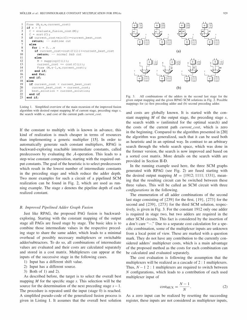
Fig. 3. All combinations of the adders in the second last stage for thegiven output mapping and the given RPAG SCM solutions in Fig. 2. Possiblemappings for (a) first preceding adder and (b) second preceding adder.
and costs are globally known. It is started with the con-stant mapping M of the output stage, the preceding stage s,the search width w (unlimited for the optimal search) andthe costs of the current path current_cost, which is zeroin the beginning. Compared to the algorithm presented in [20]the algorithm was generalized, such that it can be used bothas heuristic and in an optimal way. In contrast to an arbitrarysearch through the whole search space, which was done inthe former version, the search is now improved and based ona sorted cost matrix. More details on the search width areprovided in Section II-D.
In the running example used here, the three SCM graphsgenerated with RPAG (see Fig. 2) are fused starting withthe desired output mapping M = {1912; 1111; 1331}, mean-ing that the resulting circuit can be switched between thesethree values. This will be called an SCM circuit with threeconfigurations in the following.
The enumeration of all adder combinations of the secondlast stage consisting of {239} for the first, {19}, {273} for thesecond and {239}, {273} for the third SCM solution, respec-tively, is given in Fig. 3. For the constant 1912 only one adderis required in stage two, but two adders are required in theother SCM circuits. This fact is considered by the insertion ofa don’t care “−.” Due to a separate cost calculation for a spe-cific combination, some of the multiplexer inputs are unknownfrom a local point of view. These are marked with a questionmark. They do not have any contribution to the currently con-sidered adders’ multiplexer costs, which is a main advantageof the proposed method as the costs for each combination canbe calculated and evaluated separately.
The cost evaluation is following the assumption that themultiplexers will be realized as a cascade of 2 : 1 multiplexers.Thus, N − 1 2 : 1 multiplexers are required to switch betweenN configurations, which leads to a contribution of each usedmultiplexer input of
costMUX = N − 1
N. (2)
As a zero input can be realized by resetting the succeedingregister, these inputs are not considered as multiplexer inputs,

930 IEEE TRANSACTIONS ON COMPUTER-AIDED DESIGN OF INTEGRATED CIRCUITS AND SYSTEMS, VOL. 36, NO. 6, JUNE 2017
TABLE ICOST MATRIX FOR STAGE 2 FUSION OF THE GIVEN EXAMPLE
Fig. 4. Result of combining 239, 19, 239 and −, 273, 273 as precedingadders.
as our implementation targets pipelined implementations.The multiplexer cost for each mapping is stored in a mul-tidimensional cost matrix C (line 3 in Listing 1). The costmatrix for the combinations of the current stage can be foundin Table I in a 2-D representation. For example, the first entryin the first row (1.33) corresponds to the leftmost mapping inFig. 3(a) in which two multiplexer inputs, each with a costMUXof 2
3 are used.To get a valid solution a selection of one mapping for
the first preceding adder in Fig. 3(a) will directly force theselection of the corresponding mapping for the second adderin Fig. 3(b) or reduces the selectable possibilities for otheradders in a more general case. This means each valid map-ping solution for a specific stage consists of selections witha unique row and column index. Thus, finding the cheapestmapping solution M for a specific stage reduces to finding thevalid solution with the lowest sum of costs. An example forsuch a selection is given in Fig. 4. It corresponds to the high-lighted selection in Table I with a total cost contribution of1.33 + 0.67 = 2 2 : 1 multiplexers.
The cheapest solution for a specific stage is not necessarilythe best overall choice as it affects the costs in the precedingstages. So, to find the optimal solution, a full search over allpossibilities is necessary. The search space can be illustratedas a decision tree, which consists of the decision itself as nodeand the cost of the decision as edge. An example for this canbe found in Fig. 5, which shows a decision tree representationfor the second stage fusion decisions of Table I.
Each branch of the tree is a valid mapping solution forthe specific stage which can be chosen as output mapping forthe preceding stage (line 12 in Listing 1). Each branch corre-sponds to a recursive call of Fuse() in line 14 of Listing 1.Thus, to get the full search space, a different decision treefor the preceding stage has to be added recursively for eachstage’s output mapping until the input stage is reached. As the
Fig. 5. Part of the decision tree for the second stage fusion.
cost matrix C is sorted in line 4 of Listing 1 the algorithmfollows the best cost solutions first. In the case of equalcost solutions, the first solution found with these costs, ischosen as the cheapest one. The full decision tree for ourexample can be found in Fig. 6 and can be generated bysetting w to ∞.
As shown in the complexity analysis in the next section, thefull search for the optimal solution can be very time consum-ing for larger problems as the number of combinations growsfactorial with the number of adders Ks in one stage and expo-nential with the number of configurations N. Nevertheless,the memory consumption is moderate for the presented algo-rithm, as only the local environment has to be stored, which isthe currently optimized branch. Moreover, irrelevant branches,which are too expensive anyway, can be pruned whenever thecurrently best cost value is exceeded. This is why the search isstarted with the locally best solution, which already finds goodsolutions in the first iterations. It is executed in a branch-and-bound way, which stops searching a branch if the total costsexceed the current global minimum costs. Besides the nor-mal branch-and-bound method (see Listing 1, lines 9 and 10),denoted as cut in the decision tree in Fig. 7, an additionalpruning criterion is added (see Listing 1, lines 5 and 6). Thesum of minimum values of each row in the cost table is alower bound of costs which can be added by the consideredstage. If this minimum added to the current costs is largerthan the global minimum, the whole subtree can be pruned,denoted as stcut. The best resulting reconfigurable single con-stant multiplier solution of the running example is shown inFig. 1. It corresponds to the leftmost branch in the decisiontree of Figs. 6 and 7.
C. Complexity Consideration: Analysis of the Search Space
As the presented optimal PAG fusion algorithm has to tra-verse the full search space, its complexity, i.e., the number of

MÖLLER et al.: RECONFIGURABLE CONSTANT MULTIPLICATION FOR FPGAs 931
Fig. 6. Full decision tree for the example with costs for each decision, best total costs (light gray) and worse total costs (dark gray).
possible solutions and branches to find them, is an importantissue.
1) Number of Solutions: One key measure is the numberof possible solutions to combine the adders in one stage. Ndenotes the number of configurations while the number ofadders in the considered stage s of the input adder trees is Ks.The total number of adder combinations which are possible is(Ks!)N . As the arrangement of the combinations itself does notmatter, it can be ignored during the enumeration of solutions.As there are Ks! ways to arrange the combinations, the totalnumber of solutions Ls for a specific stage’s s subtree is
Ls = (Ks!)N
Ks!= (Ks!)
N−1. (3)
In the example decision tree of Fig. 6, L1 = L2 = 2(3−1) = 4,which corresponds to the gray nodes in each subtree, as wehave two nodes to fuse and three configurations in each stage.
2) Number of Decisions: In order to evaluate the run-timeof the algorithm the number of decisions D, which is equal tothe number of nodes in the decision tree, is important. Thisnumber depends on the possible solutions Ms for the subtreesand the possibilities to reach them. For one stage’s s subtreethe number of decisions is calculated as
Ds = Ls
Ks−1∑
j=0
(1
j!
)N−1
︸ ︷︷ ︸≤e (Euler Number)
. (4)
In the example decision tree of Fig. 6, D1 = D2 = 4(1(3−1) +1(3−1)) = 8, which corresponds to the white nodes for each
subtree. Note that, although the sum consists of a factorial andan exponential part, it has an upper limit of e (Euler number).
For the whole decision tree the total number of decisionsis the sum of decisions in each stage. This is the number ofsubtrees (solutions of the preceding stages) multiplied by thenumber of subtree decisions
D =S−1∑
i=1
Di
i−1∏
j=1
Lj. (5)
This means for our running example that though we have only16 possible solutions, 40 (= 8·1+8·4·1) decisions are requiredto build them.
The equation for the total number of decisions (5) showsthat the search space to find the optimal solution grows at leastfactorial with the number of adders per stage K and expo-nential with the number of configurations N, as it contains aproduct term of the Ls [see (3)]. For larger benchmarks thisis not applicable, not even when branch-and-bound is applied.Therefore a heuristic is needed, to reduce the considered searchspace.
D. PAG Fusion for Larger Problems
The presented PAG fusion approach is able to find validsolutions for pipelined RSCM and RMCM adder graphs.Finding the optimal solution cannot be guaranteed for largeproblems, which can lead to drastic time consumption. Thus,a heuristic to find a close-to-optimal solution with control-lable time consumption is required. Finding a good heuristicis not trivial, as it is not clear which strategy is appropriate

932 IEEE TRANSACTIONS ON COMPUTER-AIDED DESIGN OF INTEGRATED CIRCUITS AND SYSTEMS, VOL. 36, NO. 6, JUNE 2017
Fig. 7. Reduced search space of wsearch = 1 for the given example.
for the present search space. An analysis of the search spaceof PAG fusion showed, that selecting branches with low costsin the local decision phase, raises the likelihood to find opti-mal or close-to-optimal solutions. Thus, the heuristic presentedhere works by limiting the number of branches to the oneswhich are most likely to be included in the optimal solution.These are the cheapest solutions in each search tree stage.The search branches are limited by the so called search widthwsearch. The value of wsearch specifies the number of additionalbranches which are searched with the locally best solution.Thus, the search strategy is a modified breadth-first search andis related to the beam search strategy [24]. Within the mean-ing of this definition the initial greedy search of the algorithmhas a search width of wsearch = 0. As described earlier inSection II-B the decision for the next path to follow in thedecision tree is made by using a cost matrix for each consid-ered subtree in each stage. For the heuristic these cost matricesare sorted (see line 4 in Listing 1), to be able to quickly accessthe wsearch+1 best paths. When a path is selected, this selectionequals the desired output mapping for the previous stage. Forthat previous stage the cost matrix is evaluated in the sameway. This provides a very plain and fast method to reducethe search space. Note that the described branch-and-boundcuts can also be applied within the heuristic, which has thepotential to further speed up the search. Especially the sub-tree cut (stcut), which was already explained in Section II-B
is now very easy to perform due to the sorted use of the costmatrix within the heuristic. An example for the search spaceof wsearch = 1 can be found in Fig. 7. The branch-and-boundcuts are denoted as cut, while the subtree cuts are denotedas stcut. Only eight instead of 40 decisions are needed com-pared to the full search for this rather small example to finda good—in this case the best—solution. This heuristic pro-vides an easy way to directly control the run-time and offersthe possibility to realize larger switchable coefficient sets forsingle and MCM.
E. Exploiting Ternary Adders
Adders with three inputs (ternary adders) can significantlyreduce the number of operations in a PAG generated bythe RPAG heuristic [21] and thus, reduce the required hard-ware. Support for ternary adders is given in recent Alteraand Xilinx FPGAs, namely Arria I, II, V, 10, Stratix II-V,and Virtex 5-7 [22], [23]. That is why the fusion of suchPAGs using three-input adders was also integrated into PAGfusion, taking the implementation available at OpenCores [25].The target is to reduce the number of operations and with itthe required multiplexer inputs. Instead of the two operationsa + b and a − b each adder in the adder graph is now able toimplement a+b+c, a−b+c, a+b−c, or a−b−c. The costevaluation and the decision for a specific stage’s mapping wasadapted to this circumstance. This includes an extension of thedata structure to provide nodes with three inputs. Special carehas to be taken, when nodes with two and nodes with threeinputs are fused. Here an addition with 0 has to be providedfor the input, which is unused in one circuit. This leads to anadditional degree of freedom, when selecting the node’s inputmapping and evaluating a mapping’s costs. Another exten-sion had to be provided in the fusion of subtractors. In thetwo-input adder case it is possible to map all negative inputsto the same input resulting in a subtractor instead of a switch-able adder–subtractor. This is not always possible in the threeinput adder case (a − b − c). However, the swapping of inputsto get the best possible solution was adapted for the ternaryadder cases (a − b + c, a + b − c), in which a swapping canhelp to reduce the required resources. All these adaptions areleading to a larger complexity for the consideration of inputsin these steps. Nevertheless, the overall run-time is supposedto be reduced, as the number of adders Ks per stage is reduceddue to the operation reduction shown by Kumm et al. [21].
III. LOW LEVEL OPTIMIZATIONS
A. Multiplexer Mapping
As multiplexers are used to switch between the differentconstants, their mapping to the target FPGA should be asgood as possible. This can be achieved by using the explicitresources provided in Xilinx Virtex 5-7 slices [26]. In the caseof the used Virtex 6 FPGA, our VHDL code generator pro-duces the optimal mapping using Primitives [26] and methodsdescribed in [27]. This results in a resource optimized mul-tiplexer implementation. The gain of this implementation canbe seen in Fig. 8, which shows the lookup table (LUT) con-sumption of the default mapping achieved by Xilinx ISE 13.4

MÖLLER et al.: RECONFIGURABLE CONSTANT MULTIPLICATION FOR FPGAs 933
Fig. 8. Required LUTs for 1-bit x:1 multiplexer. ISE solution (gray) andimprovement by Primitive usage [26] with methods described in [27] (black).
Fig. 9. Realization of switchable adder/subtractor on Xilinx Virtex 5-7 slices.
(gray) as well as the improved solution by using Primitivesand the resource optimal mapping [27] (black when better,otherwise equal to ISE mapping). The operating frequency isnot shown, due to the fact that only one up to three slices arerequired, which leads to frequency estimations between 770and 1.300 MHz, which is unrealistic for a final design, as thereshould be more limiting parts elsewhere. In 16 of the 31 casesone LUT per bit can be saved. That is why the inclusion ofthis mapping as operator into our FloPoCo-based [28] VHDLgenerator is part of this paper.
B. Switchable Adder Subtractor Mapping
The fusion of adders with subtractors leads to the require-ment of switchable adder/subtractors in which the input that issubtracted can be either input a or input b. The proposed real-ization of the switchable adder/subtractors on Xilinx Virtex 5-7slices can be found in Fig. 9. The realization is done using asingle LUT to provide the correct carry input and the followingLUTs to provide an XOR of the inverted or noninverted inputs,which builds a full adder together with the slice’s carry logic.The inputs are inverted when required by an additional XORof each input with the corresponding subtraction flag sa or sb.The subtraction flag sa or alternatively sb has to be set to 1 ifa or b, respectively, should be subtracted. The case in whichsa and sb are both 1 is not supported by the given implementa-tion. Using the described switchable adder/subtractor togetherwith the optimized multiplexer implementation helps to fur-ther reduce the required slice resources. In our experimentswe observed cases, in which the more general VHDL imple-mentation needed more than twice as many LUTs. So whena switchable adder subtractor is required more than 50% of
Fig. 10. Comparison of the required slices of the heuristic with differentsearch widths and optimal solution (dashed lines).
slice resources can be saved in the best case with the proposedimplementation.
IV. RESULTS
This section provides synthesis results to highlight theadvantages of the proposed method. For all experiments thesame VHDL code generator which is based on the FloPoColibrary [28] was used to create synthesizable VHDL code.VHDL code was generated with identical settings and mappedto a Virtex 6 FPGA (xc6vlx75t-2ff484-2) using Xilinx ISEv13.4. The proposed algorithms’ input graphs to be fused werecreated using the RPAG heuristic. The source code of RPAGand of the proposed method is available online as open sourcewithin the PAGSuite [16].
A. Quality of the Heuristic
In order to evaluate the quality of the heuristic, an SCMbenchmark for 2 to 14 configurations, each consisting of 100constant sets using randomly generated constants uniformlydistributed between 1 and 216 − 1 was created. In this exper-iment, optimal solutions were generated to have a baselinefor the heuristic results. In addition to that, solutions usingthe heuristic with different search widths for all benchmarksets were generated. A direct comparison of the average sliceutilization of the optimal PAG fusion and the heuristic for con-stant sets with 2 to 6 configurations can be found in Fig. 10. Itshows the required slices for the different search widths andthe optimal solutions with dashed lines. It can be observedthat a search width of only 64 leads to solutions close to theoptimal solution for the RSCM benchmark sets with up tosix configurations. The maximum operating frequency of allsolutions is distributed equally between 443 and 469 MHz.The average run-time for a width of 64 in this experiment iscompared in Table II. It can be observed that a longer run-time of the optimal algorithm leads to an increased speedupfor the heuristic. At the same time, the area degradation of theheuristic is smaller than 1%. This encourages the use of theheuristic for larger numbers of outputs as required for RMCM

934 IEEE TRANSACTIONS ON COMPUTER-AIDED DESIGN OF INTEGRATED CIRCUITS AND SYSTEMS, VOL. 36, NO. 6, JUNE 2017
TABLE IICOMPARISON OF THE AVERAGE RUN-TIME OF THE HEURISTIC
TO THE OPTIMAL METHOD AND AVERAGE AREA
OVERHEAD OF THE HEURISTIC SOLUTION
problems, which have a much larger complexity due to a largeradder count per stage.
B. Comparison to DAG Fusion
This section shows a comparison of the proposed algo-rithm to the DAG fusion algorithm [17] which also relies onthe fusion of adder graphs. The same benchmark as for theheuristic classification was used. Using this benchmark PAGswith the proposed PAG fusion heuristic as well as pipelinedand non-PAGs with DAG fusion using the available SPIRALsource code [13] were generated. The pipelined DAG fusionresults were obtained by inserting registers after each adder,subtractor, adder/subtractor, multiplexer, and correspondingpipeline balancing registers. Pipelined results for DAG fusionare needed for a fair comparison of the slice utilization andperformance evaluation. The proposed algorithm was executedwith a search width of 64 as motivated in the last section.DAG fusion was executed with a restricted mode provided inthe DAG fusion code when the run-time exceeded 3 h (typ-ically needed for cases with more than nine configurations).The results for the required slices after place and route and themaximum clock frequency can be found in Fig. 11. Note thateach data point is an average value of 100 constant sets. Asa baseline, a 16 × 16 bit CoreGen [29] soft-core multiplier(LUT-based implementation) with the same pipeline depthas our solutions together with distributed RAM to store thecoefficients is shown in Fig. 11. For the pipelined implemen-tations it can be observed that the proposed algorithm has alower slice utilization than DAG fusion in all cases. Comparedto DAG fusion, the proposed method provides a slice reductionof 9% on average when 2-input adders are considered and 26%on average when ternary adders are considered. The resulting2-input adder circuits can be run at nearly the same maximumclock frequency as the pipelined DAG fusion circuits and theCoreGen reference. Due to pipelining, the proposed methodand pipelined DAG fusion have a similar critical path, whichcan be found in the adders or in the multiplexers with varyingsize. For the ternary adders there is a performance degrada-tion of about 39% on average which was also reported byKumm et al. [21]. The nonpipelined DAG fusion results arein some cases better than the pipelined 2-input and ternaryadder results, but the maximum clock frequency is up to 5times slower. This clearly shows the necessity of pipeliningon FPGAs. The comparison between the DAG fusion resultsand the results of the proposed method also show that an
Fig. 11. Comparison of the required slices (top) and the maximum clockfrequency (bottom) for the proposed method and DAG fusion [17].
optimization which considers all configurations in a singlerun leads to better results. In general, it can be seen thatthe proposed method is valuable for up to four configurationsin the 2-input adder case and up to six configurations in theternary adder case, when the required slices are considered.For more configurations, the soft-core multiplier implementa-tion by CoreGen provides the solution which requires the leastresources. For ASICs, DAG fusion proved to be valuable forup to 19 coefficient RSCM (see [17, Table II]). This appearsto be a maximum gap between the optimized adder imple-mentation and a generic multiplier. This has to be of coursesmaller for FPGAs. For this small gap, which is a relevantfield for many applications, the proposed heuristic can generatesolutions with significantly lower resource consumption andsimilar performance. When only RSCM is considered, optimalsolutions are possible, when about half an hour of run-time isfeasible. But the heuristic is unconditionally required to enableshift-add-based reconfigurable MCM, especially with manyoutputs, which is required, e.g., for run-time reconfigurableFIR filters.
C. Reconfigurable Multiple Constant Multiplication
When reconfigurable MCM is considered, it can again becompared to the CoreGen soft-core multiplier with RAMfor the coefficients. To have more than one output, multiple

MÖLLER et al.: RECONFIGURABLE CONSTANT MULTIPLICATION FOR FPGAs 935
Fig. 12. Comparison of RMCM and tRMCM to a CoreGen soft-coremultiplier + RAM.
CoreGen multipliers, and coefficient RAMs are used. A bench-mark for five different MCM cases (2, 4, 6, 8, and 10 outputs),each with 2, 4, 6, 8, and 10 configurations, consisting of 50constant sets per case using randomly generated constants uni-formly distributed between 1 and 216 − 1 was created. Thesearch width was again set to 64. The results of the 2-inputand 3-input adder implementations compared to CoreGenmultipliers can be found in Fig. 12.
It can be seen that the CoreGen soft-core multiplier imple-mentation is better for 6 or more configurations in the 2-inputadder case and 8 or more configurations in the ternary addercase. Below these numbers of configurations, up to 75% ofthe resources can be saved, when the proposed reconfigurableshift and add-based implementation is preferred, which is upto 750 slices in the 10 output RMCM case. Note that withoutthe heuristic only the results for two outputs and two configu-rations could have been generated optimally within a run-timelimit of 3 h. MCM solutions normally have more adders ineach stage, which leads to a much larger search space andthus a much larger run-time. Using the heuristic with its con-trollable search width, raises the solvable problem size andthereby enables the application domain of RMCM for theproposed fusion algorithm. For the application domains givenin the introduction [1]–[5], 2 to 6 MCM configurations are
TABLE IIICOMPARISON OF A SINGLE FILTER MIRZAEI10_41 WITH
Bx = 16 BIT USING ICAP RECONFIGURATION, CFGLUTMETHODS, THE PROPOSED PAG FUSION HEURISTIC
AND COREGEN MULTIPLIERS
common, which is the range of the proposed heuristic. Up to75% of slice resources can be saved compared to a genericmultiplier.
D. Comparison to Other Reconfiguration Approaches
If the presented multiplexer-based switchable MCM iscompared in the context of reconfigurable circuits, the recon-figuration time is an important factor. The presented approachhas a reconfiguration time of only one clock cycle which isabout 2–3 ns for the mapped and routed designs. To com-pare our method to other reconfiguration approaches, a 41tap benchmark FIR filter (MIRZAEI10_41 [30]) was used.This benchmark was already used in prior work [31], tocompare internal configuration access port (ICAP) reconfig-uration of Xilinx FPGAs and two logic based reconfigurationapproaches. In the benchmark the original filter was extendedto a run-time reconfigurable FIR filter by designing addi-tional different FIR filters with the same length as the originalbenchmark filter and an input word size of 16 bit. These wereoptimized by using RPAG [14] and can be reconfigured viaICAP. Alternatively, the benchmark set was realized using thetwo logic-based reconfiguration approaches (FIR DA and FIRLUT). In the FIR DA approach the FIR filters were realizedusing Distributed Arithmetic [32] with a LUT-based imple-mentation and were made reconfigurable by using run-timeconfigurable 5-input LUTs in Xilinx Virtex FPGAs. The FIRLUT approach is based on the constant (k) coefficient mul-tiplier method KCM [33], in which a constant multiplier isbuilt by several smaller LUT multipliers, whose shifted out-puts are finally added. Reconfiguration was again achievedby using run-time configurable 5-input LUTs in Xilinx VirtexFPGAs. These have a configuration time of 32 clock cycles,leading to a reconfiguration time of about 61 to 66 ns inthe analyzed filters. The presented PAG fusion heuristic canbe used to generate the multiplication of switchable filtercoefficients (RMCM) with the input of a transposed FIR filter,which are then followed by structural adders. The results forthe previous work and results for PAG fusion RMCM FIR fil-ters for 2 to 5 configurations (conf.) are listed in Table III. Inthis case the number of configurations corresponds to the num-ber of different FIR filter coefficient sets. The ICAP resourceconsumption and maximum clock frequency are noted as arange as the applied RPAG optimization heavily depends onthe numeric coefficient values. In addition, a FIR filter using

936 IEEE TRANSACTIONS ON COMPUTER-AIDED DESIGN OF INTEGRATED CIRCUITS AND SYSTEMS, VOL. 36, NO. 6, JUNE 2017
CoreGen multipliers together with RAM was evaluated. It canbe seen that the resulting circuits of the proposed method pro-vide the fastest reconfiguration time with a better resourceconsumption for 2 to 4 configurations. The large increasein slices from 4 to 5 configurations can be directly tracedback to the increase of LUT costs for the 5-input multiplex-ers (see Fig. 8). For 5 to 10 configurations it depends on therequired reconfiguration time, if the reconfigurable FIR filterusing distributed arithmetic or LUT multipliers together withreconfigurable LUTs or the ICAP implementation should beused. An implementation with CoreGen multipliers is onlyvaluable when very fast reconfiguration times and at the sametime a large number of configurations are required.
E. DSP Block Usage Considerations
On modern FPGAs, DSP blocks in combination with RAMfor the coefficients can be used instead of the proposed run-time reconfigurable constant multiplication. If limited quantityof DSP blocks is not a problem, each of the 16 ×16 bit mul-tipliers of reported cases could be replaced by one DSP blockand two slices for the coefficient RAM. For multiplicationword sizes larger than 18 bit, more than one DSP blockwould be required for Xilinx FPGAs. A comparison of theusage of DSP blocks to the proposed slice-based method canbe done by relating the two types of resources (DSP blocksand slices) according to their relative availability, referenc-ing their utilization ratio [15]. Alternatively, the chip areaconsumed by the resources can be related [35]. However,neither of the two methods addresses the frequent require-ment to select the smallest, hence cheapest, possible FPGAthe design fits into. Usually, in a complete design other partsare competing for DSP resources in digital signal processingapplications [36], [37]. For such cases a tradeoff must be avail-able. This is provided by the proposed slice based run-timereconfigurable constant multiplier implementation.
V. CONCLUSION
This paper presented a new heuristic to generate pipelinedrun-time reconfigurable constant multipliers based on an opti-mal algorithm. The heuristic was motivated by a complexityconsideration of the search space. With the heuristic problemswith a larger size become solvable. An extensive bench-mark evaluation showed superiority over previous work, as wecould show a 9%–26% slice reduction on average. Additionalextensions to the algorithm were presented which furtherreduce the slice consumption of the resulting solutions. Thesewere the support of ternary adders, and optimized multiplexerand switchable adder/subtractor mapping. Finally, it could beshown by RMCM and FIR filter experiments that the heuris-tic is raising the solvable problem size and the applicationdomain of the proposed fusion method. Compared to otherreconfiguration approaches our method provides the fastestreconfiguration time with a low resource consumption for alimited number of configurations. The source code of theproposed method is available online as open source within thePAGSuite project [16] to increase reproducibility and provideit for future research.
ACKNOWLEDGMENT
The authors would like to acknowledge the work ofDipl.-Math. E. Lerche from the University of Kassel whoprovided some nice hints for the complexity considerations.
REFERENCES
[1] S. S. Demirsoy, I. Kale, and A. G. Dempster, “Reconfigurable multiplierblocks: Structures, algorithm and applications,” Circuits Syst. SignalProcess., vol. 26, no. 6, pp. 793–827, 2007.
[2] L. Aksoy, P. Flores, and J. Monteiro, “Multiplierless design of foldedDSP blocks,” ACM Trans. Design Autom. Electron. Syst., vol. 20, no. 1,Nov. 2014, Art. no. 14.
[3] P. Lowenborg and H. Johansson, “Minimax design of adjustable-bandwidth linear-phase FIR filters,” IEEE Trans. Circuits Syst. I, Reg.Papers, vol. 53, no. 2, pp. 431–439, Feb. 2006.
[4] M. Garrido, F. Qureshi, and O. Gustafsson, “Low-complexity multi-plierless constant rotators based on combined coefficient selection andshift-and-add implementation (CCSSI),” IEEE Trans. Circuits Syst. I,Reg. Papers, vol. 61, no. 7, pp. 2002–2012, Jul. 2014.
[5] M. Faust, O. Gustafsson, and C.-H. Chang, “Reconfigurable multipleconstant multiplication using minimum adder depth,” in Proc. 44thAsilomar Conf. Signals Syst. Comput. Conf. Rec., Pacific Grove, CA,USA, Nov. 2010, pp. 1297–1301.
[6] U. Meyer-Baese, J. Chen, C. H. Chang, and A. G. Dempster, “A com-parison of pipelined RAG-n and DA FPGA-based multiplierless filters,”in Proc. IEEE Asia Pac. Conf. Circuits Syst. (APCCAS), Singapore,Dec. 2006, pp. 1555–1558.
[7] P. Cappello and K. Steiglitz, “Some complexity issues in digital signalprocessing,” IEEE Trans. Acoust. Speech Signal Process., vol. 32, no. 5,pp. 1037–1041, Oct. 1984.
[8] A. G. Dempster and M. D. Macleod, “Constant integer multiplicationusing minimum adders,” IEE Proc. Circuits Devices Syst., vol. 141,no. 5, pp. 407–413, Oct. 1994.
[9] O. Gustafsson, A. G. Dempster, and L. Wanhammar, “Extended resultsfor minimum-adder constant integer multipliers,” in Proc. IEEE Int.Symp. Circuits Syst. (ISCAS), vol. 1. Scottsdale, AZ, USA, 2002,pp. I-73–I-76.
[10] J. Thong and N. Nicolici, “A novel optimal single constant multiplicationalgorithm,” in Proc. ACM/IEEE 47th Design Autom. Conf. (DAC),Anaheim, CA, USA, Jun. 2010, pp. 613–616.
[11] D. R. Bull and D. H. Horrocks, “Primitive operator digital filters,” IEEProc. G Circuits Devices Syst., vol. 138, no. 3, pp. 401–412, Jun. 1991.
[12] Y. Voronenko and M. Püschel, “Multiplierless multiple constantmultiplication,” ACM Trans. Algorithms, vol. 3, no. 2, May 2007,Art. no. 11.
[13] (2016). SPIRAL-Project. [Online]. Available: http://www.spiral.net[14] M. Kumm, P. Zipf, M. Faust, and C.-H. Chang, “Pipelined adder graph
optimization for high speed multiple constant multiplication,” in Proc.IEEE Int. Symp. Circuits Syst. (ISCAS), Seoul, South Korea, May 2012,pp. 49–52.
[15] M. Kumm, “Multiple constant multiplication optimizations for field pro-grammable gate arrays,” Ph.D. dissertation, Digit. Technol. Group, Elect.Eng. Comput. Sci., Univ. Kassel, Kassel, Germany, 2016.
[16] (2016). PAGSuite Project Website. [Online]. Available:http://www.uni-kassel.de/go/pagsuite
[17] P. Tummeltshammer, J. C. Hoe, and M. Puschel, “Time-multiplexedmultiple-constant multiplication,” IEEE Trans. Comput.-Aided DesignIntegr. Circuits Syst., vol. 26, no. 9, pp. 1551–1563, Sep. 2007.
[18] J. Chen and C.-H. Chang, “High-level synthesis algorithm for thedesign of reconfigurable constant multiplier,” IEEE Trans. Comput.-Aided Design Integr. Circuits Syst., vol. 28, no. 12, pp. 1844–1856,Dec. 2009.
[19] K. Möller, M. Kumm, B. Barschtipan, and P. Zipf, “Dynamically recon-figurable constant multiplication on FPGAs,” in Proc. WorkshopMethoden Und Beschreibungssprachen Zur Modellierung undVerifikation Von Schaltungen Und Systemen (MBMV), Böblingen,Germany, 2014, pp. 159–169.
[20] K. Möller, M. Kumm, M. Kleinlein, and P. Zipf, “Pipelined reconfig-urable multiplication with constants on FPGAs,” in Proc. 24th Int. Conf.Field Program. Logic Appl. (FPL), Munich, Germany, 2014, pp. 1–6.
[21] M. Kumm, M. Hardieck, J. Willkomm, P. Zipf, and U. Meyer-Baese,“Multiple constant multiplication with ternary adders,” in Proc. 23rd Int.Conf. Field Program. Logic Appl. (FPL), Porto, Portugal, Sep. 2013,pp. 1–8.
MÖLLER et al.: RECONFIGURABLE CONSTANT MULTIPLICATION FOR FPGAs 937
[22] G. Baeckler, M. Langhammer, J. Schleicher, and R. Yuan, “Logic cellsupporting addition of three binary words,” U.S. Patent 7 565 388, 2009.
[23] J. M. Simkins and B. D. Philofsky, “Structures and methods for imple-menting ternary adders/subtractors in programmable logic devices,” U.S.Patent 7 274 211, Mar. 2006.
[24] F. Hayes-Roth, M. Fox, G. Gill, and D. J. Mostow, “Speech under-standing systems: Summary of results of the five-year research effort,”Dept. Comput. Sci., Carnegie-Mellon Univ., Pittsburgh, PA, USA,Tech. Rep. 1529, 1977.
[25] (2016). OpenCores. [Online]. Available: http://opencores.org/project,ternaryadder
[26] Virtex-6 FPGA Configurable Logic Block User Guide UG364 (v1.2),Xilinx Inc., San Jose, CA, USA, Tech. Rep. UG364 (v1.2), Feb. 2012.
[27] K. Chapman, “Multiplexer design techniques for datapath performancewith minimized routing resources,” Xilinx Inc., San Jose, CA, USA,Tech. Rep. XAPP522 (v1.2), Oct. 2014.
[28] F. de Dinechin and B. Pasca, “Designing custom arithmetic data pathswith FloPoCo,” IEEE Des. Test Comput., vol. 28, no. 4, pp. 18–27,Jul./Aug. 2011.
[29] “LogiCORE IP Multiplier,” Xilinx Inc., San Jose, CA, USA,Tech. Rep. DS255 (v11.2), Mar. 2011.
[30] (2016). FIRsuite. [Online]. Available: http://www.firsuite.net[31] M. Kumm, K. Möller, and P. Zipf, “Dynamically reconfigurable FIR
filter architectures with fast reconfiguration,” in Proc. 8th Int. WorkshopReconfigurable Commun. Centric Syst. Chip (ReCoSoC), Darmstadt,Germany, 2013, pp. 1–8.
[32] A. Croisier, D. Esteban, M. Levilion, and V. Riso, “Digital filter forPCM encoded signals,” U.S. Patent 3 777 130, 1973.
[33] K. Chapman, “Constant coefficient multipliers for the XC4000E,” XilinxAppl. Note, San Jose, CA, USA, Tech. Rep. XAPP054 (v1.1), Dec. 1996.
[34] M. Kumm, K. Möller, and P. Zipf, “Reconfigurable FIR filter usingdistributed arithmetic on FPGAs,” in Proc. IEEE Int. Symp. CircuitsSyst. (ISCAS), Beijing, China, 2013, pp. 2058–2061.
[35] M. J. Beauchamp, S. Hauck, K. D. Underwood, and K. S. Hemmert,“Architectural modifications to enhance the floating-point performanceof FPGAs,” IEEE Trans. Very Large Scale Integr. (VLSI) Syst., vol. 16,no. 2, pp. 177–187, Feb. 2008.
[36] T. H. Pham, S. A. Fahmy, and I. V. McLoughlin, “Low-power correla-tion for IEEE 802.16 OFDM synchronization on FPGA,” IEEE Trans.Very Large Scale Integr. (VLSI) Syst., vol. 21, no. 8, pp. 1549–1553,Aug. 2013.
[37] F. de Dinechin and B. Pasca, “Large multipliers with fewer DSP blocks,”in Proc. Int. Conf. Field Program. Logic Appl., Prague, Czech Republic,2009, pp. 250–255.
Konrad Möller received the B.Eng. degree in elec-trical engineering from the University of AppliedSciences Fulda, Fulda, Germany, in 2011, and theM.Sc. degree in electrical engineering from theUniversity of Kassel, Kassel, Germany, in 2012,where he is currently pursuing the Ph.D. degree withthe Digital Technology Group.
His current research interests include dynamicallyreconfigurable computing on field-programmablegate arrays (FPGAs), model-based design forFPGAs, and other methodologies for high levelsynthesis for FPGAs.
Martin Kumm (M’12) received the Dipl.-Ing.degree in electrical engineering from the FuldaUniversity of Applied Sciences, Fulda, Germany,and the Technical University of Darmstadt,Darmstadt, Germany, in 2003 and 2007, respec-tively, and the Ph.D. (Dr.-Ing.) degree from theUniversity of Kassel, Kassel, Germany, in 2015.
From 2003 to 2009, he was with GSI Darmstadt,Darmstadt, Germany, researching on digital RFcontrol systems for particle accelerators. Hiscurrent research interests include digital signal
processing, filter circuits, and computer-aided design, all in the context offield-programmable gate arrays and very large scale integration technology.
Marco Kleinlein is currently pursuing the B.Eng.degree with the University of Kassel, Kassel,Germany.
Since 2012, he has been a Research Assistantwith the Digital Technology Group, Universityof Kassel. His current research interests includedynamic reconfigurable computing and algorithmsfor automated code generation for hardware andsoftware designs.
Peter Zipf (M’05) received the B.A. degree in com-puter science from the University of Kaiserslautern,Kaiserslautern, Germany, in 1994, and the Ph.D.(Dr.-Ing.) degree from the University of Siegen,Siegen, Germany, in 2002.
He was a Post-Doctoral Researcher withthe Department of Electrical Engineering andInformation Technology, Darmstadt University ofTechnology (Technische Universität Darmstadt),Darmstadt, Germany, until 2009. He is currently theChair for Digital Technology with the University of
Kassel, Kassel, Germany. His current research interests include dynamicallyreconfigurable computing, embedded-system and system-on-chip designs, aswell as design methodologies and CAD tools for reconfigurable systems.