IEEE TRANSACTIONS ON ANTENNAS AND …timormel/index_files/PBparamPub.pdf · applying a...
8
IEEE TRANSACTIONS ON ANTENNAS AND PROPAGATION, VOL. 59, NO. 10, OCTOBER 2011 3855 Time-Dependent Tilted Pulsed-Beams and Their Properties Yakir Hadad and Timor Melamed Abstract—Novel time-dependent wavepacket equation and its pulsed field solutions are obtained by utilizing a non-orthog- onal coordinate system which is a priori matched to the field’s planar linearly-delayed pulsed localized aperture distributions. These waveobjects that serve as the building blocks for var- ious time-dependent beam-expansion schemes, are termed tilted pulsed-beams. Iso-axial pulsed-beams are parameterized in term of beam-widths, waist-locations, collimation-lengths, wave-front radii of curvature, and other features. Emphasis is placed on a direct time-domain derivation. A numerical example is presented in which the enhanced accuracy of the tilted pulsed-beams over the conventional (orthogonal coordinates) ones in the well-collimated zone is demonstrated. Index Terms—Electromagnetic propagation, parabolic wave equation, pulsed beams. I. INTRODUCTION P ARABOLIC wave equation (PWE) methods are a major tool for analysis and synthesis of scalar or electromagnetic fields [1]–[3]. Solutions of the PWE are subject to boundary conditions which are obtained by matching the field aperture distribution on a given surface to the PWE model. For prob- lems in which the aperture distribution is given over a surface that is perpendicular to the initial paraxial direction, it may be conveniently matched to the PWE model. PWE methods can be used for obtaining beam waveobjects that serve as the building blocks for several beam-type ex- pansion schemes by utilizing the beam’s mutual spectral and spatial localization. Locality considerations have been utilized for solving beam-type waveobjects propagation in generic media profiles such as inhomogeneous [4]–[7], anisotropic [8]–[15], for time-dependent pulsed-beams, in dispersive media [16]–[20] and for inverse scattering applications [21], [22]. Beam solutions are significant for beam-type (phase-space) expansions of scalar or electromagnetic fields such as Gabor-based expansions [23], [24], continuous spectrum representations [24]–[26] or for the frame-based field expan- sions [27]–[31]. Exact beam-type expansions require beam solutions that match localized aperture planar distributions. In these solutions the boundary plane over which the aperture Manuscript received November 26, 2010; revised February 24, 2011; ac- cepted March 14, 2011. Date of publication August 08, 2011; date of current version October 05, 2011. The authors are with the Department of Electrical and Computer Engi- neering, Ben-Gurion University of the Negev, Beer Sheva 84105, Israel (e-mail: [email protected]). Digital Object Identifier 10.1109/TAP.2011.2163784 field distribution is given is generally not perpendicular to the beam-axis. Since such waveobjects serve as the basic building blocks for different pulsed beam expansions, it is an important task to parameterize them in order to calibrate these expansion schemes and utilize them in different scattering scenarios [32]–[41] Recently, a novel time-harmonic PWE was obtained by applying a non-orthogonal coordinate system which is a priori matched to localized aperture field distributions [7], [42], [43]. Localized solutions to this equation that exactly match linearly-phased Gaussian aperture distributions were termed tilted Gaussian beams. In the present contribution we extend these results and intro- duce in Section III a time-dependent wavepacket equation in non-orthogonal coordinates and derive in Section IV its local- ized field solutions that are termed tilted pulsed-beams (tilted PBs). The properties and parameterization of these waveobjects are explored in Section V as well as the additional wave phe- nomena associated with applying a non-orthogonal coordinate system. Finally in Section VI we present a numerical analysis of the accuracy of the tilted PBs in comparison to the conventional PBs and demonstrate that the tilted PBs are more accurate over a wide range of propagation regimes and parameters. II. FORMULATION We seek for asymptotically-exact PB solutions, , to the 3D scalar wave equation (1) in the half-space, where denotes the medium wave-speed. Here is the conventional Cartesian coordinate frame with denoting the transverse coordinates. A. Analytic Signals In order to gain flexibility in the derivation, particularly when evanescent spectra are involved, it is convenient to use the analytic signal representation (more details are given in Sections V-A and V-B). Given a real signal that is defined for real , the corresponding analytic signal is defined by the convolution integral (2) 0018-926X/$26.00 © 2011 IEEE
Transcript of IEEE TRANSACTIONS ON ANTENNAS AND …timormel/index_files/PBparamPub.pdf · applying a...

IEEE TRANSACTIONS ON ANTENNAS AND PROPAGATION, VOL. 59, NO. 10, OCTOBER 2011 3855
Time-Dependent Tilted Pulsed-Beams andTheir PropertiesYakir Hadad and Timor Melamed
Abstract—Novel time-dependent wavepacket equation and itspulsed field solutions are obtained by utilizing a non-orthog-onal coordinate system which is a priori matched to the field’splanar linearly-delayed pulsed localized aperture distributions.These waveobjects that serve as the building blocks for var-ious time-dependent beam-expansion schemes, are termed tiltedpulsed-beams. Iso-axial pulsed-beams are parameterized in termof beam-widths, waist-locations, collimation-lengths, wave-frontradii of curvature, and other features. Emphasis is placed on adirect time-domain derivation. A numerical example is presentedin which the enhanced accuracy of the tilted pulsed-beams over theconventional (orthogonal coordinates) ones in the well-collimatedzone is demonstrated.
Index Terms—Electromagnetic propagation, parabolic waveequation, pulsed beams.
I. INTRODUCTION
P ARABOLIC wave equation (PWE) methods are a majortool for analysis and synthesis of scalar or electromagnetic
fields [1]–[3]. Solutions of the PWE are subject to boundaryconditions which are obtained by matching the field aperturedistribution on a given surface to the PWE model. For prob-lems in which the aperture distribution is given over a surfacethat is perpendicular to the initial paraxial direction, it may beconveniently matched to the PWE model.PWE methods can be used for obtaining beam waveobjects
that serve as the building blocks for several beam-type ex-pansion schemes by utilizing the beam’s mutual spectral andspatial localization. Locality considerations have been utilizedfor solving beam-type waveobjects propagation in genericmedia profiles such as inhomogeneous [4]–[7], anisotropic[8]–[15], for time-dependent pulsed-beams, in dispersivemedia [16]–[20] and for inverse scattering applications [21],[22].Beam solutions are significant for beam-type (phase-space)
expansions of scalar or electromagnetic fields such asGabor-based expansions [23], [24], continuous spectrumrepresentations [24]–[26] or for the frame-based field expan-sions [27]–[31]. Exact beam-type expansions require beamsolutions that match localized aperture planar distributions. Inthese solutions the boundary plane over which the aperture
Manuscript received November 26, 2010; revised February 24, 2011; ac-cepted March 14, 2011. Date of publication August 08, 2011; date of currentversion October 05, 2011.The authors are with the Department of Electrical and Computer Engi-
neering, Ben-Gurion University of the Negev, Beer Sheva 84105, Israel(e-mail: [email protected]).Digital Object Identifier 10.1109/TAP.2011.2163784
field distribution is given is generally not perpendicular to thebeam-axis. Since such waveobjects serve as the basic buildingblocks for different pulsed beam expansions, it is an importanttask to parameterize them in order to calibrate these expansionschemes and utilize them in different scattering scenarios[32]–[41]Recently, a novel time-harmonic PWE was obtained by
applying a non-orthogonal coordinate system which is a priorimatched to localized aperture field distributions [7], [42],[43]. Localized solutions to this equation that exactly matchlinearly-phased Gaussian aperture distributions were termedtilted Gaussian beams.In the present contribution we extend these results and intro-
duce in Section III a time-dependent wavepacket equation innon-orthogonal coordinates and derive in Section IV its local-ized field solutions that are termed tilted pulsed-beams (tiltedPBs). The properties and parameterization of these waveobjectsare explored in Section V as well as the additional wave phe-nomena associated with applying a non-orthogonal coordinatesystem. Finally in Section VI we present a numerical analysis ofthe accuracy of the tilted PBs in comparison to the conventionalPBs and demonstrate that the tilted PBs are more accurate overa wide range of propagation regimes and parameters.
II. FORMULATION
We seek for asymptotically-exact PB solutions, , to the3D scalar wave equation
(1)
in the half-space, where denotes the mediumwave-speed. Here is the conventional Cartesiancoordinate frame with denoting the transversecoordinates.
A. Analytic Signals
In order to gain flexibility in the derivation, particularlywhen evanescent spectra are involved, it is convenient to usethe analytic signal representation (more details are given inSections V-A and V-B). Given a real signal that is definedfor real , the corresponding analytic signal is defined by theconvolution integral
(2)
0018-926X/$26.00 © 2011 IEEE
3856 IEEE TRANSACTIONS ON ANTENNAS AND PROPAGATION, VOL. 59, NO. 10, OCTOBER 2011
Here and henceforth, analytic signals are denoted by a brevemark . The limit of the analytic signal on the real -axis isrelated to the real signal by
(3)
where is the Hilbert transform operator, withdenoting Cauchy’s principal value and denoting a temporal
convolution. Therefore the real signal for real is recoveredfrom the analytic signal via . Alternatively theanalytic signal can be obtained by applying a one-sided(positive frequencies) inverse Fourier transform to the spectral(frequency domain) distribution of the real signal . Sincethis paper is concerned with a direct time-domain derivation,this approach is not investigated here.
B. Statement of the Problem
We are aimed at obtaining PB waveobjects that can serveas the building blocks for different time-dependent beam-typefield expansion schemes. These expansion schemes decomposethe field over a spatial-directional-temporal (spectral) lattice ofspectral variables. The propagating elements are PBs that areidentified by their planar aperture field distributions over the
plane, , of the form [26], [28]
(4)
where are the expansion (directional) spectral vari-ables. Throughout this work, all vectors are column vectors andsuperscript denotes the matrix (or the vector) transpose, sothat the linear delay-term in (4) reads . In(4), is a 2 2 complex symmetric matrix with a negativedefinite imaginary part. Here and henceforth, bold lower-caseletters are used to denote vectors, whereas bold capital lettersare used to denote matrices. Note that (4) consists of a local-ized pulsed distribution with a quadratic delay term as well as alinear one that causes the beam to tilt with respect to the aper-ture plane.
III. THE NON-ORTHOGONAL WAVEPACKET EQUATION
We apply here the non-orthogonal local coordinate systemwhich was introduced in [42]. This system is a priori matchedto the aperture field distribution in (4). The spectral variables
(5)
form a unit vector in the direction of the beam-axis
(6)
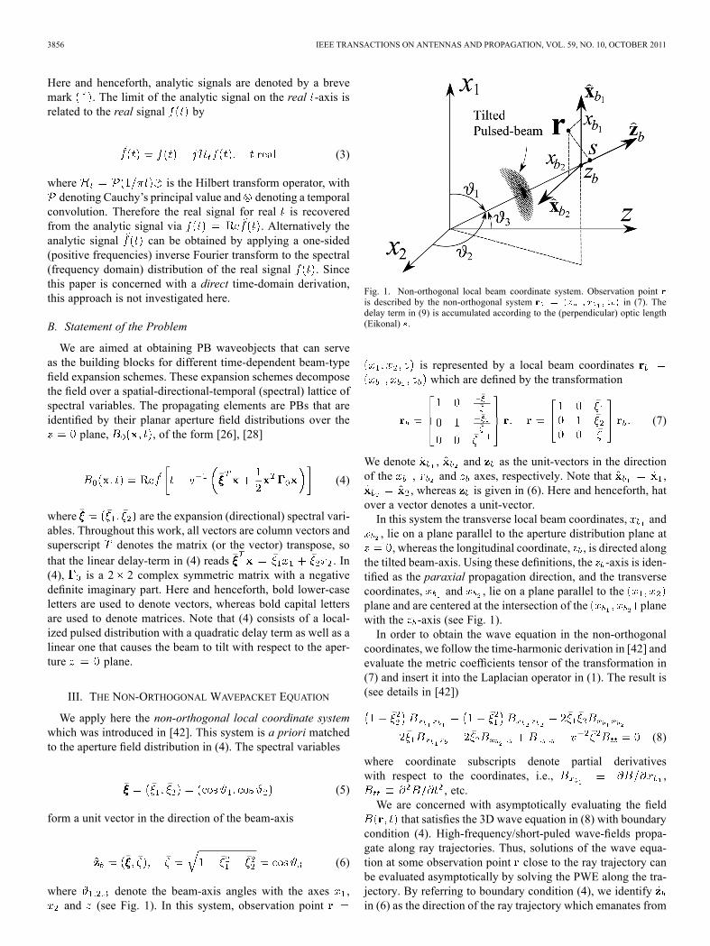
where denote the beam-axis angles with the axes ,and (see Fig. 1). In this system, observation point
Fig. 1. Non-orthogonal local beam coordinate system. Observation pointis described by the non-orthogonal system in (7). Thedelay term in (9) is accumulated according to the (perpendicular) optic length(Eikonal) .
is represented by a local beam coordinateswhich are defined by the transformation
(7)
We denote , and as the unit-vectors in the directionof the , and axes, respectively. Note that ,
, whereas is given in (6). Here and henceforth, hatover a vector denotes a unit-vector.In this system the transverse local beam coordinates, and, lie on a plane parallel to the aperture distribution plane at, whereas the longitudinal coordinate, , is directed along
the tilted beam-axis. Using these definitions, the -axis is iden-tified as the paraxial propagation direction, and the transversecoordinates, and , lie on a plane parallel to theplane and are centered at the intersection of the planewith the -axis (see Fig. 1).In order to obtain the wave equation in the non-orthogonal
coordinates, we follow the time-harmonic derivation in [42] andevaluate the metric coefficients tensor of the transformation in(7) and insert it into the Laplacian operator in (1). The result is(see details in [42])
(8)
where coordinate subscripts denote partial derivativeswith respect to the coordinates, i.e., ,
, etc.We are concerned with asymptotically evaluating the field
that satisfies the 3D wave equation in (8) with boundarycondition (4). High-frequency/short-puled wave-fields propa-gate along ray trajectories. Thus, solutions of the wave equa-tion at some observation point close to the ray trajectory canbe evaluated asymptotically by solving the PWE along the tra-jectory. By referring to boundary condition (4), we identifyin (6) as the direction of the ray trajectory which emanates from

HADAD AND MELAMED: TIME-DEPENDENT TILTED PULSED-BEAMS AND THEIR PROPERTIES 3857
the aperture point . Therefore we assume here thatthe wave field has the following short-pulsed form
(9)
where the Eikonal
(10)
is the projection of the observation vector on the direction ofthe beam-axis . Using the ray-field (9)–(10), we can evaluatethe derivatives in (8)
(11)
and so-forth for all partial derivatives in (8). In (11) all partialderivatives of are taken withrespect to the corresponding argument, i.e., prior to samplingat .Next, following conventional paraxial ray-theory [3]–[5], we
assume that
(12)
By inserting (11) as well as all the other partial derivatives into(8) and neglecting terms according to (12), the wave equation isapproximated by
(13)
Equation (13) is termed here the Non-orthogonal WavepacketEquation (NOWE). Note that by setting(namely ) in (13), the NOWE reduces to thewell-known wavepacket equation in orthogonal coordinates [5].
IV. TILTED PBS
Tilted PBs that are defined by aperture distributions of lin-early-delated pulsed windows of the form in (4) are of highlysignificance as they serve as the building blocks for time-depen-dent beam-type expansions [26], [28]. In this section, we obtainasymptotically-exact expressions for these wavepackets.In view of the aperture field distribution in (4), we are seeking
localized beam solutions of the NOWE and assume a beam-typefield of the form
(14)
where , denotes a complex ampli-tude and the so-called complex curvature matrix is acomplex symmetrical matrix with denoting its thelement so that the argument in (14) is of the quadratic form
. The matrix has anegative definite imaginary part, hence beam-field (14) exhibitsa decay away from the beam-axis. Pulsed beam-fields of theform in (14), which carry aperture localized pulsed distributionsover the tilted plane, are termed here tilted PBs.Next, we insert the PB form in (14) into the NOWE (13). By
setting the coefficients of the temporal derivatives and to
zero for all observation points, we obtain two vector equations.The first equation is a vector Riccati-type equation for ,
(15)
whereas the second equation,
(16)
serves as the amplitude once the Riccati equation in (15)is solved. In (15)–(16) the prime denotes a derivative with re-spect to the argument.The solution of the Riccati equation is [42]
(17)
where is the complex curvature matrix of the aperture fielddistribution over the plane in (4). The beam amplitude,
, is found by inserting (17) into (16). Using a straightfor-ward separation of variables we obtain
(18)
The tilted PB can be written explicitly by using (17) and (18) in(14), and inserting into (9), which yieldswhere
(19)
where
(20)
is given in (10) and is given in (17). Note that PB(19) satisfies the aperture field distribution in (4) exactly. Thistype of PB waveobjects exhibits frequency-independent col-limation (Rayleigh) distance and therefore have been termediso-diffracting [44]. The iso-diffracting feature makes thesewaveobjects highly suitable for UWB radiation representations[25], [27], [28], [45], [46].
V. PARAMETERIZATION OF THE TILTED PB
A. On-Axis Properties
The tilted PB in (19) propagates along the beam-axis that isdefined for a given spectral-variable by , i.e.,
. By separating the field’s amplitude in (18) into its realand imaginary parts,
(21)

3858 IEEE TRANSACTIONS ON ANTENNAS AND PROPAGATION, VOL. 59, NO. 10, OCTOBER 2011
and using the analytic signal limit for real in (3) the on-axisPB field, , is given by
(22)
where denotes the Hilbert transform of . Thus, theon-axis field is composed of a weighting of and its Hilberttransform.Since, according to (17), the real part of increases
linearly with whereas its imaginary part remains constant,the weighting in the far-field (where is large on the scaleof the collimation-lengths) is made according to the real andimaginary parts of . In the special case of an imag-inary aperture curvature matrix where is real and nega-tive, for large values so that the PB on-axis tem-poral shape undergoes a full Hilbert transform from inthe near-field to in the far-field. The temporal, as wellas the spatial off-axis features of the propagating PB in (19), de-pends on the specific choice of the pulse shape and of theaperture complex curvature matrix, .
B. Lorentzian Temporal Dependence
A simple Lorentzian time-dependent pulse-shape is attainedby choosing the analytic signal
(23)
where is a real parameter which models the time-dependentsignal’s temporal pulse length and is the analytic delta-function in the upper half of the complex -plane
(24)
For this pulse-shape the quadratic-Lorentzian aperture field dis-tribution in (4) is given by
(25)
The tilted PB field in the half space is given bywhere
(26)
and is given in (20).
C. Off-Axis Parameterization
We now proceed to examine the properties of the Lorentziantilted PB in (26) for iso-axial waveobjects. This family of PBsis used for expanding some aperture field using radially-sym-metric windows (the parametrization of other tilted PBs can be
obtained in a similar manner). The Iso-axial GBs are charac-terized by a diagonal aperture complex curvature matrix of theform [26], [27], [29]
(27)
where and are real parameters.1) Diagonalization of the Transverse Coordinates: The real
and imaginary parts of the complex iso-axial curvature matrixcan be diagonalized simultaneously by rotating the -axes overconstant -planes by a -independent angle
(28)
Therefore we define new (rotated) transversal coordinateswhich are obtained from via
(29)
Angle is identified as the angle between the -axis and theprojection of the -axis on plane. By inserting (29)with (28) into (17), the quadratic phase in (20) is given by
(30)
By inserting in (28) into (30) with (27) and (17), we find thattakes the from of the diagonal matrix
(31)
for which and are given in (27).In order to parameterize the iso-axial tilted PB field, we sep-
arate the diagonalized complex curvature matrix into itsreal and imaginary parts by denoting
(32)
Then using (31), we obtain
(33)
and
(34)
with
(35)

HADAD AND MELAMED: TIME-DEPENDENT TILTED PULSED-BEAMS AND THEIR PROPERTIES 3859
Finally we separate in (20) into its real and imaginaryparts
(36)
where, using (30) and (32) in (20), we identify
(37)
and
(38)
where and are given in (33) and (34), respectively.The real Lorentzian wave-forms are given by
(39)
and
(40)
where and are given in (37) and (38), respectively. The(real) tilted PB in (26) is obtained by weighting of the wave-forms in (39) and (40) as in (22), i.e.,
(41)
2) Transversal Beam-Widths and Diffraction Angles: Byusing (36) in (37) or (38), one can readily identify asthe paraxial propagation delay along the axis. For a givenobservation point , the beam field in (39) peaks atand its half-amplitude pulse-length and peak-value are givenby and , respectively. The transverse half-amplitudebeam widths of the tilted PB propagator in the principleplanes, , is obtained by solving .Note that the perpendicular beam width in the direction of theprojection of is obtained by multiplying the -width by(cf. Fig. 2). This procedure yields
(42)
where and are given in (35). Using (42) we iden-tify as the collimation-lengths and as the waist-lo-cations with corresponding minimal beam-widths of
at the waists. Note that according to (42), near thewaists where , the beam remains collimated
Fig. 2. Parameterization of the iso-axial tilted PB. The field is sampled overthe plane for the Lorentzian time-dependence in (23). All parametersare normalized with respect to .
whereas far from thewaists the beam spreads in constant diffrac-tion angles of
(43)
in the planes.3) Phase-Front Radii of Curvature: In order to parameterize
the paraxial wavefront delay phenomenology as prescribed bythe field quadratic delay-term in non-orthogonal coordinates, the tilted PB is casted in the paraxialgeometrical optics ray-field canonical form in orthogonal coor-dinates. This procedure has been introduced in [43]. We referthe reader to the results there in which the wave front radii ofcurvature are given by (43).
VI. NUMERICAL EXAMPLE
A. Parameterization
In order to verify the accuracy of the tilted PB parameteriza-tion we present in Fig. 2 the contour lines of andfrom the on-axis peak value of a PB field with a Lorentziantime-dependence. The field is sampled over the planewith field parameters of , and
. The peak on-axis point was set to 0.65 of the colli-mation length away from the waist locations at (i.e.,
) so that the field is sampled at . Thecorresponding wavefront radius of curvature in Section V-C-IIIis , and the transverse beam width in (42)is . One can identify in Fig. 2 that the numericallyevaluated contour line agrees with the theoretically eval-uated beam width and the wave front radius of curvature.
B. Accuracy Analysis
In this section we compare the accuracy of the tilted PBs withthe convectional paraxial PBs which are given in local beam or-thogonal coordinates. The reference solution is evaluated usinga transient plane-wave spectral integration of the aperture fieldin (4).

3860 IEEE TRANSACTIONS ON ANTENNAS AND PROPAGATION, VOL. 59, NO. 10, OCTOBER 2011
1) Tilted PBs: The tilted PBs are given by (26) with the iso-axial curvature matrix in (31).2) Conventional PBs: The convectional paraxial PB that are
corresponding to the aperture field in (4) with the iso-axial aper-ture curvature in (27) are obtained by utilizing the local orthog-onal beam-coordinates, , which are definedfor a given spectral variables , by the rotation transformation
where the rotation matrix is given by [26]
(44)
Here are the spherical angles that define the beam-axisin (6). The conventional PBs for the Lorentzian time-depen-
dence in (23) are given by where[26]
(45)
where
(46)
and is given by
(47)for which and are given in (27).3) Reference Solution: The reference solution is evaluated
using a transient plane-wave integration. The spectral represen-tation of the aperture distribution in (4) with the iso-axial curva-ture in (27) and the Lorentzian time-dependence in (23) is givenby [26]
(48)
where are the plane-wave (directional) spectralvariables, , and denotes the lon-gitudinal spectral normalized wavenumber with and
. In (48), denotes the derivative of the analyticdelta-function in (24), i.e.,
(49)
4) Error Comparison: In this section we compare theaccuracy of the tilted PB in (26) (which is denoted hereas ) to the accuracy of the conventional PB in(45), , both with respect the reference solution
. The 3D fields are evaluated over plane forand for various values of (various tilting) and .
We quantify the accuracy by the norm of the difference ofthe PB and the reference PB over domain where either
Fig. 3. Error of the tilted PBs (solid line) and conventional PBs (dashed line)with respect to the reference solution. The field parameters are ,
, . The sampling time is set so that the PB is centered onvarious locations along the beam-axis . The -location in the horizontal axisis normalized with respect to the collimation length , i.e., .(a) , (b) .
the PB or the reference PB exceeds half of the reference PB’s(absolute) maximum. This domain over plane is denotedby . Thus the relative error is
(50)
where denotes either the tilted PB or the conventional oneand is the area of .The relative errors in dB as a function of the -location for
, 60 in (5) are plotted in Fig. 3(a) and (b), respec-tively. In these figures the tilted PB errors are plotted in solidlines and the conventional PB errors are plotted in dashed lines.The field parameters are , , . Thesampling time is set so that the PB is centered on various loca-tions along the beam-axis . The location is normalized withrespect to the collimation length in (35), so that the well-col-limated regime is characterized by (see (42)).This figure demonstrates that the tilted PB exhibits an about 3–4dB enhanced accuracy in the collimation range for .The error difference decreases as the departure angle becomesperpendicular and for 60 the error difference reduces to about1–1.5 dB.Note that the error of the asymptotic solutions is quit small
(less than ). Nevertheless, the PBs are the buildingblocks of the phase-space beam summation method (as de-scribed in Sections I and II-B). Thus, the overall error which isaccumulated in the summation over the entire 5D spatial-direc-tional-temporal spectral lattice is significantly higher than theaccuracy of a single PB. Taking this into account, the 3–4 dBenhanced accuracy can be regarded as significant. Furthermore,beam-type expansions are usually tuned such that the scatteringof a single spectral PB occurs in the well-collimated zone werethe tiled PBs exhibit an enhanced accuracy. It should be notedthough that in some practical applications the choice of is atradeoff between collimation and spatial localization in relationto the size of the details in the medium [47], [48].In order to evaluate the error for well collimated PBs we plot
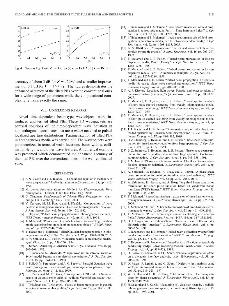
in Fig. 4 the errors as in Fig. 3 with , andfor , in Fig. 4(a) and (b), respec-
tively. By inserting and into (43), we eval-uate the corresponding diffraction angles to be and 0.2radians, respectively. Here the tilted PB exhibits an enhanced
HADAD AND MELAMED: TIME-DEPENDENT TILTED PULSED-BEAMS AND THEIR PROPERTIES 3861
Fig. 4. Same as Fig. 3 with for (a) , (b) .
accuracy of about 3 dB for and a smaller improve-ment of 0.7 dB for . The figures demonstrates theenhanced accuracy of the tilted PBs over the conventional onesfor a wide range of parameters while the computational com-plexity remains exactly the same.
VII. CONCLUDING REMARKS
Novel time-dependent beam-type waveobjects were in-troduced and termed tilted PBs. These 3D wavepackets areparaxial solutions of the time-dependent wave equation innon-orthogonal coordinates that are a priori matched to pulsedlocalized aperture distributions. Parametrization of tilted PBsin homogeneous media was carried out. The waveobjects wereparameterized in terms of waist-locations, beam-widths, colli-mation-lengths, and other wave features. A numerical examplewas presented which demonstrated the enhanced accuracy ofthe tilted PBs over the conventional ones in the well-collimatedzone.
REFERENCES
[1] S. N. Vlasov and V. I. Talanov, “The parabolic equation in the theory ofwave propagation,” Radiophys. Quantum Electron., vol. 38, pp. 1–12,1995.
[2] M. Levys, Parabolic Equation Methods for Electromagnetic WavePropagation. London, U.K.: Inst. Elect. Eng., 2000.
[3] C. Chapman, Fundamentals of Seismic Wave Propagation. Cam-bridge, UK: Cambridge Univ. Press, 2004.
[4] V. Ĉerveny, M. M. Popov, and I. Pŝenĉik, “Computation of wavefields in inhomogeneous media—Gaussian beam approach,” Geophys.J. Roy. Aerosp. Soc., vol. 70, pp. 109–128, 1982.
[5] E. Heyman, “Pulsed beam propagation in an inhomogeneous medium,”IEEE Trans. Antennas Propag., vol. 42, pp. 311–319, 1994.
[6] T. Melamed, “Phase-space Green’s functions for modeling time-har-monic scattering from smooth inhomogeneous objects,” J.Math. Phys.,vol. 45, pp. 2232–2246, 2004.
[7] Y. Hadad and T.Melamed, “Tilted Gaussian beam propagation in inho-mogeneous media,” J. Opt. Soc. Am. A, vol. 27, pp. 1840–1850, 2010.
[8] S. Y. Shin and L. B. Felsen, “Gaussian beams in anisotropic media,”Appl. Phys., vol. 5, pp. 239–250, 1974.
[9] R. Simon, “Anisotropic Gaussian beams,” Opt. Commun., vol. 46, pp.265–269, 1983.
[10] R. Simon and N. Mukunda, “Shape-invariant anisotropic GaussianSchell-model beams: A complete characterization,” J. Opt. Soc. Am.A, vol. 15, pp. 1361–1370, 1998.
[11] E. Poli, G. V. Pereverzev, and A. G. Peeters, “Paraxial Gaussian wavebeam propagation in an anisotropic inhomogeneous plasma,” Phys.Plasmas, vol. 6, pp. 5–11, Jan. 1999.
[12] L. I. Perez and M. T. Garea, “Propagation of 2D and 3D Gaussianbeams in an anisotropic uniaxial medium: Vectorial and scalar treat-ment,” Optik, vol. 111, pp. 297–306, 2000.
[13] I. Tinkelman and T. Melamed, “Gaussian beam propagation in genericanisotropic wavenumber profiles,” Opt. Lett., vol. 28, pp. 1081–1083,2003.
[14] I. Tinkelman and T. Melamed, “Local spectrum analysis of field prop-agation in anisotropic media, Part I—Time-harmonic fields,” J. Opt.Soc. Am. A, vol. 22, pp. 1200–1207, 2005.
[15] I. Tinkelman and T. Melamed, “Local spectrum analysis of field prop-agation in anisotropic media, Part II—Time-dependent fields,” J. Opt.Soc. Am. A, vol. 22, pp. 1208–1215, 2005.
[16] A. G. Khatkevich, “Propagation of pulses and wave packets in dis-persive gyrotropic crystals,” J. Appl. Spectrosc., vol. 46, pp. 203–207,1987.
[17] T. Melamed and L. B. Felsen, “Pulsed beam propagation in losslessdispersive media, Part I: Theory,” J. Opt. Soc. Am. A, vol. 15, pp.1268–1276, 1998.
[18] T. Melamed and L. B. Felsen, “Pulsed beam propagation in losslessdispersive media, Part II: A numerical example,” J. Opt. Soc. Am. A,vol. 15, pp. 1277–1284, 1998.
[19] T. Melamed and L. B. Felsen, “Pulsed beam propagation in dispersivemedia via pulsed plane wave spectral decomposition,” IEEE Trans.Antennas Propag., vol. 48, pp. 901–908, 2000.
[20] A. P. Kiselev, “Localized light waves: Paraxial and exact solutions ofthe wave equation (a review),” Opt. Spectrosc., vol. 102, pp. 603–622,2007.
[21] T. Melamed, E. Heyman, and L. B. Felsen, “Local spectral analysisof short-pulse-excited scattering from weakly inhomogenous media:Part I-forward scattering,” IEEE Trans. Antennas Propag., vol. 47, pp.1208–1217, 1999.
[22] T. Melamed, E. Heyman, and L. B. Felsen, “Local spectral analysisof short-pulse-excited scattering from weakly inhomogeneous media:Part II-inverse scattering,” IEEE Trans. Antennas Propag., vol. 47, pp.1218–1227, 1999.
[23] J. J. Maciel and L. B. Felsen, “Systematic study of fields due to ex-tended apertures by Gaussian beam discretization,” IEEE Trans. An-tennas Propag., vol. 37, pp. 884–892, 1989.
[24] B. Z. Steinberg, E. Heyman, and L. B. Felsen, “Phase space beam sum-mation for time-harmonic radiation from large apertures,” J. Opt. Soc.Am. A, vol. 8, pp. 41–59, 1991.
[25] B. Z. Steinberg, E. Heyman, and L. B. Felsen, “Phase space beam sum-mation for time dependent radiation from large apertures: Continuousparametrization,” J. Opt. Soc. Am. A, vol. 8, pp. 943–958, 1991.
[26] T.Melamed, “Phase-space beam summation: A local spectrum analysisfor time-dependent radiation,” J. Electromag. Waves Appl., vol. 11, pp.739–773, 1997.
[27] A. Shlivinski, E. Heyman, A. Boag, and C. Letrou, “A phase-spacebeam summation formulation for ultra wideband radiation,” IEEETrans. Antennas Propag., vol. 52, pp. 2042–2056, 2004.
[28] A. Shlivinski, E. Heyman, and A. Boag, “A pulsed beam summationformulation for short pulse radiation based on windowed Radontransform (WRT) frames,” IEEE Trans. Antennas Propag., vol. 53,pp. 3030–3048, 2005.
[29] T. Melamed, “Exact Gaussian beam expansion of time-harmonic elec-tromagnetic waves,” J. Electromag. Waves Appl., vol. 23, pp. 975–986,2009.
[30] T. Melamed, “TE and TM beam decomposition of time-harmonic elec-tromagnetic waves,” J. Opt. Soc. Am. A, vol. 28, pp. 401–409, 2011.
[31] T. Melamed, “Pulsed beam expansion of electromagnetic aperturefields,” Progr. Electromagn. Res., vol. PIER 114, pp. 317–332, 2011.
[32] D. J. Hoppe and Y. Rahmat-Samii, “Gaussian beam reflection at adielectric-chiral interface,” J. Electromag. Waves Appl., vol. 6, pp.603–624, 1992.
[33] R. Ianconescu and E. Heyman, “Pulsed beam diffraction by a perfectlyconducting wedge. Exact solution,” IEEE Trans. Antennas Propag.,vol. 42, pp. 1377–1385, 1994.
[34] E. Heyman and R. Ianconescu, “Pulsed beam diffraction by a perfectlyconducting wedge. Local scattering models,” IEEE Trans. AntennasPropag., vol. 43, pp. 519–528, 1995.
[35] O. Pascal, F. Lemaitre, and G. Soum, “Paraxial approximation effecton a dielectric interface analysis,” Ann. Telecommun., vol. 51, pp.206–218, 1996.
[36] O. Pascal, F. Lemaitre, and G. Soum, “Dielectric lens analysis usingvectorial multimodal Gaussian beam expansion,” Ann. Telecommun.,vol. 52, pp. 519–528, 1997.
[37] W. B. Dou and E. K. N. Yung, “Diffraction of an electromagneticbeam by planar structures,” J. Electromag. Waves Appl., vol. 15, pp.1539–1549, 2001.
[38] H. Sakurai and S. Kozaki, “Scattering of a Gaussian beam by a radiallyinhomogeneous dielectric sphere,” J. Electromag.Waves Appl., vol. 15,pp. 1673–1693, 2001.

3862 IEEE TRANSACTIONS ON ANTENNAS AND PROPAGATION, VOL. 59, NO. 10, OCTOBER 2011
[39] H. T. Anastassiu and P. H. Pathak, “Closed form solution for three-di-mensional reflection of an arbitrary Gaussian beam by a smooth sur-face,” Radio Science, vol. 37, pp. 1–8, 2002.
[40] M. Katsav and E. Heyman, “A beam summation representation for3-D radiation from a line source distribution,” IEEE Trans. AntennasPropag., vol. 56, pp. 602–605, 2008.
[41] M. Katsav and E. Heyman, “Gaussian beams summation representa-tion of half plane diffraction: A full 3-D formulation,” IEEE Trans.Antennas Propag., vol. 57, pp. 1081–1094, 2009.
[42] Y. Hadad and T. Melamed, “Non-orthogonal domain parabolic equa-tion and its Gaussian beam solutions,” IEEE Trans. Antennas Propag.,vol. 58, pp. 1164–1172, 2010.
[43] Y. Hadad and T. Melamed, “Parameterization of the tilted Gaussianbeam waveobjects,” Progr. Electromagn. Res., vol. PIER 102, pp.65–80, 2010.
[44] E. Heyman and T. Melamed, “Certain considerations in aperture syn-thesis of ultrawideband/short-pulse radiation,” IEEE Trans. AntennasPropag., vol. 42, pp. 518–525, 1994.
[45] E. Heyman and T. Melamed, “Space-time representation of ultra wide-band signals,” in Advances in Imaging and Electron Physics. TheNetherlands: Elsevier, 1998, vol. 103, pp. 1–63.
[46] T. Melamed, “Time-domain phase-space Green’s functions for inho-mogeneous media,” in Ultrawideband/Short Pulse Electromagnetics6, E. L. Mokole, M. Kragalott, K. R. Gerlach, M. Kragalott, and K. R.Gerlach, Eds. New York: Springer-Verlag, 2007, pp. 56–63.
[47] G. Gordon, E. Heyman, and R. Mazar, “A phase-space Gaussian beamsummation representation of rough surface scattering,” J. Acoust. Soc.Am., vol. 117, pp. 1911–1921, 2005.
[48] G. Gordon, E. Heyman, and R. Mazar, “Phase space beam summationanalysis of rough surface waveguide,” J. Acoust. Soc. Am., vol. 117,pp. 1922–1932, 2005.
Yakir Hadad was born in Beer Sheva, Israel, in1984. He received the B.Sc. (summa cum laude) andM.Sc. (summa cum laude) degrees in electrical andcomputer engineering from Ben-Gurion Universityof the Negev, Israel, in 2005 and 2008, respectively.Currently, he is a Ph.D. student at the Department
of Physical-Electronics, School of Electrical Engi-neering, Tel-Aviv University, Israel. His main fieldsof interest are asymptotic methods, artificial mate-rials and analytic modeling in electromagnetics.
TimorMelamedwas born in Tel-Aviv, Israel, in Jan-uary 1964. He received the B.Sc. degree (magna cumlaude) in electrical engineering in 1989 and the Ph.D.degree in 1997, both from Tel-Aviv University.From 1996 to 1998, he held a postdoctoral posi-
tion at the Department of Aerospace and MechanicalEngineering, Boston University. Currently, he iswith the Department of Electrical and ComputerEngineering, Ben-Gurion University of the Negev,Israel. His main fields of interest are analytic tech-niques in wave theory, transient wave phenomena,
inverse scattering and electrodynamics.