IEEE TRANSACTIONS ON AEROSPACE AND ... - …nrl.northumbria.ac.uk/34116/1/A Trajectory-Driven...
14
Citation: Cao, Yue, Han, Chong, Zhang, Xu, Kaiwartya, Omprakash, Zhuang, Yuan, Aslam, Nauman and Dianati, Mehrdad (2018) A Trajectory-Driven Opportunistic Routing Protocol for VCPS. IEEE Transactions on Aerospace and Electronic Systems, 54 (6). pp. 2628-2642. ISSN 0018-9251 Published by: IEEE URL: https://ieeexplore.ieee.org/document/8338142/ <https://ieeexplore.ieee.org/document/8338142/> This version was downloaded from Northumbria Research Link: http://nrl.northumbria.ac.uk/34116/ Northumbria University has developed Northumbria Research Link (NRL) to enable users to access the University’s research output. Copyright © and moral rights for items on NRL are retained by the individual author(s) and/or other copyright owners. Single copies of full items can be reproduced, displayed or performed, and given to third parties in any format or medium for personal research or study, educational, or not-for-profit purposes without prior permission or charge, provided the authors, title and full bibliographic details are given, as well as a hyperlink and/or URL to the original metadata page. The content must not be changed in any way. Full items must not be sold commercially in any format or medium without formal permission of the copyright holder. The full policy is available online: http://nrl.northumbria.ac.uk/policies.html This document may differ from the final, published version of the research and has been made available online in accordance with publisher policies. To read and/or cite from the published version of the research, please visit the publisher’s website (a subscription may be required.)
Transcript of IEEE TRANSACTIONS ON AEROSPACE AND ... - …nrl.northumbria.ac.uk/34116/1/A Trajectory-Driven...

Citation: Cao, Yue, Han, Chong, Zhang, Xu, Kaiwartya, Omprakash, Zhuang, Yuan, Aslam, Nauman and Dianati, Mehrdad (2018) A Trajectory-Driven Opportunistic Routing Protocol for VCPS. IEEE Transactions on Aerospace and Electronic Systems, 54 (6). pp. 2628-2642. ISSN 0018-9251
Published by: IEEE
URL: https://ieeexplore.ieee.org/document/8338142/ <https://ieeexplore.ieee.org/document/8338142/>
This version was downloaded from Northumbria Research Link: http://nrl.northumbria.ac.uk/34116/
Northumbria University has developed Northumbria Research Link (NRL) to enable users to access the University’s research output. Copyright © and moral rights for items on NRL are retained by the individual author(s) and/or other copyright owners. Single copies of full items can be reproduced, displayed or performed, and given to third parties in any format or medium for personal research or study, educational, or not-for-profit purposes without prior permission or charge, provided the authors, title and full bibliographic details are given, as well as a hyperlink and/or URL to the original metadata page. The content must not be changed in any way. Full items must not be sold commercially in any format or medium without formal permission of the copyright holder. The full policy is available online: http://nrl.northumbria.ac.uk/policies.html
This document may differ from the final, published version of the research and has been made available online in accordance with publisher policies. To read and/or cite from the published version of the research, please visit the publisher’s website (a subscription may be required.)

IEEE TRANSACTIONS ON AEROSPACE AND ELECTRONIC SYSTEMS 1
A Trajectory-Driven Opportunistic Routing Protocolfor VCPS
Yue Cao, Member, IEEE, Chong Han, Xu Zhang, Omprakash Kaiwartya, Member, IEEE, Yuan Zhuang, NaumanAslam, Member, IEEE and Merhard Dianati, Senior Member, IEEE
Abstract—By exploring sensing, computing and communica-tion capabilities on vehicles, Vehicular Cyber-Physical Systems(VCPS) are promising solutions to provide road safety andtraffic efficiency in Intelligent Transportation Systems (ITS).Due to high mobility and sparse network density, VCPS couldbe severely affected by intermittent connectivity. In this paper,we propose a Trajectory-Driven Opportunistic Routing (TDOR)protocol, which is primarily applied for sparse networks, e.g.,Delay/Disruption Tolerant Networks (DTNs). With geographicrouting protocol designed in DTNs, existing works primarilyconsider the proximity to destination as a criterion for next-hop selections. Differently, by utilizing GPS information of on-board vehicle navigation system to help with data transmission,TDOR selects the relay node based on the proximity to trajectory.This aims to provide reliable and efficient message delivery, i.e.,high delivery ratio and low transmission overhead. TDOR ismore immune to disruptions, due to unfavorable mobility ofintermediate nodes. Performance evaluation results show TDORoutperforms well known opportunistic geographic routing proto-cols, and achieves much lower routing overhead for comparabledelivery ratio.
Index Terms—VCPS, Sparse Networks, DTNs, Trajectory.
I. INTRODUCTION
With continuously increasing attention on transiting infor-mation systems from the pure cyber space to a hybrid cyber-physical space, Vehicular Cyber-Physical Systems (VCPS) [1]aim to integrate computing/communication capabilities intoIntelligent Transportation Systems (ITS). It supports variousapplications [2], including road safety improvement, on-roadinfotainment, and environment estimation, etc.
By applying Vehicle-to-Infrastructure (V2I) and Vehicle-to-Vehicle (V2V) communications [3], existing research workshave shown great gains on achieving delay reduction as wellas reliable data transfer in the physical world, through optimalrouting protocols in Vehicular Ad hoc NETworks (VANETs).Furthermore, with opportunistic routing, the nodal mobility isable to improve the coverage of network. This inspires fruitfulexchanges of speed/location information [4], [5], and deliversdata to the “sink node” for postprocessing.
In VCPS, the major challenge for V2V communicationcomes from the intermittently disrupted connectivity, normally
Y.Cao; O.Kaiwartya; N.Aslam are with the Department of Computerand Information Sciences, Northumbria University, UK. Email: yue.cao;omprakash.kaiwartya; [email protected]. C.Han is with thePureLifi, UK. Email: [email protected]. X.Zhang is with the Departmentof Computer Science, Xi’an University of Technology, China. Email: [email protected]. Y.Zhuang is with Bluvision Inc., Part of HID Global, US.Email: [email protected]. M.Dianati are with the University of Warwick,UK. Email: [email protected].
due to the short encounter duration between vehicles. As theresearch efforts from Delay/Disruption Tolerant Networking(DTN) routing [6], the communication in VCPS is conductedto a “Store-Carry-Forward (SCF)1” manner. Such SCF-enabledrouting protocols have been intensively studied in literature, asa feasible way to tackle intermittently disrupted connectivitiesin VCPS [7]. As already identified in [6], majority of previousworks aim to capture the topological information (e.g., thenumber of encounters, encounter duration, inter-meeting time,etc) [8]–[12] for message delivery. In sharp contrast, a fewworks [13]–[17] studied how to enable geo-centric approachesto bridge network communication.
GPS has been widely used in ITS. In [18], the use of road-map information for ground vehicles tracking is proposed toenhance vehicles’ position prediction. In contrast to vehicle de-tection and tracking, [19] promotes autonomous car navigationusing road profile. For communication purpose, geographicrouting [20], as originally applied in dense networks, requireseach node to know the location of its own (and also thelocation of destination). Upon this condition, a message isgradually delivered to its destination, referring to messagedelivery under a scenario with high network density. Themessage delivery is generally based on a certain criterion (e.g.,the shortest distance) that is used to select appropriate relaynode. Here, the geometric information including distance,direction as well as moving speed can contribute to variousmetrics [21], [22] for the selection of relay node.
As a closely related approach to geographic routing, Tra-jectory Based Forwarding (TBF) [23] was fundamentally analternative to routing in a dense networks. Essentially, theforwarding path is initialized and formulated as a continuousfunction (a sequence of road topological links), this is differentfrom geographic routing that treats as a discrete set of points(e.g., the coordinates of intermediate nodes). By concept,TBF relays a trajectory-embedded message to the node, ingeographical proximity to the dedicated trajectory. This isdifferent from geographic routing that concerns the proximityto destination (e.g., distance to the destination). Therefore,based on the trajectory fueled by TBF, a trajectory-drivenrouting nature is advanced by greedy decisions.
Different from geographic routing applied in dense networks[20]–[23], the sparse network density (which drives oppor-tunistic communication) inevitably brings challenges to enable
1When a vehicle carries a message while there is no contemporaneous end-to-end path to its destination or even a connectivity to any other vehicle, themessage would be stored, and wait for the upcoming encounter opportunitywith other vehicles to relay the message.
IEEE TRANSACTIONS ON AEROSPACE AND ELECTRONIC SYSTEMS 2
the traditional geographic routing in VCPS. Further to [6] thatidentifies the research vacancy of geographic routing in DTNs,a recent review [24] has identified several challenges arisingfrom network sparseness, with solutions [13]–[17] under theumbrella of geographic routing. In spite of these, in this paperwe investigate trajectory-driven routing, with concerns on theopportunistic communication in VCPS.
Inevitably, enabling TBF for VCPS needs to cater chal-lenges from sparseness of network, as dynamically changedvehicles mobility may deteriorate reliable message delivery(suffering from lower delivery ratio) and increase communi-cation cost (suffering from higher routing overhead). Certainly,there are insufficient vehicle encounters in sparse networks, forwhich the estimation of nodal delivery becomes important.
The aforementioned issues are generally translated as“which are selected as relays”, primarily concerning nodalmobility. Our contributions are as follows:
1) TDOR enables source node to compute a mobility-immuned trajectory towards message destination toguide message delivery. The trajectory is initialized toa) relay the message towards trajectory if the messageis isolated (not geographically close to the trajectory);b) relay the message towards destination by associatingwith the trajectory. Such a trajectory-driven policy cansignificantly reduce redundant routing overhead, whichbenefits from the logic that messages will not be re-played to nodes that are isolated from the trajectory.(e.g., nodes tend to move away or are currently too faraway from the trajectory)
2) A multi-queueing system is designed, such that themessage with the highest delivery potential is prioritizedfor transmission. This utilizes the knowledge extractedfrom trajectory and vehicles mobility to improve theutilization of transmission bandwidth, given opportunis-tic encounter with limited inter-vehicle communicationduration.
II. RELATED WORKS
Various architectures for VCPS have been proposed inrecent year. A CPS [2] application framework has been sug-gested for provisioning of a generic service to represent, ma-nipulate, and share knowledge across DTNs, without persistentnetwork connectivity. Since the underlying network of VCPSoften suffers more from the intermittent connectivity due tovehicle mobility and sparse network density, the messagedelivery must be reliable against the connectivity disruptions.
In the literature, Direct Delivery (DD) [25] limits onlythe source node to deliver messages. Although this schemeperforms only one times transmission, it is extremely slowas the delivery only happens when the destination is inproximity. Therefore, other proposed works relay messages viathe qualified nodes based on utility metric [13], [26], withoutreplicating any copy of a message. Even if they can achieve afaster delivery than DD, the performance on message deliveryis dramatically degraded in sparse networks. Therefore, usingredundant message copies has been widely investigated, withtwo main branches depending on whether or not to limit thenumber of copies in replicated message delivery.
A. Unlimited Copy-Based Message Delivery
Since Epidemic [27] floods message copies within networks,it only performs well when no contention exists for shared net-work resources like bandwidth and buffer space. In contrary,many previous works further utilize topological utility metrics[8]–[12] to qualify nodes for selected replication, comparedto a few works which utilize geographic utility metrics [14],[15]. To enhance routing efficiency, Delegation Forwarding(DF) [28] enables a message to cache an updated thresholdvalue (initially, it equals to the topological utility metric fordestination), and relays a message copy towards a node (with abetter utility metric than this cached threshold). As applied inDelegation Geographic Routing (DGR) [15], if without usingDF, a node does not keep a threshold value and certainly themessage carrier does not update this value after it encountersa better quality node. While if with DF, a node will raise thisthreshold value to the quality of a better candidate node, andfurther uses this threshold value for relay node selection. Thus,with the increase of its level, the replication chance of messagecarrier is expected to be decreased, which means the numberof copies duplicated for a message will be reduced.
B. Limited Copy-Based Message Delivery
It is valid for previous works in this branch, that whena number of nodes in the network are sufficiently mobile,replicating a message with a limited number of copies isable to achieve an efficient message delivery. Authors in [29]propose Spray-and-Wait (SaW) algorithm, in which a copyticket is defined for each message, to control the numberof time a message can be replicated. Considering the het-erogeneous nodal mobility, replicating the limited numberof message copies [30] to better qualified nodes has beeninvestigated. To expedite delivery via topological utility metric,Encounter Based Spraying Routing (EBSR) [12] further relays(but without generating additional copies) each copy. Basedon geographic utility metric and underlying map topology,GeoSpray [16] calculates the Nearest Point (NP) to destinationvia underlying map topology to guide message relay. TheBest Heterogeneity Geographic Relay (TBHGR) [17] furtherdiscusses the influence of heterogeneous nodal mobility.
C. Research Motivation
It should be noted that previous routing schemes [21], [22]been applied to dense VANETs (with concerns on vehiculardensity), however are not necessarily applicable to sparsenetworks. Our focus in this paper is on geographic routingdesigns particularly for sparse networks. As summarized inTABLE I, even though there have been some works addressinggeographic routing in DTNs, by explicitly identifying theresearch vacancy and challenges from network sparseness,none of them is trajectory-driven. In other words, instead ofmaking routing decision based on the proximity to destination,TDOR solves the problem by checking the proximity totrajectory, and further enables cost-efficient message deliveryassociated with the trajectory. This benefits to a significantlylower routing overhead, without degrading message delivery.

IEEE TRANSACTIONS ON AEROSPACE AND ELECTRONIC SYSTEMS 3
TABLE ISUMMARY OF RELATED WORKS
Not Based on Geographic InformationDD [25], Epidemic [27], PROPHET [8], DTLSR [9], RAPID [10], CAMF [12],EBRR/EBSR [11], SaW [29], LSF [30]Based on Geographic Information—Not Trajectory Driven—MOVE [13], AeroRP [26], GSaR [14], DGR [15], GeoSpray [16], TBHGR [17]—Trajectory Driven—TDOR
III. PRELIMINARY
A. System Component
We consider sparse VANETs consisting of a number ofvehicles and fixed destinations. Each vehicle is equipped withGlobal Position System (GPS) and captures its own movementinformation, including current location, moving direction andspeed. The locations of stationary destinations (data collectionpoints) are available at nodes, via already recorded digital maptopology.
A slotted based collision avoidance MAC protocol is appliedfor contention resolution, such that only one connection canbe established between two encountered nodes at each timeslot. Different from those works proposed for dense networks,we expect that in networks that are quite sparse, only a fewvehicles would be close enough each time to compete for thetransmission bandwidth simultaneously.
We consider a unicast application session, where a messageis delivered from the source node to destination node, via thehelp of intermediate relays for delivery. Two vehicles can onlycommunicate when they encounter, i.e., when they are withinthe communication range of each other. We define this asan “encounter opportunity” between them. Due to the sparsenetwork density, the network connectivity is unavailable in amajority of time. The duration from the time when pairwisevehicles move in, until move out of transmission range ofeach other, is defined as “encounter duration”. Although weenvision for delay tolerant based data collection applications,messages are usually with a certain lifetime, namely Time-To-Live (TTL).
B. Overview of TDOR
Digital Map
Message
Relay
Application
Layer
Trajectory
Computing
Message
Management
How to initialize a trajectory
as a reference to guide
routing procedure
Whether an encountered
node is qualified as a relay
Which message is
transmitted given limited
encounter duration
Fig. 1. TDOR System Operation
As illustrated in Fig. 1, the soul of TDOR is driven by theTrajectory Computing Phase. The operation in this phasefurther guides the Message Relaying Phase that happens withan “encounter opportunity”. Next, based on the knowledgeof computed trajectory and certain messages to relay, the
Message Management Phase implements the transmissionprocess within “encounter duration”.
• Trajectory Computing Phase: This is only triggeredonce when the source node sends a message. The sourcenode calculates a trajectory and embeds the computedtrajectory information into the message. This means thereis no need for each node to remember the trajectory of allits carried message, instead can learn from the messageitself. The way to generate a trajectory will be explainedin Section IV-A. Note that each node locally computesits desirable trajectory towards message destination, asoperated in a distributed manner.
• Message Relaying Phase: It is executed by the nodecarrying the message (or a message copy), when itencounters other possible relays. The key is to decidewhether or not an intermediate node would be better tohelp with relaying the message. Detailed selection criteriawill be given in Section IV-B.
• Message Management Phase: Due to the short en-counter duration between vehicles, not all messages canbe successfully transmitted. Hence, it is practical to rankthe messages in order to ensure the one with the highestdelivery potential to get transmitted. The message rankingcriterion is detailed in Section IV-C.
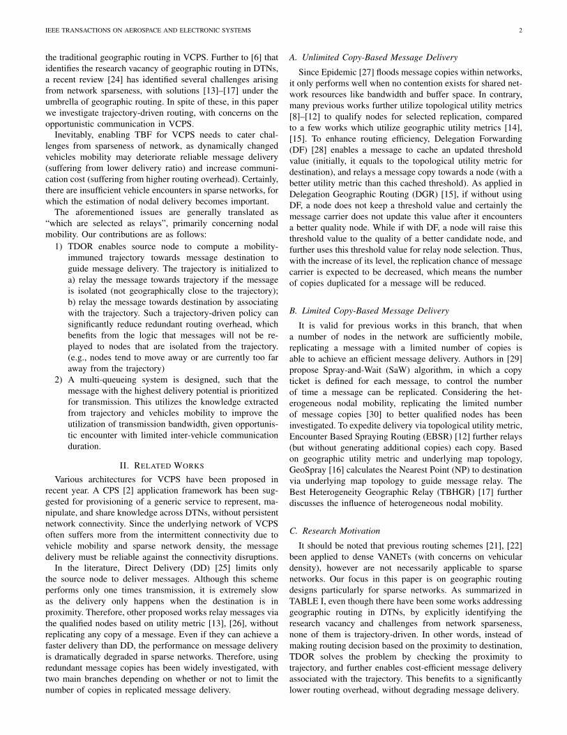
C. Basic Idea - An Example
The basic idea of TDOR is to select a set of relay nodes,which have higher potential to deliver message towards des-tination. For example, the mobility of nodes A,B,C,D andsource node are shown in Fig. 2, where their encounters occuras follows:
1) The source node has a message for delivery, computesthe shortest trajectory (embedded in that certain mes-sage) towards the destination.
2) Although the source node will encounter nodes A andB, only node B is selected as relay. This is becausethe mobility of node B makes forwarding progress(e.g., enabling the message to be in proximity to thedestination) towards destination, while following thetrajectory indicated by the source node. In contrast, asthe mobility of node A will be farther away from thetrajectory, it is not selected as a relay.
3) Given a potential encounter between nodes B and C(e.g., node B is much faster than node C), the messagewould be further relayed to node C, due to the trajectoryproximity (although the latter will not make persistentcontribution to message delivery).
4) Given an encounter between nodes C and D, the latter isselected as a relay, and eventually delivers the messagetowards the destination.
The message delivery process is always driven by the trajec-tory (computed by the source node), as well as instantaneousmobility of selected relay nodes which positively contributeto message delivery. This is different from nature of ourpreviously proposed schemes such as [15], [17]. It is worthynoting that the vehicle encounters do not need to happen at
IEEE TRANSACTIONS ON AEROSPACE AND ELECTRONIC SYSTEMS 4
Destination
Source
A
B
C
D
Trajectory
Computed by
Source
Mobility of A
Mobility of Source
Mobility of B
Mobility of C
Mobility of D
Fig. 2. An Example of Message Relay in TDOR
intersection, wherein under realistic city map a (straight/non-straight) path between two intersections could be formed by aset of coordinates, other than the example in Fig. 2.
In TDOR, the message follows a trajectory established atthe source node, but each intermediate node (carrying themessage or its copy) takes a greedy decision to infer thepossible next hop. In a network where nodal coordinatesare known, the message may be relayed to the node thatis the geographically closest to the desired trajectory. Sincethe location of (stationary) destination is known in advance,the trajectory followed by the message normally consists ofseveral sequent paths, and the routing process reduces tocartesian forwarding.
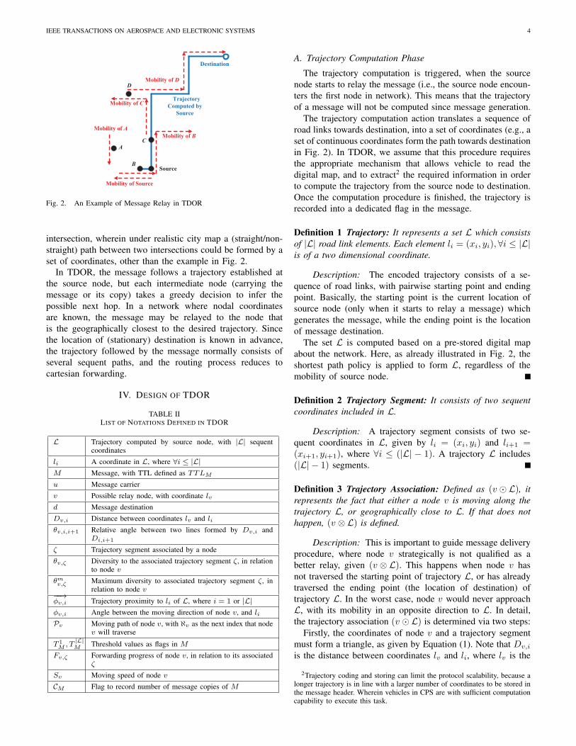
IV. DESIGN OF TDOR
TABLE IILIST OF NOTATIONS DEFINED IN TDOR
L Trajectory computed by source node, with |L| sequentcoordinates
li A coordinate in L, where ∀i ≤ |L|M Message, with TTL defined as TTLM
u Message carrier
v Possible relay node, with coordinate lv
d Message destination
Dv,i Distance between coordinates lv and li
θv,i,i+1 Relative angle between two lines formed by Dv,i andDi,i+1
ζ Trajectory segment associated by a node
θv,ζ Diversity to the associated trajectory segment ζ, in relationto node v
θmv,ζ Maximum diversity to associated trajectory segment ζ, inrelation to node v
−−→ϕv,i Trajectory proximity to li of L, where i = 1 or |L|ϕv,i Angle between the moving direction of node v, and li
Pv Moving path of node v, with ℵv as the next index that nodev will traverse
T 1M , T
|L|M Threshold values as flags in M
Fv,ζ Forwarding progress of node v, in relation to its associatedζ
Sv Moving speed of node v
CM Flag to record number of message copies of M
A. Trajectory Computation Phase
The trajectory computation is triggered, when the sourcenode starts to relay the message (i.e., the source node encoun-ters the first node in network). This means that the trajectoryof a message will not be computed since message generation.
The trajectory computation action translates a sequence ofroad links towards destination, into a set of coordinates (e.g., aset of continuous coordinates form the path towards destinationin Fig. 2). In TDOR, we assume that this procedure requiresthe appropriate mechanism that allows vehicle to read thedigital map, and to extract2 the required information in orderto compute the trajectory from the source node to destination.Once the computation procedure is finished, the trajectory isrecorded into a dedicated flag in the message.
Definition 1 Trajectory: It represents a set L which consistsof |L| road link elements. Each element li = (xi, yi), ∀i ≤ |L|is of a two dimensional coordinate.
Description: The encoded trajectory consists of a se-quence of road links, with pairwise starting point and endingpoint. Basically, the starting point is the current location ofsource node (only when it starts to relay a message) whichgenerates the message, while the ending point is the locationof message destination.
The set L is computed based on a pre-stored digital mapabout the network. Here, as already illustrated in Fig. 2, theshortest path policy is applied to form L, regardless of themobility of source node.
Definition 2 Trajectory Segment: It consists of two sequentcoordinates included in L.
Description: A trajectory segment consists of two se-quent coordinates in L, given by li = (xi, yi) and li+1 =(xi+1, yi+1), where ∀i ≤ (|L| − 1). A trajectory L includes(|L| − 1) segments.
Definition 3 Trajectory Association: Defined as (v ⊙ L), itrepresents the fact that either a node v is moving along thetrajectory L, or geographically close to L. If that does nothappen, (v ⊗ L) is defined.
Description: This is important to guide message deliveryprocedure, where node v strategically is not qualified as abetter relay, given (v ⊗ L). This happens when node v hasnot traversed the starting point of trajectory L, or has alreadytraversed the ending point (the location of destination) oftrajectory L. In the worst case, node v would never approachL, with its mobility in an opposite direction to L. In detail,the trajectory association (v ⊙ L) is determined via two steps:
Firstly, the coordinates of node v and a trajectory segmentmust form a triangle, as given by Equation (1). Note that Dv,i
is the distance between coordinates lv and li, where lv is the
2Trajectory coding and storing can limit the protocol scalability, because alonger trajectory is in line with a larger number of coordinates to be stored inthe message header. Wherein vehicles in CPS are with sufficient computationcapability to execute this task.

IEEE TRANSACTIONS ON AEROSPACE AND ELECTRONIC SYSTEMS 5
Dv,i +Dv,i+1 −Di,i+1 = 0 if node v is moving along L(Dv,i +Dv,i+1 > Di,i+1)
and (Dv,i +Di,i+1 > Dv,i+1)
and (Dv,i+1 +Di,i+1 > Dv,i) else if node v is in proximity to L
(1)
location of node v. Specifically, in Equation (1), the first sub-case implies that node v is currently moving along a trajectorysegment which consists of two sequent coordinates li and li+1,where ∀i ≤ (|L| − 1). The second sub-case implies that nodev is geographically in proximity to the trajectory segment. Inthe latter case, a triangle must be formed, via three coordinateslv , li and li+1 respectively, and the summation of two edgesof triangle must be longer than the third edge).
Secondly, we denote θv,i,i+1 as the angle between two linesformed by Dv,i and Di,i+1, where θv,i,i+1 can be given bycosine theorem:
θv,i,i+1 = arccos
(D2
v,i +D2i,i+1 −D2
v,i+1
2×Dv,i ×Di,i+1
)(2)
Note that, such calculation is the same as θv,i+1,i. In additionto the condition at line 5 of Algorithm 1, the condition(θv,i+1,i <
π2
)and
(θv,i,i+1 ≤ π
2
)must hold true to guarantee
(v ⊙ L). This implies node v should be with forwardingprogress towards the destination. As an example in Fig. 3,(θv,1,2 < π
2
)and
(θv,2,1 < π
2
)are given to determine the
trajectory association of node v.
Dfv,ζ
1stTrajectory Segmentl1
(Starting Point of Trajectory)
Node v
θv,1,22ndTrajectory Segment
3rdTrajectory Segment
θv,2,1
l4(Ending Point of Trajectory)
Dv,ζ
Moving Direction
of Node vθv,ζ
90o
The Trajectory Segment That Node v Associates
Fig. 3. An Example of Trajectory Association
Therefore, by knowing nodal association with the trajectoryL, e.g., (v ⊙ L) or (v ⊗ L), the key of TDOR is to: 1) relaythe message towards a node which is associated with L. 2)let the selected node further relay the message towards thedestination. The trajectory L provides a reference for a set ofrelay nodes that are involved in the Message Relay Phase.
Definition 4 Associated Trajectory Segment: Given that anode is associated with L, it can only be associated with asegment formed by two sequent coordinates of L.
Description: Algorithm 1 presents the logic to deter-mine the associated trajectory segment. Firstly, the operationsbetween lines 2 and 10 find all trajectory segments (formedby sequent locations li and li+1 of L, where ∀i ≤ (|L| − 1),that node v associates), and includes them into a temporaryset H with size |H|.
Algorithm 1 Determine Trajectory Association and ζ1: define a temporary set H2: for (i = 1; i ≤ (|L| − 1); i++) do3: if (Dv,i +Dv,i+1 −Di,i+1 = 0) then4: include li, li+1 into H5: else if (Dv,i +Dv,i+1 > Di,i+1) and (Dv,i +Di,i+1 > Dv,i+1)
and (Dv,i+1 +Di,i+1 > Dv,i) then6: if (θv,i,i+1 ≤ π
2) and (θv,i+1,i <
π2) then
7: include li, li+1 into H8: end if9: end if
10: end for11: if (|H| = 0) then12: return v ⊗ L13: else if (|H| > 2) then14: for (j = 1; j ≤ (|H| − 1); j ++) do15: θj,v,j+1 = (π − θv,j,j+1 − θv,j+1,j)16: end for17: ζ = {lj , lj+1} ← argmax
j≤(|H|−1)(θj,v,j+1)
18: return v ⊙ L19: end if
At line 11, |H| = 0 means there is no trajectory association,as such v⊗L is returned. Otherwise, as presented at line 13, ifthere are more than two coordinates included in H, the angleθj,v,j+1 = (π − θv,j,j+1 − θv,j+1,j) formed by lv, and lj andlj+1 implies the degree of forwarding progress of node v asso-ciated with L. For example, as θ1,v,2 = (π − θv,1,2 − θv,2,1)is given in Fig. 3. At line 17, the trajectory segment throughwhich the node v experiences the largest θj,v,j+1, is deter-mined as the trajectory segment ζ that node v associates. Inthis case, v ⊙ L is returned at line 18.
B. Message Relay Phase
From this section, we denote nodes u and v as the messagecarrier and encountered node (a possible relay node), whilenode d is the message destination. The purpose is to find thenodes which are associated with trajectory.
TDOR Logic: In each encounter between nodes u and v,they will compute their trajectory association related to L.Note that the formulation of L is based on the trajectorycomputation, when node u starts to relay message M . Insummary, the message delivery in TDOR is decoupled intothe following three cases, and detailed in subsections below:
• The ((u⊗L)&(v⊗L)) case, no association: This happenswhen both nodes u and v are not associated with L (e.g.,imagining both nodes u and v are located at left-handside of trajectory in Fig. 3).
• The ((u ⊗ L)&(v ⊙ L)) case, single association: Thishappens only when node v is associated with L, whereasnode u is not.
• The ((u ⊙ L)&(v ⊙ L)) case, double association: Thishappens when both nodes u and v are associated with L.

IEEE TRANSACTIONS ON AEROSPACE AND ELECTRONIC SYSTEMS 6
Inherently, if using traditional geographic routing policies, anode that is geographically closer, or with a faster proximityto the destination is selected most likely. In TDOR, that nodedoes not need to be a relay if it is not associated with L.Such a trajectory-driven message delivery would benefit tolow routing overhead (due to redundant relay) but does notcontribute to successful delivery.
Differentiated Queuing System: Messages processedthrough one of above three cases are differentiated into adedicated queue. This multi-queuing system classifies themessage with certain delivery potential from others.
• The Low Priority Queue (LPQ): This involves the mes-sage to be transmitted to the relay node v which is notassociated with L, given by the ((u⊗L)&(v⊗L)) case.
• The Medium Priority Queue (MPQ): This involves themessage transmission to the relay node v which asso-ciates with L (but does not exactly moving along its asso-ciated trajectory segment). It includes ((u⊗L)&(v⊙L))and ((u⊙ L)&(v ⊙ L)) cases.
• The High Priority Queue (HPQ): This includes messageprocessed by ((u ⊙ L)&(v ⊙ L)) case, only when therelay node v moves along L.
1) The ((u ⊗ L)&(v ⊗ L)) Case: As both nodes u and vare not associated with L, the policy is to find whether node vhas a better potential (depending on its mobility) to associatewith L, as defined by trajectory proximity. Messages involvedfor this case are included in LPQ, as they are isolated to L.
Definition 5 Trajectory Proximity: Given the mobility of n-ode v, the trajectory proximity to li is defined as
−−→ϕv,i, where
i = 1 or |L|. The trajectory proximity happens when node vwill approach either the starting point of L as l1, or its endingpoint l|L|. Here, the calculation of
−−→ϕv,i is given as:
−−→ϕv,i =
|Pv|−1∑k=ℵv
ϕk,i + ϕv,i
|Pv| − ℵv + 1(3)
Description: Here, Pv is a set (with size |Pv| > 1) whichincludes a number of coordinates that node v will traverse. ℵv
is the index of the path segment that node v will traverse alongPv as such ℵv < |Pv|. As an example in Fig. 4, |Pv| = 5
and ℵv = 2, thus−−→ϕv,i =
5−1∑k=2
ϕk,i+ϕv,i
5−2+1 =
4∑k=2
ϕk,i+ϕv,i
4 . Thecalculation of
−−→ϕv,i starts from the location lv of node v.
Besides, ϕk,i is the angle between the kth path that node vwill traverse, and the coordinate li of L. This computationreflects how diverse and possible that node v will approachtowards li. In special case where ℵv = |Pv|,
−−→ϕv,i = ϕv,i.
We denote the coordinates of starting point and endingpoint of L, as l1 and l|L|, respectively. Since TDOR assumesopportunistic hop-by-hop, rather than contemporaneous end-to-end communication nature, the possibility that nodes u andv are close to both l1 and l|L| simultaneously will not happen.This makes sense as the L computed from source to destinationis normally long, particularly via a large city map. Therefore,only the situation that nodes u and v are in proximity to eitherthe starting point of L (as l1), or the ending point of L (as l|L|,
1stPath Segment
l1
(Starting Point of Trajectory)
Node v
ϕ3,1
ϕv,1
2ndPath Segment
3rdPath Segment
The Path That Node v Is
Following
ϕ2,1
ϕ4,1
4thPath Segment
End of Path
Fig. 4. An Example of Trajectory Proximity
Algorithm 2 Message Delivery in ((u⊗ L)&(v ⊗ L)) Case
1: set T 1M and T
|L|M with infinitely large value
2: for each encounter between nodes u and v do3: for each M carried by node u do4: if node v already has a copy of M then5: select a smaller value, from T 1
M and T|L|M in M carried by
pairwise nodes6: update T 1
M and T|L|M towards that smaller value, for both M in
pairwise nodes7: else if both nodes u and v are in proximity to l1 then8: if
(T 1M >
−−→ϕv,1
)and
(−−→ϕv,1 < π
2
)then
9: update T 1M towards
−−→ϕv,1
10: replicate M to node v11: end if12: else if both nodes u and v are in proximity to l|L| then13: if
(T
|L|M >
−−−→ϕv,|L|
)and
(−−−→ϕv,|L| <
π2
)then
14: update T|L|M towards
−−−→ϕv,|L|
15: replicate M to node v16: end if17: end if18: end for19: end for20: include M into LPQ
the message destination) will happen, with dedicated routinglogics introduced as follows:
• When nodes u and v are in proximity to l1: Here,node v will be selected as the relay if
(−−→ϕu,1 >
−−→ϕv,1
)and
(−−→ϕu,1 < π
2
)and
(−−→ϕv,1 < π
2
). This is because node
v would move closer to l1 than node u, depending on thetrajectory proximity.In order to further reduce the routing overhead, we bringthe DF [28] which was originally applied for topologicalrouting schemes in DTNs. In order to implement suchan optimization policy in TDOR, additional flag T 1
M isrecorded in message M . Once a message is generated,a flag T 1
M of message is initialized as an infinitely largevalue. This is different from the idea of using originalDF for topological routing scheme, where T 1
M is just setas nodal utility (with a certain value rather than +∞)calculated based on network topological information.Details about implementation DF for topological routingscheme and its analysis can be referred to [12].As presented between lines 8 and 10 in Algorithm 2, theoptimized message delivery is given by:(
T 1M >
−−→ϕv,1
)and
(−−→ϕv,1 <
π
2
)(4)

IEEE TRANSACTIONS ON AEROSPACE AND ELECTRONIC SYSTEMS 7
Note that, upon successful message transmission, thevalue of T 1
M will be updated towards−−→ϕv,1. This is mainly
recorded as the−−→ϕv,1 of historical relay node, and to be
further compared with that of a future encountered node.In this context, the condition (4) focuses on comparingthe trajectory proximity between the future encounterednode and historical relay node, instead of comparing thatbetween the future encountered node and current messagecarrier.If node v already has a message copy, the value of T 1
M inits carried message might be different from that in nodeu. To make a converged decision, a smaller value between−−→ϕv,1 and
−−→ϕu,1 is obtained, and updated for both of them.
This operation is referred to lines 5 and 6 in Algorithm2.
• When nodes u and v are in proximity to l|L|: Here,node v will be selected as the relay if
(−−−→ϕu,|L| >
−−−→ϕv,|L|
)and
(−−−→ϕu,|L| <
π2
)and
(−−−→ϕv,|L| <
π2
). Similarly, another
flag T|L|M is defined to trigger the optimized routing
decision herein. Then, as presented between lines 13and 15 in Algorithm 2, we have
(T
|L|M >
−−−→ϕv,|L|
)and(−−−→
ϕv,|L| <π2
)to qualify node v, where the updating of
T|L|M follows the same rule for updating T 1
M .Above two conditions are utilized to develop a completemessage delivery decision, presented in Algorithm 2.
2) The ((u⊗L)&(v⊙L)) Case: The quality of node v ischecked through its trajectory segment diversity.
Definition 6 Trajectory Diversity: Given that node v is asso-ciated with a trajectory segment of ζ, its mobility is boundedby the maximum trajectory diversity θmv,ζ .
Description: In the ((u ⊗ L)&(v ⊙ L)) case, althoughnode u does not associate with L while node v does, directlyrelaying the message to node v would still bring routingredundancy. This is due to that the mobility of node v willbe diverse from the associated trajectory segment ζ, shown inFig. 3.
We define the maximum diversity of the associated trajec-tory segment, as an angle θmv,ζ between the moving directionof node v and its associated trajectory segment ζ. For thispurpose, we first need to obtain the distance that node v isvertical to ζ, denoted as Dv,ζ in Fig. 3.
Based on Heron’s formula, the area of triangle (with purplecolor and dot based triangle in Fig. 3) ∆ formed by sidesDv,ζ0 , Dv,ζ1 and Dζ0,ζ1 is given by Equation (5), where wedenote ζ0 and ζ1 as two sequent coordinates which form ζ.
∆ =√A× (A−Dv,ζ0)× (A−Dv,ζ1)× (A−Dζ0,ζ1)
(5)where:
A =Dv,ζ0 +Dv,ζ1 +Dζ0,ζ1
2(6)
Besides, ∆ can also be given by:
∆ =Dv,ζ ×Dζ0,ζ1
2(7)
By substituting Equation (5) into Equation (7), we obtain:
Dv,ζ =2×
√A× (A−Dv,ζ0)× (A−Dv,ζ1)× (A−Dζ0,ζ1)
Dζ0,ζ1(8)
Finally, we obtain Equation (9) by substituting Equation (6)into Equation (8):
θmv,ζ = min
[arccos
(Dv,ζ
Dfv,ζ
),
(π
2− arccos
(Dv,ζ
Dfv,ζ
))](9)
Where Dfv,ζ is equivalent to Dv,ζ1 as shown in Fig. 3 (in this
example, θv,ζ > θmv,ζ occurs).The maximum trajectory diversity based message delivery
depends on two conditions:
• As(θv,ζ < θmv,ζ
)and (Dv,ζ = 0) presented between
lines 3 and 5 in Algorithm 3, a message copy is replicatedfrom nodes u to v, if the angle (referring to θv,ζ) betweenthe moving direction of node v and the forwardingprogress of ζ is smaller than θmv,ζ . Messages involved forthis case are included in MPQ, as node v is not movingalong L.
• Alternatively, the condition (Dv,ζ = 0) and (θv,ζ = 0)presented between lines 6 and 8, implies that node vis moving along ζ meanwhile progressing towards thedestination. As such, a message copy is replayed fromnodes u to v. Messages involved for this case are includedin HPQ.
Algorithm 3 Message Delivery in ((u⊗ L)&(v ⊙ L)) Case1: for each encounter between nodes u and v do2: for each M carried by node u do3: if
(θv,ζ ≤ θmv,ζ
)and
(Dv,ζ = 0
)then
4: replicate M to node v5: include M into MPQ6: else if
(Dv,ζ = 0
)and
(θv,ζ = 0
)then
7: replicate M to node v8: include M into HPQ9: end if
10: end for11: end for
3) The ((u ⊙ L)&(v ⊙ L)) Case: The major messagedelivery decision executed in this case considers that bothnodes u and v are associated with L, which is decoupled asfollows:
When nodes u and v associate with different ζ: Thecondition (Fu,ζ ⇒ Fv,ζ) at line 3 in Algorithm 4 holds true,if the trajectory segment that node v associates, is with amore forwarding progress than node u towards the destination.The forwarding progress can be determined, by checking theending point of ζ. Note that as ζ belongs to L, then the endingpoint in ζ with a higher value of index i where i ≤ L, indicatesa faster forwarding progress. As such, node u relays a copy ofmessage M to node v, following the same rule in Algorithm3.
When nodes u and v associate with the same ζ: InAlgorithm 4, the condition (Fu,ζ ⇔ Fv,ζ) at line 5 holds true,if nodes u and v have equivalent forwarding progress:

IEEE TRANSACTIONS ON AEROSPACE AND ELECTRONIC SYSTEMS 8
Algorithm 4 Message Delivery in ((u⊙ L)&(v ⊙ L)) Case1: for each encounter between nodes u and v do2: for each M carried by node u do3: if
(Fu,ζ ⇒ Fv,ζ
)then
4: replicate M to node v, following Algorithm 35: else if
(Fu,ζ ⇔ Fv,ζ
)then
6: if(Du,ζ = 0
)and
(Dv,ζ = 0
)then
7: if (Su < Sv) and(θu,ζ = 0
)and
(θv,ζ = 0
)then
8: replicate M to node v9: delete M in node u
10: else if(θu,ζ = π
)and
(θv,ζ = 0
)then
11: replicate M to node v12: end if13: include M into HPQ14: else if
(Du,ζ = 0
)and
(Dv,ζ = 0
)and
(θu,ζ = π
)and(
θv,ζ < θmv,ζ
)then
15: replicate M to node v16: include M into MPQ17: else if
(Du,ζ = 0
)and
(Dv,ζ = 0
)and
(θv,ζ = 0
)then
18: replicate M to node v19: include M into HPQ20: else if
(Du,ζ = 0
)and
(Dv,ζ = 0
)and
(θv,ζ < θmv,ζ
)then
21: replicate M to node v22: include M into MPQ23: end if24: end if25: end for26: end for
Particularly, when both of them move along the trajectorysegment, given by the condition (Du,ζ = 0) and (Dv,ζ = 0)at line 6 of Algorithm 4, the node with a faster speed isthereby selected as relay. The message involved for this caseis included in HPQ, as its delivery is exactly following thetrajectory towards the destination. Specifically:
• Presented between lines 7 and 9, given the condition(Sv > Su), node u relays M to node v, without enablingnode u to keep its carried message. As both of themare moving towards the destination (along the certaintrajectory segment ζ), only letting a faster node to keepM is able for fast delivery. Note that this happens whenboth of them are moving towards the destination, withthe condition (θu,ζ = 0) and (θv,ζ = 0) given.
• Between lines 10 and 11, given (θu,ζ = π) and(θv,ζ = 0), message M is relayed to node v. This isbecause that node u will move way from the destination,whereas node v will not. Here, node u still keeps itsmessage, in order to disseminate the message copy toother nodes (associated with ζ) in future.
Besides, when either nodes u or v moves along the ζ, thefollowing policies are applied:
• In case of the condition shown at line 14, a copy ofmessage is relayed to node v, only if
(θv,ζ < θmv,ζ
)and
(θu,ζ = π). This is because as node u moves away fromdestination, it is beneficial to relay a message copy tonode v (which is with forwarding progress towards thedestination). Messages involved for this case are includedin MPQ.
• If only node v is moving along its associated trajectorysegment, a copy of M is relayed to v given (θv,ζ = 0)at line 17. Messages involved for this case are includedin HPQ.
• If both nodes u and v are not moving along the associatedtrajectory segment, a copy of M is relayed to node v,given the condition
(θv,ζ < θmv,ζ
)at line 20. Messages
involved for this case are included in MPQ.
4) Communication Cost of TDOR: The communicationcost in a wireless network is often proportional to the numberof transmissions. The more the transmissions, the higher theconsumption transmission bandwidth at an encounter. Here,the communication cost of ((u⊗L)&(v ⊗L)) case is scaledby O(
√K), where K is the number of mobile nodes in
network. This is because the optimized solution is appliedto fast converge the solution, as referring to [12]. In [15],we have already studied the utilization of that for a generalgeographic routing scheme DGR (which is not trajectorydriven as featured in TABLE I). Besides, as ((u⊗L)&(v⊙L))and ((u⊙L)&(v⊙L)) cases concern only a number of nodes(by searching from
√K nodes found in ((u ⊗ L)&(v ⊗ L))
case) associated with trajectory, the cost of TDOR is given byCTDOR < O(
√K).
C. Message Management Phase
In message management phase, firstly messages are priori-tized in sequence. Next, by following three cases of association(no association, single association and double association), thequeued messages are transmitted.
1) Message Prioritization: Messages are prioritized alsoreferring to the above three cases of association:
LPQ: As nodes involved in this case are not associatedwith trajectory L, the priority P l
M given in Equation (10), ismainly driven by the trajectory proximity as previously givenin Equation (3):
P lM =
TTLM
T 1M
if node v is in proximity to l1TTLM
T|L|M
if node v is in proximity to l|L|(10)
Equation (10) implies how possible node v would be inproximity to L, given by the smallest value of
−−→ϕv,1 or
−−−→ϕv,|L|
learnt from network, as recorded in T 1M or T
|L|M respectively.
Note that, it is easy to transfer the geometric value recordedin T 1
M or T|L|M , to an angle degree of 90 = π
2 ≈ 1.57 inradians. In general, a closer proximity meanwhile with longerremaining message lifetime TTLM , reflects that the messageM is with much chance to be relayed to a node associatedwith L.
MPQ: Here, the message is prioritized according to θv,ζand TTLM . Equation (11) implies that the message with thelongest TTL should be transmitted with the highest priority,as the selected relay node v (with small θv,ζ) has already beenassociated with L.
PmM =
TTLM
θv,ζ(11)
HPQ: In this case, the relay node v is currently movingalong with a road segment of the trajectory L. Then messagedelivery probability is given by 1 − (1 − X)CM . Here, X isthe probability to deliver a message copy towards destination,

IEEE TRANSACTIONS ON AEROSPACE AND ELECTRONIC SYSTEMS 9
given that there have been CM copies3 of a message M exist.Then the priority in this case Ph
M is given by Equation (12):
PhM = 1−
1−TTLM − Dv,ℵv+
∑|L|−1i=ℵv
Di,i+1
Sv
TTLM
CM
(12)
Equation (12) reflects the potential of node v to deliver M be-fore TTLM , given its mobility towards the destination. In the
worst case, PhM turns to 0 if
TTLM−Dv,ℵv
+∑|L|−1
i=ℵvDi,i+1
Sv
TTLM≤ 0.
Driven by the target to reduce delivery delay, this implies thatthe message (with long TTLM ) to be relayed to the nodewhich fast traverses Dv,ℵv +
∑|L|−1i=ℵv
Di,i+1, is transmittedwith the highest priority. Here, Dv,ℵv is known as the remain-ing distance that node v needs to traverse along ζ.
2) Message Transmission: Considering how possible mes-sages can be delivered via dedicated cases presented above,messages included in LPQ, MPQ and HPQ are transmittedbased on the following rules. The idea is to transmit themessage with highest potential for delivery, with the highestpriority, compared to those in different queues or even in thesame queue.
• Messages included in HPQ are transmitted prior to thoseincluded in MPQ and LPQ, while those in LPQ arewith the lowest transmission priority. Facilitated from afaster mobility, the motivation behind is to faster delivermessage, that carried by the nodes which are movingalong the L.
• Those messages included in the same queue, are transmit-ted following the descending order of dedicated prioritydefined in each case.
If a message copy is delivered successfully, it is essentialto delete other copies of this message in the network, inorder to free the bandwidth for transmitting other undeliveredmessages. In this case, each node maintains a list to recordthe IDs of delivered messages in the network, then exchangesand updates the information4 in this list. Note that a nodecarrying the copy of the delivered message may not receivethis knowledge in time, but the node will finally receive itwith high probability because of the flooding nature of theacknowledgement information. In the worst case that a nodewithout this knowledge will constantly carry the delivered
3Here, since all the nodes in the networks are differentiated by their IDs,a heuristic method to estimate the number of nodes which have carried themessage is developed. An additional flag in each message is used to keep alist of these IDs, and its initialization is performed by recording the ID ofnode that generates the message. Therefore, the initial value of CM equalsto 1, meaning just 1 message copy exists since message generation. Upon asuccessful transmission from nodes u to v, the message including its replicatedcopy in both nodes u and v, will record the ID of node v. Moreover, the nodalIDs will be exchanged when pairwise encountered nodes both carrying themessage or its copy. Note that this information exchange is operated togetherwith the exchange of routing information, when nodes u and v encounter.
4Compared with data message, the ACK message is with quite small sizethat only contains nodal ID (e.g., string format). Therefore, the bandwidthand buffer space consumed by ACK can be ignored. In fact, the realimplementation of ACK is operated as a table list in each node, to recordthe ID of the delivered messages, rather than recording a whole messagecopy in this list. Here, the way to exchange ACK can be aligned with theexchange of nodal speed, direction as involved in routing decision, thus noneed to create additional signalling operation.
message copy until the destination node is in proximity, thedestination will delete the copy since it has been alreadyreceived.
V. PERFORMANCE EVALUATION
Area-2
(4 POIs)
Area-3
(3 POIs)
Area-4
(22 POIs)
Area-1
(11 POIs)
Destination 2
Destination 1
Destination 3
Fig. 5. Evaluation Scenario
The evaluations are based on Opportunistic Network Envi-ronment (ONE) [31]. The scenario is based on the abstracteddowntown map of Helsinki city (Fig. 5) with an area of4500×3400 m2. Compared to applying historical positioninformation, the application of city map is compulsory toevaluate geographic routing because nodal speed, directionas well as distance are captured by TDOR in real-time. Themoving speeds of mobile nodes are randomly chosen from[30∼50] km/h. Following the configuration of DGR [15], andTBHGR [17] for opportunistic routing in sparse networks, thecommunication technique is set with 30m transmission rangeand 4 Mbit/s bandwidth, considering as the low power WiFitechnology.
TABLE IIIMOVEMENT INTEREST OF EACH GROUP
Group ID Area Number of POIs Movement InterestGroup-1 Area-1 11 [0 ∼ 80%]Group-2 Area-2 4 [0 ∼ 80%]Group-3 Area-3 3 [0 ∼ 80%]Group-4 Area-4 22 [0 ∼ 80%]
Envisioning for a heterogeneous network, we also assignfour types of Points-Of-Interests (POIs), by default 3 destina-tions are deployed shown in Fig. 5, 30 mobile nodes of eachgroup are allocated to each type of POI defined in TABLEIII. For example, 80% movement interest reflects that a groupof mobile nodes are with 80% probability moving aroundthe POIs, while with 20% probability roaming in the entirenetwork. As such, mobile nodes will encounter more likelyand frequently, due to a high interest with a type of POI.
The following three DTN routing protocols are evaluated:• Epidemic [27]: It floods message copies to any node in
network, with a communication cost scaled by O(K).• DGR [15]: A geographic routing scheme based on the
stationary destination, meanwhile handles the challengesfrom sparse network density. Its communication cost isscaled between [O(
√K), O(K)).
• TBHGR [17]: A geographic routing scheme taking nodalheterogeneity into account, e.g., visiting preference to a

IEEE TRANSACTIONS ON AEROSPACE AND ELECTRONIC SYSTEMS 10
place, such that messages generated within one domainare efficiently delivered to the destination located inanother domain. It also assumes stationary destination.Different from DGR, TBHGR limits the number ofcopies a message can be replicated up to L, where itscommunication cost is scaled by O(L).
Major results are with 10 run and 95% confidence interval,while evaluation metrics are explained as follows:
• Delivery Ratio: It is the ratio between the number ofmessages delivered and the total number of messagesgenerated, where 1 means all generated messages aredelivered.
• Average Delivery Latency: It is the average delay fora message to be delivered from the source node to itsdestination.
• Overhead Ratio: It is the ratio between the number ofrelayed messages (excluding the delivered messages) andthe number of delivered messages.
Messages are randomly generated at all mobile nodes forevery 30s, with 60 minutes TTL and 1MB size. The nodalbuffer space is set to be 1GB. The number of times that amessage can be replicated in TBHGR is configured as 12. Thisfollows [29] that choosing L equals to around 10% number ofmobile nodes in a network. To measure the full activity of anetwork, the message generation ends before 18000s with anadditional 3600s allowed to consume the unexpired messages.
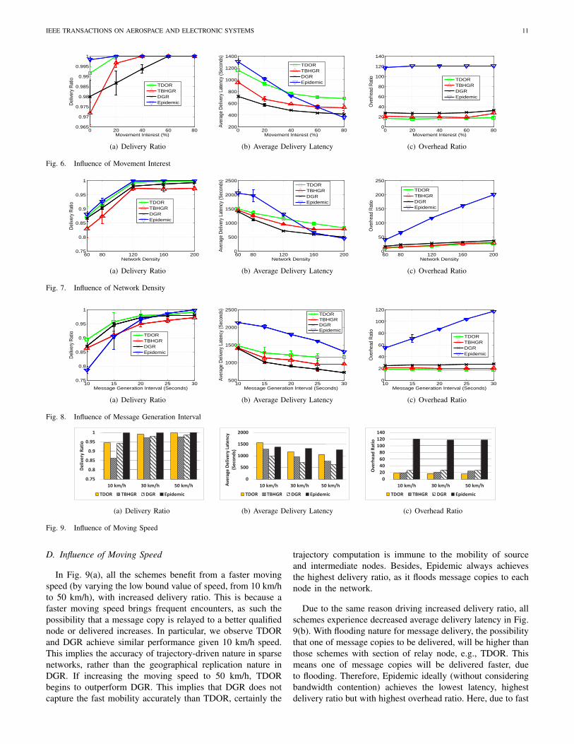
A. Influence of Movement Interest
By default, we set 0% movement interest for evaluation inother subsections, only vary it in this subsection with othersettings fixed. In Fig. 6(a), all schemes benefit from a highmovement interest, meaning the mobility of mobile nodestends to converge around those POIs. This is because nodes arehighly possible to move around dedicated POIs of areas, ratherthan just roaming across an entire network. As such, messagesare likely delivered since 3 destinations are deployed close tothose POIs. We also observe that TBHGR achieves the worstperformance, given 0% movement interest. This is becauseit limits the number of copies a message can be replicated,whereas most of them are not delivered due to infrequentencounters or not converged mobility. In comparison to DGR,the advantage of trajectory driven routing nature in TDOR isreflected through a higher delivery ratio.
In Fig. 6(b), all schemes experience a decreased averagedelivery latency, primarily due to that mobile nodes wouldmove towards destinations with high possibility. In case of80% movement interest, TDOR suffers from a higher deliverylatency than TBHGR and DGR, due to delivering moremessages shown in Fig. 6(a) from the 0% movement interestcase. Note that as these three schemes rely on relay nodeselection, their delivery latency decrease follow the sametrend. Besides, we observe Epidemic benefits from increasedmovement interest, by achieving the lowest delivery latency.This is because with flooding nature for message delivery, thepossibility that one of message copies to be delivered, willbe higher than those schemes with selection of relay node,
e.g., TDOR. As such, one of message copies will be deliveredfaster, due to flooding nature.
The observation in Fig. 6(c) shows Epidemic suffers fromthe highest overhead ratio (around 120 as the upper bound,which equals to the total number of nodes in network),due to its flooding nature. Also, the overhead ratio of DGRand TBHGR is increased, following the increased movementinterest. In contrast, TDOR achieves the lowest overhead ratiowhile keeping a stable trend, from which the efficiency oftrajectory driven routing policy is demonstrated.
B. Influence of Network DensityIn this case, the value of L in TBHGR also increases with
network density. Fig. 7(a) shows TDOR achieves a higherdelivery ratio than DGR and TBHGR. Compared to DGRwhich does not limit the number of copies a message canbe replicated, TBHGR with this limitation thereby is with theworse performance.
In Fig. 7(b), Epidemic benefits most from the increasednetwork density, with its average delivery latency decreasedwith a dramatic trend. As all message replications are limitedwith a predefined constant, TBHGR experiences the leastdecrease regarding average delivery latency. Here, since thelatency only counts for delivered messages, we consider T-DOR outperforms DGR because of a higher delivery ratio.
The observation in Fig. 7(c) shows Epidemic suffers fromthe highest overhead ratio, as it naively floods messagesto any encountered node. In comparison, TDOR, DGR andTBHGR achieve a considerable lower overhead ratio, thanksto mobility-based relay node selection. Here, the close perfor-mance between TDOR and TBHGR implies that, the trajectorydriven routing policy could reduce massive redundant messagereplications. This happens even if TDOR does not initiallylimit the number of L copies a message can be replicated (asperformed by TBHGR).
C. Influence of Message Generation IntervalIn Fig. 8(a), TDOR, DGR and TBHGR benefit from the
alleviated bandwidth contention (from 10s to 30s per messagegeneration), by achieving the increased delivery ratio. This isdifferent from Epidemic in which the bandwidth contentionbecomes dramatically in case of 10 seconds generation in-terval. Such observation implies replicating massive messagecopies does not positively contribute to delivery, particularlygiven limited communication capacity between mobile nodes.
In Fig. 8(b), as TDOR already efficiently replicates mes-sages driven by the trajectory computation at source, it doesnot benefit from alleviated bandwidth contention, thus iswithout dramatically reduced average delivery latency. In com-parison, Epidemic and DGR experience considerable benefit.This is because those infrequently generated messages willnot bring contention, as such the average delivery latencydecreases.
TDOR achieves the lowest overhead ratio in Fig. 8(c). Notethat, Epidemic and DGR are with increased overhead ratiodue to delivering more messages. This is different from theefficiency of TDOR (thanks to trajectory-driven delivery) andTBHGR (thanks to limiting L message copies).
IEEE TRANSACTIONS ON AEROSPACE AND ELECTRONIC SYSTEMS 11
0 20 40 60 800.965
0.97
0.975
0.98
0.985
0.99
0.995
1
Movement Interest (%)
Del
iver
y R
atio
TDORTBHGRDGREpidemic
(a) Delivery Ratio
0 20 40 60 80200
400
600
800
1000
1200
1400
Movement Interest (%)
Aver
age
Del
iver
y La
tenc
y (S
econ
ds)
TDORTBHGRDGREpidemic
(b) Average Delivery Latency
0 20 40 60 800
20
40
60
80
100
120
140
Movement Interest (%)
Ove
rhea
d R
atio
TDORTBHGRDGREpidemic
(c) Overhead Ratio
Fig. 6. Influence of Movement Interest
60 80 120 160 2000.75
0.8
0.85
0.9
0.95
1
Network Density
Del
iver
y R
atio
TDORTBHGRDGREpidemic
(a) Delivery Ratio
60 80 120 160 2000
500
1000
1500
2000
2500
Network Density
Aver
age
Del
iver
y La
tenc
y (S
econ
ds)
TDORTBHGRDGREpidemic
(b) Average Delivery Latency
60 80 120 160 2000
50
100
150
200
250
Network Density
Ove
rhea
d R
atio
TDORTBHGRDGREpidemic
(c) Overhead Ratio
Fig. 7. Influence of Network Density
10 15 20 25 300.75
0.8
0.85
0.9
0.95
1
Message Generation Interval (Seconds)
Del
iver
y R
atio
TDORTBHGRDGREpidemic
(a) Delivery Ratio
10 15 20 25 30500
1000
1500
2000
2500
Message Generation Interval (Seconds)
Aver
age
Del
iver
y La
tenc
y (S
econ
ds)
TDORTBHGRDGREpidemic
(b) Average Delivery Latency
10 15 20 25 300
20
40
60
80
100
120
Message Generation Interval (Seconds)
Ove
rhea
d R
atio
TDORTBHGRDGREpidemic
(c) Overhead Ratio
Fig. 8. Influence of Message Generation Interval
0.75
0.8
0.85
0.9
0.95
1
10 km/h 30 km/h 50 km/h
De
live
ry R
ati
o
TDOR TBHGR DGR Epidemic
(a) Delivery Ratio
0
500
1000
1500
2000
10 km/h 30 km/h 50 km/hAve
rage
De
live
ry L
ate
ncy
(Se
con
ds)
TDOR TBHGR DGR Epidemic
(b) Average Delivery Latency
0
20
40
60
80
100
120
140
10 km/h 30 km/h 50 km/h
Ove
rhe
ad
Ra
tio
TDOR TBHGR DGR Epidemic
(c) Overhead Ratio
Fig. 9. Influence of Moving Speed
D. Influence of Moving Speed
In Fig. 9(a), all the schemes benefit from a faster movingspeed (by varying the low bound value of speed, from 10 km/hto 50 km/h), with increased delivery ratio. This is because afaster moving speed brings frequent encounters, as such thepossibility that a message copy is relayed to a better qualifiednode or delivered increases. In particular, we observe TDORand DGR achieve similar performance given 10 km/h speed.This implies the accuracy of trajectory-driven nature in sparsenetworks, rather than the geographical replication nature inDGR. If increasing the moving speed to 50 km/h, TDORbegins to outperform DGR. This implies that DGR does notcapture the fast mobility accurately than TDOR, certainly the
trajectory computation is immune to the mobility of sourceand intermediate nodes. Besides, Epidemic always achievesthe highest delivery ratio, as it floods message copies to eachnode in the network.
Due to the same reason driving increased delivery ratio, allschemes experience decreased average delivery latency in Fig.9(b). With flooding nature for message delivery, the possibilitythat one of message copies to be delivered, will be higher thanthose schemes with section of relay node, e.g., TDOR. Thismeans one of message copies will be delivered faster, dueto flooding. Therefore, Epidemic ideally (without consideringbandwidth contention) achieves the lowest latency, highestdelivery ratio but with highest overhead ratio. Here, due to fast
IEEE TRANSACTIONS ON AEROSPACE AND ELECTRONIC SYSTEMS 12
nodal moving speed, some messages may not be successfullytransmitted, thus the delivery latency is increased.
In Fig. 9(c), TDOR achieves a decreased overhead ratio.This is mainly because that the node which is geographicallycloser (with faster speed) to the trajectory will be selectedas relay, different from TBHGR and DGR which select relaynodes that are just in proximity to destination. As such, thelatter two schemes experience an increased overhead, even incase of a faster nodal speed.
E. Influence of Distribution of Destinations
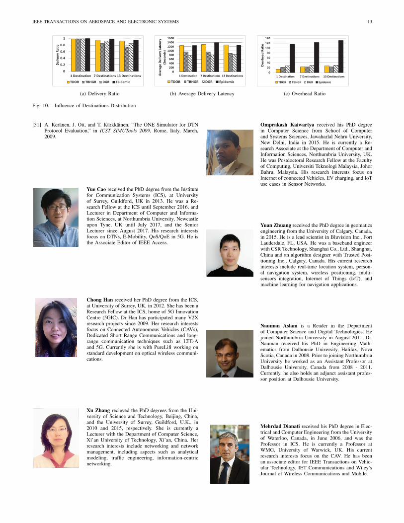
Since previous results are shown given pre-deployed desti-nations, we further implement a location distribution functiondepending on the nodal movement interest. Here, a certainnumber of coordinates of destinations are selected from the40 POIs as already illustrated in Fig. 5. For example, the casewith “7 Destinations” indicates the locations of 7 destinationsare randomly selected from 40 POIs.
In Fig. 10(a), Fig. 10(b) and Fig. 10(c), we observe that theperformance of delivering messages to a single destination,significantly differs from the case with multiple destinations.Even though an increased number of destinations will trig-ger much different trajectories towards destinations, TDORstill captures the nodal mobility associated to trajectory, byachieving a higher delivery ratio than DGR and TBHGR butwith a lower overhead ratio. This demonstrates the efficiencyof TDOR and its tolerance for the distribution of destinations.
VI. CONCLUSION
In this paper, we propose a trajectory-driven routing pro-tocol for VCPS. As the trajectory towards destination iscomputed by the source node when needed, such a sourcebased routing nature is immune to the mobility of intermediatenodes. By considering the mobility proximity to the certaintrajectory, TDOR is decoupled into a routing policy withthree cases to relay messages with differentiated transmissionorders. Evaluation results under the Helsinki city scenarioshow the advantages of TDOR over well known opportunisticgeographic routing protocols, in terms of much lower routingoverhead with comparable delivery ratio.
REFERENCES
[1] R. R. Rajkumar, I. Lee, L. Sha, and J. Stankovic, “Cyber-physicalSystems: The Next Computing Revolution,” in ACM DAC ’10, Anaheim,California, June, 2010.
[2] D. Jia, K. Lu, J. Wang, X. Zhang, and X. Shen, “A Survey on Platoon-Based Vehicular Cyber-Physical Systems,” IEEE Communications Sur-veys Tutorials, vol. 18, no. 1, pp. 263–284, First Quarter 2016.
[3] C. Suthaputchakun and Z. Sun, “Multi-hop broadcast protocol inintermittently connected vehicular networks,” IEEE Transactions onAerospace and Electronic Systems, accepted in 2016.
[4] B. Zhou, Q. Chen, H. Wymeersch, P. Xiao, and L. Zhao, “Variationalinference-based positioning with nondeterministic measurement accu-racies and reference location errors,” IEEE Transactions on MobileComputing, vol. 16, no. 10, pp. 2955–2969, October 2017.
[5] B. Zhou, Q. Chen, P. Xiao, and L. Zhao, “On the spatial error propa-gation characteristics of cooperative localization in wireless networks,”IEEE Transactions on Vehicular Technology, vol. 66, no. 2, pp. 1647–1658, February 2017.
[6] Y. Cao and Z. Sun, “Routing in Delay/Disruption Tolerant Networks:A Taxonomy, Survey and Challenges,” IEEE Communications SurveysTutorials, vol. 15, no. 2, pp. 654–677, Second Quarter, 2013.
[7] D. Zeng, S. Guo, A. Barnawi, S. Yu, and I. Stojmenovic, “An improvedstochastic modeling of opportunistic routing in vehicular cps,” IEEETransactions on Computers, vol. 64, no. 7, pp. 1819–1829, July 2015.
[8] A. Lindgren, A. Doria, and O. Schelen, “Probabilistic Routing inIntermittently Connected Networks,” ACM SIGMOBILE Mob. Comput.Commun. Rev., vol. 7, pp. 19–20, July, 2003.
[9] M. Demmer and K. Fall, “DTLSR: Delay Tolerant Routing for Devel-oping Regions,” in ACM NSDR ’07, Kyoto, Japan, August, 2007.
[10] A. Balasubramanian, B. Levine, and A. Venkataramani, “ReplicationRouting in DTNs: A Resource Allocation Approach,” IEEE/ACM Trans-actions on Networking, vol. 18, no. 2, pp. 596–609, April, 2010.
[11] K. Wei, M. Dong, K. Ota, and K. Xu, “CAMF: Context-Aware MessageForwarding in Mobile Social Networks,” IEEE Transactions on Paralleland Distributed Systems, vol. 26, no. 8, pp. 2178–2187, August 2015.
[12] Y. Cao, N. Wang, Z. Sun, and H. Cruickshank, “A Reliable and EfficientEncounter-Based Routing Framework for Delay/Disruption TolerantNetworks,” IEEE Sensors Journal, vol. 15, no. 799, pp. 4004–4018,July, 2015.
[13] J. LeBrun, C.-N. Chuah, D. Ghosal, and M. Zhang, “Knowledge-BasedOpportunistic Forwarding in Vehicular Wireless Ad Hoc Networks,” inIEEE VTC 2005-Spring, Stockholm, Sweden, May, 2005.
[14] Y. Cao, Z. Sun, N. Wang, M. Riaz, H. Cruickshank, and X. Li-u, “Geographic-Based Spray-and-Relay (GSaR): An Efficient RoutingScheme for DTNs,” IEEE Transactions on Vehicular Technology, vol. 64,no. 4, pp. 1548–1564, April, 2015.
[15] Y. Cao, Z. Sun, N. Wang, H. Cruickshank, and N. Ahmad, “A Reliableand Efficient Geographic Routing Scheme for Delay/Disruption TolerantNetworks,” IEEE Wireless Communications Letters, vol. 2, no. 6, pp.603–606, December, 2013.
[16] V. Soares, J. Rodrigues, and F. Farahmand, “GeoSpray: A GeographicRouting Protocol for Vehicular Delay-Tolerant Networks,” ElsevierInformation Fusion, vol. 15, no. 0, pp. 102–113, January, 2014.
[17] Y. Cao, K. Wei, G. Min, J. Weng, X. Yang, and Z. Sun, “A GeographicMulticopy Routing Scheme for DTNs With Heterogeneous Mobility,”IEEE Systems Journal, vol. PP, no. 99, pp. 1–12, 2016.
[18] H. Oh, S. Kim, and A. Tsourdos, “Road-map assisted standoff trackingof moving ground vehicle using nonlinear model predictive control,”IEEE Transactions on Aerospace and Electronic Systems, vol. 51, no. 2,pp. 975–986, April 2015.
[19] W. Holzapfel, M. Sofsky, and U. Neuschaefer-Rube, “Road profilerecognition for autonomous car navigation and navstar gps support,”IEEE Transactions on Aerospace and Electronic Systems, vol. 39, no. 1,pp. 2–12, January 2003.
[20] B. Karp and H. T. Kung, “GPSR: Greedy Perimeter Stateless Routingfor Wireless Networks,” in ACM MobiCom 2000, Boston, Massachusetts,USA, August, 2000.
[21] L. Liu, Z. Wang, and W. K. Jehng, “A geographic source routingprotocol for traffic sensing in urban environment,” in IEEE CASE 2008,August 2008.
[22] B.-C. Seet, G. Liu, B.-S. Lee, C.-H. Foh, K.-J. Wong, and K.-K. Lee,“A-star: A mobile ad hoc routing strategy for metropolis vehicular com-munications,” in International Conference on Information Networking2004, Athens, Greece, May 2004.
[23] D. Niculescu and B. Nath, “Trajectory Based Forwarding and ItsApplications,” in ACM MobiCom ’03, San Diego, CA, USA, 2003.
[24] T. Wang, Y. Cao, Y. Zhou, and P. Li, “A Survey on Geographic RoutingProtocols in Delay/Disruption Tolerant Networks,” International Journalof Distributed Sensor Networks, pp. 1–12, February, 2016.
[25] M. Grossglauser and D. Tse, “Mobility Increases the Capacity of Ad HocWireless Networks,” IEEE/ACM Transactions on Networking, vol. 10,no. 4, pp. 477–486, August, 2002.
[26] K. Peters, A. Jabbar, E. Cetinkaya, and J. Sterbenz, “A GeographicalRouting Protocol for Highly-Dynamic Aeronautical Networks,” in IEEEWCNC 2011, Quintana Roo, Mescio, March, 2011.
[27] A. Vahdat and D. Becker, “Epidemic Routing for Partially-Connected AdHoc Networks,” Duke University Technical Report Cs-2000-06, Tech.Rep., 2000.
[28] V. Erramilli, M. Crovella, A. Chaintreau, and C. Diot, “DelegationForwarding,” in ACM MobiHoc 2008, Hong Kong, China, May, 2008.
[29] T. Spyropoulos, K. Psounis, and C. Raghavendra, “Efficient Routing inIntermittently Connected Mobile Networks: The Multiple-Copy Case,”IEEE/ACM Transactions on Networking, vol. 16, no. 1, pp. 77 –90,February, 2008.
[30] T. Spyropoulos, T. Turletti, and K. Obraczka, “Routing in Delay-Tolerant Networks Comprising Heterogeneous Node Populations,” IEEETransactions on Mobile Computing, vol. 8, no. 8, pp. 1132–1147,August, 2009.
IEEE TRANSACTIONS ON AEROSPACE AND ELECTRONIC SYSTEMS 13
0
0.2
0.4
0.6
0.8
1
1 Destination 7 Destinations 13 Destinations
De
liv
ery
Ra
tio
TDOR TBHGR DGR Epidemic
(a) Delivery Ratio
0
200
400
600
800
1000
1200
1400
1600
1 Destination 7 Destinations 13 DestinationsAv
era
ge
De
liv
ery
La
ten
cy
(Se
con
ds)
TDOR TBHGR DGR Epidemic
(b) Average Delivery Latency
0
20
40
60
80
100
120
140
1 Destination 7 Destinations 13 Destinations
Ov
erh
ea
d R
ati
o
TDOR TBHGR DGR Epidemic
(c) Overhead Ratio
Fig. 10. Influence of Destinations Distribution
[31] A. Keranen, J. Ott, and T. Karkkainen, “The ONE Simulator for DTNProtocol Evaluation,” in ICST SIMUTools 2009, Rome, Italy, March,2009.
Yue Cao received the PhD degree from the Institutefor Communication Systems (ICS), at Universityof Surrey, Guildford, UK in 2013. He was a Re-search Fellow at the ICS until September 2016, andLecturer in Department of Computer and Informa-tion Sciences, at Northumbria University, Newcastleupon Tyne, UK until July 2017, and the SeniorLecturer since August 2017. His research interestsfocus on DTNs, E-Mobility, QoS/QoE in 5G. He isthe Associate Editor of IEEE Access.
Chong Han received her PhD degree from the ICS,at University of Surrey, UK, in 2012. She has been aResearch Fellow at the ICS, home of 5G InnovationCentre (5GIC). Dr Han has participated many V2Xresearch projects since 2009. Her research interestsfocus on Connected Autonomous Vehicles (CAVs),Dedicated Short Range Communications and long-range communication techniques such as LTE-Aand 5G. Currently she is with PureLifi working onstandard development on optical wireless communi-cations.
Xu Zhang recieved the PhD degrees from the Uni-versity of Science and Technology, Beijing, China,and the University of Surrey, Guildford, U.K., in2010 and 2015, respectively. She is currently aLecturer with the Department of Computer Science,Xi’an University of Technology, Xi’an, China. Herresearch interests include networking and networkmanagement, including aspects such as analyticalmodeling, traffic engineering, information-centricnetworking.
Omprakash Kaiwartya received his PhD degreein Computer Science from School of Computerand Systems Sciences, Jawaharlal Nehru University,New Delhi, India in 2015. He is currently a Re-search Associate at the Department of Computer andInformation Sciences, Northumbria University, UK.He was Postdoctoral Research Fellow at the Facultyof Computing, Universiti Teknologi Malaysia, JohorBahru, Malaysia. His research interests focus onInternet of connected Vehicles, EV charging, and IoTuse cases in Sensor Networks.
Yuan Zhuang received the PhD degree in geomaticsengineering from the University of Calgary, Canada,in 2015. He is a lead scientist in Bluvision Inc., FortLauderdale, FL, USA. He was a baseband engineerwith CSR Technology, Shanghai Co., Ltd., Shanghai,China and an algorithm designer with Trusted Posi-tioning Inc., Calgary, Canada. His current researchinterests include real-time location system, person-al navigation system, wireless positioning, multi-sensors integration, Internet of Things (IoT), andmachine learning for navigation applications.
Nauman Aslam is a Reader in the Departmentof Computer Science and Digital Technologies. Hejoined Northumbria University in August 2011. Dr.Nauman received his PhD in Engineering Math-ematics from Dalhousie University, Halifax, NovaScotia, Canada in 2008. Prior to joining NorthumbriaUniversity he worked as an Assistant Professor atDalhousie University, Canada from 2008 - 2011.Currently, he also holds an adjunct assistant profes-sor position at Dalhousie University.
Mehrdad Dianati received his PhD degree in Elec-trical and Computer Engineering from the Universityof Waterloo, Canada, in June 2006, and was theProfessor in ICS. He is currently a Professor atWMG, University of Warwick, UK. His currentresearch interests focus on the CAV. He has beenan associate editor for IEEE Transactions on Vehic-ular Technology, IET Communications and Wiley’sJournal of Wireless Communications and Mobile.