IEEE SYSTEMS JOURNAL, VOL. 6, NO. 2, JUNE 2012 329 High-Capacity OFDMA Femtocells ... ·...
12
IEEE SYSTEMS JOURNAL, VOL. 6, NO. 2, JUNE 2012 329 High-Capacity OFDMA Femtocells by Directional Antennas and Location Awareness Ang-Hsun Tsai, Student Member, IEEE, Li-Chun Wang, Fellow, IEEE, Jane-Hwa Huang, Member, IEEE, and Ruey-Bing Hwang, Senior Member, IEEE Abstract —In this paper, we propose a location-aware mecha- nism combined with a low-cost four-sector switched-beam direc- tional antenna to enhance the spectrum efficiency of orthogonal frequency-division multiple access (OFDMA)-based femtocell systems. The considered location-awareness capability is specified in the current IEEE 802.16m WiMAX standard, but has not been applied to avoid the interference between indoor femtocells and outdoor macrocells. With the knowledge of the locations of outdoor users, the proposed four-sector switched-beam antenna in a femtocell can effectively avoid the interference among femtocells and macrocells by adjusting the number of OFDMA subcarriers used at each femtocell. Numerical results show that the proposed approach can significantly improve spectrum efficiency compared to the existing methods. Index Terms—Closed subscriber group (CSG), femtocell, four-sector switched-beam directional antenna, link reliability, location awareness, open subscriber group (OSG), orthogonal frequency-division multiple access (OFDMA), spectrum efficiency, two-tier interference. I. Introduction F EMTOCELLS can improve system capacity and indoor coverage with low power and low cost [1]–[4]. Un- like base stations in conventional cellular systems, femto- cells connect to the network center through the broadband wirelines inside the customers’ homes. Due to short trans- mission distance, femtocells require very low transmission power. From the operator’s viewpoint, deploying femtocells can also significantly improve system capacity because the same spectrum can be repeatedly used by a huge number of other femtocells. Femtocells can also off-load the traffic of the outdoor macrocell users toward the indoor femtocell base station (fBS). From the customers’ perspective, the fBS Manuscript received June 30, 2011; revised November 2, 2011; accepted November 7, 2011. Date of publication January 10, 2012; date of current version May 22, 2012. This work was supported in part by the National Science Council (NSC) of Taiwan, under Research Grant NSC 100-2221-E- 009-103-MY3, and in part by the Industrial Technology Research Institute, Information and Communication Research Laboratories, Taiwan. Part of this work was presented at the IEEE Wireless Communications and Networking Conference, 2010. A.-H. Tsai, L.-C. Wang, and R.-B. Hwang are with the Department of Electrical Engineering, National Chiao Tung University, Hsinchu 300, Taiwan (e-mail: [email protected]; [email protected]; raybeam@ mail.nctu.edu.tw). J.-H. Huang is with the Department of Electrical Engineering, National Chi Nan University, Nantou 545, Taiwan (e-mail: [email protected]). Color versions of one or more of the figures in this paper are available online at http://ieeexplore.ieee.org. Digital Object Identifier 10.1109/JSYST.2011.2178724 is much closer than the outdoor macrocell base station (mBS), thereby improving indoor signal quality. However, the serious two-tier interference in femtocells is the key challenge [2]–[5]. After femtocells are densely deployed, both the femto-to-femto and the macro-to-femto interference occur. In the meanwhile, the macrocell users undergo the interference from the femtocells and macrocells as well. The severe two-tier interference significantly affects the system capacity because the subcarriers available for the femtocells are reduced. In the literature, most studies on femtocells considered the omnidirectional femtocells and can be categorized into three kinds: power control, access method, and spectrum allocation. In [1] and [6], the power control method for femtocells with omnidirectional antenna were discussed. In [1], an autoconfig- uration method of transmit power was proposed for the code division multiple access (CDMA)-based femtocells with the shared spectrum allocation scheme. In [6], the authors pro- posed a distributed femtocell uplink power control to achieve higher signal-to-interference plus noise ratio performance on the condition that the link quality of the macrocell users can be guaranteed. Access methods for femtocells were discussed in [3], [7], and [8]. In [3], the authors compared the closed subscriber group (CSG) and open subscriber group (OSG) femtocell systems, where the CSG fBSs only serve the authorized users, and the OSG fBSs can serve any users. Because the OSG users can select the base station with best signal quality among the femtocells and macrocells, the OSG scheme has better coverage than the CSG scheme. In [7], the authors studied different access methods for femtocells and proposed a hybrid access approach to improve the average throughput. In [8], the authors investigated the effects of access methods in the uplink femtocell systems. They suggested that the access method depend on the cellular user density in the time division multiple access/orthogonal frequency-division multiple access (OFDMA) network, and showed that open access is the optimal choice in the CDMA network. In [9]–[14], spectrum allocation schemes for femtocells with omnidirectional antenna were discussed. In [9], the channel selection issues in the WiMAX-based femtocell systems was investigated by taking into account of the femto-to-femto inter- ference. In [11], distributed channel selection schemes for fem- tocells were developed to improve the capacity by adjusting the number of used subcarriers. In [10], the authors analyzed 1932-8184/$31.00 c 2012 IEEE
Transcript of IEEE SYSTEMS JOURNAL, VOL. 6, NO. 2, JUNE 2012 329 High-Capacity OFDMA Femtocells ... ·...
IEEE SYSTEMS JOURNAL, VOL. 6, NO. 2, JUNE 2012 329
High-Capacity OFDMA Femtocells by DirectionalAntennas and Location Awareness
Ang-Hsun Tsai, Student Member, IEEE, Li-Chun Wang, Fellow, IEEE, Jane-Hwa Huang, Member, IEEE, andRuey-Bing Hwang, Senior Member, IEEE
Abstract—In this paper, we propose a location-aware mecha-nism combined with a low-cost four-sector switched-beam direc-tional antenna to enhance the spectrum efficiency of orthogonalfrequency-division multiple access (OFDMA)-based femtocellsystems. The considered location-awareness capability is specifiedin the current IEEE 802.16m WiMAX standard, but has notbeen applied to avoid the interference between indoor femtocellsand outdoor macrocells. With the knowledge of the locations ofoutdoor users, the proposed four-sector switched-beam antennain a femtocell can effectively avoid the interference amongfemtocells and macrocells by adjusting the number of OFDMAsubcarriers used at each femtocell. Numerical results showthat the proposed approach can significantly improve spectrumefficiency compared to the existing methods.
Index Terms—Closed subscriber group (CSG), femtocell,four-sector switched-beam directional antenna, link reliability,location awareness, open subscriber group (OSG), orthogonalfrequency-division multiple access (OFDMA), spectrumefficiency, two-tier interference.
I. Introduction
FEMTOCELLS can improve system capacity and indoorcoverage with low power and low cost [1]–[4]. Un-
like base stations in conventional cellular systems, femto-cells connect to the network center through the broadbandwirelines inside the customers’ homes. Due to short trans-mission distance, femtocells require very low transmissionpower. From the operator’s viewpoint, deploying femtocellscan also significantly improve system capacity because thesame spectrum can be repeatedly used by a huge numberof other femtocells. Femtocells can also off-load the trafficof the outdoor macrocell users toward the indoor femtocellbase station (fBS). From the customers’ perspective, the fBS
Manuscript received June 30, 2011; revised November 2, 2011; acceptedNovember 7, 2011. Date of publication January 10, 2012; date of currentversion May 22, 2012. This work was supported in part by the NationalScience Council (NSC) of Taiwan, under Research Grant NSC 100-2221-E-009-103-MY3, and in part by the Industrial Technology Research Institute,Information and Communication Research Laboratories, Taiwan. Part of thiswork was presented at the IEEE Wireless Communications and NetworkingConference, 2010.
A.-H. Tsai, L.-C. Wang, and R.-B. Hwang are with the Departmentof Electrical Engineering, National Chiao Tung University, Hsinchu 300,Taiwan (e-mail: [email protected]; [email protected]; [email protected]).
J.-H. Huang is with the Department of Electrical Engineering, National ChiNan University, Nantou 545, Taiwan (e-mail: [email protected]).
Color versions of one or more of the figures in this paper are availableonline at http://ieeexplore.ieee.org.
Digital Object Identifier 10.1109/JSYST.2011.2178724
is much closer than the outdoor macrocell base station (mBS),thereby improving indoor signal quality.
However, the serious two-tier interference in femtocellsis the key challenge [2]–[5]. After femtocells are denselydeployed, both the femto-to-femto and the macro-to-femtointerference occur. In the meanwhile, the macrocell usersundergo the interference from the femtocells and macrocellsas well. The severe two-tier interference significantly affectsthe system capacity because the subcarriers available for thefemtocells are reduced.
In the literature, most studies on femtocells considered theomnidirectional femtocells and can be categorized into threekinds: power control, access method, and spectrum allocation.
In [1] and [6], the power control method for femtocells withomnidirectional antenna were discussed. In [1], an autoconfig-uration method of transmit power was proposed for the codedivision multiple access (CDMA)-based femtocells with theshared spectrum allocation scheme. In [6], the authors pro-posed a distributed femtocell uplink power control to achievehigher signal-to-interference plus noise ratio performance onthe condition that the link quality of the macrocell users canbe guaranteed.
Access methods for femtocells were discussed in [3], [7],and [8]. In [3], the authors compared the closed subscribergroup (CSG) and open subscriber group (OSG) femtocellsystems, where the CSG fBSs only serve the authorized users,and the OSG fBSs can serve any users. Because the OSGusers can select the base station with best signal qualityamong the femtocells and macrocells, the OSG scheme hasbetter coverage than the CSG scheme. In [7], the authorsstudied different access methods for femtocells and proposeda hybrid access approach to improve the average throughput.In [8], the authors investigated the effects of access methodsin the uplink femtocell systems. They suggested that theaccess method depend on the cellular user density in thetime division multiple access/orthogonal frequency-divisionmultiple access (OFDMA) network, and showed that openaccess is the optimal choice in the CDMA network.
In [9]–[14], spectrum allocation schemes for femtocells withomnidirectional antenna were discussed. In [9], the channelselection issues in the WiMAX-based femtocell systems wasinvestigated by taking into account of the femto-to-femto inter-ference. In [11], distributed channel selection schemes for fem-tocells were developed to improve the capacity by adjustingthe number of used subcarriers. In [10], the authors analyzed
1932-8184/$31.00 c© 2012 IEEE

330 IEEE SYSTEMS JOURNAL, VOL. 6, NO. 2, JUNE 2012
the optimal fraction of spectrum allocated to macrocell andfemtocell systems, in which the macrocell and femtocell sys-tems are assigned with different frequency bands. In [12], theauthors designed an on-demand two-tier resource allocationmechanism to improve the system throughput. In [13], theauthors proposed the cognitive radio resource managementscheme for femtocell networks to achieve the higher capacitywith ensuring the delay requirement. Afterward, they furtherproposed the strategic game-based radio resource managementscheme for femtocells to alleviate the severe femto-to-femtointerference as well as improve the system capacity with thedelay guarantee [14].
Fewer papers have examined the femtocell systems withdirectional antennas, such as [15]–[19]. Intuitively, directionalantennas can increase signal strength due to higher antennagain and decrease the interference due to the narrow-beam pat-terns. In [15], the uplink capacity in CDMA-based femtocellnetworks using sector antennas and time-hopping techniqueswere analyzed. The multiple antennas in CDMA-based femto-cell systems were applied to reduce the unnecessary handoverand enhance the indoor coverage [16]. However, the mainfocus of [15] and [16] was on the shared spectrum allocationscheme in the CDMA-based femtocell systems.
The receive antenna diversity was applied to mitigate the up-link co-channel interference and improve the signal receptionquality for femtocells [17], [18]. In [19], the authors proposedpower control method using switched parasitic array antennain OFDMA-based femtocell networks to avoid the co-channelinterference to macrocell users. Nevertheless, the works of[17]–[19] aimed to alleviate the co-channel interference bythe antenna diversity. They did not investigate the impacts ofthe location of outdoor users and they also did not apply thepartial usage of femtocell subcarriers approach to reduce thefemto-to-macro interference. In our previous work [20], thecapacity and link reliability of low-cost E-plane horns-basedreconfigurable directional antenna for the OFDMA-based fem-tocell systems were investigated. The major research in [20]was to investigate the impact of directional antenna on the linkreliability and capacity of indoor users. However, the impactof femtocells on outdoor users was not considered in [20].
In this paper, we develop a subcarrier number adjustmentmethod combining with location-aware capability to mitigatethe two-tier interference in OFDMA-based femtocell systems.We consider a four-sector switched-beam OFDMA-based fem-tocell system and utilize the location awareness capability inthe IEEE 802.16m WiMAX system [21]. When an outdooruser is close to a femtocell, the number of occupied subcarriersis reduced to lower the interference. If an outdoor user is faraway from the femtocells, the subcarriers can be fully utilizedby the femtocell’s users. We show that the proposed location-aware switched-beam femtocell system can improve its spec-trum efficiency due to its capability of avoid interference tothe outdoor users.
The remainder of this paper is organized as follows. Sec-tion II describes the system architecture, the proposed locationawareness scheme, and the channel models. The major perfor-mance metrics are discussed in Section III. In Section IV, wecompare radiation patterns of the four-sector switched-beam
Fig. 1. Illustrative example of the two-tier inference scenario in femtocells.(a) Cluster of 25 femtocells, each of which faces femto-to-femto and macro-to-femto interference. (b) Each four-sector femtocell is surrounded by thestreets with (dsf − 10)/2 m and one macrocell user is appeared in the streetarea of 25 femtocells.
Fig. 2. Two-tier interference for outdoor users with two access methods.(a) CSG access method. (b) OSG access method.
directional antenna and the IEEE 802.16m sector antenna.We show the simulation results in Section V. Finally, ourconcluding remarks and future works are given in Section VI.
II. System Models
A. System Architecture
We consider the OFDMA-based femtocell systems in thecampus or community environment. Fig. 1(a) shows a clusterof 25 femtocells and a macrocell with a radius of Rm m.Assume that each house covers an area of 100 m2 and hasfour 5 × 5 m2 rooms. Let the fBS be deployed at the centerof each house with a shift of (0.1 m, 0.1 m), and denote dsf mas the separation distance between two neighboring fBSs. Itis assumed that the femtocell user’s locations are uniformlydistributed within the house, and one outdoor user is located inthe shadowed region with width of (dsf −10)/2 m surroundingthe house, as shown in Fig. 1(b).
Both the exclusive and shared spectrum allocation schemesin OFDMA-based femtocells are considered in our model.The former scheme allocates different frequency bands to
TSAI et al.: HIGH-CAPACITY OFDMA FEMTOCELLS 331
the macrocell and femtocell system, and the later schemeallows the same spectrum shared by both the marcocelland femtocell system. Compared with the shared spectrumallocation schemes, the exclusive spectrum allocation schemecan reduce the mutual interference, but may have lowerspectrum efficiency. On the contrary, the shared spectrumscheme can increase the spectrum efficiency at the cost ofhigher two-tier interference.
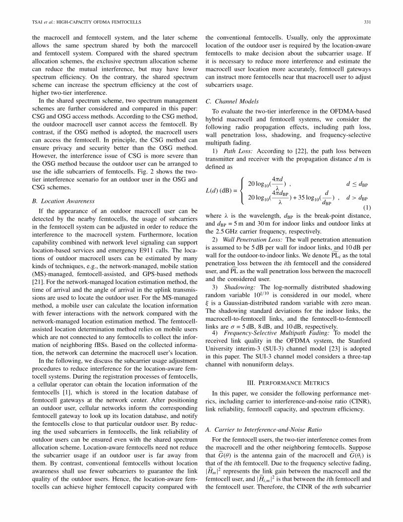
In the shared spectrum scheme, two spectrum managementschemes are further considered and compared in this paper:CSG and OSG access methods. According to the CSG method,the outdoor macrocell user cannot access the femtocell. Bycontrast, if the OSG method is adopted, the macrocell userscan access the femtocell. In principle, the CSG method canensure privacy and security better than the OSG method.However, the interference issue of CSG is more severe thanthe OSG method because the outdoor user can be arranged touse the idle subcarriers of femtocells. Fig. 2 shows the two-tier interference scenario for an outdoor user in the OSG andCSG schemes.
B. Location Awareness
If the appearance of an outdoor macrocell user can bedetected by the nearby femtocells, the usage of subcarriersin the femtocell system can be adjusted in order to reduce theinterference to the macrocell system. Furthermore, locationcapability combined with network level signaling can supportlocation-based services and emergency E911 calls. The loca-tions of outdoor macrocell users can be estimated by manykinds of techniques, e.g., the network-managed, mobile station(MS)-managed, femtocell-assisted, and GPS-based methods[21]. For the network-managed location estimation method, thetime of arrival and the angle of arrival in the uplink transmis-sions are used to locate the outdoor user. For the MS-managedmethod, a mobile user can calculate the location informationwith fewer interactions with the network compared with thenetwork-managed location estimation method. The femtocell-assisted location determination method relies on mobile userswhich are not connected to any femtocells to collect the infor-mation of neighboring fBSs. Based on the collected informa-tion, the network can determine the macrocell user’s location.
In the following, we discuss the subcarrier usage adjustmentprocedures to reduce interference for the location-aware fem-tocell systems. During the registration processes of femtocells,a cellular operator can obtain the location information of thefemtocells [1], which is stored in the location database offemtocell gateways at the network center. After positioningan outdoor user, cellular networks inform the correspondingfemtocell gateway to look up its location database, and notifythe femtocells close to that particular outdoor user. By reduc-ing the used subcarriers in femtocells, the link reliability ofoutdoor users can be ensured even with the shared spectrumallocation scheme. Location-aware femtocells need not reducethe subcarrier usage if an outdoor user is far away fromthem. By contrast, conventional femtocells without locationawareness shall use fewer subcarriers to guarantee the linkquality of the outdoor users. Hence, the location-aware fem-tocells can achieve higher femtocell capacity compared with
the conventional femtocells. Usually, only the approximatelocation of the outdoor user is required by the location-awarefemtocells to make decision about the subcarrier usage. Ifit is necessary to reduce more interference and estimate themacrocell user location more accurately, femtocell gatewayscan instruct more femtocells near that macrocell user to adjustsubcarriers usage.
C. Channel Models
To evaluate the two-tier interference in the OFDMA-basedhybrid macrocell and femtocell systems, we consider thefollowing radio propagation effects, including path loss,wall penetration loss, shadowing, and frequency-selectivemultipath fading.
1) Path Loss: According to [22], the path loss betweentransmitter and receiver with the propagation distance d m isdefined as
L(d) (dB) =
⎧⎪⎨⎪⎩
20 log10(4πd
λ) , d ≤ dBP
20 log10(4πdBP
λ) + 35 log10(
d
dBP) , d > dBP
(1)where λ is the wavelength, dBP is the break-point distance,and dBP = 5 m and 30 m for indoor links and outdoor links atthe 2.5 GHz carrier frequency, respectively.
2) Wall Penetration Loss: The wall penetration attenuationis assumed to be 5 dB per wall for indoor links, and 10 dB perwall for the outdoor-to-indoor links. We denote PLi as the totalpenetration loss between the ith femtocell and the considereduser, and PL as the wall penetration loss between the macrocelland the considered user.
3) Shadowing: The log-normally distributed shadowingrandom variable 10ξ/10 is considered in our model, whereξ is a Gaussian-distributed random variable with zero mean.The shadowing standard deviations for the indoor links, themacrocell-to-femtocell links, and the femtocell-to-femtocelllinks are σ = 5 dB, 8 dB, and 10 dB, respectively.
4) Frequency-Selective Multipath Fading: To model thereceived link quality in the OFDMA system, the StanfordUniversity interim-3 (SUI-3) channel model [23] is adoptedin this paper. The SUI-3 channel model considers a three-tapchannel with nonuniform delays.
III. Performance Metrics
In this paper, we consider the following performance met-rics, including carrier to interference-and-noise ratio (CINR),link reliability, femtocell capacity, and spectrum efficiency.
A. Carrier to Interference-and-Noise Ratio
For the femtocell users, the two-tier interference comes fromthe macrocell and the other neighboring femtocells. Supposethat G(θ) is the antenna gain of the macrocell and G(θi) isthat of the ith femtocell. Due to the frequency selective fading,|Hm|2 represents the link gain between the macrocell and thefemtocell user, and |Hi,m|2 is that between the ith femtocell andthe femtocell user. Therefore, the CINR of the mth subcarrier
332 IEEE SYSTEMS JOURNAL, VOL. 6, NO. 2, JUNE 2012
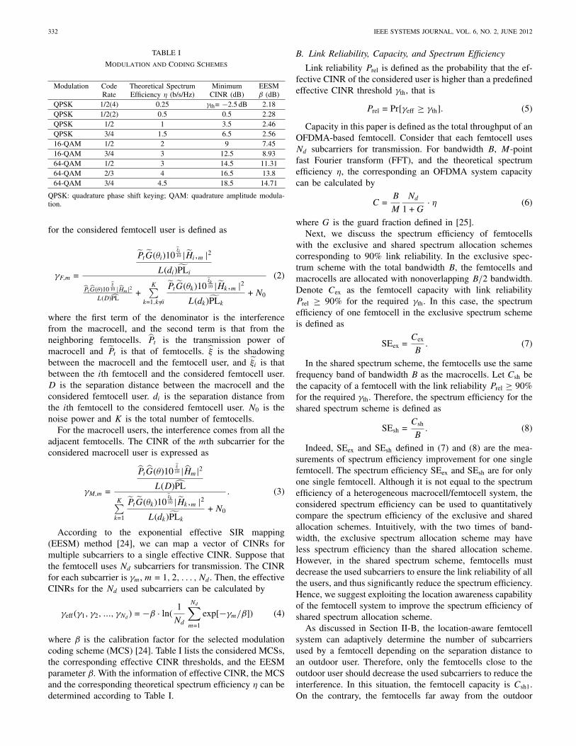
TABLE I
Modulation and Coding Schemes
Modulation Code Theoretical Spectrum Minimum EESMRate Efficiency η (b/s/Hz) CINR (dB) β (dB)
QPSK 1/2(4) 0.25 γth= −2.5 dB 2.18QPSK 1/2(2) 0.5 0.5 2.28QPSK 1/2 1 3.5 2.46QPSK 3/4 1.5 6.5 2.5616-QAM 1/2 2 9 7.4516-QAM 3/4 3 12.5 8.9364-QAM 1/2 3 14.5 11.3164-QAM 2/3 4 16.5 13.864-QAM 3/4 4.5 18.5 14.71
QPSK: quadrature phase shift keying; QAM: quadrature amplitude modula-tion.
for the considered femtocell user is defined as
γF,m =
PtG(θi)10˜ξi10 |Hi,m |2
L(di)PLi
PtG(θ)10
ξ10 |Hm|2
L(D)PL+
K∑k=1,k �=i
PtG(θk)10˜ξk10 |Hk,m |2
L(dk)PLk
+ N0
(2)
where the first term of the denominator is the interferencefrom the macrocell, and the second term is that from theneighboring femtocells. Pt is the transmission power ofmacrocell and Pt is that of femtocells. ξ is the shadowingbetween the macrocell and the femtocell user, and ξi is thatbetween the ith femtocell and the considered femtocell user.D is the separation distance between the macrocell and theconsidered femtocell user. di is the separation distance fromthe ith femtocell to the considered femtocell user. N0 is thenoise power and K is the total number of femtocells.
For the macrocell users, the interference comes from all theadjacent femtocells. The CINR of the mth subcarrier for theconsidered macrocell user is expressed as
γM,m =
PtG(θ)10ξ
10 |Hm|2L(D)PL
K∑k=1
PtG(θk)10˜ξk10 |Hk,m |2
L(dk)PLk
+ N0
. (3)
According to the exponential effective SIR mapping(EESM) method [24], we can map a vector of CINRs formultiple subcarriers to a single effective CINR. Suppose thatthe femtocell uses Nd subcarriers for transmission. The CINRfor each subcarrier is γm, m = 1, 2, . . . , Nd . Then, the effectiveCINRs for the Nd used subcarriers can be calculated by
γeff (γ1, γ2, ..., γNd) = −β · ln(
1
Nd
Nd∑m=1
exp[−γm/β]) (4)
where β is the calibration factor for the selected modulationcoding scheme (MCS) [24]. Table I lists the considered MCSs,the corresponding effective CINR thresholds, and the EESMparameter β. With the information of effective CINR, the MCSand the corresponding theoretical spectrum efficiency η can bedetermined according to Table I.
B. Link Reliability, Capacity, and Spectrum Efficiency
Link reliability Prel is defined as the probability that the ef-fective CINR of the considered user is higher than a predefinedeffective CINR threshold γth, that is
Prel = Pr[γeff ≥ γth]. (5)
Capacity in this paper is defined as the total throughput of anOFDMA-based femtocell. Consider that each femtocell usesNd subcarriers for transmission. For bandwidth B, M-pointfast Fourier transform (FFT), and the theoretical spectrumefficiency η, the corresponding an OFDMA system capacitycan be calculated by
C =B
M
Nd
1 + G· η (6)
where G is the guard fraction defined in [25].Next, we discuss the spectrum efficiency of femtocells
with the exclusive and shared spectrum allocation schemescorresponding to 90% link reliability. In the exclusive spec-trum scheme with the total bandwidth B, the femtocells andmacrocells are allocated with nonoverlapping B/2 bandwidth.Denote Cex as the femtocell capacity with link reliabilityPrel ≥ 90% for the required γth. In this case, the spectrumefficiency of one femtocell in the exclusive spectrum schemeis defined as
SEex =Cex
B. (7)
In the shared spectrum scheme, the femtocells use the samefrequency band of bandwidth B as the macrocells. Let Csh bethe capacity of a femtocell with the link reliability Prel ≥ 90%for the required γth. Therefore, the spectrum efficiency for theshared spectrum scheme is defined as
SEsh =Csh
B. (8)
Indeed, SEex and SEsh defined in (7) and (8) are the mea-surements of spectrum efficiency improvement for one singlefemtocell. The spectrum efficiency SEex and SEsh are for onlyone single femtocell. Although it is not equal to the spectrumefficiency of a heterogeneous macrocell/femtocell system, theconsidered spectrum efficiency can be used to quantitativelycompare the spectrum efficiency of the exclusive and sharedallocation schemes. Intuitively, with the two times of band-width, the exclusive spectrum allocation scheme may haveless spectrum efficiency than the shared allocation scheme.However, in the shared spectrum scheme, femtocells mustdecrease the used subcarriers to ensure the link reliability of allthe users, and thus significantly reduce the spectrum efficiency.Hence, we suggest exploiting the location awareness capabilityof the femtocell system to improve the spectrum efficiency ofshared spectrum allocation scheme.
As discussed in Section II-B, the location-aware femtocellsystem can adaptively determine the number of subcarriersused by a femtocell depending on the separation distance toan outdoor user. Therefore, only the femtocells close to theoutdoor user should decrease the used subcarriers to reduce theinterference. In this situation, the femtocell capacity is Csh1.On the contrary, the femtocells far away from the outdoor

TSAI et al.: HIGH-CAPACITY OFDMA FEMTOCELLS 333
user can still use all subcarriers with capacity Csh0. Supposethat the probability that there is an outdoor user around theconsidered femtocell is p. With the location awareness, theaverage spectrum efficiency for the shared spectrum allocationscheme can increase to
SELA =pCsh1 + (1 − p)Csh0
B. (9)
The existence probability p of an outdoor user around afemtocell can be measured by the femtocell [16] from the long-term statistics depending on the population density, femtocelldensity, femtocell transmission power, and so on.
To achieve higher spectrum efficiency, the location-awarefemtocell system need to adaptively operate in the suitablespectrum allocation scheme and access method according tothe existence probability p of an outdoor user and the proba-bility threshold p∗. The probability threshold p∗ for selectingthe spectrum sharing scheme can be obtained as follows, sinceSELA is the average spectrum efficiency for a location-awarefemtocell system, as defined in (9). In the condition that usingthe shared spectrum scheme in the location-aware femtocellsystem can have higher spectrum efficiency than using theexclusive spectrum scheme, we have
SELA =pCsh1 + (1 − p)Csh0
B≥ SEex =
Cex
B. (10)
Then, by rearranging (10), we can find the probability thresh-old p∗ as
p ≤ p∗ =Csh0 − 1
2Cex
Csh0 − Csh1. (11)
Accordingly, for the location-aware femtocell system, theshared spectrum allocation scheme can achieve higher spec-trum efficiency than the exclusive spectrum allocation schemeas p < p∗. The location-aware femtocell need to periodicallyreport the existence probability of outdoor users to the fem-tocell gateway at the network center. Then, femtocell gatewaycan calculate the probability threshold by (11) in advance, andadaptively instruct the location-aware femtocells to switch thesuitable spectrum allocation and access method. For a givenenvironment, the location-aware femtocells can operate in theshared spectrum allocation scheme if p < p∗. Otherwise,the location-aware femtocells should work in the exclusivespectrum allocation scheme to achieve the best spectrumefficiency.
IV. Directional Antennas for Femtocells
Directional antennas can decrease the two-tier interferenceand thus improve femtocell capacity. For now, most of thefBSs are equipped with only omnidirectional antennas, whichhave lower antenna gain. In addition, each user will beeasily interfered by neighboring femtocells. On the contrary,directional antennas can reduce the interference to adjacentfemtocells and achieve the better CINR due to high main lobegain and narrow beam pattern. In this section, we comparethe four-sector switched-beam antenna and the IEEE 802.16msector antenna.
Fig. 3. (a) Structure of four-sector switched-beam directional antenna.(b) Structure of the prototype. (c) Circuitry for the four-sector switched-beamdirectional antenna with the transistor-based switch.
Fig. 4. Each beam pattern of four-sector switched-beam directional antenna.
A. IEEE 802.16m Sector Antenna
We consider the sector antenna in the IEEE 802.16m system[26] which has the radiation pattern A(θ) as follows:
A(θ) = − min[12
(θ
θ3 dB
)2
, Am] (dB) (12)
where θ3 dB is the 3 dB beamwidth (corresponding to θ = 70°),and Am = 20 dB is the maximum attenuation. The sectorantenna pattern in the IEEE 802.16m is mainly designed foroutdoor environments. We consider a four-sector fBS thatfollows the above antenna pattern. Such a four-sector femtocellrequires four radio transceivers, yielding higher implementa-tion cost.
B. Four-Sector Switched-Beam Directional Antenna
To resolve the high implementation cost issue of the four-sector femtocell using the IEEE 802.16m sector antenna,
334 IEEE SYSTEMS JOURNAL, VOL. 6, NO. 2, JUNE 2012
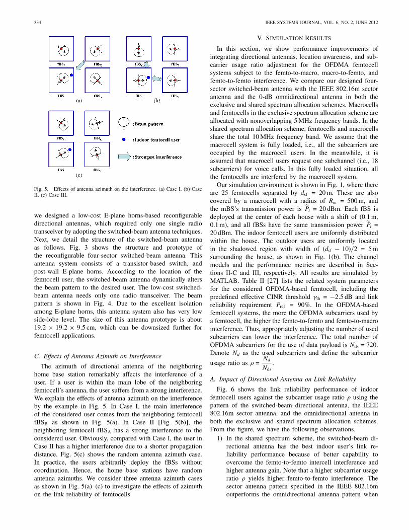
Fig. 5. Effects of antenna azimuth on the interference. (a) Case I. (b) CaseII. (c) Case III.
we designed a low-cost E-plane horns-based reconfigurabledirectional antennas, which required only one single radiotransceiver by adopting the switched-beam antenna techniques.Next, we detail the structure of the switched-beam antennaas follows. Fig. 3 shows the structure and prototype ofthe reconfigurable four-sector switched-beam antenna. Thisantenna system consists of a transistor-based switch, andpost-wall E-plane horns. According to the location of thefemtocell user, the switched-beam antenna dynamically altersthe beam pattern to the desired user. The low-cost switched-beam antenna needs only one radio transceiver. The beampattern is shown in Fig. 4. Due to the excellent isolationamong E-plane horns, this antenna system also has very lowside-lobe level. The size of this antenna prototype is about19.2 × 19.2 × 9.5 cm, which can be downsized further forfemtocell applications.
C. Effects of Antenna Azimuth on Interference
The azimuth of directional antenna of the neighboringhome base station remarkably affects the interference of auser. If a user is within the main lobe of the neighboringfemtocell’s antenna, the user suffers from a strong interference.We explain the effects of antenna azimuth on the interferenceby the example in Fig. 5. In Case I, the main interferenceof the considered user comes from the neighboring femtocellfBSB as shown in Fig. 5(a). In Case II [Fig. 5(b)], theneighboring femtocell fBSA has a strong interference to theconsidered user. Obviously, compared with Case I, the user inCase II has a higher interference due to a shorter propagationdistance. Fig. 5(c) shows the random antenna azimuth case.In practice, the users arbitrarily deploy the fBSs withoutcoordination. Hence, the home base stations have randomantenna azimuths. We consider three antenna azimuth casesas shown in Fig. 5(a)–(c) to investigate the effects of azimuthon the link reliability of femtocells.
V. Simulation Results
In this section, we show performance improvements ofintegrating directional antennas, location awareness, and sub-carrier usage ratio adjustment for the OFDMA femtocellsystems subject to the femto-to-macro, macro-to-femto, andfemto-to-femto interference. We compare our designed four-sector switched-beam antenna with the IEEE 802.16m sectorantenna and the 0-dB omnidirectional antenna in both theexclusive and shared spectrum allocation schemes. Macrocellsand femtocells in the exclusive spectrum allocation scheme areallocated with nonoverlapping 5 MHz frequency bands. In theshared spectrum allocation scheme, femtocells and macrocellsshare the total 10 MHz frequency band. We assume that themacrocell system is fully loaded, i.e., all the subcarriers areoccupied by the macrocell users. In the meanwhile, it isassumed that macrocell users request one subchannel (i.e., 18subcarriers) for voice calls. In this fully loaded situation, allthe femtocells are interfered by the macrocell system.
Our simulation environment is shown in Fig. 1, where thereare 25 femtocells separated by dsf = 20 m. These are alsocovered by a macrocell with a radius of Rm = 500 m, andthe mBS’s transmission power is Pt = 20 dBm. Each fBS isdeployed at the center of each house with a shift of (0.1 m,0.1 m), and all fBSs have the same transmission power Pt =20 dBm. The indoor femtocell users are uniformly distributedwithin the house. The outdoor users are uniformly locatedin the shadowed region with width of (dsf − 10)/2 = 5 msurrounding the house, as shown in Fig. 1(b). The channelmodels and the performance metrics are described in Sec-tions II-C and III, respectively. All results are simulated byMATLAB. Table II [27] lists the related system parametersfor the considered OFDMA-based femtocell, including thepredefined effective CINR threshold γth = −2.5 dB and linkreliability requirement Prel = 90%. In the OFDMA-basedfemtocell systems, the more the OFDMA subcarriers used bya femtocell, the higher the femto-to-femto and femto-to-macrointerference. Thus, appropriately adjusting the number of usedsubcarriers can lower the interference. The total number ofOFDMA subcarriers for the use of data payload is Nds = 720.Denote Nd as the used subcarriers and define the subcarrier
usage ratio as ρ =Nd
Nds.
A. Impact of Directional Antenna on Link Reliability
Fig. 6 shows the link reliability performance of indoorfemtocell users against the subcarrier usage ratio ρ using thepattern of the switched-beam directional antenna, the IEEE802.16m sector antenna, and the omnidirectional antenna inboth the exclusive and shared spectrum allocation schemes.From the figure, we have the following observations.
1) In the shared spectrum scheme, the switched-beam di-rectional antenna has the best indoor user’s link re-liability performance because of better capability toovercome the femto-to-femto intercell interference andhigher antenna gain. Note that a higher subcarrier usageratio ρ yields higher femto-to-femto interference. Thesector antenna pattern specified in the IEEE 802.16moutperforms the omnidirectional antenna pattern when
TSAI et al.: HIGH-CAPACITY OFDMA FEMTOCELLS 335
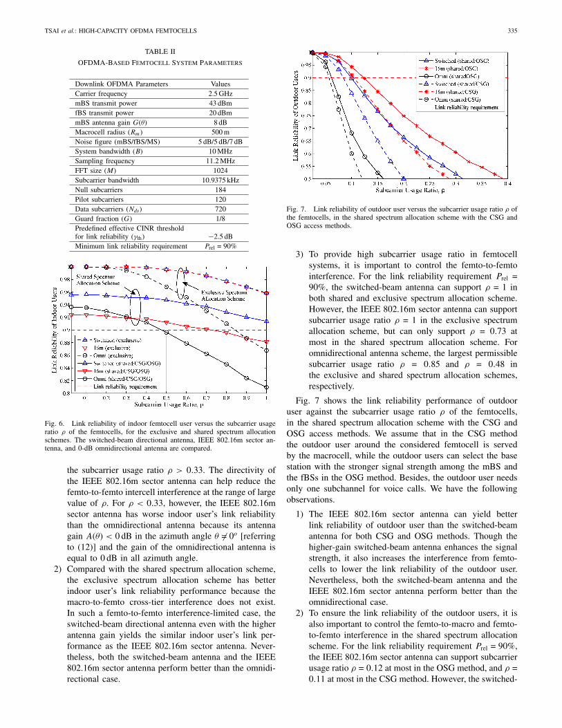
TABLE II
OFDMA-Based Femtocell System Parameters
Downlink OFDMA Parameters ValuesCarrier frequency 2.5 GHzmBS transmit power 43 dBmfBS transmit power 20 dBmmBS antenna gain G(θ) 8 dBMacrocell radius (Rm) 500 mNoise figure (mBS/fBS/MS) 5 dB/5 dB/7 dBSystem bandwidth (B) 10 MHzSampling frequency 11.2 MHzFFT size (M) 1024Subcarrier bandwidth 10.9375 kHzNull subcarriers 184Pilot subcarriers 120Data subcarriers (Nds) 720Guard fraction (G) 1/8Predefined effective CINR thresholdfor link reliability (γth) −2.5 dBMinimum link reliability requirement Prel = 90%
Fig. 6. Link reliability of indoor femtocell user versus the subcarrier usageratio ρ of the femtocells, for the exclusive and shared spectrum allocationschemes. The switched-beam directional antenna, IEEE 802.16m sector an-tenna, and 0-dB omnidirectional antenna are compared.
the subcarrier usage ratio ρ > 0.33. The directivity ofthe IEEE 802.16m sector antenna can help reduce thefemto-to-femto intercell interference at the range of largevalue of ρ. For ρ < 0.33, however, the IEEE 802.16msector antenna has worse indoor user’s link reliabilitythan the omnidirectional antenna because its antennagain A(θ) < 0 dB in the azimuth angle θ �= 0o [referringto (12)] and the gain of the omnidirectional antenna isequal to 0 dB in all azimuth angle.
2) Compared with the shared spectrum allocation scheme,the exclusive spectrum allocation scheme has betterindoor user’s link reliability performance because themacro-to-femto cross-tier interference does not exist.In such a femto-to-femto interference-limited case, theswitched-beam directional antenna even with the higherantenna gain yields the similar indoor user’s link per-formance as the IEEE 802.16m sector antenna. Never-theless, both the switched-beam antenna and the IEEE802.16m sector antenna perform better than the omnidi-rectional case.
Fig. 7. Link reliability of outdoor user versus the subcarrier usage ratio ρ ofthe femtocells, in the shared spectrum allocation scheme with the CSG andOSG access methods.
3) To provide high subcarrier usage ratio in femtocellsystems, it is important to control the femto-to-femtointerference. For the link reliability requirement Prel =90%, the switched-beam antenna can support ρ = 1 inboth shared and exclusive spectrum allocation scheme.However, the IEEE 802.16m sector antenna can supportsubcarrier usage ratio ρ = 1 in the exclusive spectrumallocation scheme, but can only support ρ = 0.73 atmost in the shared spectrum allocation scheme. Foromnidirectional antenna scheme, the largest permissiblesubcarrier usage ratio ρ = 0.85 and ρ = 0.48 inthe exclusive and shared spectrum allocation schemes,respectively.
Fig. 7 shows the link reliability performance of outdooruser against the subcarrier usage ratio ρ of the femtocells,in the shared spectrum allocation scheme with the CSG andOSG access methods. We assume that in the CSG methodthe outdoor user around the considered femtocell is servedby the macrocell, while the outdoor users can select the basestation with the stronger signal strength among the mBS andthe fBSs in the OSG method. Besides, the outdoor user needsonly one subchannel for voice calls. We have the followingobservations.
1) The IEEE 802.16m sector antenna can yield betterlink reliability of outdoor user than the switched-beamantenna for both CSG and OSG methods. Though thehigher-gain switched-beam antenna enhances the signalstrength, it also increases the interference from femto-cells to lower the link reliability of the outdoor user.Nevertheless, both the switched-beam antenna and theIEEE 802.16m sector antenna perform better than theomnidirectional case.
2) To ensure the link reliability of the outdoor users, it isalso important to control the femto-to-macro and femto-to-femto interference in the shared spectrum allocationscheme. For the link reliability requirement Prel = 90%,the IEEE 802.16m sector antenna can support subcarrierusage ratio ρ = 0.12 at most in the OSG method, and ρ =0.11 at most in the CSG method. However, the switched-
336 IEEE SYSTEMS JOURNAL, VOL. 6, NO. 2, JUNE 2012
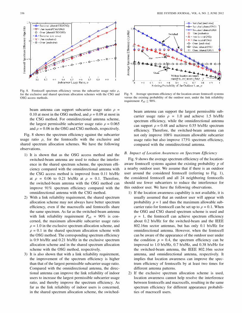
Fig. 8. Femtocell spectrum efficiency versus the subcarrier usage ratio ρ,for the exclusive and shared spectrum allocation schemes with the CSG andOSG access methods.
beam antenna can support subcarrier usage ratio ρ =0.10 at most in the OSG method, and ρ = 0.09 at most inthe CSG method. For omnidirectional antenna scheme,the largest permissible subcarrier usage ratio ρ = 0.065and ρ = 0.06 in the OSG and CSG methods, respectively.
Fig. 8 shows the spectrum efficiency against the subcarrierusage ratio ρ, for the femtocells with the exclusive andshared spectrum allocation schemes. We have the followingobservations.
1) It is shown that as the OSG access method and theswitched-beam antenna are used to reduce the interfer-ence in the shared spectrum scheme, the spectrum effi-ciency compared with the omnidirectional antenna withthe CSG access method is improved from 0.11 b/s/Hzat ρ = 0.06 to 0.21 b/s/Hz at ρ = 0.1. Therefore,the switched-beam antenna with the OSG method canimprove 91% spectrum efficiency compared with theomnidirectional antenna with the CSG method.
2) With a link reliability requirement, the shared spectrumallocation scheme may not always have better spectrumefficiency, even if the macrocells and femtocells sharethe same spectrum. As far as the switched-beam antennawith link reliability requirement Prel = 90% is con-cerned, the maximum allowable subcarrier usage ratioρ = 1.0 in the exclusive spectrum allocation scheme, andρ = 0.1 in the shared spectrum allocation scheme withthe OSG method. The corresponding spectrum efficiencyis 0.9 b/s/Hz and 0.21 b/s/Hz in the exclusive spectrumallocation scheme and in the shared spectrum allocationscheme with the OSG method, respectively.
3) It is also shown that with a link reliability requirement,the improvement of the spectrum efficiency is higherthan that of the largest permissible subcarrier usage ratio.Compared with the omnidirectional antenna, the direc-tional antenna can improve the link reliability of indoorusers to increase the largest permissible subcarrier usageratio, and thereby improve the spectrum efficiency. Asfar as the link reliability of indoor users is concerned,in the shared spectrum allocation scheme, the switched-
Fig. 9. Average spectrum efficiency of the location-aware femtocell systemsversus the existing probability of the outdoor user, under the link reliabilityrequirement Prel ≥ 90%.
beam antenna can support the largest permissible sub-carrier usage ratio ρ = 1.0 and achieve 1.5 b/s/Hzspectrum efficiency, while the omnidirectional antennacan support ρ = 0.48 and achieve 0.55 b/s/Hz spectrumefficiency. Therefore, the switched-beam antenna cannot only improve 108% maximum allowable subcarrierusage ratio but also improve 173% spectrum efficiency,compared with the omnidirectional antenna.
B. Impact of Location Awareness on Spectrum Efficiency
Fig. 9 shows the average spectrum efficiency of the location-aware femtocell systems against the existing probability p ofa nearby outdoor user. We assume that if there is an outdooruser around the considered femtocell (referring to Fig. 1),the considered femtocell and all 24 neighboring femtocellsshould use fewer subcarriers to reduce the interference forthis outdoor user. We have the following observations.
1) If the location awareness capability is not available, it isusually assumed that an outdoor user will appear withprobability p = 1 and thus the maximum allowable sub-carrier ratio for femtocell can be set up to ρ = 0.1. Whenthe OSG and CSG shared spectrum scheme is used andp = 1, the femtocell can achieve spectrum efficiencyabout 0.2 b/s/Hz for the switched-beam and the IEEE802.16m sector antennas, but has only 0.1 b/s/Hz foromnidirectional antenna. However, when the femtocellcan be aware of the appearance of the outdoor user underthe condition p = 0.4, the spectrum efficiency can beimproved to 1.0 b/s/Hz, 0.7 b/s/Hz, and 0.38 b/s/Hz forthe switched-beam antenna, the IEEE 802.16m sectorantenna, and omnidirectional antenna, respectively. Itimplies that location awareness can improve the spec-trum efficiency of femtocells by at least two times fordifferent antenna patterns.
2) If the exclusive spectrum allocation scheme is used,location awareness cannot help resolve the interferencebetween femtocells and macrocells, resulting in the samespectrum efficiency for different appearance probabili-ties of macrocell users.
TSAI et al.: HIGH-CAPACITY OFDMA FEMTOCELLS 337
Fig. 10. Maximum allowable subcarrier usage ratio of the location-awarefemtocell versus the femtocell density in the shared spectrum allocationscheme subject to the link reliability requirement Prel ≥ 90%. Scenario I:an outdoor user appears near the considered central femtocll. Scenario II:there is no outdoor user around the considered central femtrocell.
3) One can observe that location awareness capability canalso affect the choice of spectrum sharing schemesfor different antenna patterns. When the switched-beamantenna is used, the shared spectrum schemes providehigher spectrum efficiency than the exclusive schemewhen p < 0.46. The shared spectrum schemes canresult in higher spectrum efficiency than the exclusivespectrum scheme only for p < 0.19 when the IEEE802.16m sector antenna is used and for p < 0.15 whenthe omnidirectional antenna is used, respectively.
C. Impacts of Femtocell Density and Existing Probability ofOutdoor Users on Spectrum Efficiency
Fig. 10 shows the impact of femtocell density on themaximum allowable subcarrier usage ratio ρ for the location-aware femtocells with the shared spectrum location schemesubject to the link reliability requirement Prel ≥ 90%. Weconsider two scenarios. Scenarios I represents the situation thatan outdoor user appears near the considered central femtocell,and Scenario II represents the situation that an outdoor userdoes not appear near the considered central femtocell. Fromthe figure, we have the following observations.
1) In Scenario I, the femtocell density significantly affectsthe maximum allowable subcarrier usage ratio ρ whenan outdoor user appears near the considered centralfemtocell. When the femtocell density is higher than 500femtocells/km2 (the corresponding nearest separationdistance between two femtocells is dsf ≈ 45 m), themaximum allowable subcarrier usage ratio ρ shall besmaller than 0.25 to ensure the link reliability of outdoorusers.
2) In Scenario II, the maximum allowable subcarrier usageratio ρ can be increased since the outdoor user does notexist. For example, when the femtocell density reaches4500 femtocells/km2 (the corresponding nearest sepa-ration distance between two femtocells is dsf ≈ 15 m),a location-aware femtocell system has the potential toimprove ρ = 0.05 to ρ = 0.33 even with omnidirec-
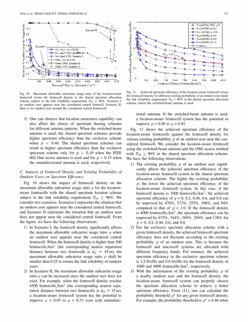
Fig. 11. Achieved spectrum efficiency of the location-aware femtocell versusthe femtocell density for different existing probability of an outdoor user underthe link reliability requirement Prel = 90% in the shared spectrum allocationscheme, where the switched-beam antenna is used.
tional antenna. If the switched-beam antenna is used,a location-aware femtocell system has the potential toimprove ρ = 0.08 to ρ = 0.85.
Fig. 11 shows the achieved spectrum efficiency of thelocation-aware femtocells against the femtocell density forvarious existing probability p of an outdoor user near the con-sidered femtocell. We consider the location-aware femtocellusing the switched-beam antenna and the OSG access methodwith Prel ≥ 90% in the shared spectrum allocation scheme.We have the following observations.
1) The existing probability p of an outdoor user signifi-cantly affects the achieved spectrum efficiency of thelocation-aware femtocell system in the shared spectrumallocation scheme. The higher the existing probabilityp, the lower the achieved spectrum efficiency of thelocation-aware femtocell system. In this case, if thefemtocell density is 1000 femtocells/km2, the achievedspectrum efficiency of p = 0, 0.2, 0.46, 0.6, and 0.8 canbe improved by 470%, 373%, 255%, 188%, and 94%compared to that of p = 1.0. If the femtocell densityis 4000 femtocells/km2, the spectrum efficiency can beimproved by 675%, 544%, 369%, 269%, and 138% forp = 0, 0.2, 0.46, 0.6, and 0.8.
2) For the exclusive spectrum allocation scheme with agiven femtocell density, the achieved femtocell spectrumefficiency does not fluctuate according to the existingprobability p of an outdoor user. This is because thefemtocell and macrocell systems are allocated withdifferent frequency bands. For instance, the achievedspectrum efficiency in the exclusive spectrum schemeis 1.2 b/s/Hz and 0.8 b/s/Hz for the femtocell density of1000 and 4000 femtocells/km2, respectively.
3) With the information of the existing probability p ofa nearby outdoor user and the femtocell density, thelocation-aware femtocell system can properly choosethe spectrum allocation scheme to achieve a betterspectrum efficiency. From (11), one can calculate theprobability threshold p∗ for any given femtocell density.For example, the probability threshold is p∗ = 0.46 when

338 IEEE SYSTEMS JOURNAL, VOL. 6, NO. 2, JUNE 2012
Fig. 12. Link reliability of indoor users versus the subcarrier usage ratio ρ ofthe femtocells, considering three antenna azimuth cases for the switched-beamantenna.
the femtocell density is 2500 femtocells/km2. If theexisting probability of a nearby outdoor user p > p∗, thefemtocell system should adopt the exclusive spectrumallocation scheme to achieve a higher spectrum effi-ciency. If p ≤ p∗, the location-aware femtocell systemcan select the shared spectrum scheme to improve thespectrum efficiency.
D. Impact of Antenna Azimuth of Femtocells on LinkReliability
Fig. 12 shows the link reliability of the indoor femtocellusers against the subcarrier usage ratio ρ. We consider threeantenna azimuth scenarios of the switched-beam femtocellsin Fig. 5. However, in this example, the largest difference inlink reliability among the three considered cases is only 2.3%.This result implies that the antenna azimuth of switched-beamfemtocell has insignificant effects on the link reliability ofthe femtocell users. Thus, it is implied that femtocells canbe deployed with random antenna azimuth.
E. Summary
The proposed design principle aims to help decide thesuitable spectrum allocation and access method for femtocells.Actually, without location awareness, it is usually assumedthat the existing probability of outdoor user is p = 1. In thissituation, to guarantee the link reliability of all indoor andoutdoor users, the conventional femtocell can only use fewersubcarriers in the shared spectrum allocation scheme or canoperate in the exclusive spectrum allocation to alleviate theinterference to the other users. Neither the shared spectrum al-location scheme nor the exclusive spectrum allocation schemeis a good option for the conventional femtocell system. On theone hand, spectrum efficiency is too low even if the directionalantennas are used to mitigate the interference to the outdoorusers in the shared spectrum allocation scheme. On the otherhand, the cost for the two times of bandwidth in the exclusivespectrum allocation scheme is too high. On the contrary, iflocation awareness is available, the shared spectrum allocationscheme can achieve higher spectrum efficiency than the exclu-sive spectrum allocation scheme as the existing probability of
TABLE III
Comparison of Various Antenna for
Location-Aware Femtocells
Average Spectrum Efficiency (b/s/Hz) of theLocation-Aware Femtocell
AntennaCategory
SpectrumAllocationSchemesand AccessMethods
Dense Ur-ban Areas(p = 0.70)
UrbanAreas(p = 0.33)
SuburbanAreas(p = 0.18)
RuralAreas(p = 0.04)
Wilderness(p = 0.01)
Shared/OSG 0.59 1.07 (Best) 1.27 (Best) 1.45(Best)
1.49 (Best)
Switched Shared/CSG 0.56 1.06 1.26 1.44 1.48Exclusive 0.9 (Best) 0.9 0.9 0.9 0.9Shared/OSG 0.47 0.78 0.90 1.02 1.04
16m Shared/CSG 044 0.77 0.89 1.02 1.04Exclusive 0.89 0.89 0.89 0.89 0.89Shared/OSG 0.22 0.40 0.47 1.53 0.55
Omni Shared/CSG 0.22 0.40 0.47 1.53 0.55Exclusive 0.48 0.48 0.48 0.48 0.48
The population densities are 3000, 1000, 500, 100, and 25 citizens/km2 inthe dense urban areas, urban areas, suburban areas, rural areas, and wildernessof Europe, respectively [28].
outdoor users is smaller than the probability threshold. Theprobability threshold can be calculated by (11) in this paper,and the existing probability of outdoor users is decided by theenvironment.
For a given environment, the location-aware femtocells canoperate in the shared spectrum allocation scheme if the exist-ing probability of outdoor users is smaller than the probabilitythreshold, or the location-aware femtocells should work inthe exclusive spectrum allocation scheme to achieve betterspectrum efficiency. In our example, when the switched-beamantenna is used, the shared spectrum scheme can providehigher spectrum efficiency than the exclusive scheme whenthe existing probability of outdoor user is p < 0.46. We alsotake some practical environments into account as example.First, according to [28], the population densities in Europe are3000, 1000, 500, 100, and 25 citizens/km2 in the dense urbanareas, urban areas, suburban areas, rural areas, and wilderness,respectively. In addition, the document [28] also showed thatonly 8% of the voice calls originate in the busy/peak hour incase the whole population are voice users. In [2], [4], [19],it was mentioned that 50% of all voice calls and 70% ofdata traffic occur indoors. In other words, only 50% of allvoice calls originate outdoors. When the femtocell densityis 2500 femtocells/km2, the region where the cluster of 25femtocells covers is 0.01 km2. The probability px that thereis not any active outdoor voice user in the region is
px =(1 − (0.1)2
)(Dp×0.08×0.5)(13)
where Dp is the corresponding population density. Therefore,the existing probability of outdoor users is the probability thatthere is at least one outdoor user exists in the region is
p = 1 − px = 1 − (1 − (0.1)2
)(Dp×0.08×0.5). (14)
Finally, we can determinate that the existing probability ofoutdoor users are p = 0.70, p = 0.33, p = 0.18, p = 0.04,and p = 0.01 for the dense urban areas, urban areas, suburbanareas, rural areas, and wilderness, respectively.

TSAI et al.: HIGH-CAPACITY OFDMA FEMTOCELLS 339
Table III shows the comparison of various antennas forlocation-aware femtocells in terms of the average spectrumefficiency. Five environments are considered in the table, andthey are the dense urban areas, urban areas, suburban areas,rural areas, and wilderness of Europe [28], respectively. Wemake a summary of the data given in the table.
1) It can be seen that the switched-beam antenna has thebest spectrum efficiency performance for the location-aware femtocells compared with the IEEE 802.16m andthe omnidirectional antennas.
2) To have better average spectrum efficiency performance,the location-aware femtocell with the switched-beam an-tenna should operate in the exclusive spectrum allocationscheme for the dense urban areas, where the existingprobability of outdoor users is p = 0.70. However,the location-aware femtocell with the switched-beamantenna can operate in the shared spectrum allocationscheme for the urban areas, suburban areas, rural ar-eas, and wilderness, where the existing probabilities ofoutdoor users are p = 0.33, p = 0.18, p = 0.04, andp = 0.01, respectively.
VI. Conclusion
In this paper, we evaluated the throughput of the OFDMAfemtocell system with the directional antenna by applyingthree techniques to reduce the interference between macrocellsand femtocells. First, the low-cost four-sector switched-beamantenna was employed to mitigate the interference becauseof the narrow-beam pattern. Second, the partial usage ofsubcarriers approach ensured the link reliability of all usersby adjusting the number of OFDMA subcarriers used by afemtocell. Third, the location awareness was applied to thefemtocell systems for improving spectrum efficiency. Combin-ing these elements, a location-aware femtocell achieved higherspectrum efficiency than the conventional femtocells using thedirectional antennas, under the link reliability requirement.
The contributions of this paper are described as follows.First, we provided a useful principle for femtocell networkplanning to select the appropriate spectrum allocation schemeand access method to improve spectrum efficiency. Second,we found that the location awareness capability was essentialto the success of improving the femtocell spectrum efficiencybecause using the directional antenna was not enough toguarantee the link reliability of all indoor and outdoor users.Third, the impacts of spectrum allocation, access method, fem-tocell density, and directional antenna on link reliability andspectrum efficiency of OFDMA femtocells were investigated,and had some important observations. For example, we foundthat the shared spectrum scheme may not always have betterspectrum efficiency than the exclusive spectrum scheme underthe link reliability requirement.
Future Works: In summary, the design principles pro-vided in this paper can help decide the suitable spectrumallocation and access method for the femtocells. There aresome interesting research topics that can be extended fromthis paper, including multiple-user access and subchannelallocation in switch-beam OFDMA femtocells.
References
[1] H. Claussen, L. T. W. Ho, and L. G. Samuel, “An overview of thefemtocell concept,” Bell Labs Tech. J., vol. 13, no. 1, pp. 221–246,2008.
[2] V. Chandrasekhar and J. G. Andrews, “Femtocell networks: A survey,”IEEE Commun. Mag., vol. 46, no. 9, pp. 59–67, Sep. 2008.
[3] S.-P. Yeh, S. Talwar, S.-C. Lee, and H. Kim, “WiMAX femtocells:A perspective on network architecture, capacity, and coverage,” IEEECommun. Mag., vol. 46, no. 10, pp. 58–65, Oct. 2008.
[4] D. Lopez-Perez, A. Valcarce, G. de la Roche, and J. Zhang, “OFDMAfemtocells: A roadmap on interference avoidance,” IEEE Commun.Mag., vol. 47, no. 9, pp. 41–48, Sep. 2009.
[5] R. Y. Kim, J. S. Kwak, and K. Etemad, “WiMAX femtocell: Require-ments, challenges, and solutions,” IEEE Commun. Mag., vol. 47, no. 9,pp. 84–91, Sep. 2009.
[6] V. Chandrasekhar, J. G. Andrews, T. Muharemovic, Z. Shen,and A. Gatherer, “Power control in two-tier femtocell networks,”IEEE Trans. Wireless Commun., vol. 8, no. 8, pp. 4316–4328,Aug. 2009.
[7] G. de la Roche, A. Valcarce, D. Lopez-Perez, and J. Zhang, “Accesscontrol mechanisms for femtocells,” IEEE Commun. Mag., vol. 48, no. 1,pp. 33–39, Jan. 2010.
[8] P. Xia, V. Chandrasekhar, and J. G. Andrews, “Open vs. closed accessfemtocell in the uplink,” IEEE Trans. Wireless Commun., vol. 9, no. 12,pp. 3798–3809, Dec. 2010.
[9] H. Zeng, C. Zhu, and W.-P. Chen, “System performance of self-organizing network algorithm in WiMAX femtocells,” in Proc. Int.WICON, no. 25. Nov. 2008, pp. 1–9.
[10] V. Chandrasekhar and J. G. Andrews, “Spectrum allocation in tieredcellular networks,” IEEE Trans. Commun., vol. 57, no. 10, pp. 3059–3068, Oct. 2009.
[11] C. Lee, J.-H. Huang, and L.-C. Wang, “Distributed channel selectionprinciples for femtocells with two-tier interference,” in Proc. IEEE VTC,May 2010, pp. 1–5.
[12] C.-H. Ko and H.-Y. Wei, “On-demand resource-sharing mechanismdesign in two-tier OFDMA femtocell networks,” IEEE Trans. VehicularTechnol., vol. 60, no. 3, pp. 1059–1071, Mar. 2011.
[13] S.-Y. Lien, C.-C. Tseng, K.-C. Chen, and C.-W. Su, “Cognitive radioresource management for QoS guarantees in autonomous femtocellnetworks,” in Proc. IEEE ICC, May 2010, pp. 1–6.
[14] S.-Y. Lien, Y.-Y. Lin, and K.-C. Chen, “Cognitive and game-theoreticalradio resource management for autonomous femtocells with QoS guar-antees,” IEEE Trans. Wireless Commun., vol. 10, no. 7, pp. 2196–2206,Jul. 2011.
[15] V. Chandrasekhar and J. G. Andrews, “Uplink capacity and interfer-ence avoidance for two-tier femtocell networks,” IEEE Trans. WirelessCommun., vol. 8, no. 7, pp. 3498–3509, Jul. 2009.
[16] H. Claussen, F. Pivit, and L. T. W. Ho, “Self-optimization of femtocellcoverage to minimize the increase in core network mobility signalling,”Bell Labs Tech. J., vol. 14, no. 2, pp. 155–184, 2009.
[17] S.-G. Josep and W. H. Chin, “Performance of an LTE femtocell basestation employing uplink antenna selection,” in Proc. WiAd, Jun. 2011,pp. 224–229.
[18] N.-D. Dao, Y. Sun, and W. H. Chin, “Receive antenna selectiontechniques for femtocell uplink interference mitigation,” in Proc. IEEEInt. Symp. PIMRC Workshops, Sep. 2010, pp. 180–184.
[19] Y. Jeong, H. Kim, B.-S. Kim, and H. Choo, “Avoidance of co-channel in-terference using switched parasitic array antenna in femtocell networks,”in Proc. ICCSA, vol. 6018. 2010, pp. 158–167.
[20] A.-H. Tsai, J.-H. Huang, L.-C. Wang, and R.-B. Hwang, “High capacityfemtocells with directional antennas,” in Proc. IEEE WCNC, Apr. 2010,pp. 1–6.
[21] R. Srinivasan and S. Hamiti, “IEEE 802.16m system description docu-ment (SDD),” IEEE 802.16 Broadband Wireless Access Working Group,Tech. Rep. IEEE 802.16m-09/0034r2, Sep. 2009.
[22] V. Erceg, L. Schumacher, P. Kyritsi, A. Molisch, D. S. Baum, A. Y.Gorokhov, C. Oestges, C. Lanzl, V. J. Rhodes, J. Medbo, D. Michelson,M. Webster, E. Jacobsen, D. Cheung, Q. Li, C. Prettie, M. Ho, S.Howard, B. Bjerke, K. Yu, L. Jengx, A. Jagannatham, N. Tal, S. Valle,and A. Poloni, “Indoor MIMO WLAN channel models,” IEEE P802.11Wireless LANs, Tech. Rep. IEEE 802.11-03/871r1, Nov. 2003.
[23] V. Erceg, K. V. S. Hari, M. S. Smith, D. S. Baum, K. P. Sheikh,C. Tappenden, J. M. Costa, C. Bushue, A. Sarajedini, R. Schwartz,D. Branlund, T. Kaitz, and D. Trinkwon, “Channel models for fixedwireless applications,” IEEE 802.16 Broadband Wireless Access Work-ing Group, Tech. Rep. IEEE 802.16.3c-01/29r4, Jul. 2001.

340 IEEE SYSTEMS JOURNAL, VOL. 6, NO. 2, JUNE 2012
[24] R. Yaniv, D. Stopler, T. Kaitz, and K. Blum, “CINR measurements usingthe EESM method,” IEEE 802.16 Broadband Wireless Access WorkingGroup, Tech. Rep. IEEE C802.16e-05/141, Mar. 2005.
[25] J. G. Andrews, A. Ghosh, and R. Muhamed, Fundamentals of WiMAX.Englewood Cliffs, NJ: Prentice-Hall, 2007.
[26] R. Srinivasan, J. Zhuang, L. Jalloul, R. Novak, and J. Park, “IEEE802.16 m evaluation methodology document (EMD),” IEEE 802.16Broadband Wireless Access Working Group, Tech. Rep. IEEE 802.16m-08/004r4, Nov. 2008.
[27] WiMAX Forum, “WiMAX system evaluation methodology,” Version2.1, Jul. 2008.
[28] M. A. Imran, E. Katranaras, G. Auer, O. Blume, V. Giannini, I. Godor,Y. Jading, M. Olsson, D. Sabella, P. Skillermark, and W. Wajda, “Energyefficiency analysis of the reference systems, areas of improvementsand target breakdown,” Energy Aware Radio and neTwork tecHnologies(EARTH), Tech. Rep. INFSO-ICT-247733 EARTH Deliverable D2.3,Nov. 2010.
Ang-Hsun Tsai (S’09) received the B.S. degree inelectrical engineering from the Chung Cheng In-stitute of Technology, National Defense University,Taoyuan, Taiwan, in 1998, and the M.S. degree inelectro-optical engineering from the National SunYat-Sen University, Kaohsiung, Taiwan, in 2005.He is currently pursuing the Ph.D. degree fromthe Department of Electrical Engineering, NationalChiao Tung University, Hsinchu, Taiwan.
His current research interests include femtocellnetworks, heterogeneous machine-type communica-
tions networks, and radio resource management.Mr. Tsai was elected an Honorary Member of the Phi Tau Phi Scholastic
Honor Society of the Republic of China by National Sun Yet-Sen Universityin 2005.
Li-Chun Wang (S’92–M’96–SM’06–F’11) receivedthe B.S. degree from the National Chiao Tung Uni-versity, Hsinchu, Taiwan, in 1986, the M.S. degreefrom the National Taiwan University, Taipei, Taiwan,in 1988, and the M.Sc. and Ph.D. degrees from theGeorgia Institute of Technology, Atlanta, in 1995and 1996, respectively, all in electrical engineer-ing.
From 1990 to 1992, he was with the Telecommu-nications Laboratories of the Ministry of Transporta-tions and Communications in Taiwan (currently, the
Telecom Laboratories of Chunghwa Telecom Company, Taipei). In 1995, hewas with Bell Northern Research of Northern Telecom, Inc., Richardson,TX. From 1996 to 2000, he was a Senior Technical Staff Member withthe Wireless Communications Research Department, AT&T Laboratories,Austin, TX. In August 2000, he became an Associate Professor with theDepartment of Electrical Engineering, National Chiao Tung University, wherehe is currently a Full Professor since 2005. He has published over 150 journaland international conference papers. He currently holds nine U.S. patents. Hiscurrent research interests include radio resource management and cross-layeroptimization techniques for wireless systems, heterogeneous wireless networkdesigns, and cloud computing for mobile applications.
Dr. Wang was a co-recipient (with G. L. Stuber and C.-T. Lea) of the 1997IEEE Jack Neubauer Best Paper Award for his paper “Architecture design,frequency planning, and performance analysis for a microcell/macrocelloverlaying system,” published in the IEEE Transactions on Vehicular
Technology (vol. 46, no. 4, pp. 836–848, Nov. 1997). He was an AssociateEditor of the IEEE Transactions on Wireless Communications from2001 to 2005, the Guest Editor of the Special Issue on “Mobile com-puting and networking” for the IEEE Journal on Selected Areas in
Communications in 2005 and “Radio resource management and protocolengineering in future IEEE broadband networks” for the IEEE Wireless
Communications Magazine in 2006.
Jane-Hwa Huang (M’09) received the B.S., M.S.,and Ph.D. degrees in electrical engineering from theNational Cheng Kung University, Tainan, Taiwan, in1994, 1996, and 2003, respectively.
He joined the Department of Communication En-gineering, National Chiao Tung University, Hsinchu,Taiwan, as a Post-Doctoral Researcher from 2004 toJanuary 2006, where he later became a ResearchAssistant Professor. Since August 2009, he hasbeen an Assistant Professor with the Department ofElectrical Engineering, National Chi Nan University,
Nantou, Taiwan. His current research interests include wireless networks,green communications, wireless multihop communications, and radio resourcemanagement.
Ruey-Bing Hwang (M’96–SM’06) was born inNantou, Taiwan, on January 20, 1967. He receivedthe B.S. degree in communication engineering andthe Ph.D. degree from the Institute of Electronics,National Chiao Tung University, Hsinchu, Taiwan,in 1990 and 1996, respectively.
He is currently a Professor with the Department ofElectrical Engineering, National Chiao Tung Univer-sity. His current research interests include periodicstructures, photonic crystals, metamaterials, antennadesigns, and electromagnetic compatibility.