IEEE Std 1101.1-1998 Revision of IEEE Std 1101.1-1991 IEEE ...
52
The Institute of Electrical and Electronics Engineers, Inc. 345 East 47th Street, New York, NY 10017-2394, USA Copyright ' 1998 by the Institute of Electrical and Electronics Engineers, Inc. All rights reserved. Published 18 December 1998. Printed in the United States of America. Print: ISBN 0-7381-1449-9 SH94691 PDF: ISBN 0-7381-1450-2 SS94691 No part of this publication may be reproduced in any form, in an electronic retrieval system or otherwise, without the prior written permission of the publisher. IEEE Std 1101.1-1998 (Revision of IEEE Std 1101.1-1991) IEEE Standard for Mechanical Core Specications for Microcomputers Using IEC 60603-2 Connectors Sponsor Microprocessor and Microcomputer Standards Subcommittee of the IEEE Computer Society Approved 28 September 1998 IEEE-SA Standards Board Abstract: The basic dimensions of a range of modular subracks conforming to IEC 60297-3 (1984- 01) and IEC 60297-4 (1995-03) for mounting in equipment according to IEC 60297-1 (1986-09) and ANSI/EIA 310-D-1992, together with the basic dimensions of a compatible range of plug-in units, printed boards, and backplanes, are covered. The dimensions and tolerances necessary to ensure mechanical function compatibility are provided. This standard offers total system integration guide- lines with attendant advantages, such as reduction in design and development time, manufacturing cost savings, and distinct marketing advantages. Keywords: compatibility, mechanical interchangeability, plug-in units, subracks
Transcript of IEEE Std 1101.1-1998 Revision of IEEE Std 1101.1-1991 IEEE ...

The Institute of Electrical and Electronics Engineers, Inc.345 East 47th Street, New York, NY 10017-2394, USA
Copyright © 1998 by the Institute of Electrical and Electronics Engineers, Inc.All rights reserved. Published 18 December 1998. Printed in the United States of America.
Print:
ISBN 0-7381-1449-9 SH94691
PDF:
ISBN 0-7381-1450-2 SS94691
No part of this publication may be reproduced in any form, in an electronic retrieval system or otherwise, without the prior written permission of the publisher.
IEEE Std 1101.1-1998
(Revision ofIEEE Std 1101.1-1991)
IEEE Standard for Mechanical Core SpeciÞcations for Microcomputers Using IEC 60603-2 Connectors
Sponsor
Microprocessor and Microcomputer Standards Subcommitteeof theIEEE Computer Society
Approved 28 September 1998
IEEE-SA Standards Board
Abstract:
The basic dimensions of a range of modular subracks conforming to IEC 60297-3 (1984-01) and IEC 60297-4 (1995-03) for mounting in equipment according to IEC 60297-1 (1986-09) andANSI/EIA 310-D-1992, together with the basic dimensions of a compatible range of plug-in units,printed boards, and backplanes, are covered. The dimensions and tolerances necessary to ensuremechanical function compatibility are provided. This standard offers total system integration guide-lines with attendant advantages, such as reduction in design and development time, manufacturingcost savings, and distinct marketing advantages.
Keywords:
compatibility, mechanical interchangeability, plug-in units, subracks

IEEE Standards
documents are developed within the IEEE Societies and the Standards Coordinat-ing Committees of the IEEE Standards Association (IEEE-SA) Standards Board. Members of thecommittees serve voluntarily and without compensation. They are not necessarily members of theInstitute. The standards developed within IEEE represent a consensus of the broad expertise on thesubject within the Institute as well as those activities outside of IEEE that have expressed an inter-est in participating in the development of the standard.
Use of an IEEE Standard is wholly voluntary. The existence of an IEEE Standard does not implythat there are no other ways to produce, test, measure, purchase, market, or provide other goods andservices related to the scope of the IEEE Standard. Furthermore, the viewpoint expressed at thetime a standard is approved and issued is subject to change brought about through developments inthe state of the art and comments received from users of the standard. Every IEEE Standard is sub-jected to review at least every Þve years for revision or reafÞrmation. When a document is morethan Þve years old and has not been reafÞrmed, it is reasonable to conclude that its contents,although still of some value, do not wholly reßect the present state of the art. Users are cautioned tocheck to determine that they have the latest edition of any IEEE Standard.
Comments for revision of IEEE Standards are welcome from any interested party, regardless ofmembership afÞliation with IEEE. Suggestions for changes in documents should be in the form of aproposed change of text, together with appropriate supporting comments.
Interpretations: Occasionally questions may arise regarding the meaning of portions of standards asthey relate to speciÞc applications. When the need for interpretations is brought to the attention ofIEEE, the Institute will initiate action to prepare appropriate responses. Since IEEE Standards rep-resent a consensus of all concerned interests, it is important to ensure that any interpretation hasalso received the concurrence of a balance of interests. For this reason, IEEE and the members of itssocieties and Standards Coordinating Committees are not able to provide an instant response tointerpretation requests except in those cases where the matter has previously received formalconsideration.
Comments on standards and requests for interpretations should be addressed to:
Secretary, IEEE-SA Standards Board445 Hoes LaneP.O. Box 1331Piscataway, NJ 08855-1331USA
Authorization to photocopy portions of any individual standard for internal or personal use isgranted by the Institute of Electrical and Electronics Engineers, Inc., provided that the appropriatefee is paid to Copyright Clearance Center. To arrange for payment of licensing fee, please contactCopyright Clearance Center, Customer Service, 222 Rosewood Drive, Danvers, MA 01923 USA;(978) 750-8400. Permission to photocopy portions of any individual standard for educational class-room use can also be obtained through the Copyright Clearance Center.
Note: Attention is called to the possibility that implementation of this standard mayrequire use of subject matter covered by patent rights. By publication of this standard,no position is taken with respect to the existence or validity of any patent rights inconnection therewith. The IEEE shall not be responsible for identifying patents forwhich a license may be required by an IEEE standard or for conducting inquiries intothe legal validity or scope of those patents that are brought to its attention.

Copyright © 1998 IEEE. All rights reserved.
iii
Introduction
(This introduction is not a part of IEEE Std 1101.1-1998, IEEE Standard for Mechanical Core SpeciÞcations for Micro-computers Using IEC 60603-2 Connectors.)
With the introduction of international (IEC) microcomputer architectures based on the ÒEuroboard form fac-tor,Ó the IEEE Computer Society Technical Committee on Microprocessors and Microcomputers found itappropriate to form a separate IEEE standard to expand upon the IEC 60297 series of standards, Dimensionsof mechanical structures of the 482.6 mm (19 in) series. (See Clause 3 of this standard.)
This standard provides design engineers with the dimensions and tolerances necessary to ensure mechanicalfunction compatibility. This standard also provides environmental speciÞcations as an addendum to IEC60297-3 (1984-01).
This mechanical standard offers total system integration guidelines. It offers advantages such as reduction indesign and development time, manufacturing cost savings, and distinct marketing advantages.
This standard covers standardized dimensions of a range of modular subracks and a compatible range ofplug-in units, printed boards, backplanes, and connectors.
This standard was revised from IEEE Std 1101.1-1991.
At the time that the revision was completed, the P1101.1 Working Group had the following membership:
Eike Waltz,
Chair
Frank Hom,
Secretary
The following persons were on the balloting committee that approved this document for submission to theIEEE-SA Standards Board:
Ralf BehrensMartin BlakeRobert DowningJean-Jacques Dumont
Wayne P. FischerTad KubicPaul MazuraMichael MunroeJoe P. Norris
Elwood T. ParsonsHolly SherÞnskyMichael G. ThompsonSue Wong
Ghassan A. AbbasMalcolm J. AirstRay S. AldermanKeith D. AnthonyEdmund H. BaulsirMartin BlakeRalf BokaemperDavid BrearleyCharles BrillC. H. ChenJean-Jacques Dumont
Jean Paul EmardWayne P. FischerKenneth C. HeckRoger HinsdaleFrank HomJing KwokConrad A. LaurvickGerald E. LawsRollins LinserGary S. ManchesterJoseph R. MarshallThanos Mentzelopoulos
Gene E. MilliganKlaus-Dieter MuellerMichael MunroeJoe P. NorrisPeter G. OdellElwood T. ParsonsHermann H. StrassMichael G. ThompsonRobert C. TripiBruce WallaceDavid L. Wright

iv
Copyright © 1998 IEEE. All rights reserved.
The Þnal conditions for approval of this standard were met on 28 September 1998. This standard was condi-tionally approved by the IEEE-SA Standards Board on 16 September 1998, with the following membership:
Richard J. Holleman,
Chair
Donald N. Heirman,
Vice Chair
Judith Gorman,
Secretary
*Member Emeritus
Catherine Berger
IEEE Standards Project Editor
Satish K. AggarwalClyde R. CampJames T. CarloGary R. EngmannHarold E. EpsteinJay Forster*Thomas F. GarrityRuben D. Garzon
James H. GurneyJim D. IsaakLowell G. JohnsonRobert KennellyE. G. ÒAlÓ KienerJoseph L. KoepÞnger*Stephen R. LambertJim LogothetisDonald C. Loughry
L. Bruce McClungLouis-Fran�ois PauRonald C. PetersenGerald H. PetersonJohn B. PoseyGary S. RobinsonHans E. WeinrichDonald W. Zipse
Copyright © 1998 IEEE. All rights reserved.
v
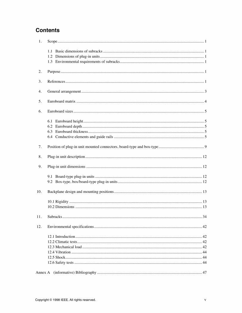
Contents
1. Scope.................................................................................................................................................... 1
1.1 Basic dimensions of subracks ...................................................................................................... 11.2 Dimensions of plug-in units......................................................................................................... 11.3 Environmental requirements of subracks..................................................................................... 1
2. Purpose................................................................................................................................................. 1
3. References............................................................................................................................................ 1
4. General arrangement............................................................................................................................ 3
5. Euroboard matrix ................................................................................................................................. 4
6. Euroboard sizes.................................................................................................................................... 5
6.1 Euroboard height.......................................................................................................................... 56.2 Euroboard depth........................................................................................................................... 56.3 Euroboard thickness..................................................................................................................... 56.4 Conductive elements and guide rails ........................................................................................... 5
7. Position of plug-in unit mounted connectors, board-type and box-type.............................................. 9
8. Plug-in unit description...................................................................................................................... 12
9. Plug-in unit dimensions ..................................................................................................................... 12
9.1 Board-type plug-in units ............................................................................................................ 129.2 Box-type, box/board-type plug-in units..................................................................................... 12
10. Backplane design and mounting positions......................................................................................... 13
10.1 Rigidity ...................................................................................................................................... 1310.2 Dimensions ................................................................................................................................ 13
11. Subracks............................................................................................................................................. 34
12. Environmental specifications............................................................................................................. 42
12.1 Introduction................................................................................................................................ 4212.2 Climatic tests.............................................................................................................................. 4212.3 Mechanical load ......................................................................................................................... 4212.4 Vibration .................................................................................................................................... 4412.5 Shock.......................................................................................................................................... 4412.6 Safety tests ................................................................................................................................. 44
Annex A (informative) Bibliography .......................................................................................................... 47

Copyright © 1998 IEEE. All rights reserved.
1
IEEE Standard for Mechanical Core SpeciÞcations for Microcomputers Using IEC 60603-2 Connectors
1. Scope
1.1 Basic dimensions of subracks
This standard covers the basic dimensions of a range of modular subracks conforming to IEC 60297-3(1984-01) and IEC 60297-4 (1995-03) for mounting in equipment according to IEC 60297-1 (1986-09) andANSI/EIA 310-D-1992, together with the basic dimensions of a compatible range of plug-in units, printedboards, and backplanes.
1.2 Dimensions of plug-in units
This standard will give the dimensions of associated plug-in units and connector-mounting details togetherwith applicable detail dimensions of the subrack.
1.3 Environmental requirements of subracks
This standard will state environmental requirements of subracks and their associated plug-in units.
2. Purpose
The purpose of this standard is the speciÞcation of dimensions that will ensure the mechanical interchange-ability and environmental requirements of subracks and of plug-in units.
3. References
The following publications shall be used in conjunctions with this standard. When they are superseded by anapproved revision, the revision shall apply.
ANSI/EIA 310-D-1992: Racks, Panels, and Associated Equipment.
1
1
ANSI publications are available from the Sales Department, American National Standards Institute, 11 West 42nd Street, 13th Floor,New York, NY 10036, USA (www.ansi.org/).

IEEEStd 1101.1-1998 IEEE STANDARD FOR MECHANICAL CORE SPECIFICATIONS
2
Copyright © 1998 IEEE. All rights reserved.
CFR (Code of Federal Regulations), Title 47: Telecommunications, Part 15J, published by OfÞce of the Fed-eral Register (FCC Rules and Regulations are contained within this document).
2
IEC 60068-2-1 (1990-05), Environmental testingÑPart 2: Tests. Tests A: Cold.
3
IEC 60068-2-2 (1974-01), Environmental testingÑPart 2: Tests. Test B: Dry Heat.
IEC 60068-2-6 (1995-03), Environmental testingÑPart 2: Tests. Test Fc: Vibration (sinusoidal).
IEC 60068-2-11 (1981-01), Environmental testingÑPart 2: Tests. Test Ka: Salt mist.
IEC 60068-2-27 (1987-06), Environmental testingÑPart 2: Tests. Test Ea and guidance: Shock.
IEC 60097 (1991-05), Grid systems for printed circuits.
IEC 60249-2-1 (1985-01), Base materials for printed circuits. Part 2: SpeciÞcations. SpeciÞcation No. 1:Phenolic cellulose paper copper-clad laminated sheet, high electrical quality.
IEC 60249-2-2 (1985-01), Base materials for printed circuits. Part 2: SpeciÞcations. SpeciÞcation No. 2:Phenolic cellulose paper copper-clad laminated sheet, economic quality.
IEC 60249-2-3 (1987-04), Base materials for printed circuits. Part 2: SpeciÞcations. SpeciÞcation No. 3:Epoxide cellulose paper copper-clad laminated sheet of deÞned ßammability (vertical burning test).
IEC 60249-2-4 (1987-06), Base materials for printed circuits. Part 2: SpeciÞcations. SpeciÞcation No. 4:Epoxide woven glass fabric copper-clad laminated sheet, general purpose grade.
IEC 60249-2-5 (1987-06), Base materials for printed circuits. Part 2: SpeciÞcations. SpeciÞcation No. 5:Epoxide woven glass fabric copper-clad laminated sheet of deÞned ßammability (vertical burning test).
IEC 60297-1 (1986-09), Dimensions of mechanical structures of the 482.6 mm (19 in) series. Part 1: Panelsand racks.
IEC 60297-3 (1984-01), Dimensions of mechanical structures of the 482.6 mm (19 in) series. Part 3: Sub-racks and associated plug-in units.
IEC 60297-4 (1995-03), Mechanical structures of electronic equipmentÑDimensions of mechanical struc-tures of the 482.6 mm (19 in) series. Part 4: Subracks and associated plug-in unitsÑAdditional dimensions.
IEC 60603-2 (1995-09), Connectors for frequencies below 3 MHz for use with printed boardsÑPart 2:Detail speciÞcation for two-part connectors with assessed quality, for printed boards, for basic grid of2.54 mm (0.1 in), with common mounting features.
IEC 60651 (1979-01), Sound level meters.
IEC 60707 (1981-01), Methods of test for the determination of the ßammability of solid electrical insulatingmaterials when exposed to an igniting source.
IEC 61010-1 (1990-09), Safety requirements for electrical equipment for measurement, control, and labora-tory useÑPart 1: General requirements.
4
2
CFR publications are available from the Superintendent of Documents, U.S. Government Printing OfÞce, P.O. Box 37082, Washing-ton, DC 20013-7082, USA.
3
IEC publications are available from the Sales Department of the International Electrotechnical Commission, Case Postale 131, 3, ruede Varemb�, CH-1211, Gen�ve 20, Switzerland/Suisse (www.iec.ch/). IEC publications are also available from the Sales Department,American National Standards Institute, 11 West 42nd Street, 13th Floor, New York, NY 10036, USA (www.ansi.org/).
4
IEC 61010-1 (1990-09) replaces withdrawn standard IEC 60348 (1978).

IEEEFOR MICROCOMPUTERS USING IEC 60603-2 CONNECTORS Std 1101.1-1998
Copyright © 1998 IEEE. All rights reserved.
3
IEEE Std 1101.10-1996, IEEE Standard for Additional Mechanical SpeciÞcations for MicrocomputersUsing the IEEE 1101.1-1991 Equipment Practice.
5
IEEE 1101.11-1998, IEEE Standard for Mechanical Rear Plug-in Units SpeciÞcations for MicrocomputersUsing the IEEE 1101.1 and the IEEE 1101.10 Equipment Practice.
4. General arrangement
Subracks may be mounted one above another or in combination with suitable instruments and panels inequipment complying with the rack and panel dimensions given in IEC 60297-1 (1986-09) and ANSI/EIA310-D-1992. See Figure 1.
5
IEEE publications are available from the Institute of Electrical and Electronics Engineers, 445 Hoes Lane, P.O. Box 1331, Piscataway,NJ 08855-1331, USA (www.standards.ieee.org/).
Subrack
Box-TypePlug-In Units
Board-TypeBox-TypePlug-in Units
Front Panel
Rack/CabinetVertical Member
NOTES1ÑGenerally, subracks are equipped with printed board or rack-and-panel-type connectors at the rear side, and haveguides for locating or supporting, or both, printed boards or plug-in units.2ÑIn principle, the connector is mounted on the right side of the printed board as viewed from the front of the sub-rack.3ÑTable 5 deÞnes the dimensions required for mechanical interchangeability of plug-in units.4ÑThe drawings in this standard are not intended to indicate details of design. All dimensions are given in millime-ters (with inches in parentheses).5ÑAll drawings in this standard are shown in the Þrst angle projection according to ISO 1101: 1983 [B3].6ÑTerminology is as per IEC 60917-1 (1998-09) [B2] and IEC 60050 [B1].
Figure 1ÑGeneral arrangement
IEEEStd 1101.1-1998 IEEE STANDARD FOR MECHANICAL CORE SPECIFICATIONS
4
Copyright © 1998 IEEE. All rights reserved.
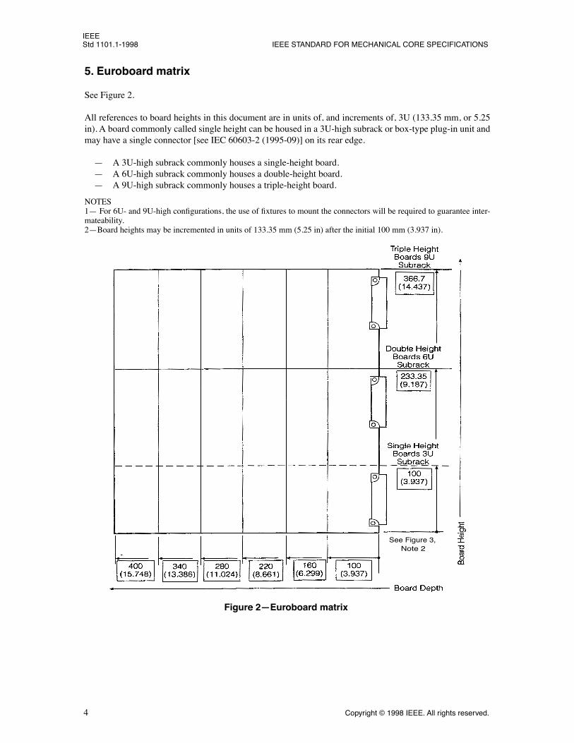
5. Euroboard matrix
See Figure 2.
All references to board heights in this document are in units of, and increments of, 3U (133.35 mm, or 5.25in). A board commonly called single height can be housed in a 3U-high subrack or box-type plug-in unit andmay have a single connector [see IEC 60603-2 (1995-09)] on its rear edge.
Ñ A 3U-high subrack commonly houses a single-height board.Ñ A 6U-high subrack commonly houses a double-height board.Ñ A 9U-high subrack commonly houses a triple-height board.
NOTES1Ñ For 6U- and 9U-high conÞgurations, the use of Þxtures to mount the connectors will be required to guarantee inter-mateability.2ÑBoard heights may be incremented in units of 133.35 mm (5.25 in) after the initial 100 mm (3.937 in).
Figure 2ÑEuroboard matrix
See Figure 3, Note 2

IEEEFOR MICROCOMPUTERS USING IEC 60603-2 CONNECTORS Std 1101.1-1998
Copyright © 1998 IEEE. All rights reserved.
5
6. Euroboard sizes
Table 1 and Table 2 show a selected range of Euroboard sizes from IEC 60297-3 (1984-01).
6.1 Euroboard height
6.2 Euroboard depth
6.3 Euroboard thickness
The thickness of printed boards of plug-in units shall be 1.6 ± 0.2 mm (0.063 ± 0.008 in) in the area of theguide rails [clearance for guide rails
³
2.5 mm (0.098 in)]. (See Figure 3.) See the IEC 60249-2-series forother printed board thicknesses and tolerances.
6.4 Conductive elements and guide rails
Conductive elements are not to extend beyond the usable component space on the outer planes. Printed cir-cuits and components shall be placed on the board in accordance with their electrical features.
NOTEÑThe clearance area for guide rails may be used to provide conductivity between the subrack and the boards inorder to reduce EMI/RFI emissions, provide electrostatic discharge (ESD) contact, or to provide heat sinking capabilityfor the board.
Table 1ÑEuroboard height
Reference-U 3 6 9
Printed board heightH
b
+0/Ð0.3(+0/Ð0.012)see Clause 5, Note 2
100.00 mm(3.937 in)
233.35 mm(9.187 in)
366.70 mm(14.437 in)
Table 2ÑEuroboard depth
Printed board depthD
b
+0/Ð0.3(+0/Ð0.012)
100 mm(3.937 in)
160 mm(6.299 in)
220 mm(8.661 in)
280 mm(11.024 in)
340 mm(13.386 in)
400 mm(15.748 in)
D
a
±0.1(±0.004)
93.67 mm(3.688 in)
153.67 mm(6.050 in)
213.67 mm(8.412 in)
273.67 mm(10.774 in)
333.67 mm(13.137 in)
393.67 mm(15.499 in)

IEEEStd 1101.1-1998 IEEE STANDARD FOR MECHANICAL CORE SPECIFICATIONS
6
Copyright © 1998 IEEE. All rights reserved.
Figure 3ÑSingle-height boards, component side 1 view
NOTES1ÑFor board thickness, see 6.3.2ÑThis connector pattern refers to Type C connectors as speciÞed in IEC 60603-2 (1995-09), which does not indi-cate tolerance. Recommended IEEE 1101.1 tolerance is +0.05 mm (+0.002 in).3ÑSee IEC 60097 (1991-05).
Component Side 1
Hb
Da
Db
IEEEFOR MICROCOMPUTERS USING IEC 60603-2 CONNECTORS Std 1101.1-1998
Copyright © 1998 IEEE. All rights reserved.
7
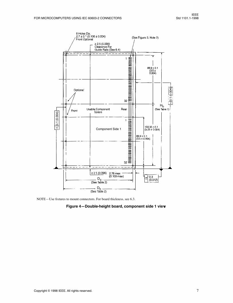
NOTEÑUse Þxtures to mount connectors. For board thickness, see 6.3.
Figure 4ÑDouble-height board, component side 1 view
Component Side 1
Da
Db
Hb

IEEEStd 1101.1-1998 IEEE STANDARD FOR MECHANICAL CORE SPECIFICATIONS
8
Copyright © 1998 IEEE. All rights reserved.
NOTEÑUse Þxtures to mount connectors. For board thickness, see 6.3
Figure 5ÑTriple-height board, component side 1 view
Component Side 1
Da
Db
Hb

IEEEFOR MICROCOMPUTERS USING IEC 60603-2 CONNECTORS Std 1101.1-1998
Copyright © 1998 IEEE. All rights reserved.
9
7. Position of plug-in unit mounted connectors, board-type and box-type
Table 3ÑPosition of plug-in mounted connectors, board/box-type
Connector type[see IEC 60603-2 (1995-09)]
L
1
L
2
B + C (see Figure 6) 85.2 + 0.2 Ð 0(3.354 + 0.008/Ð0)
Ñ
Q + R (see Figure 7) Ñ 85.2 Ð 0.2/+0(3.354 Ð 0.008/+0)
Table 4ÑPosition of plug-in mounted unit connectors
Reference-U
a
a
Subracks are dimensioned in height of U, 1U = 44.45 mm (1.75 in). See IEC60297-1 (1986-09) and ANSI/EIA 310-D-1992.
3 6 9
b
1
Ñ 133.35 mm (5.25 in)
133.35 mm (5.25 in)
b
2
Ñ Ñ 133.35 mm (5.25 in)

IEEEStd 1101.1-1998 IEEE STANDARD FOR MECHANICAL CORE SPECIFICATIONS
10
Copyright © 1998 IEEE. All rights reserved.
NOTEÑFixtures are required when mounting connectors on double- and triple-height boards.
Figure 6ÑPosition of connectors on plug-in units
Hb
Hb
L1
L1
IEEEFOR MICROCOMPUTERS USING IEC 60603-2 CONNECTORS Std 1101.1-1998
Copyright © 1998 IEEE. All rights reserved.
11
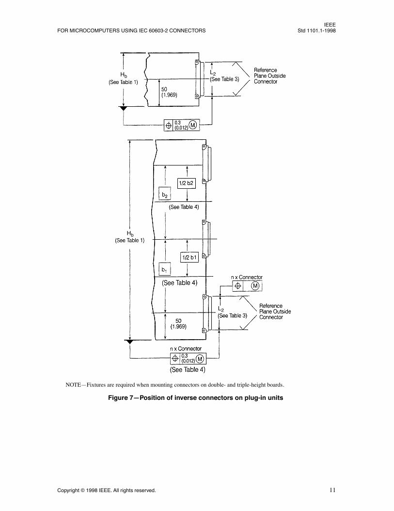
Figure 7ÑPosition of inverse connectors on plug-in units
NOTEÑFixtures are required when mounting connectors on double- and triple-height boards.
Hb
Hb
L2
L2

IEEEStd 1101.1-1998 IEEE STANDARD FOR MECHANICAL CORE SPECIFICATIONS
12
Copyright © 1998 IEEE. All rights reserved.
8. Plug-in unit description
A plug-in unit can be of various types, as is shown in Figure 1. It usually consists of a printed board assem-bly with connector(s) and, optionally, handle(s), ejector(s), front panel, rear panel, mounting rails, and cov-ers.
A plug-in unit can itself house a plurality of different types of plug-in units. Box-type plug-in units mayhouse board-type plug-in units or other subassemblies.
9. Plug-in unit dimensions
9.1 Board-type plug-in units
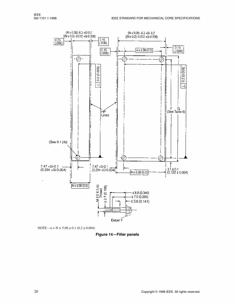
1) DT2 in Table 5 is the inspection dimension to ensure reliable connector mating.2) For connector detail, see IEC 60603-2 (1995-09).3) For a nominal 5.08 mm (0.2 in) width Þller panel (see Figure 14), the 7.47 mm (0.294 in) dimension
is reduced to 2.35 mm (0.093 in).4) Maximum dimensions for location features for front panel alignment or screw retention, or both, are
shown in Figures 13 and 14. The standard M2.5 screw mounting does not exclude other means ofretention or quick-release fasteners (to be agreed upon by vendor and user). Slotted or plus-typescrew heads are permitted.
5) Double-sided surface-mounted devices (SMD) mounting on plug-in boards may result in changes ofthe relationship of front panel, guide rail, and backplane positioning relative to the subrack (see Fig-ure 15).
6) The injector/ejector design detail can be derived from Figures 8 and 9, and can be manufactured ofvarious materials (see 12.6.2). This detail is restricted to individual boards plugged into the subrack,and is not suitable for front panel mounted boards or within a box-type plug-in unit (see Figure 19).
7) The dimension between the front attachment plane and the beginning of the board guide has beenincreased from
³
6 mm (0.236 in) as per IEC 60297-3 (1984-01) to
³
10 mm (0.393 in) as per IEC60297-4 (see Figures 28 through 33) in order to allow for injector/ejector operation.
8) Board-type plug-in units with front panels may require handles. The details of handles and theirpositioning on the front panels are not speciÞed in this standard.
9) The recommended plug-in unit front panel thickness is 2.5 mm (0.098 in).
9.2 Box-type, box/board-type plug-in units
1) DT2 is the inspection dimension to ensure reliable connector mating. For inspection dimensions, seeTable 5.
2) For connector details, see IEC 60603-2 (1995-09).3) Box-type plug-in units are designed to interface with the subrack, as speciÞed in Clause 11, via a
single board, as speciÞed in Figures 3 through 5, with connectors attached. Additionally, the box-type plug-in units may be used to house large components.
4) Box/board-type plug-in units are designed to interface with the subrack, as speciÞed in Clause 11,via one or more board-type plug-in unit(s), as speciÞed in Figures 3 through 5 and 10 through 12,with connector(s) attached [see IEC 60603-2 (1995-09)]. Individual front panels can be replaced bysingle plug-in unit front panels, or in other combinations of N
´
5.08 mm (0.2 in).5) Box and box/board-type plug-in units may require handles [see 9.1, item 8)].

IEEEFOR MICROCOMPUTERS USING IEC 60603-2 CONNECTORS Std 1101.1-1998
Copyright © 1998 IEEE. All rights reserved.
13
10. Backplane design and mounting positions
10.1 Rigidity
Backplane and subrack mounting positions must be sufÞciently rigid to withstand the insertion and with-drawal forces of the connectors, as per IEC 60603-2 (1995-09).
10.2 Dimensions
The dimension 7.47 mm (0.294 in) is the minimum dimension to the Þrst mounting hole. This dimension canbe increased by increments of N
´
5.08 mm (0.2 in).
NOTEÑFor backplane, connector, board, and front panel relationships, see Figure 15.
Table 5ÑInspection dimensions, Figures 10Ð12
Reference Board Depth
D
b
100 160 220 280 340 400
DT2 ± 0.4 mm(±0.016 in)
109.93 mm(4.328 in)
169.93 mm(6.690 in)
229.93 mm(9.052 in)
289.93 mm(11.415 in)
349.93 mm(13.777 in)
409.93 mm(16.139 in)
Table 6ÑFront panel dimensions, Figures 13, 14, 17, 19, 20Ð23;Backplane dimensions, Figures 24Ð26
Reference Subrack Heights U 3 6 9
G+0/Ð0.3 mm (+0/Ð012 in) 128.7 mm (5.067 in) 262.05 mm (10.317 in) 395.40 mm (15.567 in)
F
1
± 0.2 mm (±0.008 in) 122.5 mm (4.823 in) Ñ Ñ
F
2
± 0.2 mm (±0.008 in) Ñ 255.85 mm (10.073 in) Ñ
F
3
± 0.2 mm (±0.008 in) Ñ Ñ 389.20 mm (15.323 in)
IEEEStd 1101.1-1998 IEEE STANDARD FOR MECHANICAL CORE SPECIFICATIONS
14
Copyright © 1998 IEEE. All rights reserved.
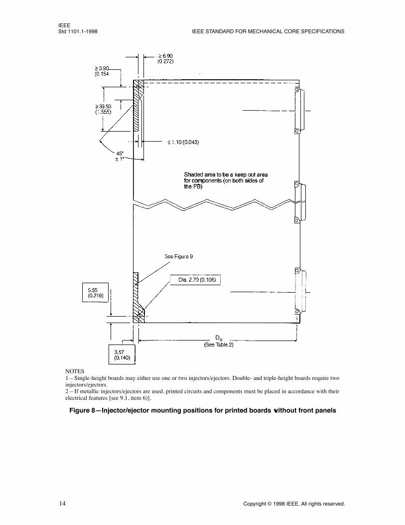
Figure 8ÑInjector/ejector mounting positions for printed boards without front panels
NOTES 1ÑSingle-height boards may either use one or two injectors/ejectors. Double- and triple-height boards require twoinjectors/ejectors.2ÑIf metallic injectors/ejectors are used, printed circuits and components must be placed in accordance with theirelectrical features [see 9.1, item 6)].
Da

IEEEFOR MICROCOMPUTERS USING IEC 60603-2 CONNECTORS Std 1101.1-1998
Copyright © 1998 IEEE. All rights reserved.
15
NOTEÑTo be an optional and removable part, if in compliance with IEC 60297-3 (1984-01). The injection plane canbe of full width design if agreed between vendor and user [see 9.1, items 6) and 7)].
Figure 9ÑInjector/ejector detail for use of printed boards without attached front panels

IEEEStd 1101.1-1998 IEEE STANDARD FOR MECHANICAL CORE SPECIFICATIONS
16
Copyright © 1998 IEEE. All rights reserved.
NOTEÑFor front panel handles, see 9.1, item 8).
Figure 10ÑSingle-height board-type plug-in unit
Component Side 1
< Hs

IEEEFOR MICROCOMPUTERS USING IEC 60603-2 CONNECTORS Std 1101.1-1998
Copyright © 1998 IEEE. All rights reserved.
17
NOTEÑFor front panel handles, see 9.1, item 8).
Figure 11ÑDouble-height board-type plug-in unit
Component Side 1
< Hs

IEEEStd 1101.1-1998 IEEE STANDARD FOR MECHANICAL CORE SPECIFICATIONS
18
Copyright © 1998 IEEE. All rights reserved.
NOTEÑBoard stiffeners are recommended. For front panel handles, see 9.1, item 8).
Figure 12ÑTriple-height board-type plug-in unit
Component Side 1
< Hs
F3

IEEEFOR MICROCOMPUTERS USING IEC 60603-2 CONNECTORS Std 1101.1-1998
Copyright © 1998 IEEE. All rights reserved.
19
NOTEÑn = N ´ 5.08 ± 0.1 (0.2 ± 0.004)
Figure 13ÑBoard-type plug-in unit front panel
IEEEStd 1101.1-1998 IEEE STANDARD FOR MECHANICAL CORE SPECIFICATIONS
20
Copyright © 1998 IEEE. All rights reserved.
NOTEÑn = N ´ 5.08 ± 0.1 (0.2 ± 0.004)
Figure 14ÑFiller panels

IEEEFOR MICROCOMPUTERS USING IEC 60603-2 CONNECTORS Std 1101.1-1998
Copyright © 1998 IEEE. All rights reserved.
21
Figure 15ÑFront panel, board, connector, backplane relationship
NOTEÑThe dimension 4.07 mm (0.160 in) represents the Þrst board position for conventional component mounting(on component side 1). For double-sided surface-mounted devices (SMD) boards (component side 1 and 2) thedimension of 4.07 mm (0.160 in) may be increased to 9.15 mm (0.360 in) = 4.07 + 5.08 (0.160 + 0.200). For boardthickness, see 6.3. Thicker boards shall grow towards the component side 2 and may have to be routed in the guidearea.
IEEEStd 1101.1-1998 IEEE STANDARD FOR MECHANICAL CORE SPECIFICATIONS
22 Copyright © 1998 IEEE. All rights reserved.
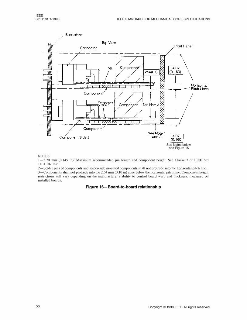
NOTES1Ñ3.70 mm (0.145 in): Maximum recommended pin length and component height. See Clause 7 of IEEE Std1101.10-1996.2ÑSolder pins of components and solder-side mounted components shall not protrude into the horizontal pitch line.3ÑComponents shall not protrude into the 2.54 mm (0.10 in) zone below the horizontal pitch line. Component heightrestrictions will vary depending on the manufacturerÕs ability to control board warp and thickness, measured oninstalled boards.
Figure 16ÑBoard-to-board relationship
See Notes below and Figure 15

IEEEFOR MICROCOMPUTERS USING IEC 60603-2 CONNECTORS Std 1101.1-1998
Copyright © 1998 IEEE. All rights reserved. 23
NOTES1ÑSee 6.4 and 9.2, items 3) and 5).2Ñn = N ´ 5.08 ± 0.1 (0.2 ± 0.004)
Figure 17ÑBox-type plug-in unit, front view
Hb< Hs

IEEEStd 1101.1-1998 IEEE STANDARD FOR MECHANICAL CORE SPECIFICATIONS
24 Copyright © 1998 IEEE. All rights reserved.
Figure 18ÑBox-type plug-in unit, plan view section A-A

IEEEFOR MICROCOMPUTERS USING IEC 60603-2 CONNECTORS Std 1101.1-1998
Copyright © 1998 IEEE. All rights reserved. 25
Figure 19ÑBox/board-type plug-in, front view
NOTES1ÑInternal guides have the same board slot feature as shown in Figure 28, item X. See 6.4 and 9.2, items 4) and 5).2Ñn = N ´ 5.08 ± 0.1 (0.2 ± 0.004)
Hb < Hs
IEEEStd 1101.1-1998 IEEE STANDARD FOR MECHANICAL CORE SPECIFICATIONS
26 Copyright © 1998 IEEE. All rights reserved.
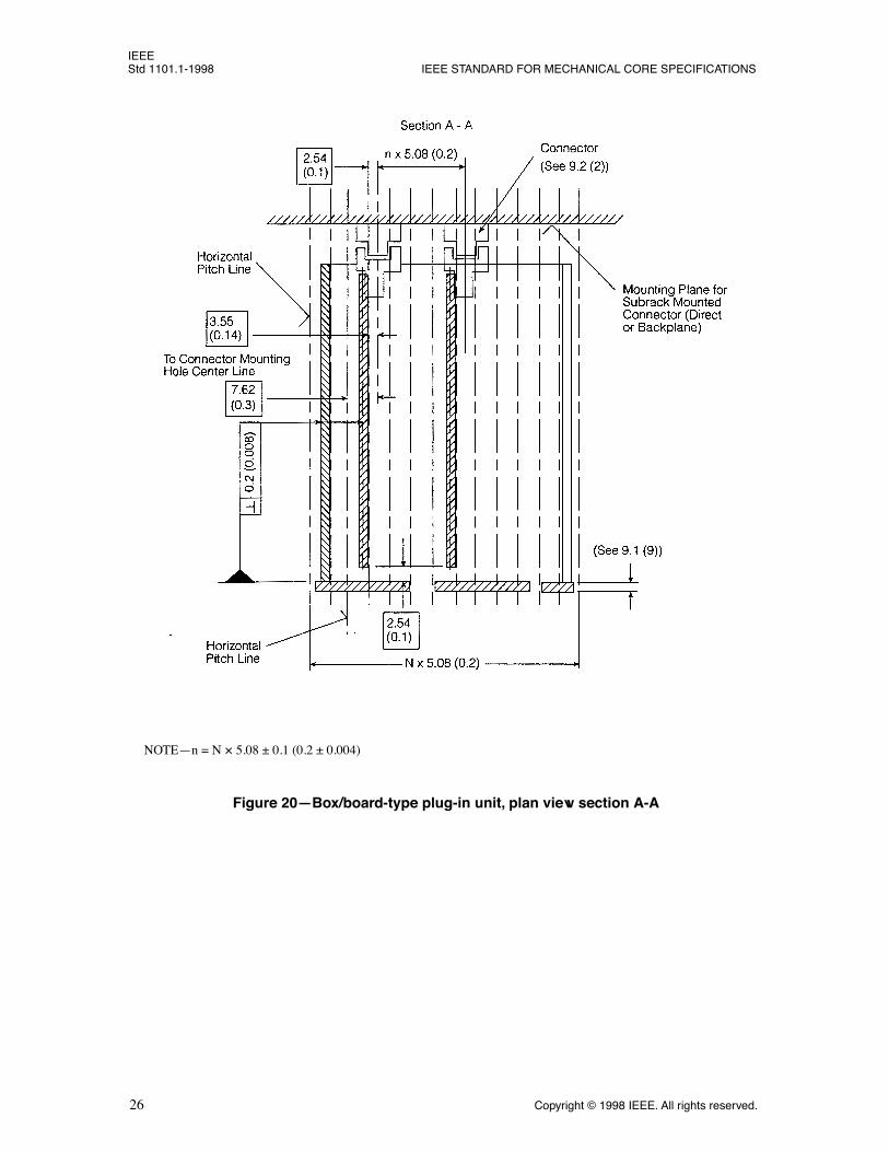
Figure 20ÑBox/board-type plug-in unit, plan view section A-A
NOTEÑn = N ´ 5.08 ± 0.1 (0.2 ± 0.004)

IEEEFOR MICROCOMPUTERS USING IEC 60603-2 CONNECTORS Std 1101.1-1998
Copyright © 1998 IEEE. All rights reserved. 27
NOTEÑSee 9.2, item 5).
Figure 21ÑBox-type, box/board-type plug-in unit, single-height side view
Hb
F1
£ Db + 10 (0.394)
L1/L2

IEEEStd 1101.1-1998 IEEE STANDARD FOR MECHANICAL CORE SPECIFICATIONS
28 Copyright © 1998 IEEE. All rights reserved.
NOTEÑSee 9.2, item 5).
Figure 22ÑBox-type, box/board-type plug-in unit, double-height side view
Hb
£ Db + 10 (0.394)
F2
L1/L2
L1/L2

IEEEFOR MICROCOMPUTERS USING IEC 60603-2 CONNECTORS Std 1101.1-1998
Copyright © 1998 IEEE. All rights reserved. 29
Figure 23ÑBox-type, box/board-type plug-in unit, triple-height side view
NOTEÑSee 9.2, item 5).
£ Db + 10 (0.394)
Hb
L1/L2
L1/L2
L1/L2

IEEEStd 1101.1-1998 IEEE STANDARD FOR MECHANICAL CORE SPECIFICATIONS
30 Copyright © 1998 IEEE. All rights reserved.
NOTES 1Ñn = N ´ 5.08 ± 0.1 (0.2 ± 0.004)2ÑThe distance between the subrack mounting holes has to be chosen to give adequate support to the backplane.3ÑThe dimension 7.47 mm (0.294 in) indicates the Þrst speciÞed mounting position of the backplane to the subrackand the connector to the backplane. Other dimensions are also possible and may be deÞned by other relevant stan-dards or are to be agreed upon by vendor and user.
Figure 24ÑSingle-height backplane

IEEEFOR MICROCOMPUTERS USING IEC 60603-2 CONNECTORS Std 1101.1-1998
Copyright © 1998 IEEE. All rights reserved. 31
NOTES1Ñn = N ´ 5.08 ± 0.1 (0.2 ± 0.004)2ÑThe distance between the subrack mounting holes has to be chosen to give adequate support to the backplane.3ÑThe dimension 7.47 mm (0.294 in) indicates the Þrst speciÞed mounting position of the backplane to the subrackand the connector to the backplane. Other dimensions are also possible and may be deÞned by other relevant stan-dards or are to be agreed upon by vendor and user.
Figure 25ÑDouble-height backplane
F1
F1

IEEEStd 1101.1-1998 IEEE STANDARD FOR MECHANICAL CORE SPECIFICATIONS
32 Copyright © 1998 IEEE. All rights reserved.
Figure 26ÑTriple-height backplane
NOTES 1Ñn = N ´ 5.08 ± 0.1 (0.2 ± 0.004)2ÑThe distance between the subrack mounting holes has to be chosen to give adequate support to the backplane.3ÑThe dimension 7.47 mm (0.294 in) indicates the Þrst speciÞed mounting position of the backplane to the sub-rack and the connector to the backplane. Other dimensions are also possible and may be deÞned by other relevantstandards or are to be agreed upon by vendor and user.
F1
F1
F1

IEEEFOR MICROCOMPUTERS USING IEC 60603-2 CONNECTORS Std 1101.1-1998
Copyright © 1998 IEEE. All rights reserved. 33
NOTEÑFixtures are required when mounting connectors on double- and triple-height backplanes, and when back-planes are mounted to the subrack. For backplane ßatness/bow see Clause 11, item 8).
Figure 27ÑPosition of connectors on backplane
F1
F2
F3
b2
b2
b1
b1
L1 + L2
L1 + L2
IEEEStd 1101.1-1998 IEEE STANDARD FOR MECHANICAL CORE SPECIFICATIONS
34 Copyright © 1998 IEEE. All rights reserved.
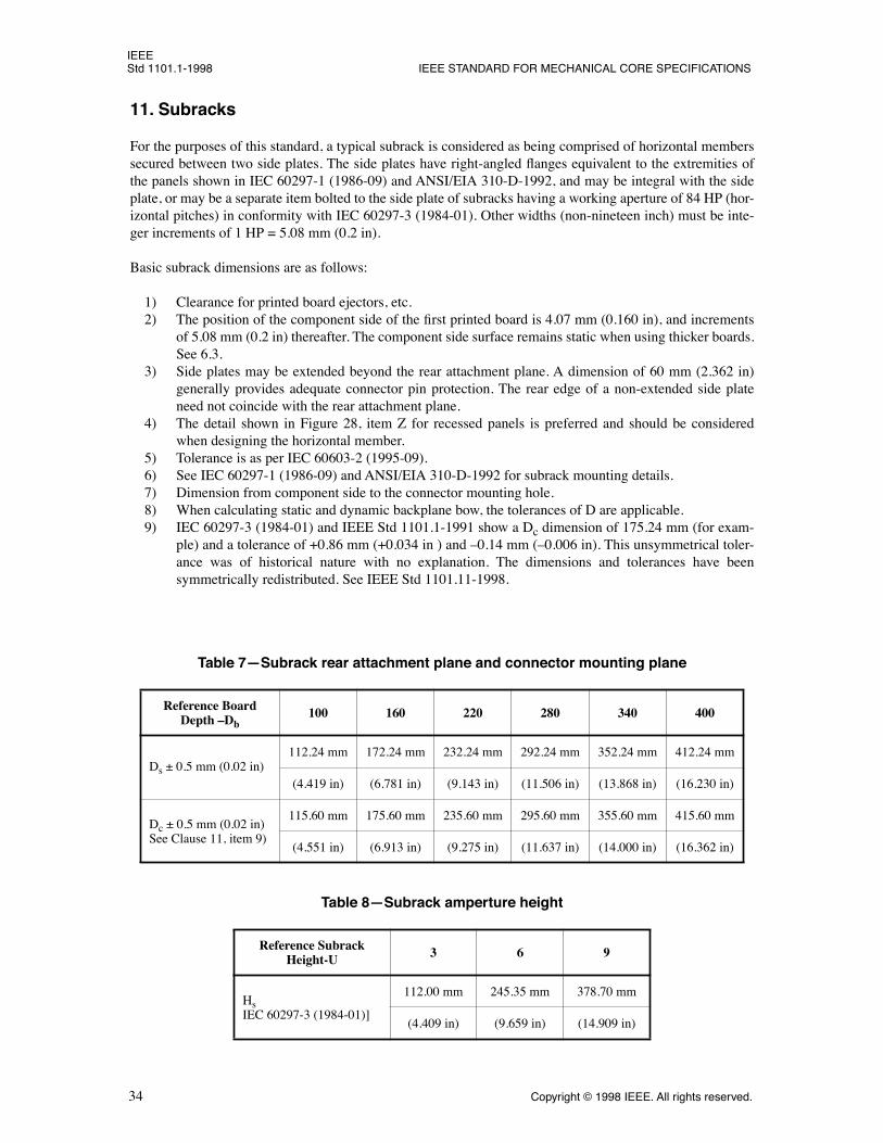
11. Subracks
For the purposes of this standard, a typical subrack is considered as being comprised of horizontal memberssecured between two side plates. The side plates have right-angled ßanges equivalent to the extremities ofthe panels shown in IEC 60297-1 (1986-09) and ANSI/EIA 310-D-1992, and may be integral with the sideplate, or may be a separate item bolted to the side plate of subracks having a working aperture of 84 HP (hor-izontal pitches) in conformity with IEC 60297-3 (1984-01). Other widths (non-nineteen inch) must be inte-ger increments of 1 HP = 5.08 mm (0.2 in).
Basic subrack dimensions are as follows:
1) Clearance for printed board ejectors, etc.2) The position of the component side of the Þrst printed board is 4.07 mm (0.160 in), and increments
of 5.08 mm (0.2 in) thereafter. The component side surface remains static when using thicker boards.See 6.3.
3) Side plates may be extended beyond the rear attachment plane. A dimension of 60 mm (2.362 in)generally provides adequate connector pin protection. The rear edge of a non-extended side plateneed not coincide with the rear attachment plane.
4) The detail shown in Figure 28, item Z for recessed panels is preferred and should be consideredwhen designing the horizontal member.
5) Tolerance is as per IEC 60603-2 (1995-09).6) See IEC 60297-1 (1986-09) and ANSI/EIA 310-D-1992 for subrack mounting details.7) Dimension from component side to the connector mounting hole.8) When calculating static and dynamic backplane bow, the tolerances of D are applicable.9) IEC 60297-3 (1984-01) and IEEE Std 1101.1-1991 show a Dc dimension of 175.24 mm (for exam-
ple) and a tolerance of +0.86 mm (+0.034 in ) and Ð0.14 mm (Ð0.006 in). This unsymmetrical toler-ance was of historical nature with no explanation. The dimensions and tolerances have beensymmetrically redistributed. See IEEE Std 1101.11-1998.
Table 7ÑSubrack rear attachment plane and connector mounting plane
Reference Board Depth ÐDb
100 160 220 280 340 400
Ds ± 0.5 mm (0.02 in)112.24 mm 172.24 mm 232.24 mm 292.24 mm 352.24 mm 412.24 mm
(4.419 in) (6.781 in) (9.143 in) (11.506 in) (13.868 in) (16.230 in)
Dc ± 0.5 mm (0.02 in)See Clause 11, item 9)
115.60 mm 175.60 mm 235.60 mm 295.60 mm 355.60 mm 415.60 mm
(4.551 in) (6.913 in) (9.275 in) (11.637 in) (14.000 in) (16.362 in)
Table 8ÑSubrack amperture height
Reference Subrack Height-U 3 6 9
HsIEC 60297-3 (1984-01)]
112.00 mm 245.35 mm 378.70 mm
(4.409 in) (9.659 in) (14.909 in)
IEEEFOR MICROCOMPUTERS USING IEC 60603-2 CONNECTORS Std 1101.1-1998
Copyright © 1998 IEEE. All rights reserved. 35
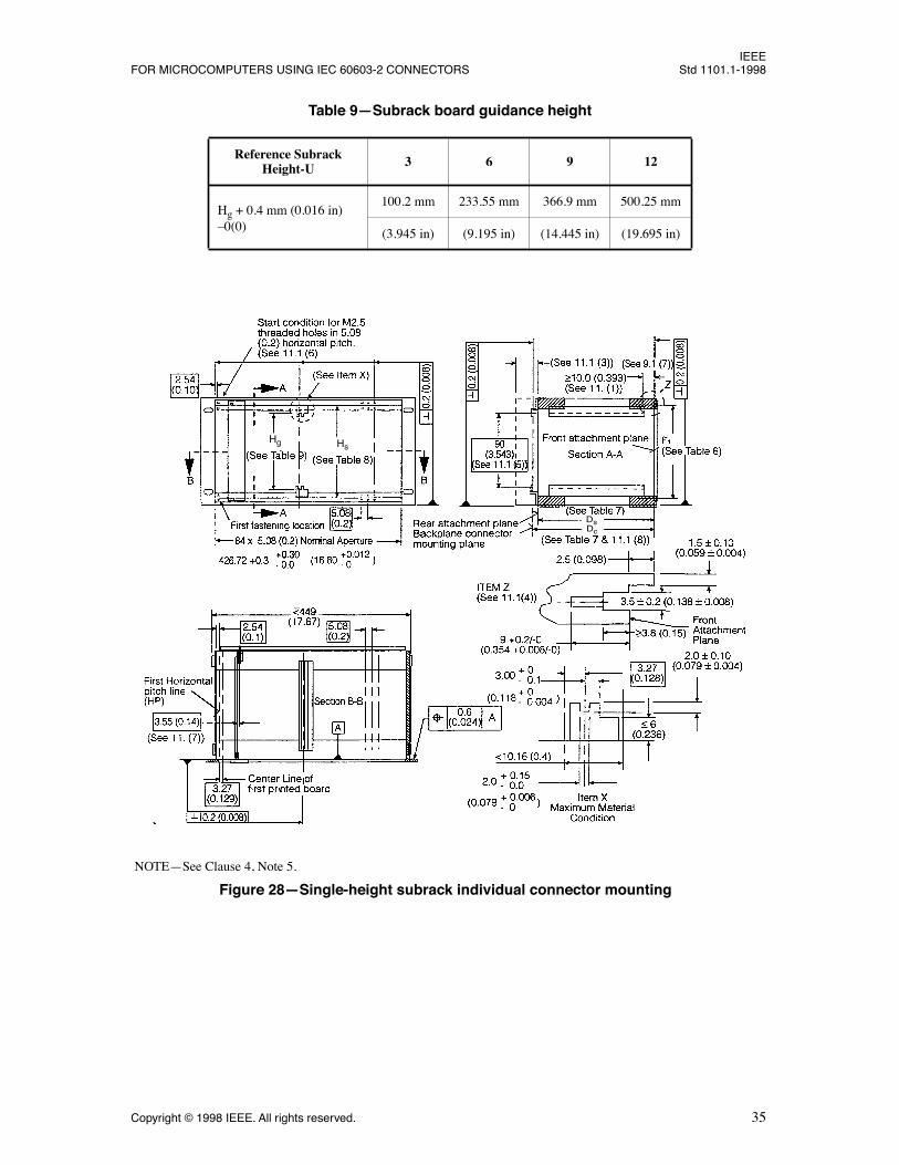
Table 9ÑSubrack board guidance height
Reference Subrack Height-U 3 6 9 12
Hg + 0.4 mm (0.016 in)Ð0(0)
100.2 mm 233.55 mm 366.9 mm 500.25 mm
(3.945 in) (9.195 in) (14.445 in) (19.695 in)
NOTEÑSee Clause 4, Note 5.
Figure 28ÑSingle-height subrack individual connector mounting
Hg Hs
DsDc

IEEEStd 1101.1-1998 IEEE STANDARD FOR MECHANICAL CORE SPECIFICATIONS
36 Copyright © 1998 IEEE. All rights reserved.
NOTEÑSee Clause 4, Note 5.
Figure 29ÑSingle-height subrack individual connector mounting
Hg Hs
DsDc
IEEEFOR MICROCOMPUTERS USING IEC 60603-2 CONNECTORS Std 1101.1-1998
Copyright © 1998 IEEE. All rights reserved. 37
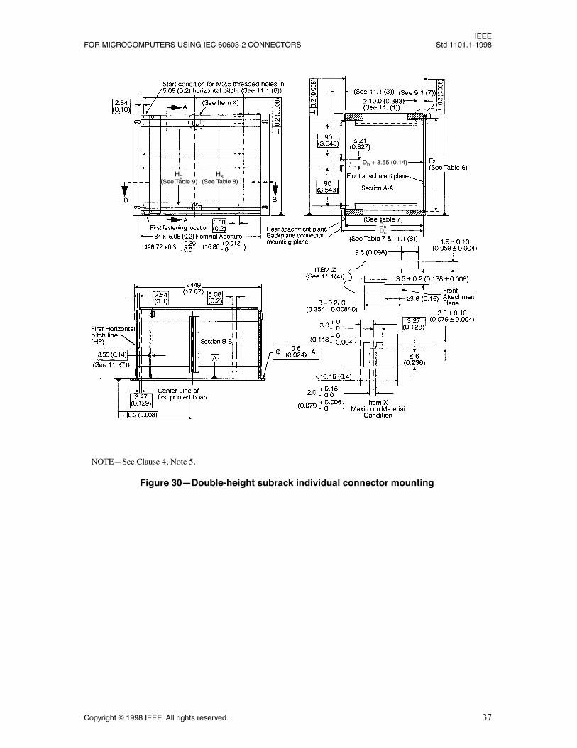
NOTEÑSee Clause 4, Note 5.
Figure 30ÑDouble-height subrack individual connector mounting
Hs (See Table 8)(See Table 9)
Hg
DsDc
Db + 3.55 (0.14)

IEEEStd 1101.1-1998 IEEE STANDARD FOR MECHANICAL CORE SPECIFICATIONS
38 Copyright © 1998 IEEE. All rights reserved.
NOTEÑSee Clause 4, Note 5.
Figure 31ÑDouble-height subrack backplane mounting
DsDc
Hg (See Table 9) (See Table 8)
Hs
Db + 3.55 (0.14)

IEEEFOR MICROCOMPUTERS USING IEC 60603-2 CONNECTORS Std 1101.1-1998
Copyright © 1998 IEEE. All rights reserved. 39
NOTEÑSee Clause 4, Note 5.
Figure 32ÑTriple-height subrack individual connector mounting
DsDc
(See Table 8)Hs Hg
(See Table 9)
Db + 3.55 (0.14)

IEEEStd 1101.1-1998 IEEE STANDARD FOR MECHANICAL CORE SPECIFICATIONS
40 Copyright © 1998 IEEE. All rights reserved.
NOTEÑSee Clause 4, Note 5.
Figure 33ÑTriple-height subrack backplane mounting
DsDc
(See Table 8)Hs Hg
(See Table 9)
Db + 3.55 (0.14)
IEEEFOR MICROCOMPUTERS USING IEC 60603-2 CONNECTORS Std 1101.1-1998
Copyright © 1998 IEEE. All rights reserved. 41
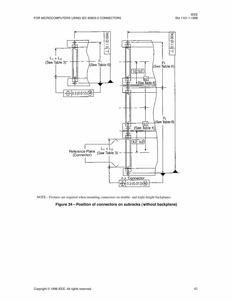
NOTEÑFixtures are required when mounting connectors on double- and triple-height backplanes.
Figure 34ÑPosition of connectors on subracks (without backplane)
L1 + L2
L1 + L2
IEEEStd 1101.1-1998 IEEE STANDARD FOR MECHANICAL CORE SPECIFICATIONS
42 Copyright © 1998 IEEE. All rights reserved.
12. Environmental speciÞcations
12.1 Introduction
It is the purpose of this standard to ensure a minimum level of physical integrity and environmental perfor-mance in mechanical subracks, plug-in units, and backplanes, while taking into account the need for differ-ent levels of performance in different applications.
To provide a consistent and repeatable method for ensuring a minimum level of integrity and environmentalperformance during storage, handling, and transport, this clause details a standard test sequence that all sub-racks, plug-in units, and backplanes speciÞed in this standard shall be capable of passing.
In order to provide maximum compatibility with existing IEC standards, this standard refers to the IEC60068, Environmental Testing Procedures series of documents. Where differences exist between this stan-dard and the IEC 60068 publications, this standard shall take precedence.
It is the system designerÕs responsibility to evaluate the correspondence between the systemÕs plug-in unitsand subracks, and the systemÕs environment.
12.2 Climatic tests
These tests are to be undertaken under non-operating conditions.
12.2.1 Steady cold
This test is in accordance with IEC 60068-2-1 (1990-05); Ð40 ¡C for 72 hours.
12.2.2 Steady dry heat
This test is in accordance with IEC 60068-2-2 (1974-01); +70 ¡C for 96 hours.
12.2.3 Cyclic damp heat
This test should be run varying from +25 ¡C to +40 ¡C at 95% relative humidity for 21 days.
12.2.4 Salt mist
This test is in accordance with IEC 60068-2-11 (1981-01); 5% for 96 hours (crevice corrosion testing).
12.3 Mechanical load
Test condition.
12.3.1 Load per 1 HP (84 HP available)
See Table 10.
NOTEÑFiller panels and plug-in unit front panels shall be bolted onto the subrack.
IEEEFOR MICROCOMPUTERS USING IEC 60603-2 CONNECTORS Std 1101.1-1998
Copyright © 1998 IEEE. All rights reserved. 43
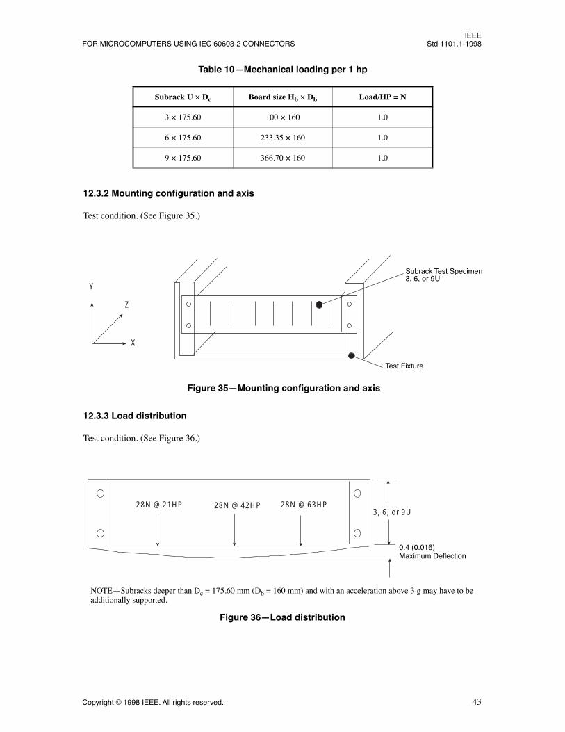
12.3.2 Mounting conÞguration and axis
Test condition. (See Figure 35.)
12.3.3 Load distribution
Test condition. (See Figure 36.)
Table 10ÑMechanical loading per 1 hp
Subrack U ´ Dc Board size Hb ´ Db Load/HP = N
3 ´ 175.60 100 ´ 160 1.0
6 ´ 175.60 233.35 ´ 160 1.0
9 ´ 175.60 366.70 ´ 160 1.0
Test Fixture
Subrack Test Speci3, 6, or 9U
Y
Z
X
Figure 35ÑMounting conÞguration and axis
Subrack Test Specimen3, 6, or 9U
Test Fixture
28N @ 21HP 28N @ 42HP 28N @ 63HP3, 6, or 9U
0.4 (0.016)Maximum Deflection
Figure 36ÑLoad distribution
NOTEÑSubracks deeper than Dc = 175.60 mm (Db = 160 mm) and with an acceleration above 3 g may have to beadditionally supported.
0.4 (0.016)Maximum Deflection

IEEEStd 1101.1-1998 IEEE STANDARD FOR MECHANICAL CORE SPECIFICATIONS
44 Copyright © 1998 IEEE. All rights reserved.
12.4 Vibration
1) Tests for sinusoidal vibration are per IEC 60068-2-6 (1995-03).2) Initial resonance search: X, Y, and Z directions.3) Endurance condition by sweeping: 10-55 Hz, 0.15 mm, 2 9.8 m/s2 as a minimum, for sweeps 17.9
m/s2 is suitable for applications such as placement next to rotating machineries, etc.4) Endurance condition at resonance frequency: 10 min each direction.
12.5 Shock
Tests of shock is as per IEC 60068-2-27 (1987-06), 100 m/s2 at 11 ms at 3 ´ 1000 shocks.
12.6 Safety tests
12.6.1 Earth resistance
See IEC 61010-1 (1990-09). There must be electrical continuity between all metallic elements of the sub-rack. The resistance of the connection between the protective earthing terminal or earthing contact and partsrequired to be earthed shall be less than 0.1 W. Front panels of subracks and plug-in units may optionally becontinuous with the subrack, depending on application.
12.6.2 Flammability of plastic materials
See IEC 60707 (1981-01). Materials shall have a ßammability classiÞcation of FV2 or better. [See Test 9 ofIEC 60707 (1981-01).]
12.6.3 Transport recommendation
Transport test parameters for a subrack mounted in a 19 in cabinet [tests based on IEC 60068-2-27 (1987-06)] are shown in Table 11.
12.6.4 Mass >30 kg
In practice, transport occurs mostly in systems with a total mass of >30 kg. As lower mechanical forces atthis mass can be expected, less stringent tests are required (10Ð55 Hz, 0.15 mm).
12.6.5 Mass <30 kg
For objects with a mass of <30 kg, when mounted in a standard 19 in cabinet, additional supports arerequired. Mechanical vibration tests (50 m/s2, 0.35 mm) have to be carried out.
Table 11ÑTransport test parameters
Test Mass Frequency Maximum Amplitude
Maximum Acceleration
Transport 30 kg 10Ð150 Hz 0.35 mm 50 m/s2
Transport 30Ð100 kg 10Ð55 Hz 0.15 mm 17.9 m/s2

IEEEFOR MICROCOMPUTERS USING IEC 60603-2 CONNECTORS Std 1101.1-1998
Copyright © 1998 IEEE. All rights reserved. 45
12.6.6 Electromagnetic interference/radio-frequency interference (EMI/RFI)
Subracks as speciÞed in this standard are of open construction, and by their nature offer no protectionagainst incoming and transmitting interferences. Plug-in unit metal front panels and metal Þller panels offeronly limited protection when the subrack is mounted in a case or cabinet without a door. Three places thatthe systemÕs designer can provide features that will reduce RFI emissions to allow the system to meet stan-dard requirements (such as those speciÞed in CFR Title 47, Part 15J) are the circuit board, the subrack, andthe system enclosure.
RFI reduction techniques are usually a combination of grounding and shielding. The system designer mustprovide sufÞcient reduction to pass inspection, but must also stay within a cost budget. In order to intelli-gently apply the techniques at his or her disposal, the system designer needs to know the sources of radia-tion, its magnitude, and speciÞc frequencies involved.
Ñ Recommendation 1: The subrack should be made of metal so that the chassis ground is conveyed toall frame components.
Ñ Recommendation 2: Clarify board speciÞcations to allow and designate areas on the board outlinethat would provide connection to the chassis on three edges of the board. A board that has groundingonly on one edge can act as a quarter-wave antenna when it is radiating. A board that is grounded attwo opposite edges would radiate as a half-wave antenna, tuned to twice the frequency of the quarterwave mode. The mounting pads that attach the front panels can be used as grounding points. Theedges of the board that go into the board guide could be used as additional grounding points. The cir-cuit board manufacturer may either directly connect logic ground to chassis ground, or may connectit through a capacitor, which would allow a dc potential between ground and logic ground.
Ñ Recommendation 3: The FCC or UL only requires certiÞcation of systems, not individual boards orcomponents of the system. However, if board manufacturers publish the radiation characteristics oftheir boards, then the system designer would know the total sum of the individual components and areasonable estimate of the required RFI reduction could be made.
Ñ Recommendation 4: For subracks without bus bars for power and potential distribution it is recom-mended to distribute the potential in ÒstarÓ routing to the supply source or the dedicated potentialposition of the case or cabinet in which the subrack is housed. All metallic parts of the mechanical/metal system should be electrically continuous. Connector cross sections must be of adequate thick-ness. Conductor cross sections should only be reduced from the source in the direction of the con-sumer.
12.6.7 Cooling
Subracks and plug-in units should be constructed in such a manner that obstructions to the airßow areavoided where possible.
High-density packaging does not necessarily save space or cost, as space consuming and costly forced cool-ing/ventilation systems are often required, and may consist of the following:
1) Natural convection2) Forced air circulation3) Forced fresh air intake/circulation4) Heat exchangers suitable for sealed cabinets5) Air conditioners suitable for sealed cabinets

IEEEStd 1101.1-1998 IEEE STANDARD FOR MECHANICAL CORE SPECIFICATIONS
46 Copyright © 1998 IEEE. All rights reserved.
The appropriate cooling method has to be chosen and calculated pending system construction, system appli-cation, and ambient air temperature.
The following typical noise levels are given as examples of various environments, and should be used as aguide when designing-in air moving equipment:
55 dB (A)ÑConcentration environment70 dB (A)ÑOfÞce environment85 dB (A)ÑIndustrial working environment
Blowers transmit a mix of frequencies, and these individual frequencies show different amplitudes. [See IEC60651 (1979-01)].
IEEEFOR MICROCOMPUTERS USING IEC 60603-2 CONNECTORS Std 1101.1-1998
Copyright © 1998 IEEE. All rights reserved. 47
Annex A
(informative)
Bibliography
[B1] IEC 60050, International Electrotechnical Vocabulary.
[B2] IEC 60917-1 (1998-09), Modular order for the development if mechanical structures for electronicequipment practicesÑPart 1: Generic standard.
[B3] ISO 1101:1983, Technical drawingsÑGeometric tolerancingÑTolerancing of form, orientation, loca-tion and run-outÑGeneralities, deÞnitions, symbols, indications on drawings.6
6ISO publications are available from the ISO Central Secretariat, Case Postale 56, 1 rue de Varemb�, CH-1211, Gen�ve 20, Switzer-land/Suisse. ISO publications are also available in the United States from the Sales Department, American National Standards Institute,11 West 42nd Street, 13th Floor, New York, NY 10036, USA.