IEEE Standard for Software Maintenance · IEEE Std 1219-1992 IEEE STANDARD FOR 2 IEEE Std...
45
The Institute of Electrical and Electronics Engineers, Inc. 345 East 47th Street, New York, NY 10017-2394, USA Copyright 1993 by the Institute of Electrical and Electronics Engineers, Inc. All rights reserved. Published 1993. Printed in the United States of America ISBN 1-55937-279-6 No part of this publication may be reproduced in any form, in an electronic retrieval system or otherwise, without the prior written permission of the publisher. IEEE Std 1219-1993 IEEE Standard for Software Maintenance Sponsor Software Engineering Standards Subcommittee of the IEEE Computer Society Approved December 3, 1992 IEEE Standards Board Abstract: The process for managing and executing software maintenance activities is described. Keywords: maintenance, software, software maintenance
Transcript of IEEE Standard for Software Maintenance · IEEE Std 1219-1992 IEEE STANDARD FOR 2 IEEE Std...
The Institute of Electrical and Electronics Engineers, Inc.345 East 47th Street, New York, NY 10017-2394, USA
Copyright
Ó
1993 by the Institute of Electrical and Electronics Engineers, Inc.All rights reserved. Published 1993. Printed in the United States of America
ISBN 1-55937-279-6
No part of this publication may be reproduced in any form, in an electronic retrieval system or otherwise, without the prior written permission of the publisher.
IEEE Std 1219-1993
IEEE Standard for Software Maintenance
Sponsor
Software Engineering Standards Subcommittee
of the
IEEE Computer Society
Approved December 3, 1992
IEEE Standards Board
Abstract:
The process for managing and executing software maintenance activities is described.
Keywords:
maintenance, software, software maintenance
IEEE Standards
documents are developed within the Technical Committees of theIEEE Societies and the Standards Coordinating Committees of the IEEE StandardsBoard. Members of the committees serve voluntarily and without compensation.They are not necessarily members of the Institute. The standards developed withinIEEE represent a consensus of the broad expertise on the subject within the Instituteas well as those activities outside of IEEE that have expressed an interest in partici-pating in the development of the standard.
Use of an IEEE Standard is wholly voluntary. The existence of an IEEE Standarddoes not imply that there are no other ways to produce, test, measure, purchase, mar-ket, or provide other goods and services related to the scope of the IEEE Standard.Furthermore, the viewpoint expressed at the time a standard is approved and issued issubject to change brought about through developments in the state of the art andcomments received from users of the standard. Every IEEE Standard is subjected toreview at least every Þve years for revision or reafÞrmation. When a document ismore than Þve years old and has not been reafÞrmed, it is reasonable to conclude thatits contents, although still of some value, do not wholly reßect the present state of theart. Users are cautioned to check to determine that they have the latest edition of anyIEEE Standard.
Comments for revision of IEEE Standards are welcome from any interested party,regardless of membership afÞliation with IEEE. Suggestions for changes in docu-ments should be in the form of a proposed change of text, together with appropriatesupporting comments.
Interpretations: Occasionally questions may arise regarding the meaning of portionsof standards as they relate to speciÞc applications. When the need for interpretationsis brought to the attention of IEEE, the Institute will initiate action to prepare appro-priate responses. Since IEEE Standards represent a consensus of all concerned inter-ests, it is important to ensure that any interpretation has also received the concurrenceof a balance of interests. For this reason IEEE and the members of its technical com-mittees are not able to provide an instant response to interpretation requests except inthose cases where the matter has previously received formal consideration.
Comments on standards and requests for interpretations should be addressed to:
Secretary, IEEE Standards Board445 Hoes LaneP.O. Box 1331Piscataway, NJ 08855-1331USA
IEEE Standards documents are adopted by the Institute of Electrical and ElectronicsEngineers without regard to whether their adoption may involve patents on articles,materials, or processes. Such adoption does not assume any liability to any patentowner, nor does it assume any obligation whatever to parties adopting the standardsdocuments.
iii
Introduction
(This introduction is not a part of IEEE Std 1219-1992, IEEE Standard for Software Maintenance.)
This standard describes the process for managing and executing software maintenance activities. Clause 1lists references to other standards useful in applying this standard. Clause 2 provides a set of deÞnitions andacronyms that are either not found in other standards, or have been modiÞed for use with this standard.Clause 3 contains required information pertaining to the software maintenance process. In order to be incompliance with this standard, clause 3 must be adhered to.
Annex A, Maintenance guidelines, contains additional information that is not required for compliance. Top-ics in this annex include: the source of maintenance forms discussed in the standard, validation and veriÞca-tion (V&V), software quality assurance, risk assessment, safety, security, software conÞgurationmanagement (SCM), metrics, software replacement policy, and the maintenance process. Annex B, Support-ing maintenance technology, includes the topics re-engineering, reverse engineering, reuse, maintenanceplanning, impact analysis, and software tools.
The audience for which this standard is intended consists of software development managers, maintainers,software quality assurance personnel, SCM personnel, programmers, and researchers.
This standard was developed by a working group consisting of the following members who attended two ormore meetings, provided text, or submitted comments on more than two drafts of the standards.
D. Vera Edelstein,
Chair
Salvatore Mamone,
Secretary
Shawn A. Bohner Alan Huguley Ahlam ShalhoutRita Costello Moisey Lerner Malcolm SlovinRobert Dufresne Julio Gonzalez Sanz Edwin SummersFrank Douglas Ben Scheff Richard WeissGregory Haines Carl Seddio Ralph Wootton
The following individuals also contributed to the development of the standard by attending one meeting orproviding comments on one or two drafts.
Ray Abraham Meinhard Hoffman Yuan LiuJoseph Barrett T. S. Katsoulakos John LordJames E. Cardow Thomas Kurihura Kenneth MauerNeva Carlson Robert Leif Basil SherlundSharon Cobb Suzanne Leif Harry SneedSandra Falcone K. C. Leung Harry TrivediMari Georges Bob Walsh
iv
The following persons were on the balloting group that approved this document for submission to the IEEEStandards Board:
Ron Berlack Robert Kosinski Hans SchaeferWilliam Boll Thomas Kurihara David SchultzFletcher Buckley Robert Lane Gregory SchumacherKay Bydalek Boniface Lau D.M. SiefertEvelyn Dow Moisey Lerner Malcom SlovinEinar Dragstedt Ben Livson Al SorkowitzVera Edelstein Joseph Maayan Vijaya SrivastavaCaroline Evans Kukka Marijarvi Richard ThayerJohn Fendrich Roger Martin George TiceKirby Fortenberry Ivano Mazza Leonard TrippYar Gershkovitch James Perry Dolores WallaceDavid Gustafson Andrew Sage William WalshJohn Harauz Julio Gonzalez Sanz Robert WellsJohn Horch Stephen Schach Natalie YopconkaRoy Ko Janusz Zalewski
When the IEEE Standards Board approved this standard on December 3, 1992, it had the following member-ship:
Marco W. Migliaro,
Chair
Donald C. Loughry,
Vice Chair
Andrew G. Salem,
Secretary
Dennis Bodson Donald N. Heirman T. Don Michael*Paul L. Borrill Ben C. Johnson John L. RankineClyde Camp Walter J. Karplus Wallace S. ReadDonald C. Fleckenstein Ivor N. Knight Ronald H. ReimerJay Forster* Joseph KoepÞnger* Gary S. RobinsonDavid F. Franklin Irving Kolodny Martin V. SchneiderRamiro Garcia D. N. ÒJimÓ Logothetis Terrance R. WhittemoreThomas L. Hannan Lawrence V. McCall Donald W. Zipse
*Member Emeritus
Also included are the following nonvoting IEEE Standards Board liaisons:
Satish K. AggarwalJames Beall
Richard B. EngelmanDavid E. SoffrinStanley Warshaw
Christopher J. Booth
IEEE Standards Project Editor
v
Contents
CLAUSE PAGE
1. Overview.............................................................................................................................................. 1
1.1 Scope........................................................................................................................................ 11.2 References................................................................................................................................ 11.3 Terminology............................................................................................................................. 21.4 Conventions ............................................................................................................................. 3
2. Definitions and acronyms .................................................................................................................... 3
2.1 Definitions................................................................................................................................ 32.2 Acronyms................................................................................................................................. 4
3. Software maintenance.......................................................................................................................... 4
3.1 Problem/modification identification, classification, and prioritization ................................... 43.2 Analysis.................................................................................................................................... 83.3 Design .................................................................................................................................... 103.4 Implementation ...................................................................................................................... 113.5 System test ............................................................................................................................. 133.6 Acceptance test ...................................................................................................................... 143.7 Delivery.................................................................................................................................. 16
Annexes
Annex A
A.1 Definitions.................................................................................................................................... 19
A.2 References.................................................................................................................................... 20
A.3 Maintenance planning.................................................................................................................. 20
A.3.1 Determine maintenance effort.................................................................................... 20A.3.2 Determine current maintenance process .................................................................... 21A.3.3 Quantify maintenance effort ...................................................................................... 21A.3.4 Project maintenance requirements ............................................................................. 21A.3.5 Develop maintenance plan......................................................................................... 22
A.4 Maintenance process.................................................................................................................... 23
A.4.1 Problem/modification identification and classification ............................................. 23A.4.2 Analysis...................................................................................................................... 24A.4.3 Design ........................................................................................................................ 24A.4.4 Implementation .......................................................................................................... 25A.4.5 System test ................................................................................................................. 26A.4.6 Acceptance test .......................................................................................................... 26A.4.7 Delivery...................................................................................................................... 27
vi
CLAUSE PAGE
A.5 Maintenance forms....................................................................................................................... 27
A.6 Verification and validation (V&V).............................................................................................. 28
A.7 Software quality assurance .......................................................................................................... 28
A.8 Risk assessment ........................................................................................................................... 28
A.8.1 External exposure identification ................................................................................ 29A.8.2 Structural exposure analysis ...................................................................................... 29A.8.3 Software failure likelihood ........................................................................................ 29
A.9 Safety ........................................................................................................................................... 30
A.10 Security ........................................................................................................................................ 30
A.11 Software configuration management (SCM)............................................................................... 30
A.11.1 Problem/modification identification and classification ............................................. 31A.11.2 Analysis...................................................................................................................... 31A.11.3 Design ........................................................................................................................ 31A.11.4 Implementation .......................................................................................................... 31A.11.5 System testing ............................................................................................................ 32A.11.6 Acceptance testing ..................................................................................................... 32A.11.7 Delivery...................................................................................................................... 32
A.12 Metrics/measures ......................................................................................................................... 33
A.13 Software replacement policy........................................................................................................ 34
Annex B
B.1 Definitions.................................................................................................................................... 35
B.2 Re-engineering............................................................................................................................. 35
B.3 Reverse engineering..................................................................................................................... 36
B.4 Holistic reusing ............................................................................................................................ 36
B.5 Software tools .............................................................................................................................. 37
1
IEEE Standard for Software Maintenance
1. Overview
1.1 Scope
This standard describes an iterative process for managing and executing software maintenance activities.Use of this standard is not restricted by size, complexity, criticality, or application of the software product.This standard uses the process model, depicted in table 2, to discuss and depict each phase of software main-tenance. The criteria established apply to both the planning of maintenance for software while under devel-opment, as well as the planning and execution of software maintenance activities for existing softwareproducts. Ideally, maintenance planning should begin during the stage of planning for software development(see annex clause A.3 for guidance).
This standard prescribes requirements for process, control, and management of the planning, execution, anddocumentation of software maintenance activities. In totality, the requirements constitute a minimal set ofcriteria that are necessary and sufÞcient conditions for conformance to this standard. Users of this standardmay incorporate other items by reference or as text to meet their speciÞc needs.
The basic process model includes input, process, output, and control for software maintenance. Metrics/measures captured for maintenance should enable the manager to manage the process and the implementorto implement the process (see table 3). This standard does not presuppose the use of any particular develop-ment model (e.g., waterfall, spiral, etc.).
This standard provides additional software maintenance guidance on associated topics in annex A and tools/technology assistance in annex B.
1.2 References
The following standards are directly referenced in this standard. Table 1 provides a cross-reference of IEEEstandards that address various topics related to software maintenance. These standards are binding to theextent speciÞed within this standard and are referenced to avoid duplication of requirements.
IEEE Std 610.12-1990, IEEE Standard Glossary of Software Engineering Terminology (ANSI).
1
IEEE Std 730-1989, IEEE Standard for Software Quality Assurance Plans (ANSI).
IEEE Std 828-1990, IEEE Standard for Software ConÞguration Management Plans (ANSI).
IEEE Std 829-1983 (Reaff 1991), IEEE Standard for Software Test Documentation (ANSI).
IEEE Std 982.1-1988, IEEE Standard Dictionary of Measures to Produce Reliable Software (ANSI).
IEEE Std 982.2-1988, IEEE Guide for the Use of IEEE Standard Dictionary of Measures to Produce Reli-able Software (ANSI).
IEEE Std 983-1986 (w1992), IEEE Guide for Software Quality Assurance Planning (ANSI).
2
1
IEEE publications are available from the Institute of Electrical and Electronics Engineers, Service Center, 445 Hoes Lane, P.O. Box1331, Piscataway, NJ 08855-1331, USA.
2
IEEE Std 983-1986 has been withdrawn; however, copies can be obtained from the IEEE Standards Department, IEEE Service Center,445 Hoes Lane, P.O. Box 1331, Piscataway, NJ 08855-1331, USA.
IEEEStd 1219-1992 IEEE STANDARD FOR
2
IEEE Std 1012-1986, IEEE Standard for Software VeriÞcation and Validation Plans (ANSI).
IEEE Std 1028-1988, IEEE Standard for Software Reviews and Audits (ANSI).
IEEE Std 1042-1987, IEEE Guide to Software ConÞguration Management (ANSI).
IEEE Std 1058.1-1987, IEEE Standard for Software Project Management Plans (ANSI).
IEEE Std 1074-1991, IEEE Standard for Developing Software Life Cycle Processes (ANSI).
1.3 Terminology
The words
shall
and
must
identify the mandatory (essential) material within this standard. The words
should
and
may
identify optional (conditional) material. The terminology in this standard is based on IEEE Std610.12-1990
.
3
New terms and modiÞed deÞnitions as applied in this standard are included in clause 2.
3
Information on references can be found in 1.2.
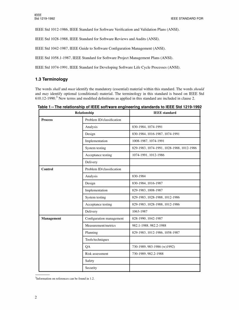
Table 1ÑThe relationship of IEEE software engineering standards to IEEE Std 1219-1992
Relationship IEEE standard
Process
Problem ID/classiÞcation
Analysis 830-1984, 1074-1991
Design 830-1984, 1016-1987, 1074-1991
Implementation 1008-1987, 1074-1991
System testing 829-1983, 1074-1991, 1028-1988, 1012-1986
Acceptance testing 1074-1991, 1012-1986
Delivery
Control
Problem ID/classiÞcation
Analysis 830-1984
Design 830-1984, 1016-1987
Implementation 829-1983, 1008-1987
System testing 829-1983, 1028-1988, 1012-1986
Acceptance testing 829-1983, 1028-1988, 1012-1986
Delivery 1063-1987
Management
ConÞguration management 828-1990, 1042-1987
Measurement/metrics 982.1-1988, 982.2-1988
Planning 829-1983, 1012-1986, 1058-1987
Tools/techniques
QA 730-1989, 983-1986 (w)1992)
Risk assessment 730-1989, 982.2-1988
Safety
Security
IEEESOFTWARE MAINTENANCE Std 1219-1992
3
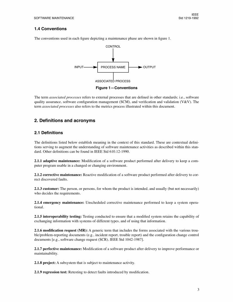
1.4 Conventions
The conventions used in each Þgure depicting a maintenance phase are shown in Þgure 1.
Figure 1ÑConventions
The term
associated processes
refers to external processes that are deÞned in other standards; i.e., softwarequality assurance, software conÞguration management (SCM), and veriÞcation and validation (V&V). Theterm
associated processes
also refers to the metrics process illustrated within this document.
2. DeÞnitions and acronyms
2.1 DeÞnitions
The deÞnitions listed below establish meaning in the context of this standard. These are contextual deÞni-tions serving to augment the understanding of software maintenance activities as described within this stan-dard. Other deÞnitions can be found in IEEE Std 610.12-1990.
2.1.1 adaptive maintenance:
ModiÞcation of a software product performed after delivery to keep a com-puter program usable in a changed or changing environment.
2.1.2 corrective maintenance:
Reactive modiÞcation of a software product performed after delivery to cor-rect discovered faults.
2.1.3 customer:
The person, or persons, for whom the product is intended, and usually (but not necessarily)who decides the requirements.
2.1.4 emergency maintenance:
Unscheduled corrective maintenance performed to keep a system opera-tional.
2.1.5 interoperability testing:
Testing conducted to ensure that a modiÞed system retains the capability ofexchanging information with systems of different types, and of using that information.
2.1.6 modiÞcation request (MR):
A generic term that includes the forms associated with the various trou-ble/problem-reporting documents (e.g., incident report, trouble report) and the conÞguration change controldocuments [e.g., software change request (SCR), IEEE Std 1042-1987].
2.1.7 perfective maintenance:
ModiÞcation of a software product after delivery to improve performance ormaintainability.
2.1.8 project:
A subsystem that is subject to maintenance activity.
2.1.9 regression test:
Retesting to detect faults introduced by modiÞcation.
PROCESS NAME
ASSOCIATED PROCESS
CONTROL
OUTPUTINPUT
IEEEStd 1219-1992 IEEE STANDARD FOR
4
2.1.10 repository:
(A) A collection of all software-related artifacts (e.g., the software engineering environ-ment) belonging to a system. (B) The location/format in which such a collection is stored.
2.1.11 reverse engineering:
The process of extracting software system information (including documenta-tion) from source code.
2.1.12 software maintenance:
ModiÞcation of a software product after delivery to correct faults, toimprove performance or other attributes, or to adapt the product to a modiÞed environment.
2.1.13 system:
A set of interlinked units organized to accomplish one or several speciÞc functions.
2.1.14 user:
The person or persons operating or interacting directly with the system.
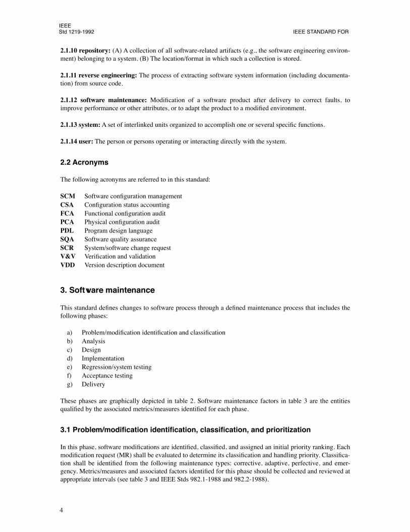
2.2 Acronyms
The following acronyms are referred to in this standard:
SCM
Software conÞguration management
CSA
ConÞguration status accounting
FCA
Functional conÞguration audit
PCA
Physical conÞguration audit
PDL
Program design language
SQA
Software quality assurance
SCR
System/software change request
V&V
VeriÞcation and validation
VDD
Version description document
3. Software maintenance
This standard deÞnes changes to software process through a deÞned maintenance process that includes thefollowing phases:
a) Problem/modiÞcation identiÞcation and classiÞcationb) Analysisc) Designd) Implementatione) Regression/system testingf) Acceptance testingg) Delivery
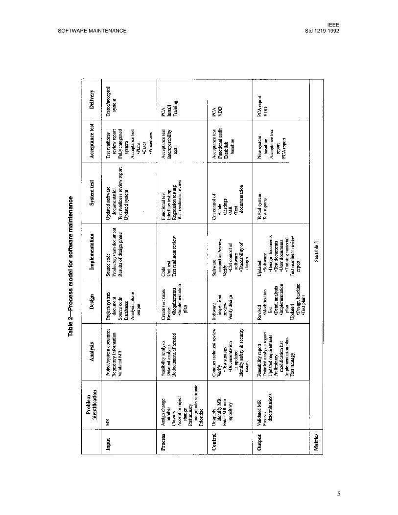
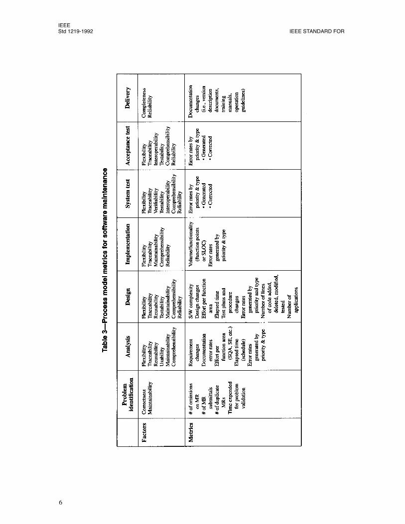
These phases are graphically depicted in table 2. Software maintenance factors in table 3 are the entitiesqualiÞed by the associated metrics/measures identiÞed for each phase.
3.1 Problem/modiÞcation identiÞcation, classiÞcation, and prioritization
In this phase, software modiÞcations are identiÞed, classiÞed, and assigned an initial priority ranking. EachmodiÞcation request (MR) shall be evaluated to determine its classiÞcation and handling priority. ClassiÞca-tion shall be identiÞed from the following maintenance types: corrective, adaptive, perfective, and emer-gency. Metrics/measures and associated factors identiÞed for this phase should be collected and reviewed atappropriate intervals (see table 3 and IEEE Stds 982.1-1988 and 982.2-1988).
IEEESOFTWARE MAINTENANCE Std 1219-1992
5
IEEEStd 1219-1992 IEEE STANDARD FOR
6
IEEESOFTWARE MAINTENANCE Std 1219-1992
7
3.1.1 Input
Input for the problem/modiÞcation identiÞcation and classiÞcation phase shall be an MR.
3.1.2 Process
If a modiÞcation to the software is required, the following determinative activities must occur within themaintenance process:
a) Assign an identiÞcation numberb) Classify the type of maintenancec) Analyze the modiÞcation to determine whether to accept, reject, or further evaluated) Make a preliminary estimate of the modiÞcation size/magnitudee) Prioritize the modiÞcationf) Assign MR to a block of modiÞcations scheduled for implementation
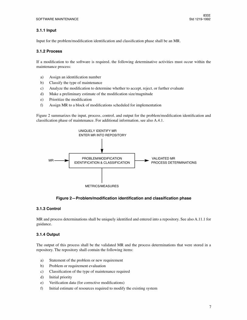
Figure 2 summarizes the input, process, control, and output for the problem/modiÞcation identiÞcation andclassiÞcation phase of maintenance. For additional information, see also A.4.1.
Figure 2ÑProblem/modiÞcation identiÞcation and classiÞcation phase
3.1.3 Control
MR and process determinations shall be uniquely identiÞed and entered into a repository. See also A.11.1 forguidance.
3.1.4 Output
The output of this process shall be the validated MR and the process determinations that were stored in arepository. The repository shall contain the following items:
a) Statement of the problem or new requirementb) Problem or requirement evaluationc) ClassiÞcation of the type of maintenance requiredd) Initial prioritye) VeriÞcation data (for corrective modiÞcations)f) Initial estimate of resources required to modify the existing system
PROBLEM/MODIFICATIONIDENTIFICATION & CLASSIFICATION
UNIQUELY IDENTIFY MRENTER MR INTO REPOSITORY
MR
METRICS/MEASURES
VALIDATED MRPROCESS DETERMINATIONS
IEEEStd 1219-1992 IEEE STANDARD FOR
8
3.2 Analysis
The analysis phase shall use the repository information and the MR validated in the modiÞcation identiÞca-tion and classiÞcation phase, along with system and project documentation, to study the feasibility and scopeof the modiÞcation and to devise a preliminary plan for design, implementation, test, and delivery. Metrics/measures and associated factors identiÞed for this phase should be collected and reviewed at appropriateintervals (see table 3 and IEEE Stds 982.1-1988 and 982.2-1988).
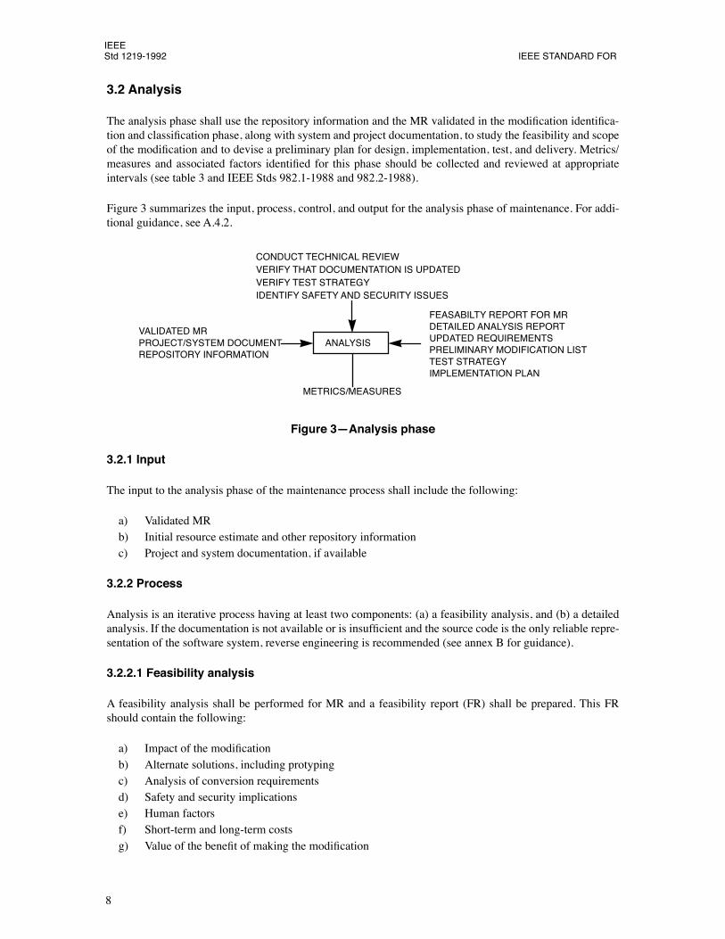
Figure 3 summarizes the input, process, control, and output for the analysis phase of maintenance. For addi-tional guidance, see A.4.2.
Figure 3ÑAnalysis phase
3.2.1 Input
The input to the analysis phase of the maintenance process shall include the following:
a) Validated MRb) Initial resource estimate and other repository informationc) Project and system documentation, if available
3.2.2 Process
Analysis is an iterative process having at least two components: (a) a feasibility analysis, and (b) a detailedanalysis. If the documentation is not available or is insufÞcient and the source code is the only reliable repre-sentation of the software system, reverse engineering is recommended (see annex B for guidance).
3.2.2.1 Feasibility analysis
A feasibility analysis shall be performed for MR and a feasibility report (FR) shall be prepared. This FRshould contain the following:
a) Impact of the modiÞcationb) Alternate solutions, including protypingc) Analysis of conversion requirementsd) Safety and security implicationse) Human factorsf) Short-term and long-term costsg) Value of the beneÞt of making the modiÞcation
ANALYSIS
IDENTIFY SAFETY AND SECURITY ISSUESVERIFY TEST STRATEGYVERIFY THAT DOCUMENTATION IS UPDATEDCONDUCT TECHNICAL REVIEW
VALIDATED MRPROJECT/SYSTEM DOCUMENTREPOSITORY INFORMATION
FEASABILTY REPORT FOR MRDETAILED ANALYSIS REPORTUPDATED REQUIREMENTSPRELIMINARY MODIFICATION LISTTEST STRATEGYIMPLEMENTATION PLAN
METRICS/MEASURES
IEEESOFTWARE MAINTENANCE Std 1219-1992
9
3.2.2.2 Detailed analysis
Detailed analysis shall provide the following:
a) DeÞne Þrm requirements for the modiÞcationb) Identify the elements of modiÞcationc) Identify safety and security issues (see also A.9 and A.10 for guidance)d) Devise a test strategye) Develop an implementation plan
In identifying the elements of modiÞcation (creating the preliminary modiÞcation list), analysts examines allproducts (e.g., software, speciÞcations, databases, documentation) that are affected. Each of these productsshall be identiÞed, and generated if necessary, specifying the portions of the product to be modiÞed, theinterfaces affected, the user-noticeable changes expected, the relative degree and kind of experience requiredto make changes, and the estimated time to complete the modiÞcation.
The test strategy is based on input from the previous activity identifying the elements of modiÞcation.Requirements for at least three levels of test, including individual element tests, integration tests, and user-oriented functional acceptance tests shall be deÞned. Regression test requirements associated with each ofthese levels of test shall be identiÞed as well. The test cases to be used for testing to establish the test base-line shall be revalidated.
A preliminary implementation plan shall state how the design, implementation, testing, and delivery of themodiÞcation is to be accomplished with a minimal impact to current users.
3.2.3 Control
Control of analysis shall include the following:
a) Retrieval of the relevant version of project and system documentation from the conÞguration controlfunction of the organization
b) Review of the proposed changes and engineering analysis to assess technical and economicfeasibility, and assess correctness
c) IdentiÞcation of safety and security issuesd) Consideration of the integration of the proposed change within the existing softwaree) VeriÞcation that all appropriate analysis and project documentation is updated and properly con-
trolledf) VeriÞcation that the test function of the organization is providing a strategy for testing the change(s),
and that the change schedule can support the proposed test strategyg) Review of the resource estimates and schedules and veriÞcation of their accuracyh) Technical review to select the problem reports and proposed enhancements to be implemented in the
new release. The list of changes shall be documented.
Consult A.6, A.7, and A.11.2 for guidance on activities related to veriÞcation and validation, software qual-ity assurance, and software conÞguration management.
At the end of the analysis phase, a risk analysis shall be performed (see also A.8 for guidance). Using theoutput of the analysis phase, the preliminary resource estimate shall be revised, and a decision, that includesthe customer, is made on whether to proceed to the design phase.
3.2.4 Output
The output of the maintenance process analysis phase shall include the following:
IEEEStd 1219-1992 IEEE STANDARD FOR
10
a) Feasibility report for MRsb) Detailed analysis reportc) Updated requirements (including traceability list)d) Preliminary modiÞcation liste) Test strategyf) Implementation plan
3.3 Design
In the design phase, all current system and project documentation, existing software and databases, and theoutput of the analysis phase (including detailed analysis, statements of requirements, identiÞcation of ele-ments affected, test strategy, and implementation plan) shall be used to design the modiÞcation to the sys-tem. Metrics/measures and associated factors identiÞed for this phase should be collected and reviewed atappropriate intervals (see table 3 and IEEE Stds 982.1-1988 and 982.2-1988).
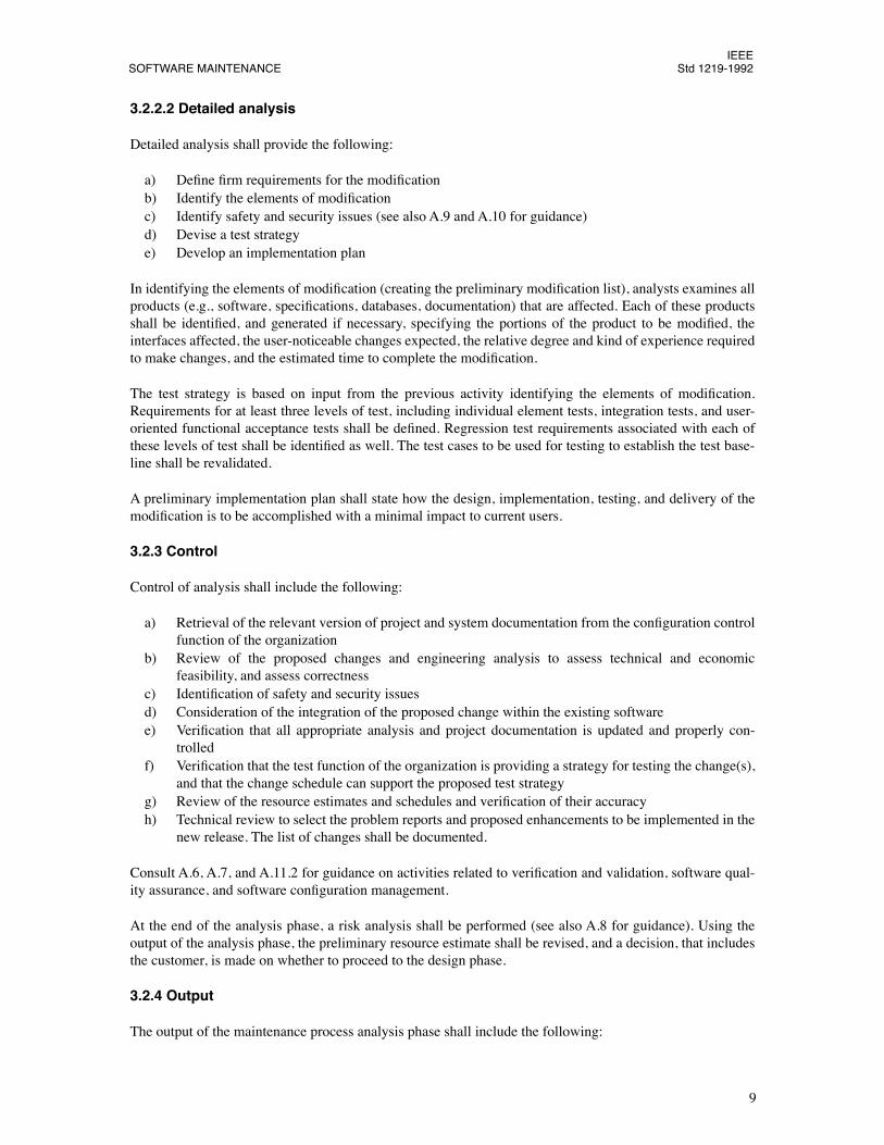
Figure 4 summarizes the input, process, control, and output for the design phase of maintenance. (For addi-tional guidance, see also A.4.3.)
Figure 4ÑDesign phase
3.3.1 Input
Input to the design phase of the maintenance process shall include the following:
a) Analysis phase output, including1) Detailed analysis2) Updated statement of requirements3) Preliminary modiÞcation list4) Test strategy5) Implementation plan
b) System and project documentationc) Existing source code, comments, and databases
3.3.2 Process
The process steps for design shall include the following:
a) Identifying affected software modulesb) Modifying software module documentation (e.g., data and control ßow diagrams, schematics, PDL,
etc.)
DESIGN
METRICS/MEASURES
SYSTEM/PROJECT DOCUMENTANALYSIS PHASE OUTPUTSOURCE CODE, DATABASE
REVISED MODIFICATION LIST
UPDATED DESIGN BASELINEUPDATED TEST PLANSREVISED DETAIL ANALYSIS
VERIFIED REQUIREMENTSREVISED IMPLEMENTATION PLANDOCUMENTED CONSTRAINTS AND RISKS
CONDUCT SOFTWARE INSPECTIONVERIFY THAT DESIGN IS DOCUMENTED
COMPLETE TRACEABILITY OF REQUIREMENTS TO DESIGN
IEEESOFTWARE MAINTENANCE Std 1219-1992
11
c) Creating test cases for the new design, including safety and security issues (for guidance, see alsoA.9 and A.10)
d) Identifying/creating regression tests
e) Identifying documentation (system/user) update requirementsf) Updating modiÞcation list
3.3.3 Control
The following control mechanism shall be used during the design phase of a change:
a) Conduct software inspection of the design in compliance with IEEE Std 1028-1988.
b) Verify that the new design/requirement is documented as a software change authorization (SCA), asper IEEE Std 1042-1987.
c) Verify the inclusion of new design material, including safety and security issues.d) Verify that the appropriate test documentation has been updated.
e) Complete the traceability of the requirements to the design.
Consult A.6, A.7, and A.11.2 for guidance on activities related to veriÞcation and validation, software qual-ity assurance, and software conÞguration management.
3.3.4 Output
The output of the design phase of the maintenance process shall include the following:
a) Revised modiÞcation list
b) Updated design baselinec) Updated test plansd) Revised detailed analysis
e) VeriÞed requirementsf) Revised implementation plang) A list of documented constraints and risks (for guidance, see A.8)
3.4 Implementation
In the implementation phase, the results of the design phase, the current source code, and project and systemdocumentation (i.e., the entire system as updated by the analysis and design phases) shall be used to drivethe implementation effort. Metrics/measures and associated factors identiÞed for this phase should be col-lected and reviewed at appropriate intervals (see table 3 and IEEE Stds 982.1-1988 and 982.2-1988).
Figure 5 summarizes the input, process, control, and output for the implementation phase of maintenance.For additional guidance, see also A.4.4.
3.4.1 Input
The input to the implementation phase shall include the following:
a) Results of the design phaseb) Current source code, comments, and databases
c) Project and system documentation
IEEEStd 1219-1992 IEEE STANDARD FOR
12
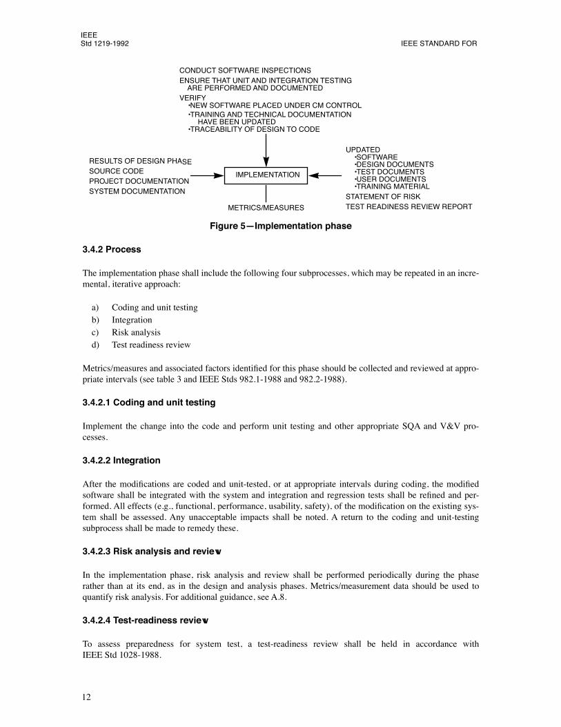
Figure 5ÑImplementation phase
3.4.2 Process
The implementation phase shall include the following four subprocesses, which may be repeated in an incre-mental, iterative approach:
a) Coding and unit testingb) Integrationc) Risk analysisd) Test readiness review
Metrics/measures and associated factors identiÞed for this phase should be collected and reviewed at appro-priate intervals (see table 3 and IEEE Stds 982.1-1988 and 982.2-1988).
3.4.2.1 Coding and unit testing
Implement the change into the code and perform unit testing and other appropriate SQA and V&V pro-cesses.
3.4.2.2 Integration
After the modiÞcations are coded and unit-tested, or at appropriate intervals during coding, the modiÞedsoftware shall be integrated with the system and integration and regression tests shall be reÞned and per-formed. All effects (e.g., functional, performance, usability, safety), of the modiÞcation on the existing sys-tem shall be assessed. Any unacceptable impacts shall be noted. A return to the coding and unit-testingsubprocess shall be made to remedy these.
3.4.2.3 Risk analysis and review
In the implementation phase, risk analysis and review shall be performed periodically during the phaserather than at its end, as in the design and analysis phases. Metrics/measurement data should be used toquantify risk analysis. For additional guidance, see A.8.
3.4.2.4 Test-readiness review
To assess preparedness for system test, a test-readiness review shall be held in accordance withIEEE Std 1028-1988.
IMPLEMENTATION
METRICS/MEASURES
RESULTS OF DESIGN PHASESOURCE CODEPROJECT DOCUMENTATIONSYSTEM DOCUMENTATION
UPDATED ¥SOFTWARE ¥DESIGN DOCUMENTS ¥TEST DOCUMENTS ¥USER DOCUMENTS ¥TRAINING MATERIALSTATEMENT OF RISKTEST READINESS REVIEW REPORT
CONDUCT SOFTWARE INSPECTIONSENSURE THAT UNIT AND INTEGRATION TESTING ARE PERFORMED AND DOCUMENTEDVERIFY ¥NEW SOFTWARE PLACED UNDER CM CONTROL ¥TRAINING AND TECHNICAL DOCUMENTATION
¥TRACEABILITY OF DESIGN TO CODE HAVE BEEN UPDATED
IEEESOFTWARE MAINTENANCE Std 1219-1992
13
3.4.3 Control
The control of implementation shall include the following:
a) Conduct software inspections of the code in compliance with IEEE Std 1028-1988.b) Ensure that unit and integration testing are performed and documented in a software development
folder.c) Ensure that test documentation (e.g., test plan, test cases, and test procedures) are either updated or
created.d) Identify, document, and resolve any risks exposed during software and test-readiness reviews.e) Verify that the new software is placed under software conÞguration management control.f) Verify that the training and technical documentation have been updated.g) Verify the traceability of the design to the code.
Consult A.6, A.7, and A.11.2 for guidance on activities related to veriÞcation and validation, software qual-ity assurance, and software conÞguration management.
3.4.4 Output
The output of the implementation phase shall include the following:
a) Updated softwareb) Updated design documentationc) Updated test documentationd) Updated user documentatione) Updated training materialf) A statement of risk and impact to usersg) Test readiness review report (see IEEE Std 1028-1988)
3.5 System test
System testing, as deÞned in IEEE Std 610.12-1990, shall be performed on the modiÞed system. Regressiontesting is a part of system testing and shall be performed to validate that the modiÞed code does not intro-duce faults that did not exist prior to the maintenance activity. Metrics/measures and associated factors iden-tiÞed for this phase should be collected and reviewed at appropriate intervals (see table 3 andIEEE Stds 982.1-1988 and 982.2-1988).
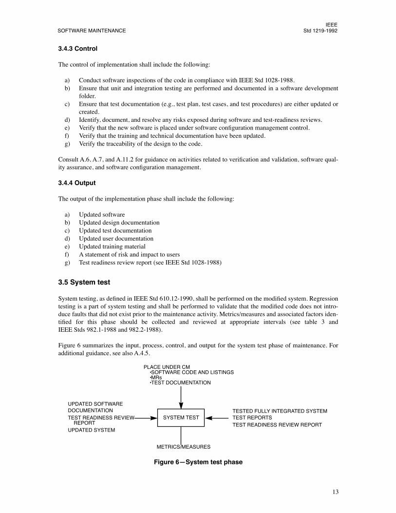
Figure 6 summarizes the input, process, control, and output for the system test phase of maintenance. Foradditional guidance, see also A.4.5.
Figure 6ÑSystem test phase
SYSTEM TEST
METRICS/MEASURES
UPDATED SOFTWAREDOCUMENTATIONTEST READINESS REVIEW
TESTED FULLY INTEGRATED SYSTEMTEST REPORTSTEST READINESS REVIEW REPORT
PLACE UNDER CM ¥SOFTWARE CODE AND LISTINGS ¥MRs ¥TEST DOCUMENTATION
UPDATED SYSTEM REPORT
IEEEStd 1219-1992 IEEE STANDARD FOR
14
3.5.1 Input
Input to the system test phase of maintenance shall include the following:
a) Test-readiness review reportb) Documentation, which includes:
1) System test plans (IEEE 829-1983)2) System test cases (IEEE 829-1983)3) System test procedures (IEEE 829-1983)4) User manuals5) Design
c) Updated system
3.5.2 Process
System tests shall be conducted on a fully integrated system. Testing shall include the performance of
a) System functional testb) Interface testingc) Regression testingd) Test readiness review to assess preparedness for acceptance testing
NOTEÑResults of tests conducted prior to the test-readiness review should not be used as part of the system test reportto substantiate requirements at the system level. This is necessary to ensure that the test organization does not considerthat testing all parts (one at a time) of the system constitutes a Òsystem test.Ó
3.5.3 Control
System tests shall be conducted by an independent test function, or by the software quality assurance func-tion. Prior to the completion of system testing, the test function shall be responsible for reporting the statusof the criteria that had been established in the test plan for satisfactory completion of system testing. The sta-tus shall be reported to the appropriate review committee prior to proceeding to acceptance testing. Softwarecode listings, MRs and test documentation shall be placed under SCM. The customer shall participate in thereview to ascertain that the maintenance release is ready to begin acceptance testing.
Consult A.6, A.7, and A.11.2 for guidance on activities related to veriÞcation and validation, software qual-ity assurance, and SCM.
3.5.4 Output
The output for this phase of maintenance shall include the following:
a) Tested and fully integrated systemb) Test reportc) Test readiness review report
3.6 Acceptance test
Acceptance tests shall be conducted on a fully integrated system. Acceptance tests shall be performed byeither the customer, the user of the modiÞcation package, or a third party designated by the customer. Anacceptance test is conducted with software that is under SCM in accordance with the provisions ofIEEE Std 828-1990, and in accordance with the IEEE Std 730-1989. Acceptance testing, as deÞned inIEEE Std 610.12-1990, shall be performed on the modiÞed system. Metrics/measures and associated factors
IEEESOFTWARE MAINTENANCE Std 1219-1992
15
identiÞed for this phase should be collected and reviewed at appropriate intervals (see table 3 andIEEE Stds 982.1-1988 and 982.2-1988).
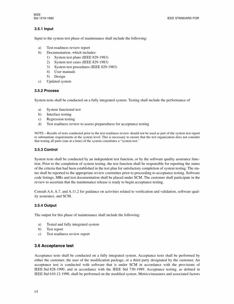
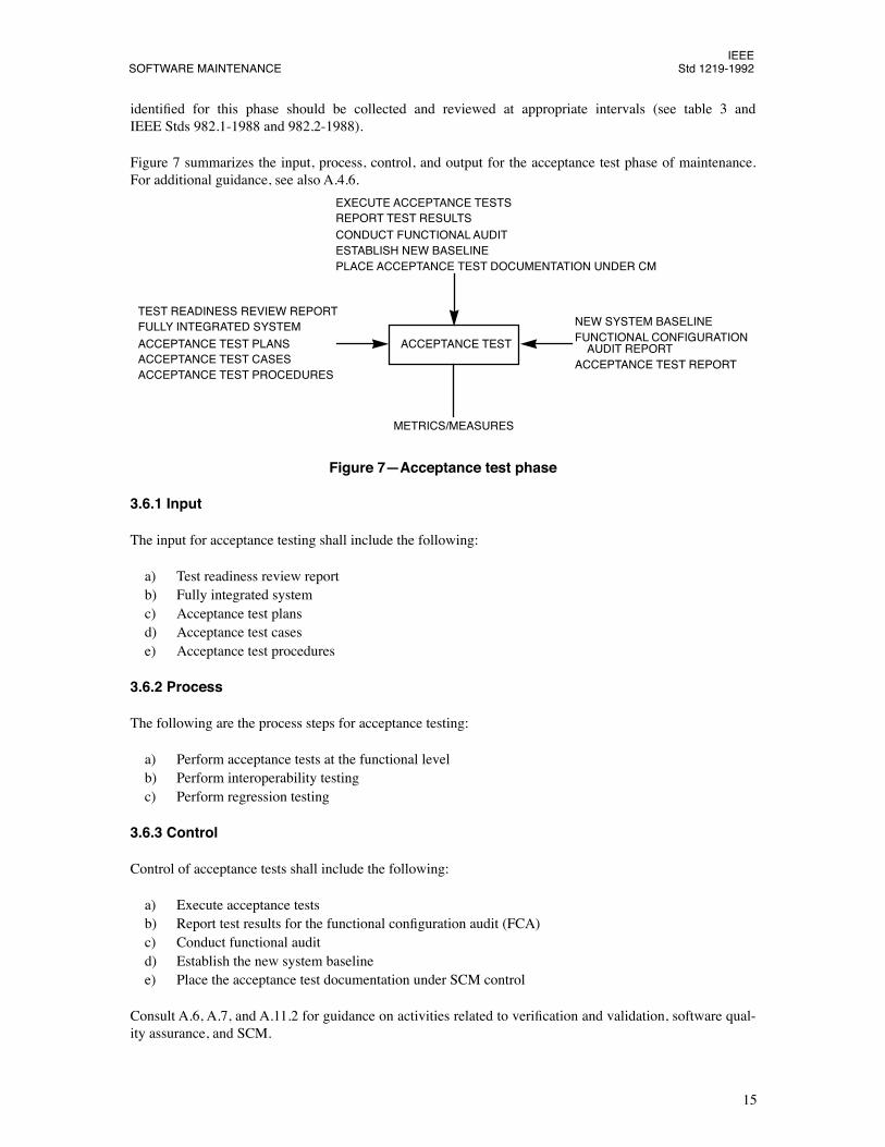
Figure 7 summarizes the input, process, control, and output for the acceptance test phase of maintenance.For additional guidance, see also A.4.6.
Figure 7ÑAcceptance test phase
3.6.1 Input
The input for acceptance testing shall include the following:
a) Test readiness review reportb) Fully integrated systemc) Acceptance test plansd) Acceptance test casese) Acceptance test procedures
3.6.2 Process
The following are the process steps for acceptance testing:
a) Perform acceptance tests at the functional levelb) Perform interoperability testingc) Perform regression testing
3.6.3 Control
Control of acceptance tests shall include the following:
a) Execute acceptance testsb) Report test results for the functional conÞguration audit (FCA)c) Conduct functional auditd) Establish the new system baselinee) Place the acceptance test documentation under SCM control
Consult A.6, A.7, and A.11.2 for guidance on activities related to veriÞcation and validation, software qual-ity assurance, and SCM.
ACCEPTANCE TEST
TEST READINESS REVIEW REPORTFULLY INTEGRATED SYSTEM
ACCEPTANCE TEST PLANSACCEPTANCE TEST CASESACCEPTANCE TEST PROCEDURES
NEW SYSTEM BASELINEFUNCTIONAL CONFIGURATION AUDIT REPORTACCEPTANCE TEST REPORT
EXECUTE ACCEPTANCE TESTSREPORT TEST RESULTSCONDUCT FUNCTIONAL AUDITESTABLISH NEW BASELINEPLACE ACCEPTANCE TEST DOCUMENTATION UNDER CM
METRICS/MEASURES
IEEEStd 1219-1992 IEEE STANDARD FOR
16
3.6.4 Output
The output for the acceptance phase shall include the following:
a) New system baselineb) Functional conÞguration audit report (see IEEE Std 1028-1988)c) Acceptance test report (see IEEE Std 1042-1987)
NOTEÑThe customer shall be responsible for the acceptance test report.
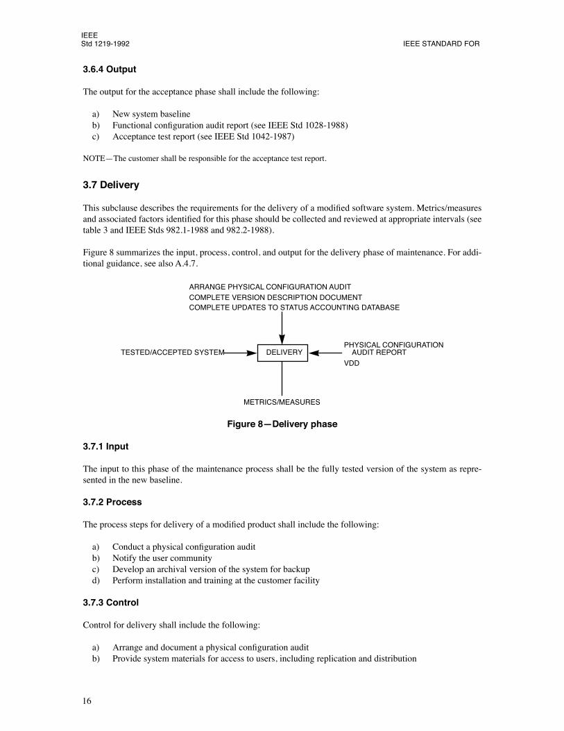
3.7 Delivery
This subclause describes the requirements for the delivery of a modiÞed software system. Metrics/measuresand associated factors identiÞed for this phase should be collected and reviewed at appropriate intervals (seetable 3 and IEEE Stds 982.1-1988 and 982.2-1988).
Figure 8 summarizes the input, process, control, and output for the delivery phase of maintenance. For addi-tional guidance, see also A.4.7.
Figure 8ÑDelivery phase
3.7.1 Input
The input to this phase of the maintenance process shall be the fully tested version of the system as repre-sented in the new baseline.
3.7.2 Process
The process steps for delivery of a modiÞed product shall include the following:
a) Conduct a physical conÞguration auditb) Notify the user communityc) Develop an archival version of the system for backupd) Perform installation and training at the customer facility
3.7.3 Control
Control for delivery shall include the following:
a) Arrange and document a physical conÞguration auditb) Provide system materials for access to users, including replication and distribution
DELIVERYTESTED/ACCEPTED SYSTEMPHYSICAL CONFIGURATION
VDD
AUDIT REPORT
ARRANGE PHYSICAL CONFIGURATION AUDITCOMPLETE VERSION DESCRIPTION DOCUMENTCOMPLETE UPDATES TO STATUS ACCOUNTING DATABASE
METRICS/MEASURES
IEEESOFTWARE MAINTENANCE Std 1219-1992
17
c) Complete the version description document (IEEE Std 1042-1987)d) Complete updates to status accounting databasee) Place under SCM control
Consult A.6, A.7, and A.11.2 for guidance on activities related to veriÞcation and validation, software qual-ity assurance, and SCM.
3.7.4 Output
Output for delivery shall include the following:
a) PCA report (IEEE Std 1028-1988)b) Version description document (VDD)
18
19
Annexes
(These informative annexes are not a part of IEEE Std 1219-1992, IEEE standard for software maintenance, but areincluded for information only.)
Annex AMaintenance Guidelines
(informative)
A.1 DeÞnitions
The deÞnitions listed below deÞne terms as used in this annex.
A.1.1 completeness:
The state of software in which full implementation of the required functions is pro-vided.
A.1.2 comprehensibility:
The quality of being able to be understood; intelligibility, conceivability.
A.1.3 consistency:
Uniformity of design and implementation techniques and notation.
A.1.4 correctness:
The state of software in which traceability, consistency, and completeness are provided.
A.1.5 instrumentation:
The attributes of software that provide for the measurement of usage or identiÞca-tion of errors.
A.1.6 modularity:
Being provided with a structure of highly independent modules.
A.1.7 preventive maintenance:
Maintenance performed for the purpose of preventing problems before theyoccur.
A.1.8 safety:
The ability of a system to avoid catastrophic behavior.
A.1.9 self-descriptiveness:
The extent of a softwareÕs ability to provide an explanation of the implementa-tion of a function or functions.
A.1.10 simplicity:
The provision of implementation of functions in the most understandable manner (usu-ally avoidance of practices that increase complexity).
A.1.11 testability:
The ability of a software to provide simplicity, modularity, instrumentation, and self-descriptiveness.
A.1.12 traceability:
The ability of a software to provide a thread from the requirements to the implementa-tion, with respect to the speciÞc development and operational environment.
A.1.13 veriÞability:
The capability of a software to be veriÞed, proved, or conÞrmed by examination orinvestigation.
IEEEStd 1219-1992 IEEE STANDARD FOR
20
A.2 References
The following standards are directly referenced in this annex. Table 1 provides a cross-reference of IEEEstandards that address various topics related to software maintenance. These standards are binding to theextent speciÞed within the text of this standard and are referenced to avoid duplication of requirements.
IEEE Std 730-1989, IEEE Standard for Software Quality Assurance Plans (ANSI).
4
IEEE Std 828-1990, IEEE Standard for Software ConÞguration Management Plans (ANSI).
IEEE Std 829-1983 (Reaff 1991), IEEE Standard for Software Test Documentation (ANSI).
IEEE Std 982.1-1988, IEEE Standard Dictionary of Measures to Produce Reliable Software (ANSI).
IEEE Std 982.2-1988, IEEE Guide for the Use of IEEE Standard Dictionary of Measures to Produce Reli-able Software (ANSI).
IEEE Std 983-1986 (w1992), IEEE Guide for Software Quality Assurance Planning (ANSI).
5
IEEE Std 1012-1986, IEEE Standard for Software VeriÞcation and Validation Plans (ANSI).
IEEE Std 1028-1988, IEEE Standard for Software Reviews and Audits (ANSI).
IEEE Std 1042-1987, IEEE Guide to Software ConÞguration Management (ANSI).
IEEE Std 1058.1-1987, IEEE Standard for Software Project Management Plans (ANSI).
NBS Special Publication 500-106, Guidance on Software Maintenance.
6
P1228, Software Safety Plans, Draft H, April 27, 1992.
7
A.3 Maintenance planning
Planning for maintenance may include: determining the maintenance effort, determining the current mainte-nance process, quantifying the maintenance effort, projecting maintenance requirements, and developing amaintenance plan. IEEE Std 1058.1-1987 may also be used for guidance in maintenance planning.
A.3.1 Determine maintenance effort
The Þrst step in the maintenance planning process is an analysis of current service levels and capabilities.This includes an analysis of the existing maintenance portfolio and the state of each system within that port-folio. At the system level, each system should be examined to determine the following:
4
IEEE publications are available from the Institute of Electrical and Electronics Engineers, Service Center, 445 Hoes Lane, P.O. Box1331, Piscataway, NJ 08855-1331, USA.
5
IEEE Std 983-1986 has been withdrawn; however, copies can be obtained from the IEEE Standards Department, IEEE Service Center,445 Hoes Lane, P.O. Box 1331, Piscataway, NJ 08855-1331, USA.
6
NBS publications are available from the Superintendent of Documents, US Government Printing OfÞce, P.O. Box 37082, Washington,DC 20013-7082, USA.
7
This authorized standards project was not approved by the IEEE Standards Board at the time IEEE Std 1219-1992 went to press. It isavailable from the IEEE Service Center, 445 Hoes Lane, P.O. Box 1331, Piscataway, NJ 08855-1331, USA.
IEEESOFTWARE MAINTENANCE Std 1219-1992
21
a) Age since being placed in productionb) Number and type of changes during lifec) Usefulness of the systemd) Types and number of requests received for changese) Quality and timeliness of documentationf) Any existing performance statistics (CPU, disk I/O, etc.)
Descriptions at the portfolio level can assist in describing the overall effort and needs of the maintenancearea. This includes the amount and kinds of functional system overlap and gaps within the portfolio architec-ture.
The reviews of the maintenance staff and the maintenance procedures are also necessary to determine theoverall maintenance effort. The analysis at this stage is simply to gather those measures needed to determinethe following:
a) The number of maintainers, their job descriptions, and their actual jobsb) The experience level of the maintenance staff, both industry-wide and for the particular applicationc) The rate of turnover and possible reasons for leavingd) Current written maintenance methods at the systems and program levele) Actual methods used by programming stafff) Tools used to support the maintenance process and how they are used
Information at this stage is used to deÞne the baseline for the maintenance organization and provide a meansof assessing the necessary changes.
A.3.2 Determine current maintenance process
The maintenance process is a natural outgrowth of many of the baseline measures. Once those measureshave been collected, the actual process needs to be determined. In some organizations, the process is tailoredto the type of maintenance being performed and can be divided in several different ways. This can includedifferent processes for corrections vs. enhancements, small changes vs. large changes, etc. It is helpful toclassify the maintenance approaches used before deÞning the processes.
Each process will then be described by a series of events. In general, the ßow of work is described fromreceipt of a request to its implementation and delivery.
A.3.3 Quantify maintenance effort
Each step in the process needs to be described numerically in terms of volumes or time. These numbers canthen be used as a basis to determine the actual performance of the maintenance organization.
A.3.4 Project maintenance requirements
At this stage, the maintenance process needs to be coupled to the business environment. A review of futureexpectations should be completed and may include
a) Expected external or regulatory changes to the systemb) Expected internal changes to support new requirementsc) Wish-list of new functions and featuresd) Expected upgrades for performance, adaptability, connectivity, etc.e) New lines of business that need to be supportedf) New technologies that need to be incorporated
IEEEStd 1219-1992 IEEE STANDARD FOR
22
These need to be quantiÞed (or sized) to determine the future maintenance load for the organization.
A.3.5 Develop maintenance plan
The information collected will provide a basis for a new maintenance plan. The plan should cover four mainareas:
a) Maintenance processb) Organizationc) Resource allocationsd) Performance tracking
Each of these issues are addressed and imbedded in the Þnal maintenance plan. The actual process should bedescribed in terms of its scope, the sequence of the process, and the control of the process.
A.3.5.1 Process scope
The plan needs to deÞne the boundaries of the maintenance process. The process begins at some point(receipt of the request) and will end with some action (delivery and sign-off). In addition, the differencebetween maintenance and development should be addressed at this point. Is an enhancement considered tobe a new development, or maintenance? At what point does a newly developed system enter the mainte-nance process?
Another issue that should be deÞned within the scope is whether and how the maintenance process will becategorized. Will there be differences between reporting and other types of maintenance? Will adaptationsand enhancements be considered within the same process or will they be handled differently?
A.3.5.2 Process sequence
The overall ßow of work (and paper) needs to be described. This should include the following:
a) Entry into automated SCM and project management systemsb) Descriptions of each process step and their interfacesc) The data ßow between processes
The sequence should use the process described in this standard as a guideline.
A.3.5.3 Process control
Each step in the process should be controlled and measured. Expected levels of performance should bedeÞned. The control mechanisms should be automated, if possible. The control process should follow thestandards set forth in this document.
A.3.5.4 Organization
Staff size can be estimated from the current work load and estimates of future needs. This estimate may alsobe based on the expected productivity of each step in the process.
A.3.5.5 Resource allocation
An important part of the maintenance plan is an analysis of the hardware and software most appropriate tosupport the organizationÕs needs. The development, maintenance, and target platforms should be deÞned anddifferences between the environments described. Tool sets that enhance productivity should be identiÞed
IEEESOFTWARE MAINTENANCE Std 1219-1992
23
and provided. The tools should be accessible by all who need them, and sufÞcient training should be pro-vided so that their use is well understood.
A.3.5.6 Tracking
Once the process is in place, it should be tracked and evaluated to judge its effectiveness. If each step in theprocess has measurement criteria, it should be a straightforward process to collect and evaluate performanceover time.
A.3.5.7 Implementation of plan
Implementing a maintenance plan is accomplished in the same way that any organizational change is per-formed. It is important to have as much technical, professional, and managerial input as possible when theplan is being developed.
A.4 Maintenance process
The phases presented herein mirror those in the standard.
A.4.1 Problem/modiÞcation identiÞcation and classiÞcation
Each system/software and modiÞcation request should be evaluated to determine its classiÞcation and han-dling priority and assignment for implementation as a block of modiÞcations that will be released to the user.A suggested method for this is to hold a periodic review of all submitted items. This provides a regular,focused forum and helps prevent the review/analyze/design/implement/test process (which may be iterative)from stalling due to lack of direction. It also increases awareness of the most requested and most criticalitems. An agenda should be distributed prior to the meeting listing the items to be classiÞed and prioritized.
The frequency and duration for modiÞcation classiÞcation review meetings should be project-dependent. Aguideline might be to consider them as status reviews rather than as technical reviews. Using this guideline,if, after the Þrst few sessions, the reviews take more than an hour or so, their frequency should be increasedto as often as weekly. If review time still seems insufÞcient, determine whether one of the following casesapplies and handle accordingly:
a) Discussion is focused on major system enhancements (perfective maintenance). This may requireanalysis/review cycles of a development magnitude, rather than at a sustaining maintenance level.
b) The system is new, and design/implementation problems require a signiÞcant maintenance effortimmediately following delivery. A suggested strategy, to be used where the impact to operations isacceptable, is to classify the MRs as corrective/adaptive/perfective/preventive and integrate theminto sets that share the same design areas. Then, rather than prioritizing by individual MR, prioritizeby set. This minimizes repetition of design, code, test, and delivery tasks for the same code modules.In this case, review meetings may be longer and more frequent until the system is stabilized. A long-term plan should have a goal of gradually reducing the review meeting overhead.
c) The system is aging, and system replacement or reverse engineering and redesign are under consid-eration.
These are not the only possible cases. They are described to highlight the importance of understanding thegoals for classifying modiÞcations as they apply to a particular system.
IEEEStd 1219-1992 IEEE STANDARD FOR
24
ModiÞcation requests should be assigned a priority from
a) The MR author or a designated representativeb) A knowledgeable userc) A domain expertd) Software engineers (depending on the project, this may include representatives of system analysis
and design, development, integration, test, maintenance, quality control, and SCM), ore) Project management
The following criteria should be considered:
a) Rough resource estimate, which may be derived from1) Relative ease/difÞculty of implementation2) Approximate time to implement given available human and system resources
b) Expected impact to current and future users1) General statement of beneÞts2) General statement of drawbacks
c) Assignment to an implementation of a block of modiÞcations that are scheduled to minimize theimpact on the user
Thorough, low-level cost and impact studies should be performed in the analysis phase, but general cost esti-mates and statements of impact are desirable for initial classiÞcation. Since this is an iterative process, it islikely that handling priority may change during the phases that follow.
A.4.2 Analysis
A modiÞcation request may generate several system-level functional, performance, usability, reliability, andmaintainability requirements. Each of these may be further decomposed into several software, database,interface, documentation, and hardware requirements. Involvement of requesters, implementers, and users isnecessary to ensure that requirement(s) are unambiguous statements of the request.
Software change impact analysis should
a) Identify potential ripple effectsb) Allow trade-offs between suggested software change approaches to be consideredc) Be done with the help of documentation abstracted from the source coded) Consider the history of prior changes, both successful and unsuccessful
The following should be included in a detailed analysis:
a) Determine if additional problem analysis/identiÞcation is requiredb) Record acceptance or rejection of the proposed change(s)c) Develop an agreed-upon project pland) Evaluate any software or hardware constraints that may result from the changes and that need con-
sideration during the design phasee) Document any project or software risks resulting from the analysis to be considered for subsequent
phases of the change life cyclef) Recommend the use of existing designs, if applicable
A.4.3 Design
Actual implementation should begin during this phase, while keeping in mind the continued feasibility ofthe proposed change. For example, the engineering staff may not fully understand the impact and magnitude
IEEESOFTWARE MAINTENANCE Std 1219-1992
25
of a change until the design is complete, or the design of a speciÞc change may be too complex to imple-ment.
The vehicles for communicating the updated design are project/organization-dependent and may includeportions of a current design speciÞcation, software development Þles, and entries in software engineeringcase tool databases. Other items that may be generated during this phase include a revised analysis, revisedstatements of requirements, a revised list of elements affected, a revised plan for implementation, and arevised risk analysis.
The speciÞcs of the design process may vary from one project to the next and are dependent on such vari-ables as tool use, size of modiÞcation, size of existing system, availability of a development system, andaccessibility to users and requesting organizations. Product characteristics should also be evaluated whendeveloping the design so that decisions on how modules of software will be changed will take into consider-ation the reliability and future maintainability of the total system, rather than focusing on expediency.
A.4.4 Implementation
The primary inputs to this phase are the results of the design phase. Other inputs required for successful con-trol of this phase include the following:
a) Approved and controlled requirements and design documentationb) An agreed-upon set of coding standards to be used by the maintenance staffc) Any design metrics/measurement that may be applicable to the implementation phase (these met-
rics/measures may provide insight into code that may be complex to develop or maintain)d) A detailed implementation schedule, noting how many code reviews will take place and at what
levele) A set of responses to the deÞned risks from the previous phase that are applicable to the testing
phase
Risk analysis and review should be performed periodically during this phase rather than at its end, as in thedesign and analysis phases. This is recommended because a high percentage of design, cost, and perfor-mance problems and risks are exposed while modifying the system. Careful measurement of this process isnecessary, and becomes especially important if the number of iterations of the coding and unit testing andintegration subprocesses is out of scope with the modiÞcation. If this is found true, the feasibility of thedesign and/or modiÞcation request may need reassessment, and a return to the design, analysis, or even themodiÞcation identiÞcation and classiÞcation phase may be warranted.
Prior to a review, the following information may be prepared and provided to attendees:
a) Entry criteria for system testb) Resource allocation and need schedulec) Detailed test scheduled) Test documentation formse) Anomaly resolution proceduresf) SCM proceduresg) Exit criteria for system testh) Lower-level test results
Attendees may include the following:
a) The MR author, a designated representative, or a knowledgeable userb) A domain expert
IEEEStd 1219-1992 IEEE STANDARD FOR
26
c) Software engineers (depending on the project, this may include representatives of system analysisand design, development, integration, test, maintenance, quality control, and SCM)
d) Project management
A.4.5 System test
It is essential to maintain management controls over the execution of system tests to ensure that the non-technical issues concerning budget and schedule are given the proper attention. This function also ensuresthat the proper controls are in place to evaluate the product during testing for completeness and accuracy.
System tests should be performed by an independent test organization, and may be witnessed by the cus-tomer and the end-user. System test is performed on software that is under SCM in accordance with the pro-visions of IEEE Std 828-1990.
8
Software quality assurance is conducted in accordance with the provisionsof IEEE Std 730-1989. The system test is performed with as complete a system as is possible, using simula-tion/stimulation to the smallest degree possible. Functions are tested from input to output.
For maintenance releases, it is possible that other testing may have to be done to satisfy requirements tointeract with other systems or subsystems. It may also be necessary to conduct testing to validate that faultsare not introduced as a result of changes.
System tests should be conducted on a fully integrated system. Simulation/stimulation may be used in caseswhere it is not possible to have the completely integrated system in the test facility. However, its use shouldbe minimized. If utilized, it should be identiÞed and evaluated/justiÞed.
The organization that is responsible for system tests should be independent of the software developers anddesigners, but these organizations may be used as a resource of test personnel. Control of software builds,and all pertinent Þles (source, object, libraries, etc.) during a system test should be done by the SCMfunction. Controls to ensure product integrity are executed by the software quality assurance function. Theyshould ensure that the changes to the products that are submitted are in fact authorized and technicallycorrect.
If changes have been made to the software, or test cases, since the software has been delivered, then it maybe necessary to run regression and unit tests during the analysis phase in order to establish the productbaseline.
A.4.6 Acceptance test
The acceptance test is performed to ensure that the products of the modiÞcation are satisfactory to the cus-tomer. The products include the software system and the documentation necessary to support it. The culmi-nation of the acceptance test is usually the completion of a functional audit and a physical audit (seeIEEE Std 1028-1988).
For maintenance releases, it is possible that other testing may have to be done to satisfy requirements tointeract with other systems or subsystems. It may also be necessary to conduct testing to validate that faultsare not introduced as a result of changes.
Acceptance tests should be conducted on a fully integrated system. Simulation and/or stimulation may beused in cases where it is not possible to have the completely integrated system in the test facility. However,its use should be minimized. This requirement may be modiÞed to include the case where lower-level testingis performed. The customer, or the customerÕs representative, is responsible for determining the facility
8
Information on annex references can be found in A.2.
IEEESOFTWARE MAINTENANCE Std 1219-1992
27
requirements that are necessary. These requirements are documented by the developer in the modiÞcationplan. Acceptance test facilities may be provided by either the developer or the customer, or a combination ofboth.
Results of tests conducted prior to the acceptance test readiness review may be used by the customer toreduce the scope of acceptance tests. If this is done, the customer should document, in the acceptance testreport, which results were taken from previous tests.
Prior to the completion of acceptance testing, the test organization should be responsible for reporting thestatus of the criteria that had been established in the test plan for satisfactory completion of acceptance test-ing. The status should be reported to the appropriate review committee. The customer, or the customerÕs rep-resentative, should chair the review group and evaluate the exit criteria to ensure that the maintenancerelease is ready for delivery to the end-user.
A.4.7 Delivery
Based on how the users access the system, the delivery may entail replacing the existing system with thenew version, duplication of the conÞguration controlled master for delivery to remote users, or digitaltransmission.
To reduce the risks associated with installation of the new version of a software system, project managementshould plan for and document alternative installation procedures that may insure minimal impact on the sys-tem users due to unforeseen software failures not detected during testing. The planning should address time-critical factors (e.g., date/times available for installation, critical milestones of the users, etc.) and restora-tion/recovery procedures.
When a system modiÞcation affects user interfaces or is a signiÞcant modiÞcation of functionality, usertraining may be necessary. This can include formal (classroom) and non-formal methods. When the modiÞ-cations result in signiÞcant documentation changes, user training should be considered.
SCM is responsible for backing up the system. To ensure recovery, the backup should consist of the existingsystem version as well as the new version. To facilitate disaster recovery, complete copies of the systembackup should be archived at an off-site location. The backup should consist of source code, requirementdocumentation, design documentation, test documentation (including test case data), and the support envi-ronment [i.e., operating system, compiler, assembler, test driver(s), and other tools].
A.5 Maintenance forms
Recording, tracking, and implementing software maintenance requires that various forms be completed andmanaged. What follows is a list of forms that may be used to perform maintenance, and the IEEE standardthat explains their format and usage.
a) Test LogÑIEEE Std 829-1983
b) Test Incident ReportÑIEEE Std 829-1983
c) Test Summary ReportÑIEEE Std 829-1983
d) Test Design SpeciÞcationÑIEEE Std 829-1983
e) System/Software Change RequestÑIEEE Std 1042-1987
f) Software Change AuthorizationÑIEEE Std 1042-1987
IEEEStd 1219-1992 IEEE STANDARD FOR
28
A.6 VeriÞcation and validation (V&V)
IEEE Std 1012-1986 should be used to verify and validate that all maintenance requirements are met.
A.7 Software quality assurance
Software quality assurance should be considered when any modiÞcations are made to an existing system. AmodiÞcation to one segment of the system can cause errors to appear somewhere else. Other concerns caninclude: version control, new documentation release, etc. To ensure that quality is maintained for all modiÞ-cations, standards as stated in IEEE Std 730-1989, and IEEE Std 983-1986 should be adhered to.
Continuing product quality assurance includes the following:
a) Adherence to the maintenance plan and approach
b) Testing (including regression testing)
c) Revalidation activities
d) RecertiÞcation activities
The same types and levels of assurance (e.g., inspections, reviews, audits, veriÞcation and validation, evalu-ation of metric data, records) should be conducted as were performed during development; the degree andconduct of these activities is speciÞed in the software maintenance plan. Special care should be given toensuring that the original system documentation continues to describe the actual product; during operationaluse, the time criticality of effecting a repair to the product often results in the lack of related changes to thedocumentation, with concomitant loss of conÞguration control. Similarly, the operational facility should beable to maintain the distinction between proposed Þxes to the software product needed to provide an imme-diate resolution of a critical problem; adopted Þxes that, due to time-criticality, should be utilized prior tohaving been authorized; and those corrections that, through testing, revalidation, and recertiÞcation, havebeen ofÞcially authorized.
A.8 Risk assessment
Software maintenance activities consume considerable resources to implement software changes in existingsystems. Traditionally, systems are tested to detect defects in the software. Since defects in various softwareworkproducts cause failures with different consequences, the signiÞcance (or risk) of each failure/defectvaries.
Software risk is deÞned as the potential loss due to failure during a speciÞc time period. Risk is measured asa product of the frequency or likelihood of loss and the magnitude or level of exposure. Risk assessmentbegins with an analysis of external exposureÑdetermination of the magnitude of loss that can result frominvalid actions. The external exposure is mapped onto the system to determine the magnitude of loss causedby faults in individual software workproducts. The likelihood of failure for each workproduct is based on itsuse, veriÞcation, validation, adaptability, and size characteristics.
In the context of maintenance, the failure can be product- or process-oriented. That is, the failure of theproduct (i.e., errors in function and performance) and process (i.e., inaccurate estimates) have the potentialof increasing costs of the product and are therefore considered risks. Risk abatement techniques for productrisks include testing and maintainability measurement. Risk abatement for the process includes softwarechange impact analysis.
IEEESOFTWARE MAINTENANCE Std 1219-1992
29
To measure software risk, several functions should be performed: external exposure identiÞcation, structuralexposure analysis, and software failure likelihood estimation. The following is an outline of these functionsas they pertain to software maintenance risk assessment.
A.8.1 External exposure identiÞcation
The external exposure identiÞcation function has two primary objectives. The Þrst is to determine whatactions in the environment outside of the software can contribute to loss. The second objective is to assessthe signiÞcance of the loss.
To this end, the procedure involves the following steps:
a)
DeÞnition of environmental hazards.
Determine how the organization intends to use the softwaresystem, and potential hazards such as Þnancial troubles, explosions, incorrect patient treatment, mis-information, loss of life, and like accidents.
b)
IdentiÞcation of accident sequences.
Investigate how accidents can occur and record them in eventtrees, scenarios, or annotated event-sequence diagrams.
c)
Failure mode analysis.
Identify failure modes from accident sequences and record them in faulttrees. Key failure areas are identiÞed by working backwards in the fault tree.
d)
Consequence analysis.
Determine the consequence of the faults by weighting the loss estimated foreach accident scenario. Since this has a wide range of factors and conditions, care should be taken tofocus on the key failures.
A.8.2 Structural exposure analysis
Structural exposure analysis is performed to discover how and where software faults can contribute to lossesidentiÞed in the external exposure assessment. The objective of this function is to assign exposure levels toindividual workproducts based on their capability to cause failures. The procedure includes the followingactivities:
a)
Identify software failure modes.
Indicate where erroneous information can contribute to loss andinvestigate how the software can fail as a result.
b)
Determine workproduct fault potential.
Locate the potential faults related to the fault modes andidentify associated relationships between faults and losses.
c)
Analyze mode use.
Locate where potentially faulty workproducts are used.
d)
Compute workproduct exposure.
Estimate the module exposure by summing its potential loss for allaccident scenarios to which it is related.
A.8.3 Software failure likelihood
The objective of the software failure likelihood function is to predict failure likelihood from workproductand maintenance process characteristics. As software testing proceeds, information about the testing processis used to update or conÞrm our initial estimates of failure likelihood. The likelihood of software failuredepends on the number of faults in a workproduct and the probability that the fault will be encountered inthe operation of the system. That is, failure likelihood depends on the number of faults and the probabilitythat the faults will cause failures. Risks for each workproduct is determined by the probability of each typeof failure times the costs of that failure.
IEEEStd 1219-1992 IEEE STANDARD FOR
30
A.9 Safety
Safety is the ability of a system to avoid catastrophic behavior. Safety requirements may identify criticalfunctions whose failure may be hazardous to people or property. The results of the procedure described inA.8.1 may also be applicable. Draft standard P1228 contains information that may be used to create andmaintain systems.
A.10 Security
The degree to which the system and information access needs to be protected can have an effect on the man-ner in which the system is maintained. A system is secure if unauthorized personnel cannot get at protectedinformation and to the system itself.
Security during the maintenance process should ensure the following:
a) The integrity of the system is preserved by ensuring that only authorized personnel have access tothe system and only authorized changes are implemented. This is accomplished in cooperation withSCM and SQA.
b) Security features implemented during system development are not compromised, either by inadvert-ent action or failure to comply with the existing security requirements.
c) New functions added to the system are compatible with the existing security features.
A.11 Software conÞguration management (SCM)
Software conÞguration management (SCM) is a critical element of the software maintenance process. Con-formance to IEEE Std 828-1990 and IEEE Std 1042-1987 should be adhered to. SCM, a procedure-drivenprocess, depends on sound, workable, and repeatable procedures to implement the software engineeringrelease function. The procedures should provide for the veriÞcation, validation, and certiÞcation of each steprequired to identify, authorize, implement, and release the software product. These procedures should alsodeÞne the methods used to track the change throughout the maintenance process, to provide the requiredtraceability, to ensure the integrity of the product, to keep project management informed with periodicreports, and to document all the activities involved. During the implementation of the software engineeringrelease process, SCM has responsibilities in each of the major categories of SCM; i.e., conÞguration identi-Þcation, conÞguration audits, change control, and status accounting.
SCM of documentation during system test should be done by the SCM function. The documents to be man-aged are
a) System documentation
b) Software code and listings
c) MRs
d) Test documentation
Although SCM is not very involved during the initial phases of traditional software development, SCMshould be actively pursued throughout the entire software maintenance process. Failure to provide rigorousSCM can result in chaos during the maintenance process. The following items address the SCM require-ments that should prevail during each phase of the maintenance process as deÞned in this standard.
IEEESOFTWARE MAINTENANCE Std 1219-1992
31
A.11.1 Problem/modiÞcation identiÞcation and classiÞcation
The SCM process is the principal element of the problem identiÞcation phase of software maintenance.SCM is responsible for receiving and logging the problem (corrective, adaptive, corrective) into the conÞgu-ration status accounting (CSA) system (IEEE Std 1042-1987). SCM personnel are responsible for routingthe problem to the proper personnel (e.g., system/software engineering, test) for validation and evaluation ofthe problem. SCM provides tracking and coordination of the problem documentation during this phase.
A.11.2 Analysis
During the analysis phase, it is an SCM responsibility to provide up-to-date documentation to the personnelperforming the analysis (e.g., systems/software engineering). SCM should also provide up-to-date listings ofthe source code and accurate CSA reports showing the current status of the problem.
At the completion of the analysis phase, it is an SCM responsibility to ensure the analysis results are pre-sented to a review board (an SCM activity). The review board provides visibility and tracking into the prob-lem resolution since it is responsible for authorizing further analysis or implementation. The review boardassigns the problems approved for implementation to a software engineering release (block change) pack-age. Although each problem is implemented independently, control is done on a block of problems associ-ated via the software engineering release. SCM is responsible for documenting the proceedings of thereview board and updating the CSA records associated with the problem.
A.11.3 Design
During the design phase, SCM is responsible for ensuring that the design personnel have up-to-date docu-mentation from the system library. It is crucial that design personnel receive any changes to documentationas soon as possible after receipt. It is an SCM responsibility to archive and safeguard software inspection/review results and other design data provided by the design personnel. In an automated design environment(e.g., computer-aided software engineering [CASE]), SCM may be required to provide assistance to thedesign personnel in maintaining version control. SCM is expected to provide assistance and guidance todesign personnel in the selection and usage of consistent naming conventions.
At the completion of the design phase, it is a conÞguration management responsibility to ensure that designdocumentation is placed in safekeeping and receives SCM control to protect the integrity of the design prod-uct. In automated systems, conÞguration management is responsible for ensuring rigorous version control.
A.11.4 Implementation
During implementation, SCM is responsible for providing the programmers with copies of the modules to bechanged and ensuring rigorous version control. In situations where multiple changes are made to a singlemodule, SCM is responsible for ensuring proper staging to prevent losing changes. This requires completecooperation and coordination between SCM and the maintenance team. SCM should notify the maintenanceteam when updated requirement or design data becomes available.
SCM is responsible for maintaining conÞguration control over all the support tools used in the softwaremaintenance process. Control of the tools (i.e., compilers, assemblers, operating systems, link editors) iscrucial to avoid major impacts to the maintenance schedule and in preventing unnecessary re-work.
At the completion of the implementation phase, SCM is responsible for collecting all the modules that havebeen changed and placing them in secure library facilities. If a software development folder concept is used,SCM should ensure that each is placed under conÞguration control. SCM is often responsible for regenerat-ing the system (compile, link, etc.) and making it available for the test personnel. This is a good practice that
IEEEStd 1219-1992 IEEE STANDARD FOR
32
ensures consistent results and products for the test group. The librarian of a chief programmer team may per-form this SCM task.
SCM is responsible for ensuring that all the scheduled changes are included in the release package and madeavailable for systems testing. The entire release package is subjected to a physical audit by software SCMand validated by software quality assurance. The audit veriÞes and validates that all the items (e.g., docu-ment updates, test plans/procedures, version descriptions, etc.) are complete. After the successful comple-tion of the audit, the release package is presented to a review board for approval to proceed with systemstesting. This approval process helps reduce wasting system resources for testing when a product is not ready,and provides a substantial cost/schedule beneÞt.
SCM is responsible for updating the CSA database with the results of the review board decisions. Updatedstatus reports are produced for management and the maintenance team. The results and reports generated bythe audit are archived and become a permanent part of the release package documentation.
A.11.5 System testing
During the system testing phase, SCM is responsible for ensuring the integrity of
a) Test-case data
b) The software product on suitable media
c) Other test material
SCM provides the test group with up-to-date test material as requested. In test environments that are auto-mated, SCM is responsible for maintaining version control over the test material (e.g., test-case drivers,regression test-case data, etc.).
When system testing is complete, SCM is responsible for archiving test material for the test group. SCMadds the test-report data to the archived release package documentation. Problems encountered during test-ing are documented and entered into the CSA database by SCM.
A.11.6 Acceptance testing
SCM provides total control of all the material made available to support acceptance testing. This material isreturned to SCM at the completion of acceptance testing. SCM adds the acceptance test-report data to thearchived release package documentation. Problems encountered during testing are documented and enteredinto the CSA database by SCM.
The review board is presented with all the test results, along with recommendations from each group in themaintenance team to allow an informed decision on the suitability of the system for delivery to the usercommunity. SCM updates the CSA database with the results of the review board decision and provides man-agement with current status reports.
A.11.7 Delivery
After approval by the review board and concurrence by project management, SCM is responsible for deliv-ery of the system to the user community. Based on how the users access the system, the delivery may entailreplacing the existing system with the new version, duplication from a master for delivery to remote users,or digital transmission to the users. Irrespective of the method, SCM is responsible for preparing and dis-seminating the system.
IEEESOFTWARE MAINTENANCE Std 1219-1992
33
In addition to the physical delivery of the system, SCM is responsible for updating the conÞguration indexrecords to reßect the new version and archiving the complete system, including all release package data.SCM should provide copies of the entire system for disaster recovery storage.
A.12 Metrics/measures
Establishing and implementing a metrics plan is critical for providing insight regarding an organizationÕslevel of productivity as well as the quality of the software maintained by that organization. Additional guid-ance in the form of deÞnitions, methodologies and rationale for implementing a metrics plan is provided inIEEE Stds 982.1-1988 and 982.2-1988. Metrics/measures captured for maintenance should enable the man-ager to manage the process and the implementor to implement the process.
To initialize a metrics process, management needs to identify technical factors that reßect the technical qual-ity as well as management quality (i.e., effective use of schedule and resources) of the software being main-tained. Once these factors are identiÞed as indicators, then measures should be developed that correspond tothe technical factors and quantify those technical factors. It is suggested that the selection of the technicalfactors and their corresponding metrics/measures be optimized such that only the factors that are most perti-nent to the speciÞc phase of the maintenance process are addressed during that respective phase of the main-tenance process.
Once these are identiÞed, a cost-beneÞt analysis should be performed to determine the best value that can beachieved by the organization (in terms of increased productivity and overall better management of the pro-cess) in exchange for the effort expended to collect and analyze the metrics/measurement data. At the veryminimum, effort in terms of work hours should be collected and converted to cost using the organizationÕsinternal labor rate. Additionally, some measure of functionality as well as the error rates generated and clas-siÞed by priority and type should be collected.
Some common measures of functionality are source lines of code (SLOC), function points, and featurepoints. Whatever method is chosen, it should be well-deÞned and agreed upon within the organization. Toolsused for metrics/measurement collection, analysis, and assessment should be validated, calibrated, and usedconsistently throughout the organization.
In the world of software maintenance there are three major cost drivers that dominate the effort expendedduring the software maintenance process. These are documentation, communication and coordination, andtesting. Therefore, any software maintenance metrics plan should include metrics/measures that accuratelytrack performance based on these cost drivers, such as documentation change pages, efforts to negotiate thescope of the work to be included in the change package, and classiÞcation of the error rates by priority andtype. Furthermore, any measure of functionality used should be tied to the complexity of the software aswell as the application type (i.e., enhancement, repair, etc.).
A complexity proÞle of each program may be comprised of but not limited to the following:
a) Size of program (number of statements or instructions)b) Number of modules in programsc) Number of variables in programsd) Number of global variables in programse) Average module size (in statements)f) Average number of compares per moduleg) Average number of modules accessing a global variableh) List of common modulesi) List of modules that access more than the average number of global variablesj) List of modules that exceed the module size limit of 50 statements or exceed the module compare
limit of 10 compares
IEEEStd 1219-1992 IEEE STANDARD FOR
34
The primary data source for the initial metrics/measurement input to the application proÞle is the softwareconÞguration library. Once the initial data are captured, an on-going maintenance metrics repository shouldbe established. This repository should be directly interfaced with the organizationÕs modiÞcation controlsystem. The modiÞcation control system is a primary data source for the continuing update of theapplications inventory proÞles.
A.13 Software replacement policy
Planning for maintenance should be considered for all systems, even those under initial development.Although all systems eventually need maintenance, there comes a time when maintenance to an existing sys-tem is not technically or Þscally possible. Trade-offs as to resources, funds, priorities, etc., may dictate that asystem should be replaced rather than changed. The management policy that can help in making a correctdecision includes determination of the following:
a) System outages or failure rateb) Code >
n
years oldc) Complex system structure or logicd) New hardwaree) Excessive resource requirementsf) Missing or deÞcient documentation or design speciÞcations.
Additional information can be found in NBS Publication 500-106, Guidance on Software Maintenance.
IEEESOFTWARE MAINTENANCE Std 1219-1992
35
Annex BSupporting Maintenance Technology
(informative)
B.1 DeÞnitions
The deÞnitions listed below deÞne terms as used in this annex.
B.1.1 adaptive maintenance:
Reactive modiÞcation of a software product performed after delivery to makea computer program usable in a changed environment.
B.1.2 emergency maintenance:
Unscheduled corrective maintenance performed to keep a system opera-tional.
B.1.3 formal unit:
In reverse engineering, a unit of a system identiÞed only by its links with other units.
B.1.4 functional unit:
In reverse engineering, a unit of a system deÞned by its function; a functional unitmay include one or several formal units, or be a part of a formal unit.
B.1.5 jump:
Transfer of control.
B.1.6 re-engineering:
A system-changing activity that results in creating a new system that either retains ordoes not retain the individuality of the initial system.
B.1.7 restructuring:
The translation of an unstructured program into a functionally and semantically equiv-alent structured program. Restructuring transforms unstructured code into structured code to make the codemore understandable, and thus more maintainable.
B.1.8 schematic:
In reverse engineering, a description of links between system units; links are representedby jumps.
B.2 Re-engineering
Software maintenance is a signiÞcant part of the software engineering process. New code inevitably requireschange: new regulations, changes to functions or the rules that compose functions, corrections to problems,extensions to functions, etc. These changes are typically treated as a minor part of the development processand delegated to Òless experiencedÓ programmers. It was generally assumed that these newly developed sys-tems would have a short life span and be rebuilt once the mass of changes needed by the system became toocostly to undertake. However, these systems have continued to be of signiÞcant value to the organization,and hence, the revitalization of these aging systems has become a practical option. As a subset of softwaremaintenance, re-engineering has received a signiÞcant amount of recent attention. Redevelopment of keysystems has become extremely costly in both dollars and disruption. A critical analysis of the software port-folio and selective re-engineering is a more evolutionary way of bringing old systems up to current standardsand supporting newer technologies. A sound approach to re-engineering can not only revitalize a system, butalso provide reusable material for future systems and form the functional framework for an object-orientedenvironment. The techniques to do this have always been available within other engineering disciplines.However, their application to software is a recent trend, and consequently, the tools to support software re-engineering are just now emerging.
IEEEStd 1219-1992 IEEE STANDARD FOR
36
Re-engineering as an approach is generally composed of two components: reverse engineering, and forwardengineering. Reverse engineering does not change the system. It provides an alternate view of the system ata different level of abstraction. This generally means
redocumenting
code as schematics, structure charts, orßow diagrams to assist in understanding the logic of the code. Additionally, the process offers opportunitiesfor measurement, problem identiÞcation, and the formulation of corrective procedures. Forward engineeringis the process of system-building. This process begins with an existing system structure that is the frame-work for changes and enhancements.
Toolsets to support re-engineering are available and are evolving along the lines of CASE tools; single-func-tion tools have begun to evolve to component toolsets that will evolve to integrated sets. These computerassisted re-engineering (CARE) environments will provide seamless reverse and forward engineering toolsthat are repository-based. In addition, measurement will play an increasingly important role in problem iden-tiÞcation and resolution.
B.3 Reverse engineering
Many systems have the source code as the only reliable representation. This is true for a large long-lived sys-tem that has undergone many changes during its lifetime. These systems have substantially overgrown theinitial base system, and have poorly updated documentation.
This is where reverse engineering is a recommended technique for redocumenting the system.
The Þrst document that is needed to easily navigate in a system and to Þnd the location of a problem at theanalysis stage of system maintenance is a program schematic. A program schematic is the analog of an elec-trical schematic, which is the Þrst document required for maintaining an electrical system.
Parallel deÞnitions of schematic documentation are cited in table B1.
The process of reverse engineering evolves through the following six steps:
ÒIn-the-smallÓÑfor local analysis on a unit levela) Dissection of source code into formal unitsb) Semantic description of formal units and declaration of functional unitsc) Creation of input/output schematics of units
ÒIn-the-largeÓÑfor global analysis on a system leveld) Declaration and semantic description of linear circuitse) Declaration and semantic description of system applicationsf) Creation of anatomy of the system
Steps and products of reverse-engineering a computer program are cited in table B2.
B.4 Holistic reusing
A functioning reliable system during its lifetime can give birth to a new, stand-alone system that has its ownindividuality. The functioning system then becomes a ÒparentÓ system. The new-born system is as reliable asthe parent system (at least at the time of birth). The parent and the offspring systems concurrently exist andevolve. The process of ÒdeliveryÓ of a new system from the parent one is called
holistic reusing.
This differsfrom system maintenance activity, which occurs within the bounds of one system.
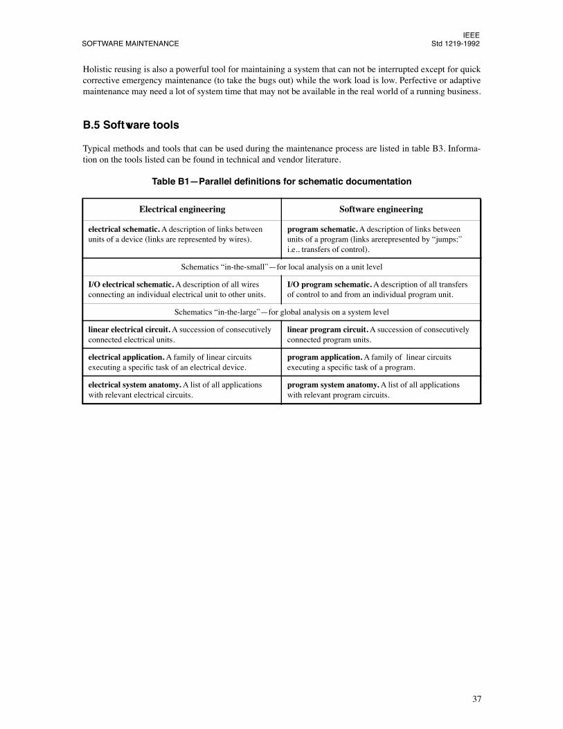
IEEESOFTWARE MAINTENANCE Std 1219-1992
37
Holistic reusing is also a powerful tool for maintaining a system that can not be interrupted except for quickcorrective emergency maintenance (to take the bugs out) while the work load is low. Perfective or adaptivemaintenance may need a lot of system time that may not be available in the real world of a running business.
B.5 Software tools
Typical methods and tools that can be used during the maintenance process are listed in table B3. Informa-tion on the tools listed can be found in technical and vendor literature.
Table B1ÑParallel deÞnitions for schematic documentation
Electrical engineering Software engineering
electrical schematic.
A description of links between units of a device (links are represented by wires).
program schematic.
A description of links between units of a program (links arerepresented by Òjumps;Ó i.e., transfers of control).
Schematics Òin-the-smallÓÑfor local analysis on a unit level
I/O electrical schematic.
A description of all wires connecting an individual electrical unit to other units.
I/O program schematic.
A description of all transfers of control to and from an individual program unit.
Schematics Òin-the-largeÓÑfor global analysis on a system level
linear electrical circuit.
A succession of consecutively connected electrical units.
linear program circuit.
A succession of consecutively connected program units.
electrical application.
A family of linear circuits executing a speciÞc task of an electrical device.
program application.
A family of linear circuits executing a speciÞc task of a program.
electrical system anatomy.
A list of all applications with relevant electrical circuits.
program system anatomy.
A list of all applications with relevant program circuits.
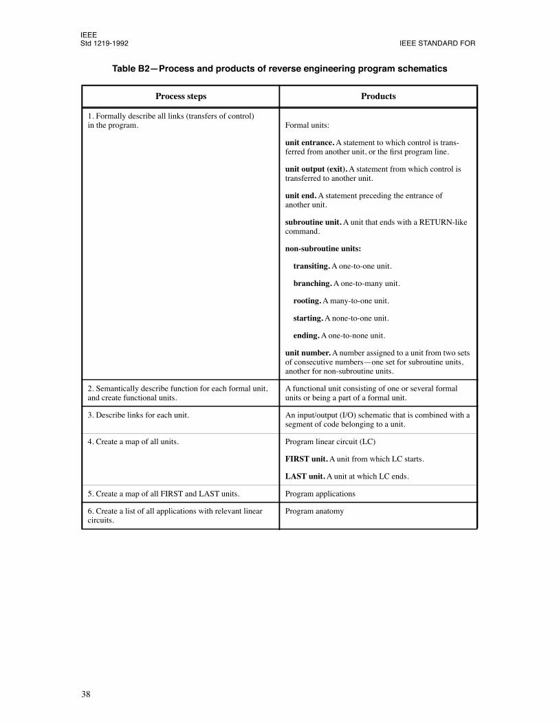
IEEEStd 1219-1992 IEEE STANDARD FOR
38
Table B2ÑProcess and products of reverse engineering program schematics
Process steps Products
1. Formally describe all links (transfers of control) in the program. Formal units:
unit entrance.
A statement to which control is trans-ferred from another unit, or the Þrst program line.
unit output (exit).
A statement from which control is transferred to another unit.
unit end.
A statement preceding the entrance of another unit.
subroutine unit.
A unit that ends with a RETURN-like command.
non-subroutine units:
transiting.
A one-to-one unit.
branching.
A one-to-many unit.
rooting.
A many-to-one unit.
starting.
A none-to-one unit.
ending.
A one-to-none unit.
unit number.
A number assigned to a unit from two sets of consecutive numbersÑone set for subroutine units, another for non-subroutine units.
2. Semantically describe function for each formal unit, and create functional units.
A functional unit consisting of one or several formal units or being a part of a formal unit.
3. Describe links for each unit. An input/output (I/O) schematic that is combined with a segment of code belonging to a unit.
4. Create a map of all units. Program linear circuit (LC)
FIRST unit.
A unit from which LC starts.
LAST unit.
A unit at which LC ends.
5. Create a map of all FIRST and LAST units. Program applications
6. Create a list of all applications with relevant linearcircuits.
Program anatomy
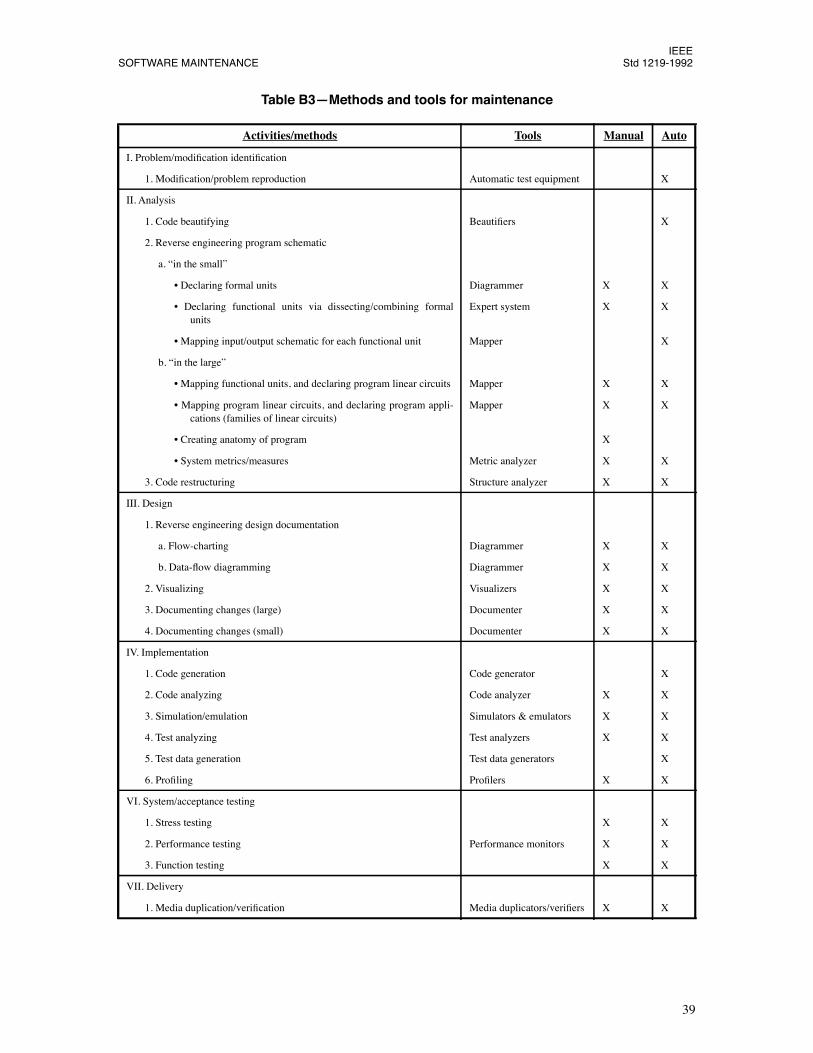
IEEESOFTWARE MAINTENANCE Std 1219-1992
39
Table B3ÑMethods and tools for maintenance
Activities/methods Tools Manual Auto
I. Problem/modiÞcation identiÞcation
1. ModiÞcation/problem reproduction Automatic test equipment X
II. Analysis
1. Code beautifying BeautiÞers X
2. Reverse engineering program schematic
a. Òin the smallÓ
¥ Declaring formal units Diagrammer X X
¥ Declaring functional units via dissecting/combining formalunits
Expert system X X
¥ Mapping input/output schematic for each functional unit Mapper X
b. Òin the largeÓ
¥ Mapping functional units, and declaring program linear circuits Mapper X X
¥ Mapping program linear circuits, and declaring program appli-cations (families of linear circuits)
Mapper X X
¥ Creating anatomy of program X
¥ System metrics/measures Metric analyzer X X
3. Code restructuring Structure analyzer X X
III. Design
1. Reverse engineering design documentation
a. Flow-charting Diagrammer X X
b. Data-ßow diagramming Diagrammer X X
2. Visualizing Visualizers X X
3. Documenting changes (large) Documenter X X
4. Documenting changes (small) Documenter X X
IV. Implementation
1. Code generation Code generator X
2. Code analyzing Code analyzer X X
3. Simulation/emulation Simulators & emulators X X
4. Test analyzing Test analyzers X X
5. Test data generation Test data generators X
6. ProÞling ProÞlers X X
VI. System/acceptance testing
1. Stress testing X X
2. Performance testing Performance monitors X X
3. Function testing X X
VII. Delivery
1. Media duplication/veriÞcation Media duplicators/veriÞers X X