IEEE ROBOTICS AND AUTOMATION MAGAZINE 1 The Vanderbilt ...
18
IEEE ROBOTICS AND AUTOMATION MAGAZINE 1 The Vanderbilt Open-Source Ventilator: From Napkin Sketch to Ready to Save Lives in 3 Weeks † Joshua Gafford*, Kevin Galloway*, Scott Webster, Max Emerson, Katherine Riojas, Dominick Ropella, Andrew Tumen, Fabien Maldonado, Matthew Bacchetta, Eric Barth, S. Duke Herrell, and Robert J. Webster III Abstract—The COVID-19 crisis has placed enormous strain on global healthcare due to the sudden and exorbitant caseload burdens, compounded by insufficient access to the requisite supplies and equipment necessary to treat patients. Most notably, critical shortages of mechanical ventilators, which are essential for oxygenating patients who cannot breathe on their own, have forced physicians to make difficult decisions between who will and will not receive treatment, especially in resource-limited communities. In this article, we describe the efforts undertaken by a consortium of engineers, roboticists, and clinicians from Vanderbilt University to develop an easily-reproducible mechan- ical ventilator out of core components that can be sourced locally, inexpensively, and en masse. Index Terms—COVID-19, Mechanical Ventilator, Volume- Controlled Ventilation THE COVID-19 PANDEMIC C OVID-19, caused by the novel human coronavirus, is a severe acute respiratory disease that has wreaked havoc on global public health with more than 14.7 million confirmed cases and 611,000 deaths worldwide as of the summer of 2020 [1], with 3.9 million cases and over 141,000 lives lost in the USA as of this writing [1]. Patients presenting with COVID-19 can develop severe acute respiratory distress syndrome (ARDS) [2], [3], which is characterized by low respiratory compliance and life- threatening impairment of pulmonary gas exchange [4], [5]. Approximately 20% of admitted COVID-19 patients require respiratory assistance from a mechanical ventilator to achieve adequate oxygenation [6]. The resource-intensive therapeutic requirements posed by COVID-19, coupled with the sudden and exorbitant caseload onset, have overburdened healthcare infrastructures across the globe due to dwindling supplies of the personal protective equipment (PPE) and devices (e.g. mechanical ventilators) necessary to protect frontline workers and treat patients with the disease [7]. Insufficient access to clinically-approved ventilation systems has forced physicians to make particularly difficult triage decisions, including modi- fication or even discontinuation of care for patients for whom † : Pre-print accepted for publication *: These authors contributed equally to this work J. Gafford, K. Galloway, M. Emerson, K. Riojas, D. Ropella, E. Barth, and R. Webster are with the Department of Mechanical Engineering, Vanderbilt University, Nashville, TN 37212. A. Tumen, F. Maldonado, M. Bacchetta, and S. Duke Herrell are with Vanderbilt University Medical Center, Nashville, TN 37212. S. Webster is with Virtuoso Surgical, Nashville, TN 37205 Tidal Volume Adjustment Knob User Interface Quick-Release Handle Ambu Bag Receptacle Pressure-Sensing Single-Limb Circuit Protective Cover 12V Power Supply Fig. 1: The Vanderbilt Open-Source Ventilator, version 4.0. The device is designed to compress a standard Ambu bag which is a widely available hand- squeezed device used to provide breathing support when transporting patients. The design features a car windshield wiper motor, Arduino-based control, and the valves and sensors needed to effectively and safely provide mechanical ventilation to COVID-19 patients. the outcome is bleak, in an effort to free up ventilators for those with more favorable prognoses [8]. Ventilator Shortages Galvanize Grassroots Innovation Recognizing these critical supply shortfalls, many commu- nities across the globe have banded together to bootstrap ad hoc solutions in an effort to bridge the supply gap. These efforts range from breweries and alcohol distilleries bottling hand sanitizer instead of beer and whiskey [9], to large automotive (General Motors [10], Tesla [11]) and aerospace (Virgin Orbit [12], SpaceX [13], NASA [14]) companies retrofitting and re-tooling entire factories to mass manufacture mechanical ventilators and requisite components at scale. A particularly inspiring example of grassroots ingenuity in the fight against COVID-19 comes from the engineering and ‘maker’ communities who have mobilized to develop custom, open-source designs for mechanical ventilators that can be rapidly manufactured with fairly simple processes and easily- sourced components. These concepts range from mechatronic systems designed to compress clinically-approved bag-valve masks (Ambu bags) at digitally-programmable rates [15]–[17], to pneumatic systems that deliver ventilation directly through digitally-controlled valves [18], to hybrid systems which use a pressurized chamber to compress an Ambu-bag [19]. To list all of the open-source designs would require a separate article by itself, so we encourage the reader to consult [20] for a more complete picture of the open-source ventilator landscape. 1070-9932/21©2021IEEE
Transcript of IEEE ROBOTICS AND AUTOMATION MAGAZINE 1 The Vanderbilt ...

IEEE ROBOTICS AND AUTOMATION MAGAZINE 1
The Vanderbilt Open-Source Ventilator: From
Napkin Sketch to Ready to Save Lives in 3 Weeks†
Joshua Gafford*, Kevin Galloway*, Scott Webster, Max Emerson, Katherine Riojas, Dominick Ropella, Andrew
Tumen, Fabien Maldonado, Matthew Bacchetta, Eric Barth, S. Duke Herrell, and Robert J. Webster III
Abstract—The COVID-19 crisis has placed enormous strainon global healthcare due to the sudden and exorbitant caseloadburdens, compounded by insufficient access to the requisitesupplies and equipment necessary to treat patients. Most notably,critical shortages of mechanical ventilators, which are essentialfor oxygenating patients who cannot breathe on their own, haveforced physicians to make difficult decisions between who willand will not receive treatment, especially in resource-limitedcommunities. In this article, we describe the efforts undertakenby a consortium of engineers, roboticists, and clinicians fromVanderbilt University to develop an easily-reproducible mechan-ical ventilator out of core components that can be sourced locally,inexpensively, and en masse.
Index Terms—COVID-19, Mechanical Ventilator, Volume-Controlled Ventilation
THE COVID-19 PANDEMIC
COVID-19, caused by the novel human coronavirus, is a
severe acute respiratory disease that has wreaked havoc
on global public health with more than 14.7 million confirmed
cases and 611,000 deaths worldwide as of the summer of 2020
[1], with 3.9 million cases and over 141,000 lives lost in the
USA as of this writing [1].
Patients presenting with COVID-19 can develop severe
acute respiratory distress syndrome (ARDS) [2], [3], which
is characterized by low respiratory compliance and life-
threatening impairment of pulmonary gas exchange [4], [5].
Approximately 20% of admitted COVID-19 patients require
respiratory assistance from a mechanical ventilator to achieve
adequate oxygenation [6]. The resource-intensive therapeutic
requirements posed by COVID-19, coupled with the sudden
and exorbitant caseload onset, have overburdened healthcare
infrastructures across the globe due to dwindling supplies of
the personal protective equipment (PPE) and devices (e.g.
mechanical ventilators) necessary to protect frontline workers
and treat patients with the disease [7]. Insufficient access to
clinically-approved ventilation systems has forced physicians
to make particularly difficult triage decisions, including modi-
fication or even discontinuation of care for patients for whom
†: Pre-print accepted for publication*: These authors contributed equally to this workJ. Gafford, K. Galloway, M. Emerson, K. Riojas, D. Ropella, E. Barth, and
R. Webster are with the Department of Mechanical Engineering, VanderbiltUniversity, Nashville, TN 37212.
A. Tumen, F. Maldonado, M. Bacchetta, and S. Duke Herrell are withVanderbilt University Medical Center, Nashville, TN 37212.
S. Webster is with Virtuoso Surgical, Nashville, TN 37205
Tidal VolumeAdjustment Knob
UserInterface
Quick-Release Handle
Ambu BagReceptacle
Pressure-SensingSingle-Limb
Circuit
Protective Cover
12V PowerSupply
Fig. 1: The Vanderbilt Open-Source Ventilator, version 4.0. The device isdesigned to compress a standard Ambu bag which is a widely available hand-squeezed device used to provide breathing support when transporting patients.The design features a car windshield wiper motor, Arduino-based control, andthe valves and sensors needed to effectively and safely provide mechanicalventilation to COVID-19 patients.
the outcome is bleak, in an effort to free up ventilators for
those with more favorable prognoses [8].
Ventilator Shortages Galvanize Grassroots Innovation
Recognizing these critical supply shortfalls, many commu-
nities across the globe have banded together to bootstrap ad
hoc solutions in an effort to bridge the supply gap. These
efforts range from breweries and alcohol distilleries bottling
hand sanitizer instead of beer and whiskey [9], to large
automotive (General Motors [10], Tesla [11]) and aerospace
(Virgin Orbit [12], SpaceX [13], NASA [14]) companies
retrofitting and re-tooling entire factories to mass manufacture
mechanical ventilators and requisite components at scale. A
particularly inspiring example of grassroots ingenuity in the
fight against COVID-19 comes from the engineering and
‘maker’ communities who have mobilized to develop custom,
open-source designs for mechanical ventilators that can be
rapidly manufactured with fairly simple processes and easily-
sourced components. These concepts range from mechatronic
systems designed to compress clinically-approved bag-valve
masks (Ambu bags) at digitally-programmable rates [15]–[17],
to pneumatic systems that deliver ventilation directly through
digitally-controlled valves [18], to hybrid systems which use
a pressurized chamber to compress an Ambu-bag [19]. To list
all of the open-source designs would require a separate article
by itself, so we encourage the reader to consult [20] for a more
complete picture of the open-source ventilator landscape.1070-9932/21©2021IEEE

IEEE ROBOTICS AND AUTOMATION MAGAZINE 2
In this article, we describe the work done by a team of
engineers, roboticists, and clinicians from Vanderbilt Univer-
sity, beginning in late March 2020, to develop an easily-
reproducible mechanical ventilator out of core components
that can be sourced locally, inexpensively, and en masse. We
detail the 3-week process that took us from initial napkin
sketches to a validated prototype and associated regulatory
submission, and provide design details and experimental val-
idation results that demonstrate the therapeutic efficacy of
the proposed design. This process resulted in an open-source
design that is set apart from other solutions by its manufac-
turing simplicity and reliance on components that are either
readily available locally or ubiquitous enough that they could
be sourced quickly even in the face of pandemic-induced
shortages and supply chain disruptions. As a supplement to
this archival publication, all design files, parts lists, software,
and testing results are made freely available in Supporting
Information documents, with the idea being that the design can
be rapidly built locally, wherever it is needed in the world, by
anyone with basic woodworking, soldering, and programming
skills.
The Vanderbilt Open-Source Ventilator (VOV)
The Vanderbilt Open-Source Ventilator (VOV) is a volume-
controlled, intubation-style ventilator (see Fig. 1). We took
this device from napkin sketch to a prototype in three weeks
which, after a successful animal study, doctors deemed able to
save a life. Over the following three weeks, we manufactured
100 units and submitted documentation to the FDA for Emer-
gency Use Authorization (EUA) clearance. Throughout this
whirlwind process, we undertook multiple design iterations,
informed by continuous clinical input, literature review, and
experimental testing, enabling us to converge on a design
that is low-cost, easily manufactured, and potentially life-
saving. Our device implements a simple, inexpensive design;
it is largely constructed from plywood, and we did away
with expensive, specialized DC/stepper motors and optical
encoders, instead relying on widely available windshield-
wiper motors and a simple reciprocating transmission design
based around a scotch-yoke mechanism and drawer glides.
The purpose of the device is to mechanically compress an
Ambu bag, a widely available medical device that is normally
squeezed by hand to transport patients to the hospital or
within the hospital when they are having difficulty breathing
on their own. By leveraging medical Ambu bags and requisite
ventilator/endotracheal (ET) tubing, the VOV is directly com-
patible with many standard oxygenation and humidification
sources, and the only components that come into contact with
the patient’s airway are clinically-approved and disposable or
otherwise subject to rigorous reprocessing protocols. We added
Arduino-based control electronics which, when combined with
mechanical inputs, enables physicians to set the volume of
air delivered each breath (called the tidal volume (TV)), the
respiratory rate in breaths-per-minute (BPM), the amount of
the breathing duty cycle devoted to inspiration vs. expiration
(i.e. the I/E ratio), and the pressure thresholds at which alarms
will sound during operation (designed in accordance with ISO
60601).
Experimental validation in both calibrated mechanical test
lungs and live animals has demonstrated that the VOV is capa-
ble of delivering consistent, repeatable, and reliable respiratory
therapy under variable loading conditions.
VOV DEVELOPMENT PROCESS
The development timeline of the Vanderbilt Open-Source
Ventilator is shown in Fig. 2.
Rallying Cry and Rapid Prototype Iteration
The project began in earnest on March 21, 2020, when
physicians at Vanderbilt University Medical Center deemed
the risk of severe local ventilator shortages high enough that
all efforts that could be brought to bear on the problem should
be made. Sensing the urgency in their clinical colleagues,
the engineering team quickly came together, consisting of
faculty and graduate students with all of the skillsets required
to quickly build a mechanical ventilator prototype. Within a
matter of hours after this clinical call-to-action, a napkin sketch
made by one of the engineers (Fig. 2(a)) was converted into
a first prototype (Fig. 2(b)) that demonstrated the concept of
using a motor-driven mechanism to compress an Ambu bag at
a consistent rate to deliver mechanical ventilation. The need
for accurate, continuous TV adjustment led to the development
of Version 2.0 on March 24th (Fig. 2(c)), which implemented
the scotch-yoke mechanism (SYM) that would become the
preferred transmission mechanism of the design (described in
more detail in the “Mechanical Design” section). In v2.0, the
TV is adjusted by physically sliding the SYM to increase or
reduce the compression of the Ambu bag on a single stroke.
This TV adjustment mechanism was further improved in v3.0
(Fig. 2(d)) with a manually-actuated leadscrew.
At the time, the system was powered by an off-board
adjustable lab power supply, meaning that only the BPM
could be crudely adjusted by changing the voltage setting
of the supply. Realizing the need for more accurate control,
sensors, and safety features, an embedded system (centered
around an Arduino Uno) and an associated user interface
(UI) was developed in parallel (Fig. 2(e)) that would enable
digital configuration and control of the ventilation profile,
as well as the ability to report anomalous events to the
caregiver through an ISO 60601-standardized alarm profile. As
the design progressed, extensive manufacturing and assembly
instructions were created (Fig. 2(f)) that would enable others
to manufacture the VOV, which would be continually updated
throughout the remainder of the project to reflect all design
modifications. A complete Institutional Animal Care and Use
Committee (IACUC) protocol was drafted and approved by
Vanderbilt in 2 days, enabling us to move forward with animal
experiments.
Concept Refinement and Testing
The integration of the UI/embedded controller with v3.0 led
to the creation of v3.1 (Fig. 2(g)) on April 2nd, which would
be the first unit tested in an in vivo setting on the next day.
At our first live swine experiment on April 3rd, we observed

IEEE ROBOTICS AND AUTOMATION MAGAZINE 3
Mar 2
1: VOV project
begins
Mar 2
2: First
conceptu
al sketches
Mar 2
3: First
prototype constr
ucted (v1.0)
Mar 2
4: Second pro
totype constructed (v
2.0)
Mar 2
5: Firs
t ex-vivo te
sts in
pig lung
Mar 2
9: Embedded contro
ller d
esigned
Apr 3: First live animal study
Apr 1: I
ACUC protocol approved
Mar 23: v1.0
Mar. 28: v3.0
Mar 22: sketches
Mar 24: v2.0
Apr 5: Inclusion of Single-Limb Circuit
Apr 8: Second live animal study
Apr 9: Final prototype (v4.0)
Apr 2: Electronics mounted (v3.1)
Apr 10: Risk
/Haza
rd Analysis
complet
e
Apr 12: M
anufacturin
g of 100 units
commences
Apr 23: Initia
l FDA E
UA submiss
ion
Apr 22: C
onfirmatory hist
ology resu
lts fr
om second anim
al study
Apr 2: v3.1
May 1: S
ubstantia
l vari
ability te
sting
Apr 11: Long-term cyclic testing (unit running continuously)
Mar. 29: Controller
Apr 8: Live Animal Study
Apr 9: v4.0
Apr 17: Batch fabrication
Apr 17: F
irst 2
0 units fu
lly asse
mbled/te
sted
Apr 27: 100 m
echanica
l asse
mblies c
omplete
Mar 3
1: Fabrica
tion in
structio
Mar
Apr
Apr May
(a) (b) (c)
(d)
(g)
(h)
(i)
(j)
D e v e l o p me n
t
R
ef i n e m e n t
S c a l e - U p
Mar 2
8: Third
prototype constr
ucted (v3.0)
Mar 2
6: Niss
an donates initia
l batc
h of motors
Mar 3
0: IACUC protocol s
ubmitted
Apr 6: Alarms and safety features implemented
Fig. 2: Development timeline of the Vanderbilt Open-Source Ventilator, where (a)-(j) denote key developmental landmarks.
insufficient gas exchange from our device resulting in the
animal breathing out of synchronization with our ventilator.
This was found to be due to the existence of substantial
dead space in the ventilation circuit (specifics of which are
provided in the “In Vivo and In Vitro Testing” section).
To rectify this, we integrated a pressure-sensing single-limb
circuit into the design which places the valves at the patient’s
mouth rather than remotely at the outlet of the Ambu bag. A
second 4-hour live swine experiment (Fig. 2(h)) was conducted
five days later, in which the device worked flawlessly. After
the second swine study, the VOV prototype was given the
‘thumbs-up’ from clinical collaborators as a system that they
would be comfortable using to support COVID-19 patients if
no clinically-approved ventilators were available. A thorough
FDA risk analysis was then performed, and informed some de-
sign modifications to enhance safety, creating v4.0 (Fig. 2(i)),
which we describe in the remainder of this article.
Design Lock-In and Manufacturing Scale-Up
Immediately following approval from our clinical collabo-
rators, we began working with several local Nashville com-
panies to ramp up production. Part kits and assembly in-
structions were distributed to a volunteer workforce consisting
of Vanderbilt graduate students, faculty, and staff, as well
as local unaffiliated ‘makers’ and tech enthusiasts in the
greater Nashville area. One hundred windshield wiper motor
assemblies were generously donated by Nissan Smyrna, a
local automobile assembly plant. A local marketing agency
(Abel+McCallister+Abel, Nashville, TN) volunteered their
facilities and personnel to CNC-route all of the plywood
components, which were subsequently assembled by a group
of volunteers from two local makerspaces, Fort Houston and
Make Nashville. Electronic control boxes were wired and as-
sembled by a group of Vanderbilt University graduate students.
All manufacturing and assembly instructions were communi-
cated to volunteers using the documents made available in
the Supplementary Information. Over the course of the next
two weeks, we assembled the mechanical frames for 100 units
(Fig. 2(j)). By April 17, twenty of these mechanical units
were outfitted with fully-wired control boxes for immediate
use, with parts-on-hand for 80 more if needed. An EUA
application was submitted to the FDA on April 23rd based on
IEEE ROBOTICS AND AUTOMATION MAGAZINE 4
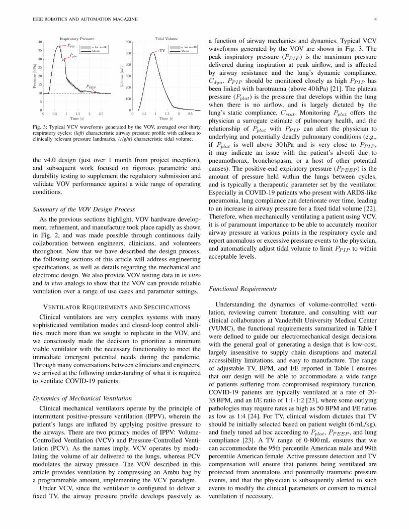
PPIP
Pplat
PPEEP
TV
Fig. 3: Typical VCV waveforms generated by the VOV, averaged over thirtyrespiratory cycles: (left) characteristic airway pressure profile with callouts toclinically relevant pressure landmarks, (right) characteristic tidal volume.
the v4.0 design (just over 1 month from project inception),
and subsequent work focused on rigorous parametric and
durability testing to supplement the regulatory submission and
validate VOV performance against a wide range of operating
conditions.
Summary of the VOV Design Process
As the previous sections highlight, VOV hardware develop-
ment, refinement, and manufacture took place rapidly as shown
in Fig. 2, and was made possible through continuous daily
collaboration between engineers, clinicians, and volunteers
throughout. Now that we have described the design process,
the following sections of this article will address engineering
specifications, as well as details regarding the mechanical and
electronic design. We also provide VOV testing data in in vitro
and in vivo analogs to show that the VOV can provide reliable
ventilation over a range of use cases and parameter settings.
VENTILATOR REQUIREMENTS AND SPECIFICATIONS
Clinical ventilators are very complex systems with many
sophisticated ventilation modes and closed-loop control abili-
ties, much more than we sought to replicate in the VOV, and
we consciously made the decision to prioritize a minimum
viable ventilator with the necessary functionality to meet the
immediate emergent potential needs during the pandemic.
Through many conversations between clinicians and engineers,
we arrived at the following understanding of what it is required
to ventilate COVID-19 patients.
Dynamics of Mechanical Ventilation
Clinical mechanical ventilators operate by the principle of
intermittent positive-pressure ventilation (IPPV), wherein the
patient’s lungs are inflated by applying positive pressure to
the airways. There are two primary modes of IPPV: Volume-
Controlled Ventilation (VCV) and Pressure-Controlled Venti-
lation (PCV). As the names imply, VCV operates by modu-
lating the volume of air delivered to the lungs, whereas PCV
modulates the airway pressure. The VOV described in this
article provides ventilation by compressing an Ambu bag by
a programmable amount, implementing the VCV paradigm.
Under VCV, since the ventilator is configured to deliver a
fixed TV, the airway pressure profile develops passively as
a function of airway mechanics and dynamics. Typical VCV
waveforms generated by the VOV are shown in Fig. 3. The
peak inspiratory pressure (PPIP ) is the maximum pressure
delivered during inspiration at peak airflow, and is affected
by airway resistance and the lung’s dynamic compliance,
Cdyn. PPIP should be monitored closely as high PPIP has
been linked with barotrauma (above 40 hPa) [21]. The plateau
pressure (Pplat) is the pressure that develops within the lung
when there is no airflow, and is largely dictated by the
lung’s static compliance, Cstat. Monitoring Pplat offers the
physician a surrogate estimate of pulmonary health, and the
relationship of Pplat with PPIP can alert the physician to
underlying and potentially deadly pulmonary conditions (e.g.,
if Pplat is well above 30 hPa and is very close to PPIP ,
it may indicate an issue with the patient’s alveoli due to
pneumothorax, bronchospasm, or a host of other potential
causes). The positive-end expiratory pressure (PPEEP ) is the
amount of pressure held within the lungs between cycles,
and is typically a therapeutic parameter set by the ventilator.
Especially in COVID-19 patients who present with ARDS-like
pneumonia, lung compliance can deteriorate over time, leading
to an increase in airway pressure for a fixed tidal volume [22].
Therefore, when mechanically ventilating a patient using VCV,
it is of paramount importance to be able to accurately monitor
airway pressure at various points in the respiratory cycle and
report anomalous or excessive pressure events to the physician,
and automatically adjust tidal volume to limit PPIP to within
acceptable levels.
Functional Requirements
Understanding the dynamics of volume-controlled venti-
lation, reviewing current literature, and consulting with our
clinical collaborators at Vanderbilt University Medical Center
(VUMC), the functional requirements summarized in Table I
were defined to guide our electromechanical design decisions
with the general goal of generating a design that is low-cost,
largely insensitive to supply chain disruptions and material
accessibility limitations, and easy to manufacture. The range
of adjustable TV, BPM, and I/E reported in Table I ensures
that our design will be able to accommodate a wide range
of patients suffering from compromised respiratory function.
COVID-19 patients are typically ventilated at a rate of 20-
35 BPM, and an I/E ratio of 1:1-1:2 [23], where some outlying
pathologies may require rates as high as 50 BPM and I/E ratios
as low as 1:4 [24]. For TV, clinical wisdom dictates that TV
should be initially selected based on patient weight (6 mL/kg),
and finely tuned ad hoc according to Pplat, PPEEP , and lung
compliance [23]. A TV range of 0-800 mL ensures that we
can accommodate the 95th percentile American male and 99th
percentile American female. Active pressure detection and TV
compensation will ensure that patients being ventilated are
protected from anomalous and potentially traumatic pressure
events, and that the physician is subsequently alerted to such
events to modify the clinical parameters or convert to manual
ventilation if necessary.

IEEE ROBOTICS AND AUTOMATION MAGAZINE 5
k
c
WiperMotor
SlidingYoke
PinCrankArm
AmbuBag
lc
x
Slot
x[m
m]
[Nm
]
[rad]
(b) (c)
Pin
SlidingYoke
WiperMotor
CrankArm
Drawer Glides
(a)
x
SYMGround
TVAdjustKnob
TVAdjustScrew
SlidingSYM
Assembly
InspirationExpiration InspirationExpiration
ThrustSurface
SYMDisengage
HandleInspirationExpiration InspirationExpiration
Stationary BaseLinear Guide
2
Scotch-Yoke Mechanism
Leadscrew-Driven Tidal Volume Adjustment
(e) (f) (g)
1
2
SlidingSYM
Assembly
SYMDisengage
Handle
(h) (i) (j)
ManualTake-over
Quick-Disengage for Manual Take-over
Stationary Base TV Adjust Screw
CCW CW
DisengageEndstop
1
Jamnuts
Fig. 4: VOV Mechanical Design: (a) SYM implemented on the VOV (where the sliding yoke is removed on the left to show the wiper motor and crank arm),(b) lumped-parameter model of SYM compressing an Ambu bag with airway compliance and resistance modeled as a spring and damper, respectively, (c)
characteristic steady-state waveforms of crank angle φ vs. compression distance x (top) and motor torque τ (bottom), (e) leadscrew-driven TV adjustmentmechanism (enclosure removed for clarity), (f) counter-clockwise rotation of the knob advances the SYM towards the Ambu bag receptacle, increasing TVdelivery per stroke, (g) clockwise rotation retracts the SYM, reducing the TV delivery per stroke, (h) emergency mechanical disengage (enclosure removed forclarity), (i) pulling the disengage handle removes the leadscrew thrust surface, and (j) pulling the TV leadscrew backwards retracts the SYM sub-assembly,opening up the Ambu bag receptacle for manual removal/take-over.
Parameter Value
Tidal Volume (TV) 0-800 [mL] (Adjustable)
Max TV Deviation (long-term) 35%
Respiratory Rate 5-55 [BPM] (Adjustable)
BPM Repeatability (over 1 minute) ±1 [BPM]
I:E Ratio 1:1-1:4 (Adjustable)
Continuous Operation >14 [days]
Maximum Deliverable PPIP >40 [hPa]
PPEEP 0-25 [hPa] (Adjustable)
Barotrauma Pressure Limiting? Yes
Over/Under-Pressure Reporting? Yes (Adjustable)
TABLE I: List of VOV Functional Requirements
MECHANICAL DESIGN
We approached the VCV design challenge by first identi-
fying the actuator and structural materials given the general
constraints of availability, cost, and manufacturability. We
selected the windshield wiper motor for its low cost, global
availability, and ease of sourcing from auto manufacturers to
junk yards. Furthermore, the worm gear mechanism inside
the motor is designed to generate large forces at a range
of speeds under extreme conditions from sub-freezing to
extremely hot (>37 C◦) environments. These features make
windshield wiper motors excellent candidates for applications
that require reciprocating, low-to-medium speed actuation for
millions of cycles.
For the structural material, plywood was selected also for
its availability and the relatively simple and inexpensive tools
required to manufacture components. Cabinet makers, wood
workers, and many hobbyists have the tools and know-how to
make all the mechanical parts.
Scotch Yoke Mechanism
Given these materials and constraints, the scotch yoke
mechanism offers a simple, relatively low component-count
and low fabrication-precision-threshold solution to replicate
the squeezing motion of the human hand. The SYM is a
reciprocating motion mechanism that converts rotary motion
into linear motion, as shown in Fig. 4(a)-(b). The SYM
transmission couples the pin on a rotating crank arm directly
to a sliding yoke with slot that engages the pin. The linear
travel of the sliding yoke in this design is constrained by
IEEE ROBOTICS AND AUTOMATION MAGAZINE 6
DISABLEDentry: reset idle timer
do: button listener
PROGRAMMING
do: read pots, updateparameters
exit: save to EEPROM
entry: load parametersfrom EEPROM
PPPROG
Standby Mode
INSPIRATION
exit: update /set vi
entry: report PPEEP, get expiration time te,a, reset inspiration timer
BARO AVOIDentry: report Pmax
INSP HOLD
exit: report PPIP
entry: read PPIP
do: report Pplat
P>Pbaro
INSP LIM
ENABLE
Ventilation Mode
EXPIRATION
exit: set ve
entry: report PPIP, get inspiration time ti,a, reset expiration timer
Homing Mode
EXP HOLD
exit: set ve
entry: set hold timer thold
EXP LIM & te,d>tdb
EXP LIM& te,d<tdb
thold>tdb-te,aPP
EXP LIM
PPIP>Pmax
PPIP<Pmin
PPIP<Pdis
P>Pbaro
ti,a>ttimeout
tidle>ttimeout
ALARM MANAGERAlarmStates{ BAROTRAUMA, MAX PRESSURE, MIN PRESSURE, DISCONNECT, MOTOR TIMEOUT, IDLE TIMEOUT};
Sequential (Loop State Transition)
Parallel (Outside of Loop)
PROGRAMMING
do: read pots, updateparameters
exit: save to EEPROM
entry: load parametersfrom EEPROM
PROG PROG
PWM1, PWM2
SDA/SCL
M+, M-
(2x) Analog In
(4x)Digital In
Fault1, Fault2
On-Board Controller
SYM
PWMb
(1x) Digital Out
Control Switches
and Buttons
Programming
Potentiometer
16 x 2 Feedback
LCD Screen
Alarm LED
Alarm Buzzer
BTS7960B
Dual Half-Bridge
Motor Driver
Windshield
Wiper Motor
Limit
Switches
Pressure
Sensor
(2X) Digital In
(1X) Analog In
(a) (b)
(c)
Atmega328
MCU
Power
Enable PP Prog Param Tuning
Alarm
ENABLE
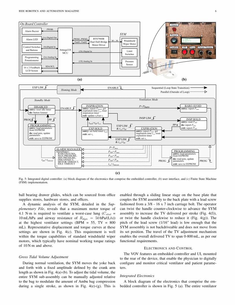
Fig. 5: Integrated digital controller: (a) block diagram of the electronics that comprise the embedded controller, (b) user interface, and (c) Finite State Machine(FSM) implementation.
ball bearing drawer glides, which can be sourced from office
supplies stores, hardware stores, and offices.
A dynamic analysis of the SYM, detailed in the Sup-
plementary File, reveals that a maximum motor torque of
4.1 N·m is required to ventilate a worst-case lung (Cstat =
10 mL/hPa and airway resistance of Rdyn = 50 hPa/(L/s))
at the highest ventilator settings (BPM = 55, TV = 800
mL). Representative displacement and torque curves at these
settings are shown in Fig. 4(c). This requirement is well
within the torque capabilities of standard windshield wiper
motors, which typically have nominal working torque ratings
of 10 N·m and above.
Gross Tidal Volume Adjustment
During normal ventilation, the SYM moves the yoke back
and forth with a fixed amplitude defined by the crank arm
length as shown in Fig. 4(a)-(b). To adjust the tidal volume, the
entire SYM sub-assembly can be manually adjusted relative
to the bag to modulate the amount of Ambu bag compression
during a single stroke, as shown in Fig. 4(e)-(g). This is
enabled through a sliding linear stage on the base plate that
couples the SYM assembly to the back plate with a lead screw
fashioned from a 3/8 - 16 x 7 inch carriage bolt. The operator
can twist the handle counter-clockwise to advance the SYM
assembly to increase the TV delivered per stroke (Fig. 4(f)),
or twist the handle clockwise to reduce it (Fig. 4(g)). The
pitch of the lead screw (1/16” lead) is low enough that the
SYM asssembly is not backdriveable and does not move from
its set position. The travel of the TV adjustment mechanism
enables the overall delivered TV to span 0-800 mL, as per our
functional requirements.
ELECTRONICS AND CONTROL
The VOV features an embedded controller and UI, mounted
to the rear of the device, that enable the physician to digitally
configure and monitor critical ventilator and patient parame-
ters.
Integrated Electronics
A block diagram of the electronics that comprise the em-
bedded controller is shown in Fig. 5 (a). The entire ventilator

IEEE ROBOTICS AND AUTOMATION MAGAZINE 7
Plim
20.0 12.5 9.00 7.00Static Compliance [mL/hPa]: 5.50
Fig. 6: Automatic tidal volume modulation to limit peak inspiratory pressure(where shaded gradients indicate the artificially-induced lung compliance):(top) airway pressure vs. time, (middle) flow rate vs. time, (bottom) tidalvolume vs. time.
system (motor, sensors, and on-board controller) is powered
by a 12 VDC, 5 A, ISO60601-compliant power supply. The
Arduino Uno MCU (or equivalent) is responsible for executing
the integrated controller, processing sensor/user interface data,
and issuing motor commands. Various UI features (poten-
tiometers, buttons, switches, and an LCD screen) allow the
physician to interact with the ventilator and monitor the status
of both the ventilator and the patient, as shown in Fig. 5 (b).
Control Architecture
The controller is implemented in the form of a finite state
machine (FSM), illustrated in Fig. 5(c). An Alarm Manager
object keeps track of various alarm conditions outside of the
loop and reports them to the user through a combination
of flashing LED, ringing buzzer, and a message displayed
on the UI LCD. We also note that new settings may be
programmed while the ventilator is actively ventilating without
breaking the main loop, enabling the physician to modify
ventilation parameters during operation based on feedback
from the pressure-sensing single-limb circuit. Patient safety
was of paramount importance in every design decision of the
VOV, particularly in regards to barotrauma avoidance. The
VOV implements active barotrauma avoidance by modulating
the tidal volume if the inspiratory pressure exceeds pre-defined
Fig. 7: End-cycle proportional timing controller for various BPM and I/Esettings: (top) BPM vs. cycle number (commanded and actual), (middle)
I/E ratio vs. cycle number (commanded and actual), (bottom) speed scalingparameters α and β vs. cycle number.
thresholds, as shown experimentally in Fig. 6. This is detailed
in the Supplementary File, as are numerous other control-based
and mechanical-based safety solutions.
End-Cycle Proportional Timing Control Methodology
Windshield wiper motors run in open loop, so to achieve
accurate respiratory rate timing, we have implemented an end-
cycle proportional timing controller. We sense the position of
the motor at the two most important points in the respiratory
cycle (full inspiration and full expiration) with a pair of limit
switches, dead-reckon between these two points, and adjust
speeds on the next cycle as necessary to meet these respiratory
timing requirements based on the error between the desired
and actual inspiration/expiration times. The specific hardware
implementation of the end-cycle proportional timing method-
ology is available in the Supplementary File. This proportional
timing update capability is demonstrated experimentally in
Fig. 7, where the BPM and I/E ratio were increased every
50 cycles (12 BPM at 1:4 I/E, 20 BPM at 1:3 I/E, 30 BPM at
1:2 I/E, and 40 BPM at 1:1 I/E) while the VOV was actively
ventilating a test lung apparatus with a built-in compliance of
20 mL/hPa. As can be observed, the VOV is quick to converge
to the new settings (within 30% of the desired setting after a
single breath cycle), and with negligible steady-state error.

IEEE ROBOTICS AND AUTOMATION MAGAZINE 8
(c)
1
2
7
5
6
3
4
(e)
(f)
(a)
(b)
SYM and
Ambu-Bag
Pressure-
Sensing Single-
Limb Circuit
FS6122
Pressure/Flow
Sensor
Atmega328
Data
Acquisition
1 2 3
4
6 7
Vanderbilt Open-Source Ventilator Experimental Setup
Michigan
Instruments
Model 1601
Pneumatic
Electrical
Legend Host
PC
t,p,q,v
Serial Rx/Tx
Resistance
5
p
Fig. 8: In vivo and in vitro experimental setups: (a) experimental setup for the live swine study, (b)-(c) histological analysis of alveolar structure (Gomoritrichrome) at 5x (b) and 20x (c) magnification reveals maintenance of alveolar and airway structural integrity without evidence of barotrauma or atelectasis,(e) block diagram of in vitro experimental setup for parameter variability study, (f) photograph of the in vitro experimental setup.
IN VIVO AND IN VITRO TESTING
In preparation for the FDA EUA submission, the VOV has
been experimentally validated using a combination of in vitro
validation in a calibrated mechanical test lung, as well as live
animal testing using an anesthetized swine model.
In Vivo Swine Study
Two live animal studies were performed where the VOV
provided continuous ventilation to an anesthetized swine for
four hours. In the first study, as mentioned in the “VOV Devel-
opment Process” section, there was insufficient gas exchange
due to the length of the ET tubing. For a more detailed dis-
cussion of this please see “Insights from First In Vitro Swine
Study” in the Supplementary File. In the second swine study,
we corrected the problem with a pressure-sensing single-limb
circuit (Fig. 8(a)). The swine was ventilated continuously for
four hours (with average settings of 20 BPM and an I/E ratio
of 1:2) as per our approved IACUC protocol. Throughout the
course of the second experiment, the swine remained hemo-
dynamically normal, with adequate oxygenation, ventilation,
and a normal pH. Subsequent histology results revealed well-
preserved alveolar structural integrity with no evidence of
barotrauma or atelectasis (Fig. 8(b)-(c)) [25].
It is likely that humidification would be useful in future long
term (e.g. weeks) use of this ventilator with human patients.
We accomplished this successfully in our first animal study
with a standard off-the-shelf nebulizer (Aquapak, 760 mL)
hooked up to the Ambu bag input. It was determined by
our veterinary staff that this was not needed for our second
animal study because the duration was hours rather than days
or weeks.
In Vitro Parameter Variation/Durability Study
In addition to live animal tests, we also performed a series
of performance characterization and durability experiments
on a mechanical test lung, pursuant to testing standards set
forth in ISO 80601-2-80:2018(E): “Particular Requirements
for Basic Safety and Essential Performance of Ventilatory
Support Equipment for Ventilatory Insufficiency” [26]. The
tests were performed using a calibrated test lung (Model 1601,
Michigan Instruments) with adjustable compliance and linear
resistance, which was generously loaned to the project by
Volunteer State Community College, Gallatin, TN. A Siargo
FS6122 pressure/flow sensor was used to capture pressure,
flow rate and tidal volume waveform data at a sampling rate
of 200 samples/sec. The TV was calculated by numerically
integrating the flow rate data. Data were post-processed and
statistically analyzed in MATLAB. The experimental setup is
shown in Fig. 8(e)-(f).
Characteristic flow rate, airway pressure, and tidal volume
waveforms from these experiments are shown in Fig. 9. For
the purpose of brevity, we observe that cyclic variability is
very low across short (seconds) and long (hours) time scales
and is well within acceptable limits as per ISO 80601-2-
80:2018(E). The details of these experiments are presented
in the Supplementary File.
CONCLUSION
The COVID-19 pandemic has crippled healthcare infras-
tructures across the globe due to insufficient supplies of
protective, diagnostic, and therapeutic equipment. Most no-
tably, clinically-approved ventilator shortages have led to many
preventable deaths. This shortage has motivated engineering
communities to quickly mobilize and develop alternative so-
lutions that could provide a last resort for patients who face
triage. As part of this effort, the Vanderbilt Open-Source
Ventilator was developed by a team of engineers, roboticists
and clinicians to provide an alternative to patients who oth-
erwise may not have access to traditional clinical mechanical
ventilators. Manufactured from inexpensive and easy-to-source
components, the VOV and its open-source design could serve

IEEE ROBOTICS AND AUTOMATION MAGAZINE 9
Cstat [mL/hPa]
Rdyn [hPa/L/s]
TV [mL]
BPM
I:E Ratio
PPEEP [hPa]
ValueSettings
qmax [L/s]
Vmax [mL]
Pmax [hPa]
Max DevParameter
PPEEP [hPa]
70.5±1.00 6.06%
504±2.52
14.3±0.15
5.10±0.06
50
5
500
20
1:2
5
Performance Parameters
Ventilator/Lung Settings
2.15%
5.64%
5.20%
Cstat [mL/hPa]
Rdyn [hPa/L/s]
TV [mL]
BPM
I:E Ratio
PPEEP [hPa]
ValueSettings
qmax [L/s]
Vmax [mL]
Pmax [hPa]
Max DevParameter
PPEEP [hPa]
38.2±0.60 4.79%
300±2.28
47.0±0.37
9.29±0.20
10
50
300
20
1:2
10
Performance Parameters
Ventilator/Lung Settings
3.26%
3.46%
8.13%
Cstat [mL/hPa]
Rdyn [hPa/L/s]
TV [mL]
BPM
I:E Ratio
PPEEP [hPa]
ValueSettings
qmax [L/s]
Vmax [mL]
Pmax [hPa]
Parameter
PPEEP [hPa]
62.1±2.80
344±13.9
95.9±0.30
15.5±0.30
10
50
350
30
1:2
5
Performance Parameters
Ventilator/Lung Settings
66.4±0.90
353±5.60
93.1±1.50
7.90±1.10
(a) (b) (c) (d)
(e) (f) (g) (h)
(i) (j) (k) (l)
(Pre) (Post)
Fig. 9: Parameter variability testing per ISO 80601: (a)-(d) performance data and characteristic waveforms for a compliant, low-resistance airway, (e)-(h)
performance data and characteristic waveforms for a stiff, high-resistance airway, (i)-(l) performance data and characteristic waveforms at worst-case, near-maximum settings over a 24 hour period, where black denotes characteristic performance prior to the 24 hour period, and red denotes characteristic performanceafter the 24 hour period.
as a viable option for resource-constrained communities who
are severely impacted by COVID-19 or similar respiratory
viruses that may present in the future. By distributing the
design files found in the Supplementary Information to mem-
bers of the local community, we have manufactured 100
ventilators ready for immediate deployment in Nashville and
middle Tennessee, and we envision a similar deployment
model being used in other communities with access to our
design files and basic woodworking/electronics materials and
fabrication equipment. While the VOV is not intended to
replace clinically-approved ventilators, it is capable of carrying
out many critical therapeutic functions necessary to support
COVID-19 patients as substantiated through extensive in vivo
and in vitro testing (specifically designed according to testing
standards set forth in ISO 80601-2-80:2018(E) which is an
FDA-recognized standard for evaluating ventilation equipment
submitted for emergency use). It is thus ready to save lives in
the emergency event where the demand for ventilators outstrips
the supply.
ACKNOWLEDGEMENTS
We would like to formally thank our partners for making
this project possible including the Provost’s Office at Van-
derbilt University, Vanderbilt’s Office of General Counsel, the
Wond’ry, the Vanderbilt Institute for Surgery and Engineering
(VISE), the Vanderbilt University Medical Center and the
Institutional Animal Care and Use Committee (IACUC), the
MED Lab at Vanderbilt, the DCES Lab at Vanderbilt, the

IEEE ROBOTICS AND AUTOMATION MAGAZINE 10
NERD Lab at Vanderbilt, Volunteer State Community College,
Abel+McCallister+Abel, Nissan Smyrna, George P. Johnson
Experience Marketing, Fort Houston, Make Nashville and
Virtuoso Surgical.
REFERENCES
[1] E. Dong, H. Du, and L. Gardner, “An interactive web-based dashboardto track covid-19 in real time,” Lancet Infect Dis, vol. 20, pp. 533–534,2020.
[2] L. Hariri and C. C. Hardin, “Covid-19, angiogenesis, and ards endo-types,” New England Journal of Medicine, vol. 383, no. 2, pp. 182–183,2020.
[3] J. J. Marini and L. Gattinoni, “Management of COVID-19 RespiratoryDistress,” JAMA, vol. 323, no. 22, pp. 2329–2330, 06 2020.
[4] S. V. Cherian et al., “Salvage therapies for refractory hypoxemia inARDS,” Respir Med, vol. 141, pp. 150–158, 2019.
[5] T. Bein et al., “The standard of care of patients with ARDS: ventilatorysettings and rescue therapies for refractory hypoxemia,” Intensive Care
Medicine, vol. 42, no. 5, pp. 699–711, 2016.
[6] S. Richardson et al., “Presenting Characteristics, Comorbidities, andOutcomes Among 5700 Patients Hospitalized With COVID-19 in theNew York City Area,” JAMA, vol. 323, no. 20, pp. 2052–2059, 05 2020.
[7] M. L. Ranney et al., “Critical supply shortages — the need for ventilatorsand personal protective equipment during the covid-19 pandemic,” New
England Journal of Medicine, vol. 382, no. 18, p. e41, 2020.
[8] L. Rosenbaum, “Facing covid-19 in italy — ethics, logistics, andtherapeutics on the epidemic’s front line,” New England Journal of
Medicine, vol. 382, no. 20, pp. 1873–1875, 2020.
[9] E. Thomson and A. Bullied, “Production of Ethanol-Based Hand San-itizer in Breweries During the COVID-19 Crisis,” MBAA TQ, vol. 57,no. 1, pp. 47–52, 2020.
[10] S. Morrison, “Ford and GM are making tens of thousands of ventilators.It may already be too late.” 2020. [Online]. Available: https://www.vox.com/recode/2020/4/10/21209709/tesla-gm-ford-ventilators-coronavirus
[11] M. Burns, “Tesla shows how it’s building venitlators with carparts,” 2020. [Online]. Available: https://techcrunch.com/2020/04/05/tesla-shows-how-its-building-ventilators-with-car-parts/
[12] C. Gohd, “Virgin Orbit designs new ventilator as part of Virgin Group’sefforts to combat coronavirus,” 2020. [Online]. Available: https://www.space.com/virgin-orbit-designs-ventilator-to-fight-coronavirus.html
[13] K. Korosec, “SpaceX and Tesla are ‘working on’ ventilators, ElonMusk says,” 2020. [Online]. Available: https://techcrunch.com/2020/03/20/spacex-and-tesla-are-working-on-ventilators-elon-musk-says/
[14] A. Good, “NASA Develops COVID-19 Prototype Ventilator in 37Days,” 2020. [Online]. Available: https://www.jpl.nasa.gov/news/news.php?feature=7646
[15] MIT, “MIT Emergency Ventilator Project,” 2020. [Online]. Available:https://e-vent.mit.edu/
[16] D. Etherington, “Spiro Wave emergency ventilator gains FDAauthorization to address COVID-19 demand,” 2020. [Online]. Available:https://techcrunch.com
[17] University of Minnesota, “COVID-19 Ventilator,” 2020. [Online].Available: https://med.umn.edu/covid19Ventilator
[18] Stanford University, “OP-Vent: A Simple, Open-Source Ventilatorusing a Proportional Solenoid Valve,” 2020. [Online]. Available:https://op-vent.stanford.edu/
[19] University of Oxford, “OxVent,” 2020. [Online]. Available: https://oxvent.org/
[20] J. Pearce, “A review of open source ventilators for covid-19 and futurepandemics,” F1000 Research, vol. 9, no. 218, pp. 1–14, 2020.
[21] T. W. Marcy, “Barotrauma: Detection, recognition, and management,”Chest, vol. 104, no. 2, pp. 578–584, 1993.
[22] S. Sarma, “Acute respiratory distress syndrome.” BMJ clinical evidence,2010. [Online]. Available: https://www.ncbi.nlm.nih.gov/pmc/articles/PMC3217743/
[23] S. Price et al., “Respiratory management in severe acute respiratorysyndrome coronavirus 2 infection,” European Heart Journal: Acute
Cardiovascular Care, vol. 9, no. 3, pp. 229–238, 2020.
[24] E. Sembroski, D. Sanghavi, and A. Bhardwaj, “Inverse ratioventilation,” StatPearls, 2020. [Online]. Available: https://www.ncbi.nlm.nih.gov/books/NBK535395/
[25] A. Tumen et al., “Commodore open-source ventilator: Rapid develop-ment and testing in a large animal model,” ASAIO (Submitted), 2020.
[26] International Standards Organization ISO/TC 121/SC 3, “ISO 90601–2-80-2018(en) medical electrical equipment — part 2–80: Particularrequirements for basic safety and essential performance of ventilatorysupport equipment for ventilatory insufficiency.” 2018. [Online].Available: https://www.iso.org/standard/68844.html
Supplementary Material For: The Vanderbilt Open-Source
Ventilator: From Napkin Sketch to Ready to Save Lives in 3 Weeks∗
Joshua Gafford, Kevin Galloway, Scott Webster, Max Emerson, Katherine Riojas,
Dominick Ropella, Andrew Tumen, Fabien Maldonado, Matthew Bacchetta, Eric Barth,
S. Duke Herrell, and Robert J. Webster III
1 Pressure Sensing Options
As detailed in the article, three options for pressure sensing were explored: i) a U-tube water manometer, ii)a mechanical spring-based pressure sensor with LEDs for over and under pressure alarm, and iii) a MEMS-based electronic pressure transducer. We began with the U-tube water manometer because it appeared tobe a simple, ultra-low-cost, easily constructed pressure sensing concept that physicians already sometimesuse to measure airway pressure in low-resource settings. We viewed it as a positive that the device can easilybe constructed from a wide variety of inexpensive components (e.g. plastic or rubber tubing), and as such,this concept is relatively impervious to the supply chain disruptions that can occur during a pandemic. TheU-tube manometer can be used to measure pressure by observing the difference in height of two columns offluid joined by a U-bend, where one column is connected to the ventilation circuit, and the other is left opento atmospheric pressure.
To trigger alarms, we explored use of LED/Photodiode pairs attached to the outside of the tube in aphotointerrupter configuration, with the water dyed using food coloring. We also explored using saline forthe working fluid and using the fluid as a conductor to connect wire leads at prescribed heights to triggerover- and under-pressure alarms. While both approaches can work in principle, neither was reliable enoughin our early prototypes to provide high confidence that over and under pressure could be measured preciselyenough for eventual use with a breathing patient.
The next option we explored was to modify the spring-based mechanical pressure gage already providedwith the Ambu kit. It consists of a clear plastic cylinder with a spring-loaded plunger inside that displaceswith changes in pressure, and pressure gradation marks painted on its outside surface allow the physicianto monitor the pressure level. The advantage of this pressure sensing option is that has the most compactform-factor, and is already included with the Ambu bag kit.
To enable electronic sensing of over and under pressure, we attached two photo-reflective sensors (OPB608Optek Technology, Inc.) to the outside of the plastic cylinder which could detect the passage of the blackplunger inside. This sensing method was appealing since it did not require any internal modifications toclinically used hardware. However, we found that sensor performance was highly sensitive to mountingorientation, was prone to false positives due to the internal spring interfering with the optical transmissionpath, and was also somewhat sensitive to ambient lighting conditions.
This experience led us to search harder for an electronic pressure sensor that can be widely sourced. Wesettled on an electronic pressure transducer (MPXV5010DP, Freescale Semiconductor) that we were able tosource at quantity during the pandemic.
2 Clinically-Grounded Development
While physical prototypes were progressing throughout the development phase, we had many conversationswith the clinicians on our team to better understand the dynamics of mechanical ventilation and determine
∗Pre-print accepted for publication
1

the minimum necessary set of specifications required to provide respiratory support for COVID-19 patients.Of note, our first three prototypes (v1.0-v3.0) had no way of sensing airway pressure, since we had not yetsourced electronic sensors and were experimenting with water manometers for this purpose. Through clinicalfeedback, it became clear that electronic sensing would be required to not only sense airway pressure, butalso alert the physician to anomalous events (e.g., if the endotracheal (ET) tube came out of the patient’smouth causing a low pressure event, or if the condition of the patient’s lung changed, causing higher thanexpected pressures).
3 Scotch-Yoke Mechanism Modeling
A lumped-parameter model of the SYM mechanism implemented in the VOV is shown schematically inFig. 4(b) in the main article. In providing ventilation, the SYM must overcome the static and dynamiccompliance/resistance of the airway to generate positive airway pressure. For the purposes of quickly sizingthe motor and understanding torque requirements, this model assumes incompressibility and continuity. Thesecond-order differential equation that governs SYM motion is expressed as follows:
τ
lc sin(φ)= mx+ cx+ kx+ Ff (1)
where τ is the motor torque, lc is the length of the crank arm, φ is the crank angle, m is the mass of thesliding yoke, x is the linear displacement of the sliding yoke, c is the lumped damping coefficient due toairway resistance, k is the lumped stiffness due to the inverse of the airway compliance, and Ff is a frictionalforce acting against the sliding yoke due to pressure head losses within the ventilator tubing. In modelingfrictional losses, we assume that the yoke/Ambu bag interface can be modeled as a piston, where the plungerhas a cross-sectional area A and travels with the same linear velocity as the yoke. These frictional lossesdepend on the mean velocity of air within the ventilator tubing, xt, which can be expressed as a function ofyoke velocity x by assuming continuity and uniform volumetric flow rate Q:
Q = Atxt = Ax (2)
xt =A
At
x (3)
where At is the cross-sectional area of the ventilator tubing. The pressure head loss ∆p due to friction inthe ventilator lines is dictated by the Darcy-Weisbach equation:
∆p =ρfltx
2t
2dt(4)
where ρ is the density of air, lt is the length of ventilator tubing between the Ambu bag and the ET tube,dt is the ventilator tubing diameter, and f is the Darcy friction factor which is dependent on the Reynoldsnumber (Re) of the flow according to the following:
f =
64/Re if Re = ρxtdt/µ ≤ 4000(
−2 log(
ǫ3.7dt
+ 2.51Re
√f
))−2
if Re = ρxtdt/µ > 4000(5)
where µ is the dynamic viscosity of air and ǫ is the tubing roughness (the height of the corrugations instandard ventilation tubing which are about 2mm). We observe that, in the case of turbulent flow (Re >4000), the friction factor f must be solved for numerically. The head loss ∆p acts against the SYM as aforce scaled by the area of contact between the SYM and the Ambu bag, A:
Ff =ρfltAx
2t
2dt(6)
By combining Equations 3 and 6, we can re-express frictional loss in terms of the sliding yoke velocity:
2

Ff =
(
A2
A2t
)
ρfltAx2
2dt= cf x
2 (7)
where cf is a lumped parameter for the frictional losses in the system. So our differential equation can bere-written as:
τ
lc sin(φ)= mx+ cx+ cf x
2 + kx (8)
For the purposes of this analysis, it is convenient to express the differential equation in terms of crank armangular displacement/velocity/acceleration. The transform between x and φ (according to the conventionshown in Fig. 4(b)) is:
x = lc(1− cos(φ)) (9)
x = lcφ sin(φ) (10)
x = lc(φ sin(φ) + φ2 cos(φ)) (11)
Plugging Equations 9-11 into Equation 8, the full nonlinear differential equation governing the SYMventilator dynamics (expressed in crank arm space) is as follows:
τ = l2c sin(φ)[
m(
φ sin(φ) + φ2 cosφ)
+ cφ sin(φ) + cf lc(φ sin(φ))2 + (k(1− cos(φ))]
(12)
If we ignore inertial effects (m = 0), assume steady-state behavior (φ = 0) at the highest rated BPM(φ = 55 BPM = 5.76 rad/s) and TV (A is selected such that the total volume displaced over a crankarm displacement of 2lc is 800mL), and we assume a worst-case static lung compliance Cstat = 10mL/hPaand airway resistance of Rdyn = 50hPa/(L/s), we can estimate the maximum torque that the motor mustgenerate to overcome the airway resistance and stiffness as a function of φ:
τ = l2c sin(φ)A2
(
Rdynφ sin(φ) +cf lcA2
(φ sin(φ))2 +1
Cstat
(1− cos(φ))
)
(13)
where Cstat and Rdyn are the compliance and resistance re-expressed in terms of L/Pa and Pa/(L/s), respec-tively. Note that we have substituted k = A2/Cstat and c = A2Rdyn to express the lumped stiffness/dampingparameters in terms of the airway compliance and resistance. Characteristic motion and torque curves forour SYM design are shown in Fig. 4 (c) in the main article, and also in Fig. A1 below. We observe that themaximum torque (about 4.1 N·m) is required when φ = π/2 and is largely dominated by the airway resis-tance (we note that from π to 2π, the airway resistance loading and the effect of frictional tubing losses onthe crank arm go away as the Ambu bag passively re-inflates, or in other words, the airway resistance/frictionact as one-way dampers and do not actively load the motor during the expiration stroke). Nevertheless, thistorque requirement is well within the torque output capability of standard windshield wiper motors, whichtypically have nominal working torque ratings of 10N·m and above.
4 End-Cycle Proportional Timing
We can express the desired inspiration (ti,d) and expiration (te,d) times based on the desired respiratory raterd (in BPM) and I/E ratio id:
ti,d =60
rd
id(1 + id)
(14)
te,d = ti,d/id (15)
Given that motor’s speed is roughly proportional to the average voltage applied across its terminals, thecommanded motor speeds at inspiration and expiration (vi and ve, respectively) are as follows:
3

Figure A1: Dynamic analysis of SYM at worst-case lung and respiratory rate conditions: (top) yoke dis-placement as a function of crank angle, (middle) yoke velocity as a function of crank angle, and (bottom)motor torque as a function of crank angle.
vi ∝ αt−1i,d (16)
ve ∝ βt−1e,d (17)
where α and β are speed scaling parameters. Deviations from desired settings are possible especially in theface of variable loads induced by changing lung resistance and compliance. To correct for this, at the endof every respiratory cycle, the speed scaling parameters are updated based on the error between the desiredand achieved inspiration/expiration times, as follows:
α[n+1] = α[n] + ηα(t[n]i,a − ti,d) (18)
β[n+1] = β[n] + ηβ(t[n]e,a − te,d) (19)
where n is the cycle, ηα,β is a proportional gain, and ti,a, te,a are the measured inspiration and expirationtimes, respectively. This proportional timing update capability is demonstrated experimentally in Fig. 6 inthe main article, where the BPM and I/E ratio were increased every 50 cycles (12BPM at 1:4 I/E, 20 BPMat 1:3 I/E, 30 BPM at 1:2 I/E, and 40BPM at 1:1 I/E) while the VOV was actively ventilating a test lungapparatus with a built-in compliance of 20mL/hPa. As can be observed, the VOV is quick to converge to thenew settings (within 30% of the desired setting after a single breath cycle), and with negligible steady-stateerror.
4

As therapeutic parameters may change throughout the duration of ventilation (due to physiological airwaychanges), the physician may digitally program a new BPM and I/E ratio while the ventilator is activelyventilating the patient, and the breathing cycle is instantaneously updated to reflect these new parameters(by adjusting vi and ve). The speed scaling parameters are automatically updated as well to meet the newBPM and I/E requirements. These settings are stored in non-volatile memory (EEPROM) on the MCU.When power is cycled, the ventilator program always recalls the rd, id, Pmax, Pmin, α and β settings storedin EEPROM from the previous operation, and initializes the breathing cycle using the stored settings.
It is possible to select a rate configuration that results in requested speeds that are within the motor’sdeadband for motor voltage commands of 1.8V and lower (for example, a low BPM (<20) with a low I/Eratio (1:4)), to the point where our speed/voltage proportionality assumption no longer holds. To remedythis, for slower respiratory profiles, a discontinuous motion profile is implemented where the motor speed iskept comfortably above the deadband, and pauses at full expiration for the amount of time needed to realizethe desired BPM and I/E, after which, normal inspiratory motion is resumed.
5 Other Safety Features and Alarms
Controller Safety Features
As shown in the state diagram illustrated in Fig. 5 of the main article, the VOV design has many safetyfeatures that are critical for monitoring patient health and switching over to manual ventilation as needed.The physician can execute an inspiratory hold maneuver which pauses ventilator motion at full inspiration,holding pressure within the airway and allowing the physician to read both PPIP and Pplat from the LCDscreen to estimate static and dynamic lung compliance. The ventilator also has a barotrauma avoidancefeature, in which the tidal volume is dynamically modulated if PPIP exceeds a pre-set barotraumatic pressurecondition to keep the maximum airway pressure to within physician-configured safe levels. This feature isillustrated in Fig. 6, which shows data taken while the VOV was providing ventilation to a test lung thatwas artificially configured to induce a barotrauma avoidance event. This event was induced by successivelyadding weights to increase the stiffness as a function of time to simulate airway compliance deteriorationthat is common in ARDS patients, as indicated by the shaded boxes which correspond to decreasing staticcompliance levels. We note that, in the normal (unloaded) case, the ventilator is configured to deliver 340mLof TV. However, as shown in Fig. 6 (bottom), once the peak airway pressure exceeds the threshold due tohigher airway loading, the tidal volume is automatically reduced to limit PPIP to 40 hPa.
In addition to active barotrauma limiting, many alarms are monitored which generate ISO 60601-compliantalarm profiles in the form of an audible buzzer, flashing LED, and an informative message displayed on theLCD. These alarms include barotraumatic pressure alarms, under-/over-pressure alarms, possible patientdisconnects, and motor fault/timeout alarms. The full list of alarms implemented on the VOV is given inTable A1. The Homing sequence fully retracts the SYM to open up the Ambu bag receptacle, allowingthe physician to remove the Ambu bag in the case of an emergency. As discussed in the “MechanicalDesign” section of the article, the entire system can also be mechanically disengaged through a quick-releasemechanism, allowing the entire SYM to be retracted to open up the Ambu bag receptacle for quick removalor manual take-over.
Mechanical Safety Features
In instances of system failure (either through total power loss or a motor fault), we implemented a mechanicaldisengage feature that allows the caregiver to quickly remove the Ambu bag from the receptacle, regardlessof system state. This disengage feature is illustrated in Fig. 4(h)-(j). The non-backdriveable TV leadscrewis axially constrained by two opposing jamnuts and a retractable thrust surface. When the disengage handleis pulled upwards (Fig. 4(i)), the thrust surface is removed, freeing the axial constraint and allowing theleadscrew to be pulled backwards. This in turn retracts the entire SYM sub-assembly (Fig. 4(j)), openingup the Ambu bag receptacle and allowing the physician to reach in and remove the Ambu bag.
5

Alarm Occurrence
Condition
Clearing Condition Response Priority
Baro Warning P > 40 cm·H2O Physician must clearmanually
Limit tidal volumeon inspiration strokewhile alarm sounds
High-Priority(ISO 60601)
Over-Pressure PPIP > Pmax (asset by the physi-cian)
Physician must clearmanually
Continue with normaloperation while alarmsounds
High-Priority(ISO 60601)
Under-Pressure PPIP < Pmin (asset by the physi-cian)
Physician must clearmanually
Continue with normaloperation while alarmsounds
Medium-Priority(ISO 60601)
Patient Discon-nect
PPIP < 4 cm·H2O Physician clear oralarm self-clears whenfault is removed
Continue with normaloperation while alarmsounds
High-Priority(ISO 60601)
Motor Timeout ti,a > ttimeout (nomotion detectedwhen commanded)
Physician must disablethe system to clear
Attempt normal ven-tilation while alarmsounds
High-Priority(ISO 60601)
Idle Timeout tidle > ttimeout
(no user input de-tected)
Physician clear oralarm self-clears whenfault is removed
Continue with normaloperation while alarmsounds
Medium-Priority(ISO 60601)
Table A1: List of implemented alarms
Other Safety Considerations
Another important safety consideration with any medical device is the risk of bacteria colonization onsurfaces such as the ventilator that can increase the risk of hospital-acquired infections. An explicit designconsideration that guided the development of the VOV was to ensure that any components that comeinto direct contact with the patient’s airway are clinically approved and disposable or otherwise subject torigorous sterilization protocols (the Ambu bag, associated ventilator and endotracheal tubing, valves andfilters). Additional strategies that were elucidated during our FDA risk mitigation analyses include enclosingthe entire device (with the exception of the Ambu bag) inside a transparent sealed bag, sealing the porousplywood with an FDA approved sealant so the surfaces can be wiped down with disinfectants, and makingthe mechanical system one-time use (or limited reuse) by removing and attaching the control box to newframes with each patient.
6 Insights from First In Vitro Swine Study
In the in vivo swine study, it was discovered that the initial placement of the PEEP valve (directly adjacent tothe Ambu bag outlet), coupled to the ET tube through about 3 feet of standard ventilator tubing, producedtoo much dead space and prevented full expiration through the PEEP valve. As a result, FiO2 levels wereobserved to decrease over time, while end-tidal CO2 levels were observed to increase, indicating insufficientgas exchange with each respiratory cycle due to pressure losses along the length of the ET tubing. While thiscould be mitigated simply by minimizing the length of tubing and placing the VOV as close to the patientas possible, this workflow contingency was deemed to be clinically inefficient by our clinical collaborators(especially in space-constrained ICUs that are becoming all too common in the fight against COVID-19),so we instead explored alternative solutions that would enable flexibility in VOV placement relative to thepatient. This informed a fundamental design change that involved the inclusion of the single-limb circuitwhich enabled placement of the PEEP valve directly adjacent to the patient while allowing the VOV itself tobe placed several feet away, which removed dead space in the ventilation circuit and enabled full expiration.From these insights, the pressure-sensing single-limb circuit was developed for the successful second swinestudy.
6

7 In Vitro Parameter Variation/Durability Study Continued
As briefly introduced in the main article, we performed a series of performance characterization and durabilityexperiments on a mechanical test lung, pursuant to testing standards set forth in ISO 80601-2-80:2018(E):“Particular Requirements for Basic Safety and Essential Performance of Ventilatory Support Equipment forVentilatory Insufficiency” [25]. The tests were performed using a calibrated test lung (Model 1601, MichiganInstruments) with adjustable compliance and linear resistance, which was generously loaned to the projectby Volunteer State Community College, Gallatin, TN. A Siargo FS6122 pressure/flow sensor was used tocapture pressure, flow rate and tidal volume waveform data at a sampling rate of 200 samples/sec. TheTV was calculated by numerically integrating the flow rate data. Data were post-processed and statisticallyanalyzed in MATLAB. The experimental setup is shown in Fig. 8(e)-(f).
Characteristic flow rate, airway pressure, and tidal volume waveforms from these experiments are shownin Fig. 9. For each experiment, the ventilator and test lung were configured according to settings shownin Fig. 9 (a), (e), and (i). After steady-state conditions were reached, data from n = 30 continuous cycleswere recorded. Fig. 9 (b)-(d) shows representative waveforms profiles for a compliant lung with low airwayresistance, at a pre-set tidal volume of 500mL. We observe in both cases that inter-cycle variability is verylow, as indicated by the standard deviations and maximum percentage deviations shown in Fig. 9 (a). InFig. 9 (f)-(h), the test lung was configured to represent a worst-case patient, with a compliance of 10mL/hPaand linear resistance of 50 hPa/L/s. As before, inter-cycle variability remains low, with most of the deviationoccurring due to the passive opening of the PEEP valve during the expiration stroke. While the full protocolincludes similar data for eight additional profiles, they have been omitted for brevity, and are made availablein the Supplementary Information. These tests demonstrate that the VOV can deliver repeatable ventilationacross a wide range of patient profiles.
In addition to parameter variability tests, we performed a long-duration study, where the VOV wasconfigured to ventilate the test lung at near maximum settings (TV: 350mL, BPM: 30, I/E: 1:2) withmaximum lung resistance (compliance: 10mL/hPa, resistance: 50 hPa/L/s) for a period of 24 hours. Wenote that, while the ventilator is capable of delivering 800mL of tidal volume, the test lung was unableto fully expire between breaths at the configured ventilation rate and worst-case resistance/compliancesettings, causing successive increases in inspiratory pressure that would eventually damage the test lungapparatus. As such, we chose the maximum tidal volume (350 mL) that allowed the test lung to fullyexpire between breaths (as indicated by the inspiratory pressure dropping all the way to PEEP pressure atthe end of each cycle). Waveform data were captured before and after the experiment, as shown in Fig. 9(j)-(l) (where the black waveforms are pre-test, the red waveforms are post-test, and the shaded error barsrepresent standard deviations over 100 cycles). We observe that cyclic variability is very low, and that thereare minimal performance differences before and after the 24-hour period of continuous ventilation. Themaximum deviation of TV delivery is 18.1%, which is well below the maximum TV deviation specification of35% from ISO 80601-2-80:2018(E). These tests demonstrate that the VOV is capable of delivering consistenttidal volume, flow rate and pressure profiles within the specifications set forth by the ISO standard.
Durability Testing
In addition to the in vivo and in vitro studies, we also ran a number of first-order durability tests. In theearly phases of this project it was clear the system worked, but durability of the physical system (i.e. theplywood parts, drawer glides, the windshield wiper motor, scotch yoke mechanism, electronics, etc.) over asustained period of operation remained unclear. We conducted several simple durability tests to identify anycritical weaknesses in the design. For example, with v3.0, we used tape to partially occlude the output ofthe Ambu bag to simulate lung resistance and let the system run continuously for a few days with TV on theorder of 500 mL. From this experiment we found that the pin from the scotch yoke mechanism slowly groundaway a few millimeters from the plywood slot during the inspiration stroke. This prompted the addition of1/16-inch thick, 1-inch L-channel Aluminum (sourced from a local hardware store) to the inside surface ofthe slot, which resolved the problem. We also conducted motor temperature experiments with this model byperiodically recording the surface temperature of the motor under different TV and Ambu bag resistanceswith an infrared thermometer. Under heavy loading conditions, we found the surface temperature of themotor could reach 60◦C at room temperature, but generally reached steady state at less than 50◦C under
7
lighter weight loading conditions. While temperatures in this range would take several seconds of prolongedskin exposure to cause a burn, this combined with mechanical moving parts prompted the addition of thecover as an extra safety measure to protect the operator and the patient. Lastly, we subjected v3.1 andv4.0 to durability testing by letting each run continuously for over 2 months. Similar to the on v3.0, wepartially occluded the output of the Ambu bag with tape to simulate lung resistance, and configured theventilators to deliver roughly 500 mL of tidal volume. When we stopped the experiment, v3.1 ran the longest(because it had a two week head start), operating for 75 days straight (at a rate of 25 BPM and I/E ratio of1:1), or approximately 2.7 million cycles, with no discernible signs of electronic malfunction or mechanicaldegradation. It should be noted that the Ambu bag was replaced several times during this study. While thedetails of this were not recorded, we learned that the Ambu bag does eventually lose its ability to springback to its original shape. In a hospital setting this is a situation that would have to be monitored withexternal sensors such as an oximeter to make sure the patient is receiving enough oxygen. To summarize,while the design may benefit from more rigorous durability testing, these initial findings gave us confidencein the robustness of the design beyond the FDA’s EUA 24-hour study and its ability to support patients forpotentially weeks on end.
8