IEEE JOURNAL OF SELECTED TOPICS IN SIGNAL...
17
IEEE JOURNAL OF SELECTED TOPICS IN SIGNAL PROCESSING, VOL. 4, NO. 2, APRIL 2010 375 From Theory to Practice: Sub-Nyquist Sampling of Sparse Wideband Analog Signals Moshe Mishali, Student Member, IEEE, and Yonina C. Eldar, Senior Member, IEEE Abstract—Conventional sub-Nyquist sampling methods for analog signals exploit prior information about the spectral sup- port. In this paper, we consider the challenging problem of blind sub-Nyquist sampling of multiband signals, whose unknown fre- quency support occupies only a small portion of a wide spectrum. Our primary design goals are efficient hardware implementation and low computational load on the supporting digital processing. We propose a system, named the modulated wideband converter, which first multiplies the analog signal by a bank of periodic waveforms. The product is then low-pass filtered and sampled uniformly at a low rate, which is orders of magnitude smaller than Nyquist. Perfect recovery from the proposed samples is achieved under certain necessary and sufficient conditions. We also develop a digital architecture, which allows either reconstruction of the analog input, or processing of any band of interest at a low rate, that is, without interpolating to the high Nyquist rate. Numerical simulations demonstrate many engineering aspects: robustness to noise and mismodeling, potential hardware simplifications, real-time performance for signals with time-varying support and stability to quantization effects. We compare our system with two previous approaches: periodic nonuniform sampling, which is bandwidth limited by existing hardware devices, and the random demodulator, which is restricted to discrete multitone signals and has a high computational load. In the broader context of Nyquist sampling, our scheme has the potential to break through the band- width barrier of state-of-the-art analog conversion technologies such as interleaved converters. Index Terms—Analog-to-digital conversion (ADC), compressive sampling (CS), infinite measurement vectors (IMV), multiband sampling, spectrum-blind reconstruction, sub-Nyquist sampling. I. INTRODUCTION R ADIO frequency (RF) technology enables the modulation of narrowband signals by high carrier frequencies. Con- sequently, man-made radio signals are often sparse. That is, they consist of a relatively small number of narrowband transmis- sions spread across a wide spectrum range. A convenient way to describe this class of signals is through a multiband model. The frequency support of a multiband signal resides within several continuous intervals spread over a wide spectrum. Fig. 1 depicts a typical communication application, the wideband receiver, in which the received signal follows the multiband model. The Manuscript received February 22, 2009; revised October 28, 2009. Current version published March 17, 2010. Part of this work was presented at the IEEEI, 25th convention of the IEEE, Israel, December 2008. The associate editor co- ordinating the review of this manuscript and approving it for publication was Prof. Richard G. Baraniuk. The authors are with the Technion—Israel Institute of Technology, Haifa 32000, Israel (e-mail: [email protected]; [email protected]). Color versions of one or more of the figures in this paper are available online at http://ieeexplore.ieee.org. Digital Object Identifier 10.1109/JSTSP.2010.2042414 Fig. 1. Three RF transmissions with different carriers . The receiver sees a multiband signal (bottom drawing). basic operations in such an application are conversion of the in- coming signal to digital, and low-rate processing of some or all of the individual transmissions. Ultimately, the digital product is transformed back to the analog domain for further transmis- sion. Due to the wide spectral range of multiband signals, their Nyquist rates may exceed the specifications of the best analog-to-digital converters (ADCs) by orders of magnitude. Any attempt to acquire a multiband signal must therefore exploit its structure in an intelligent way. When the carrier fre- quencies are known, a common practical engineering approach is to demodulate the signal by its carrier frequency such that the spectral contents of a band of interest are centered around the origin. A low-pass filter follows in order to reject frequencies due to the other bands. Conversion to digital is then performed at a rate matching the actual information width of the band of interest. Repeating the process for each band separately results in a sampling rate which is the sum of the bandwidths. This method achieves the minimal sampling rate, as derived by Landau [1], which is equal to the actual frequency occupancy. An alternative sampling approach that does not require analog preprocessing was proposed in [2]. In this strategy, periodic nonuniform sampling is used to directly sample a multiband signal at an average rate approaching that derived by Landau. Both conventional demodulation and the method of [2] rely on knowledge of the carrier frequencies. In scenarios in which the carrier frequencies are unknown to the receiver, or vary in time, a challenging task is to de- sign a spectrum-blind receiver at a sub-Nyquist rate. In [3] and [4], a multicoset sampling strategy was developed, indepen- dent of the signal support, to acquire multiband signals at low rates. Although the sampling method is blind, in order to re- cover the original signal from the samples, knowledge of the frequency support is needed. Recently in [5], we proposed a fully spectrum-blind system based on multicoset sampling. Our system does not require knowledge of the frequency support in either the sampling or the recovery stages. To reconstruct the signal blindly, we developed digital algorithms that process the 1932-4553/$26.00 © 2010 IEEE Authorized licensed use limited to: Technion Israel School of Technology. Downloaded on March 17,2010 at 07:16:25 EDT from IEEE Xplore. Restrictions apply.
Transcript of IEEE JOURNAL OF SELECTED TOPICS IN SIGNAL...
IEEE JOURNAL OF SELECTED TOPICS IN SIGNAL PROCESSING, VOL. 4, NO. 2, APRIL 2010 375
From Theory to Practice: Sub-Nyquist Sampling ofSparse Wideband Analog Signals
Moshe Mishali, Student Member, IEEE, and Yonina C. Eldar, Senior Member, IEEE
Abstract—Conventional sub-Nyquist sampling methods foranalog signals exploit prior information about the spectral sup-port. In this paper, we consider the challenging problem of blindsub-Nyquist sampling of multiband signals, whose unknown fre-quency support occupies only a small portion of a wide spectrum.Our primary design goals are efficient hardware implementationand low computational load on the supporting digital processing.We propose a system, named the modulated wideband converter,which first multiplies the analog signal by a bank of periodicwaveforms. The product is then low-pass filtered and sampleduniformly at a low rate, which is orders of magnitude smaller thanNyquist. Perfect recovery from the proposed samples is achievedunder certain necessary and sufficient conditions. We also developa digital architecture, which allows either reconstruction of theanalog input, or processing of any band of interest at a low rate,that is, without interpolating to the high Nyquist rate. Numericalsimulations demonstrate many engineering aspects: robustnessto noise and mismodeling, potential hardware simplifications,real-time performance for signals with time-varying support andstability to quantization effects. We compare our system with twoprevious approaches: periodic nonuniform sampling, which isbandwidth limited by existing hardware devices, and the randomdemodulator, which is restricted to discrete multitone signals andhas a high computational load. In the broader context of Nyquistsampling, our scheme has the potential to break through the band-width barrier of state-of-the-art analog conversion technologiessuch as interleaved converters.
Index Terms—Analog-to-digital conversion (ADC), compressivesampling (CS), infinite measurement vectors (IMV), multibandsampling, spectrum-blind reconstruction, sub-Nyquist sampling.
I. INTRODUCTION
R ADIO frequency (RF) technology enables the modulationof narrowband signals by high carrier frequencies. Con-
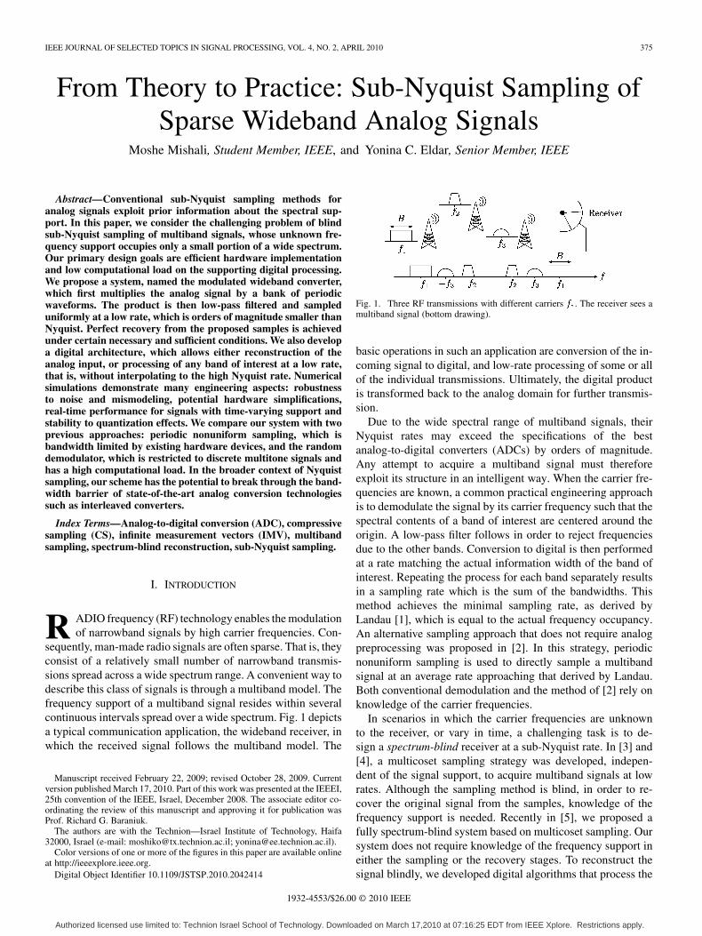
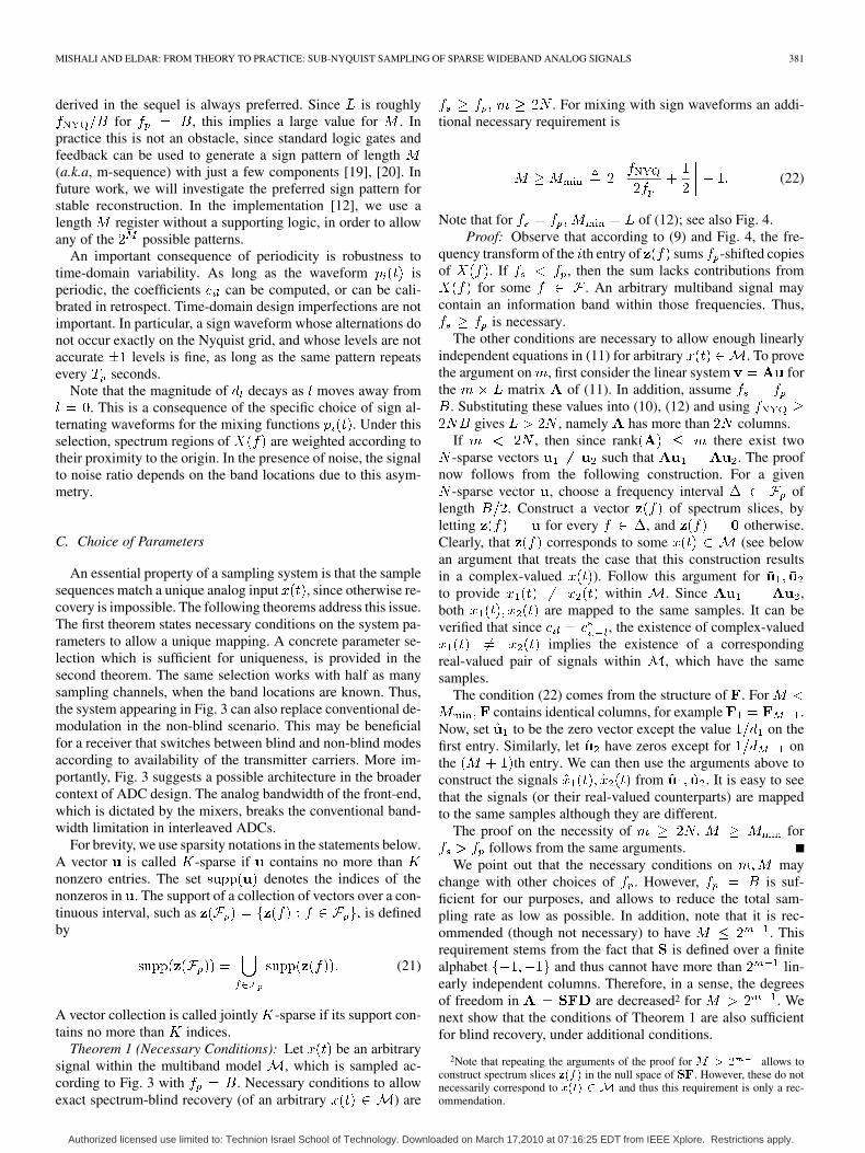
sequently, man-made radio signals are often sparse. That is, theyconsist of a relatively small number of narrowband transmis-sions spread across a wide spectrum range. A convenient way todescribe this class of signals is through a multiband model. Thefrequency support of a multiband signal resides within severalcontinuous intervals spread over a wide spectrum. Fig. 1 depictsa typical communication application, the wideband receiver, inwhich the received signal follows the multiband model. The
Manuscript received February 22, 2009; revised October 28, 2009. Currentversion published March 17, 2010. Part of this work was presented at the IEEEI,25th convention of the IEEE, Israel, December 2008. The associate editor co-ordinating the review of this manuscript and approving it for publication wasProf. Richard G. Baraniuk.
The authors are with the Technion—Israel Institute of Technology, Haifa32000, Israel (e-mail: [email protected]; [email protected]).
Color versions of one or more of the figures in this paper are available onlineat http://ieeexplore.ieee.org.
Digital Object Identifier 10.1109/JSTSP.2010.2042414
Fig. 1. Three RF transmissions with different carriers � . The receiver sees amultiband signal (bottom drawing).
basic operations in such an application are conversion of the in-coming signal to digital, and low-rate processing of some or allof the individual transmissions. Ultimately, the digital productis transformed back to the analog domain for further transmis-sion.
Due to the wide spectral range of multiband signals, theirNyquist rates may exceed the specifications of the bestanalog-to-digital converters (ADCs) by orders of magnitude.Any attempt to acquire a multiband signal must thereforeexploit its structure in an intelligent way. When the carrier fre-quencies are known, a common practical engineering approachis to demodulate the signal by its carrier frequency such that thespectral contents of a band of interest are centered around theorigin. A low-pass filter follows in order to reject frequenciesdue to the other bands. Conversion to digital is then performedat a rate matching the actual information width of the band ofinterest. Repeating the process for each band separately resultsin a sampling rate which is the sum of the bandwidths. Thismethod achieves the minimal sampling rate, as derived byLandau [1], which is equal to the actual frequency occupancy.An alternative sampling approach that does not require analogpreprocessing was proposed in [2]. In this strategy, periodicnonuniform sampling is used to directly sample a multibandsignal at an average rate approaching that derived by Landau.Both conventional demodulation and the method of [2] rely onknowledge of the carrier frequencies.
In scenarios in which the carrier frequencies are unknownto the receiver, or vary in time, a challenging task is to de-sign a spectrum-blind receiver at a sub-Nyquist rate. In [3] and[4], a multicoset sampling strategy was developed, indepen-dent of the signal support, to acquire multiband signals at lowrates. Although the sampling method is blind, in order to re-cover the original signal from the samples, knowledge of thefrequency support is needed. Recently in [5], we proposed afully spectrum-blind system based on multicoset sampling. Oursystem does not require knowledge of the frequency support ineither the sampling or the recovery stages. To reconstruct thesignal blindly, we developed digital algorithms that process the
1932-4553/$26.00 © 2010 IEEE
Authorized licensed use limited to: Technion Israel School of Technology. Downloaded on March 17,2010 at 07:16:25 EDT from IEEE Xplore. Restrictions apply.
376 IEEE JOURNAL OF SELECTED TOPICS IN SIGNAL PROCESSING, VOL. 4, NO. 2, APRIL 2010
samples and identify the unknown spectral support. Once thesupport is found, the continuous signal is reconstructed usingclosed-form expressions.
Periodic nonuniform sampling is a popular approach in thebroader context of analog conversion when the spectrum is fullyoccupied. Instead of implementing a single ADC at a high-rate
, interleaved ADCs use devices at rate with ap-propriate time shifts [6]–[8]. However, time interleaving hastwo fundamental limitations. First, the low-rate samplershave to share an analog front-end which must tolerate the inputbandwidth . With today’s technology the possible front-endsare still far below the wideband regime. Second, maintainingaccurate time shifts, on the order of , is difficult to im-plement. Multicoset sampling, is a special case of interleavedADCs, so that the same limitations apply. In Section II-B wediscuss in more detail the difficulty in implementing interleavedADCs and multicoset sampling. In practice, such systems arelimited to intermediate input frequencies and cannot deal withwideband inputs.
Recently, a new architecture to acquire multitone signals,called the random demodulator, was studied in the literature ofcompressed sensing (CS) [9], [10]. In this approach, the signalis modulated by a high-rate pseudorandom number generator,integrated, and sampled at a low rate. This scheme appliesto signals with finite set of harmonics chosen from a fixeduniform grid. Time-domain analysis shows that CS algorithmscan recover such a multitone signal from the proposed sam-ples [10]. However, as discussed in Section VI, truly analogsignals require a prohibitively large number of harmonics toapproximate them well within the discrete model, which inturn renders the reconstruction computationally infeasible andvery sensitive to the grid choice. Furthermore, the time-domainapproach precludes processing at a low rate, even for multitoneinputs, since interpolation to the Nyquist rate is an essentialingredient in the reconstruction.
In this paper, we aim to combine the advantages of the pre-vious approaches: The ability to treat analog multiband models,a sampling stage with a practical implementation, and a spec-trum-blind recovery stage which involves efficient digital pro-cessing. In addition, we would like a method that allows low-rate processing, namely the ability to process any one of thetransmitted bands without first requiring interpolation to thehigh Nyquist rate.
Our main contribution is an analog system, referred to as themodulated wideband converter (MWC), which is comprised ofa bank of modulators and low-pass filters. The signal is mul-tiplied by a periodic waveform, whose period corresponds tothe multiband model parameters. A square-wave alternating atthe Nyquist rate is one choice; other periodic waveforms arealso possible. The goal of the modulator is to alias the spec-trum into baseband. The modulated output is then low-pass fil-tered, and sampled at a low rate. The rate can be as low asthe expected width of an individual transmission. Based on fre-quency-domain arguments, we prove that an appropriate choiceof the parameters (waveform period, sampling rate) guaranteesthat our system uniquely determines a multiband input signal. Inaddition, we describe how to trade the number of channels bya higher rate in each branch, at the expense of additional pro-
cessing. Theoretically, this method allows to collapse the entiresystem to a single channel operating at a rate lower than Nyquist.
Our second contribution is a digital architecture which en-ables processing of the samples for various purposes. Recon-struction of the original analog input is one possible function.Perhaps more useful is the capability of the proposed system togenerate low-rate sequences corresponding to each of the bands,which, in principle, allow subsequent digital processing of eachband at a low rate. This architecture also has the ability to treatinputs with time-varying support. At the heart of the digital pro-cessing lies the continuous to finite (CTF) block from our pre-vious works [5], [11]. The CTF separates the support recoveryfrom the rest of the operations in the digital domain. In our pre-vious works, the CTF required costly digital processing at theNyquist rate, and therefore provided only analog reconstructionat the price of high rate computations. In contrast, here, the CTFcomputations are carried out directly on the low-rate samples.
The main theme of this paper is going from theory to prac-tice, namely tying together a theoretical sampling approach withpractical engineering aspects. Besides the uniqueness theoremsand stability conditions, we make use of extensive numericalsimulations, in Section V, to study typical wideband scenarios.The simulations demonstrate robustness to noise and signal mis-modeling, potential hardware simplifications in order to reducethe number of devices, fast adaption to time-varying spectralsupport, and the performance with quantized samples. A cir-cuit-level realization of the MWC is reported in [12].
This paper is organized as follows. Section II describes themultiband model and points out limitations of multicoset sam-pling in the wideband regime. In Section III, we describe theMWC system and provide a frequency-domain analysis of theresulting samples. This leads to a concrete parameter selectionwhich guarantees a unique signal matching the digital samples.We conclude the section with a discussion on the tradeoff be-tween the number of channels, rate, and complexity. The ar-chitecture for low-rate processing and recovery, is presented inSection IV. In Section V, we conduct a detailed numerical eval-uation of the proposed system. A review of related work con-cludes the paper in Section VI.
II. FORMULATION AND BACKGROUND
A. Problem Formulation
Let be a real-valued continuous-time signal in .Throughout the paper, continuous signals are assumed to bebandlimited to . Formally, the Fouriertransform of , which is defined by
(1)
is zero for every . We denote by the Nyquistrate of . For technical reasons, it is also assumed thatis piecewise continuous in . We treat signals from the multi-band model defined below.
Definition 1: The set contains all signals , such thatthe support of the Fourier transform is contained withina union of disjoint intervals (bands) in , and each of thebandwidths does not exceed .
Authorized licensed use limited to: Technion Israel School of Technology. Downloaded on March 17,2010 at 07:16:25 EDT from IEEE Xplore. Restrictions apply.
MISHALI AND ELDAR: FROM THEORY TO PRACTICE: SUB-NYQUIST SAMPLING OF SPARSE WIDEBAND ANALOG SIGNALS 377
Signals in have an even number of bands due to theconjugate symmetry of . The band positions are arbitrary,and in particular, unknown in advance. A typical spectral sup-port of a signal from the multiband model is illustrated in theexample of Fig. 1, in which and are dictatedby the specifications of the possible transmitters.
We wish to design a sampling system for signals from themodel that satisfies the following properties:
1) The sampling rate should be as low as possible;2) the system has no prior knowledge of the band locations;3) the system can be implemented with existing analog de-
vices and (preferably low-rate) ADCs.Together with the sampling stage we need to design a recon-
struction scheme, which converts the discrete samples back tothe continuous-time domain. This stage may involve digital pro-cessing prior to reconstruction. An implicit (but crucial) require-ment is that recovery involves a reasonable amount of computa-tions. Real-time applications may also necessitate short latencyfrom input to output and a constant throughput. Therefore, twomain factors dictate the input spectrum range that the overallsystem can handle: analog hardware at the required rate that canconvert the signal to digital, and a digital stage that can accom-modate the computational load.
In our previous work [5], we proved that the minimal sam-pling rate for to allow perfect blind reconstruction is ,provided that is lower than the Nyquist rate. The case
represents signals which occupy more thanhalf of the Nyquist range. No rate improvement is possible inthat case (for arbitrary signals), and thus we assume
in the sequel. Concrete algorithms for blind recovery,achieving the minimal rate, were developed in [5] based on amulticoset sampling strategy. The next section briefly describesthis method, which achieves the goals of minimal rate and blind-ness. However, limitations of practical ADCs, which we detailin the next section, render multicoset sampling impractical forwideband signals. As described later in Section III-A, the sam-pling scheme proposed in this paper circumvents these limita-tions and has other advantages in terms of practical implemen-tation.
B. Multicoset Using Practical ADCs
In multicoset sampling, samples of are obtained on a pe-riodic and nonuniform grid which is a subset of the Nyquist grid.Formally, denote by the sequence of samples taken at theNyquist rate. Let be a positive integer, and bea set of distinct integers with . Multicosetsamples consist of uniform sequences, called cosets, with theth coset defined by
(2)
Only cosets are used, so that the average sampling rateis , which is lower than the Nyquist rate .
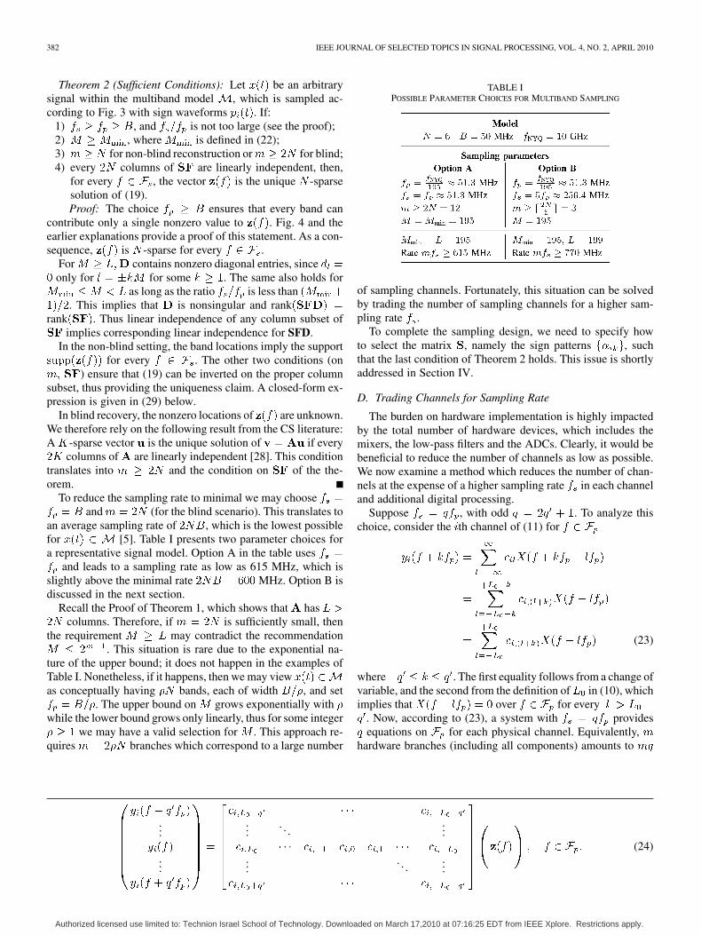
A possible implementation of the sampling sequences (2) isdepicted in Fig. 2(a). The building blocks are uniform sam-plers at rate , where the th sampler is shifted by from
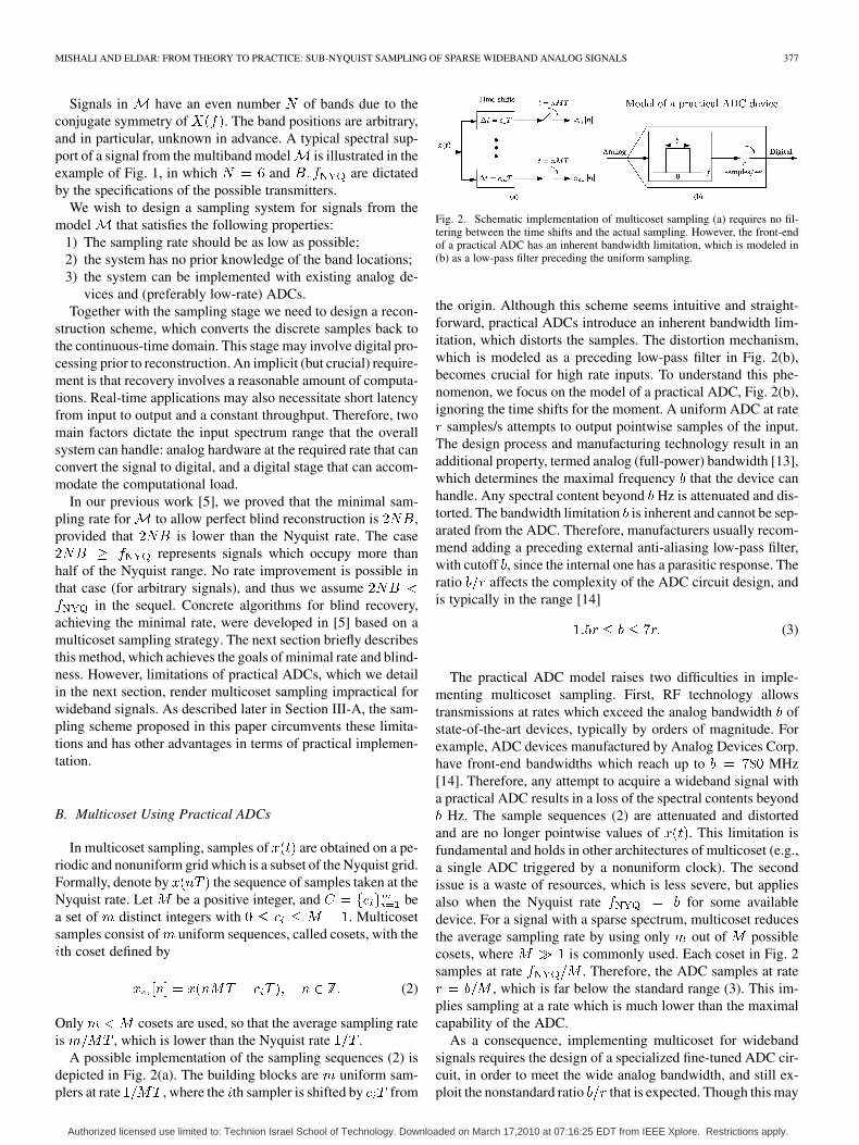
Fig. 2. Schematic implementation of multicoset sampling (a) requires no fil-tering between the time shifts and the actual sampling. However, the front-endof a practical ADC has an inherent bandwidth limitation, which is modeled in(b) as a low-pass filter preceding the uniform sampling.
the origin. Although this scheme seems intuitive and straight-forward, practical ADCs introduce an inherent bandwidth lim-itation, which distorts the samples. The distortion mechanism,which is modeled as a preceding low-pass filter in Fig. 2(b),becomes crucial for high rate inputs. To understand this phe-nomenon, we focus on the model of a practical ADC, Fig. 2(b),ignoring the time shifts for the moment. A uniform ADC at rate
samples/s attempts to output pointwise samples of the input.The design process and manufacturing technology result in anadditional property, termed analog (full-power) bandwidth [13],which determines the maximal frequency that the device canhandle. Any spectral content beyond Hz is attenuated and dis-torted. The bandwidth limitation is inherent and cannot be sep-arated from the ADC. Therefore, manufacturers usually recom-mend adding a preceding external anti-aliasing low-pass filter,with cutoff , since the internal one has a parasitic response. Theratio affects the complexity of the ADC circuit design, andis typically in the range [14]
(3)
The practical ADC model raises two difficulties in imple-menting multicoset sampling. First, RF technology allowstransmissions at rates which exceed the analog bandwidth ofstate-of-the-art devices, typically by orders of magnitude. Forexample, ADC devices manufactured by Analog Devices Corp.have front-end bandwidths which reach up to MHz[14]. Therefore, any attempt to acquire a wideband signal witha practical ADC results in a loss of the spectral contents beyond
Hz. The sample sequences (2) are attenuated and distortedand are no longer pointwise values of . This limitation isfundamental and holds in other architectures of multicoset (e.g.,a single ADC triggered by a nonuniform clock). The secondissue is a waste of resources, which is less severe, but appliesalso when the Nyquist rate for some availabledevice. For a signal with a sparse spectrum, multicoset reducesthe average sampling rate by using only out of possiblecosets, where is commonly used. Each coset in Fig. 2samples at rate . Therefore, the ADC samples at rate
, which is far below the standard range (3). This im-plies sampling at a rate which is much lower than the maximalcapability of the ADC.
As a consequence, implementing multicoset for widebandsignals requires the design of a specialized fine-tuned ADC cir-cuit, in order to meet the wide analog bandwidth, and still ex-ploit the nonstandard ratio that is expected. Though this may
Authorized licensed use limited to: Technion Israel School of Technology. Downloaded on March 17,2010 at 07:16:25 EDT from IEEE Xplore. Restrictions apply.
378 IEEE JOURNAL OF SELECTED TOPICS IN SIGNAL PROCESSING, VOL. 4, NO. 2, APRIL 2010
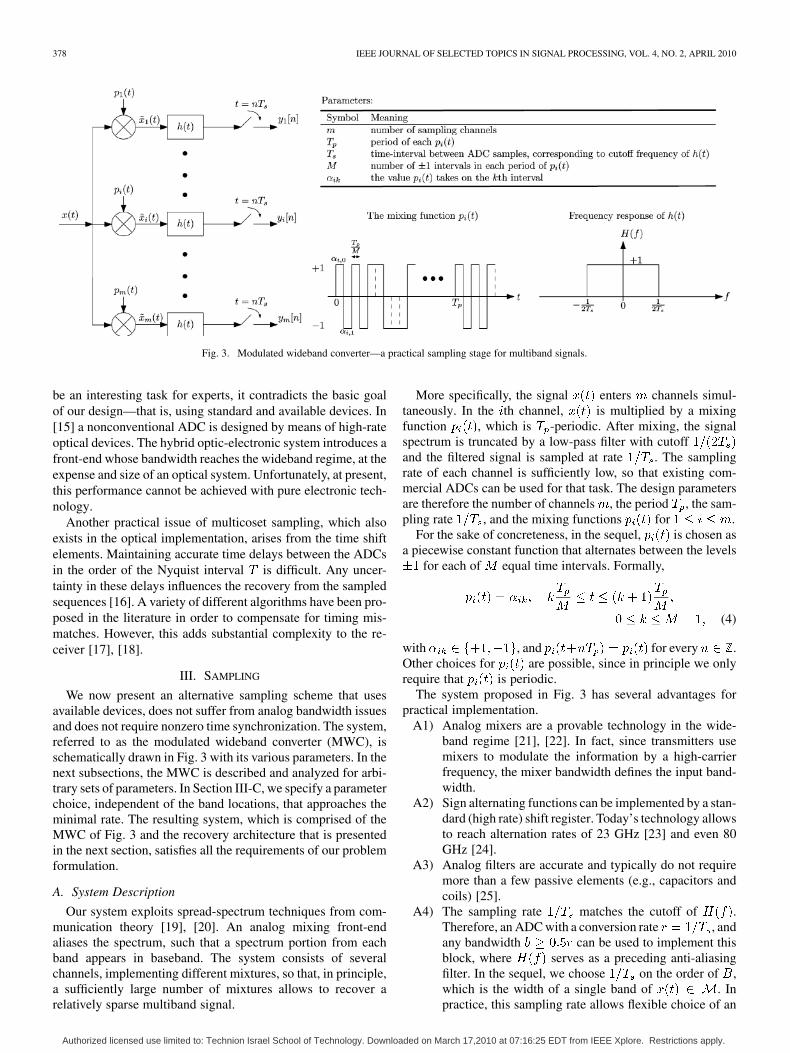
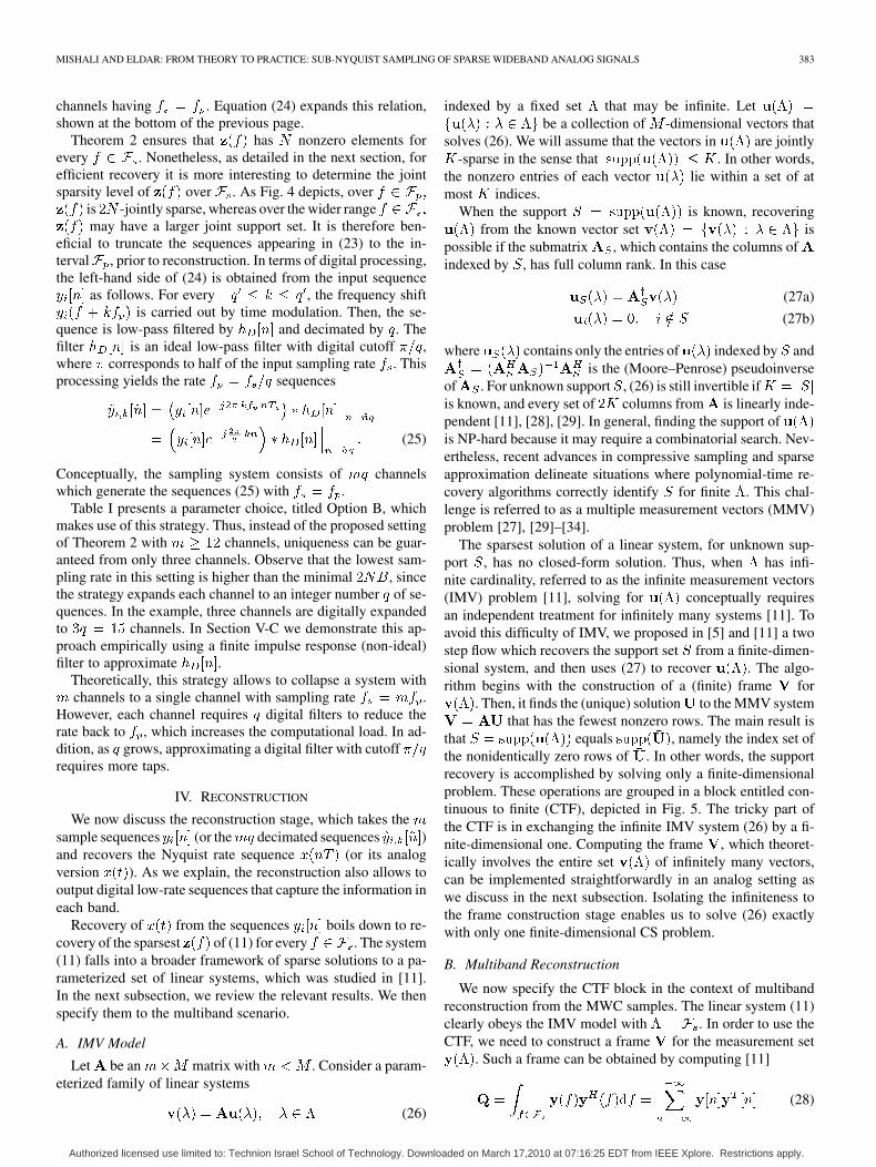
Fig. 3. Modulated wideband converter—a practical sampling stage for multiband signals.
be an interesting task for experts, it contradicts the basic goalof our design—that is, using standard and available devices. In[15] a nonconventional ADC is designed by means of high-rateoptical devices. The hybrid optic-electronic system introduces afront-end whose bandwidth reaches the wideband regime, at theexpense and size of an optical system. Unfortunately, at present,this performance cannot be achieved with pure electronic tech-nology.
Another practical issue of multicoset sampling, which alsoexists in the optical implementation, arises from the time shiftelements. Maintaining accurate time delays between the ADCsin the order of the Nyquist interval is difficult. Any uncer-tainty in these delays influences the recovery from the sampledsequences [16]. A variety of different algorithms have been pro-posed in the literature in order to compensate for timing mis-matches. However, this adds substantial complexity to the re-ceiver [17], [18].
III. SAMPLING
We now present an alternative sampling scheme that usesavailable devices, does not suffer from analog bandwidth issuesand does not require nonzero time synchronization. The system,referred to as the modulated wideband converter (MWC), isschematically drawn in Fig. 3 with its various parameters. In thenext subsections, the MWC is described and analyzed for arbi-trary sets of parameters. In Section III-C, we specify a parameterchoice, independent of the band locations, that approaches theminimal rate. The resulting system, which is comprised of theMWC of Fig. 3 and the recovery architecture that is presentedin the next section, satisfies all the requirements of our problemformulation.
A. System Description
Our system exploits spread-spectrum techniques from com-munication theory [19], [20]. An analog mixing front-endaliases the spectrum, such that a spectrum portion from eachband appears in baseband. The system consists of severalchannels, implementing different mixtures, so that, in principle,a sufficiently large number of mixtures allows to recover arelatively sparse multiband signal.
More specifically, the signal enters channels simul-taneously. In the th channel, is multiplied by a mixingfunction , which is -periodic. After mixing, the signalspectrum is truncated by a low-pass filter with cutoffand the filtered signal is sampled at rate . The samplingrate of each channel is sufficiently low, so that existing com-mercial ADCs can be used for that task. The design parametersare therefore the number of channels , the period , the sam-pling rate , and the mixing functions for .
For the sake of concreteness, in the sequel, is chosen asa piecewise constant function that alternates between the levels
for each of equal time intervals. Formally,
(4)
with , and for every .Other choices for are possible, since in principle we onlyrequire that is periodic.
The system proposed in Fig. 3 has several advantages forpractical implementation.
A1) Analog mixers are a provable technology in the wide-band regime [21], [22]. In fact, since transmitters usemixers to modulate the information by a high-carrierfrequency, the mixer bandwidth defines the input band-width.
A2) Sign alternating functions can be implemented by a stan-dard (high rate) shift register. Today’s technology allowsto reach alternation rates of 23 GHz [23] and even 80GHz [24].
A3) Analog filters are accurate and typically do not requiremore than a few passive elements (e.g., capacitors andcoils) [25].
A4) The sampling rate matches the cutoff of .Therefore, an ADC with a conversion rate , andany bandwidth can be used to implement thisblock, where serves as a preceding anti-aliasingfilter. In the sequel, we choose on the order of ,which is the width of a single band of . Inpractice, this sampling rate allows flexible choice of an
Authorized licensed use limited to: Technion Israel School of Technology. Downloaded on March 17,2010 at 07:16:25 EDT from IEEE Xplore. Restrictions apply.
MISHALI AND ELDAR: FROM THEORY TO PRACTICE: SUB-NYQUIST SAMPLING OF SPARSE WIDEBAND ANALOG SIGNALS 379
ADC from a variety of commercial devices in the lowrate regime.
A5) Sampling is synchronized in all channels, that is thereare no time shifts. This is beneficial since the trigger forall ADCs can be generated accurately (e.g., with a zero-delay synchronization device [26]). The same clock canbe used for a subsequent digital processor which re-ceives the sample sets at rate .
Note that the front-end preprocessing must be carried out byanalog means, since both the mixer and the analog filter operateon wideband signals, at rates which are far beyond digital pro-cessing capabilities. In fact, the mixer output is not ban-dlimited, and therefore there is no way to replace the analogfilter by a digital unit even if the converter is used for low-ratesignals. The purely analog front-end is the key to overcome thebandwidth limitation of ADCs.
B. Frequency Domain Analysis
We now derive the relation between the sample sequencesand the unknown signal . This analysis is used for
several purposes in the following sections. First, for specifyinga choice of parameters ensuring a unique mapping betweenand the sequences . Second, we use this analysis to explainthe reconstruction scheme. Finally, stability and implementationissues will also be based on this development. To this end, weintroduce the definitions
(5a)
(5b)
Consider the th channel. Since is -periodic, it has aFourier expansion
(6)
where
(7)
The Fourier transform of the analog multiplicationis evaluated as
(8)
Therefore, the input to is a linear combination of-shifted copies of . Since for , the
sum in (8) contains (at most) nonzero terms1.
1The ceiling operator ��� returns the greater (or equal) integer which isclosest to �.
The filter has a frequency response which is an idealrectangular function, as depicted in Fig. 3. Consequently, onlyfrequencies in the interval are contained in the uniform se-quence . Thus, the discrete-time Fourier transform (DTFT)of the th sequence is expressed as
(9)
where is defined in (5b), and is chosen as the smallestinteger such that the sum contains all nonzero contributions of
over . The exact value of is calculated by
(10)
Note that the mixer output is not bandlimited, and, theoret-ically, depending on the coefficients , the Fourier transform(8) may not be well defined. This technicality, however, is re-solved in (9) since the filter output involves only a finite numberof aliases of .
Relation (9) ties the known DTFTs of to the unknown. This equation is the key to recovery of . For our pur-
poses, it is convenient to write (9) in matrix form as
(11)
where is a vector of length with th element. The unknown vector
is of length
(12)
with
(13)
The matrix contains the coefficients
(14)
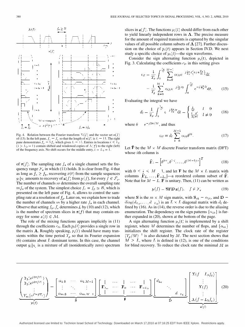
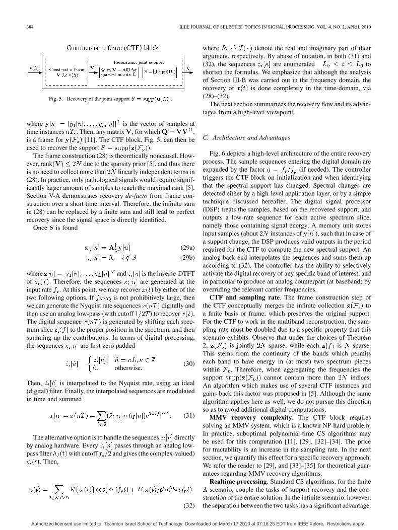
where the reverse order is due to the enumeration of in(13). Fig. 4 depicts the vector and the effect of aliasing
in -shifted copies for bands, aliasing rateand two sampling rates, and . Each
entry of represents a frequency slice of whose lengthis . Thus, in order to recover , it is sufficient to determine
in the interval .The analysis so far holds for every choice of -periodic func-
tions . Before proceeding, we discuss the role of each pa-rameter. The period determines the aliasing of by set-ting the shift intervals to . Equivalently, the aliasingrate controls the way the bands are arranged in the spectrumslices , as depicted in Fig. 4. We choose so thateach band contributes only a single nonzero element to(referring to a specific ), and consequently has at most
nonzeros. In practice is chosen slightly more than toavoid edge effects. Thus, the parameter is used to translatethe multiband prior to a bound on the sparsity level
Authorized licensed use limited to: Technion Israel School of Technology. Downloaded on March 17,2010 at 07:16:25 EDT from IEEE Xplore. Restrictions apply.
380 IEEE JOURNAL OF SELECTED TOPICS IN SIGNAL PROCESSING, VOL. 4, NO. 2, APRIL 2010
Fig. 4. Relation between the Fourier transform ���� and the vector set ����of (13). In the left pane, � � � so that the length of ���� is� � ��. The rightpane demonstrates � � �� which gives � � ��. Entries in locations � � �
�� � � � �� contain shifted and windowed copies of ���� to the right (left)of the frequency axis. No shift occurs for the middle entry, � � � � �.
of . The sampling rate of a single channel sets the fre-quency range in which (11) holds. It is clear from Fig. 4 thatas long as , recovering from the sample sequences
amounts to recovery of from , for every .The number of channels determines the overall sampling rate
of the system. The simplest choice , which ispresented on the left pane of Fig. 4, allows to control the sam-pling rate at a resolution of . Later on, we explain how to tradethe number of channels by a higher rate in each channel.Observe that setting determines by (10) and (12), whichis the number of spectrum slices in that may contain en-ergy for some .
The role of the mixing functions appears implicitly in (11)through the coefficients . Each provides a single row inthe matrix . Roughly speaking, should have many tran-sients within the time period so that its Fourier expansion(6) contains about dominant terms. In this case, the channeloutput is a mixture of all (nonidentically zero) spectrum
slices in . The functions should differ from each otherto yield linearly independent rows in . The precise measurefor the amount of required transients is captured by the singularvalues of all possible column subsets of [27]. Further discus-sion on the choice of appears in Section IV.D. We nextstudy a specific choice of —the sign waveforms.
Consider the sign alternating function , depicted inFig. 3. Calculating the coefficients in this setting gives
(15)
Evaluating the integral we have
(16)
where , and thus
(17)
Let be the discrete Fourier transform matrix (DFT)whose th column is
(18)
with , and let be the matrix withcolumns —a reordered column subset of .Note that for is unitary. Then, (11) can be written as
(19)
where is the sign matrix, with , andis an diagonal matrix with de-
fined by (16). As in (14), the reverse order is due to the aliasingenumeration. The dependency on the sign patterns is fur-ther expanded in (20), shown at the bottom of the page.
A sign alternating function is implemented by a shiftregister, where determines the number of flops, andinitializes the shift register. The clock rate of the register
is also dictated by . The next section shows that, where is defined in (12), is one of the conditions
for blind recovery. To reduce the clock rate the minimal as
......
. . ....
. . .
...
...
(20)
Authorized licensed use limited to: Technion Israel School of Technology. Downloaded on March 17,2010 at 07:16:25 EDT from IEEE Xplore. Restrictions apply.
MISHALI AND ELDAR: FROM THEORY TO PRACTICE: SUB-NYQUIST SAMPLING OF SPARSE WIDEBAND ANALOG SIGNALS 381
derived in the sequel is always preferred. Since is roughlyfor , this implies a large value for . In
practice this is not an obstacle, since standard logic gates andfeedback can be used to generate a sign pattern of length(a.k.a, m-sequence) with just a few components [19], [20]. Infuture work, we will investigate the preferred sign pattern forstable reconstruction. In the implementation [12], we use alength register without a supporting logic, in order to allowany of the possible patterns.
An important consequence of periodicity is robustness totime-domain variability. As long as the waveform isperiodic, the coefficients can be computed, or can be cali-brated in retrospect. Time-domain design imperfections are notimportant. In particular, a sign waveform whose alternations donot occur exactly on the Nyquist grid, and whose levels are notaccurate levels is fine, as long as the same pattern repeatsevery seconds.
Note that the magnitude of decays as moves away from. This is a consequence of the specific choice of sign al-
ternating waveforms for the mixing functions . Under thisselection, spectrum regions of are weighted according totheir proximity to the origin. In the presence of noise, the signalto noise ratio depends on the band locations due to this asym-metry.
C. Choice of Parameters
An essential property of a sampling system is that the samplesequences match a unique analog input , since otherwise re-covery is impossible. The following theorems address this issue.The first theorem states necessary conditions on the system pa-rameters to allow a unique mapping. A concrete parameter se-lection which is sufficient for uniqueness, is provided in thesecond theorem. The same selection works with half as manysampling channels, when the band locations are known. Thus,the system appearing in Fig. 3 can also replace conventional de-modulation in the non-blind scenario. This may be beneficialfor a receiver that switches between blind and non-blind modesaccording to availability of the transmitter carriers. More im-portantly, Fig. 3 suggests a possible architecture in the broadercontext of ADC design. The analog bandwidth of the front-end,which is dictated by the mixers, breaks the conventional band-width limitation in interleaved ADCs.
For brevity, we use sparsity notations in the statements below.A vector is called -sparse if contains no more thannonzero entries. The set denotes the indices of thenonzeros in . The support of a collection of vectors over a con-tinuous interval, such as is definedby
(21)
A vector collection is called jointly -sparse if its support con-tains no more than indices.
Theorem 1 (Necessary Conditions): Let be an arbitrarysignal within the multiband model , which is sampled ac-cording to Fig. 3 with . Necessary conditions to allowexact spectrum-blind recovery (of an arbitrary ) are
. For mixing with sign waveforms an addi-tional necessary requirement is
(22)
Note that for of (12); see also Fig. 4.Proof: Observe that according to (9) and Fig. 4, the fre-
quency transform of the th entry of sums -shifted copiesof . If , then the sum lacks contributions from
for some . An arbitrary multiband signal maycontain an information band within those frequencies. Thus,
is necessary.The other conditions are necessary to allow enough linearly
independent equations in (11) for arbitrary . To provethe argument on , first consider the linear system forthe matrix of (11). In addition, assume
. Substituting these values into (10), (12) and usinggives , namely has more than columns.
If , then since rank there exist two-sparse vectors such that . The proof
now follows from the following construction. For a given-sparse vector , choose a frequency interval of
length . Construct a vector of spectrum slices, byletting for every , and otherwise.Clearly, that corresponds to some (see belowan argument that treats the case that this construction resultsin a complex-valued ). Follow this argument forto provide within . Since ,both are mapped to the same samples. It can beverified that since , the existence of complex-valued
implies the existence of a correspondingreal-valued pair of signals within , which have the samesamples.
The condition (22) comes from the structure of . Forcontains identical columns, for example .
Now, set to be the zero vector except the value on thefirst entry. Similarly, let have zeros except for onthe th entry. We can then use the arguments above toconstruct the signals from . It is easy to seethat the signals (or their real-valued counterparts) are mappedto the same samples although they are different.
The proof on the necessity of forfollows from the same arguments.
We point out that the necessary conditions on maychange with other choices of . However, is suf-ficient for our purposes, and allows to reduce the total sam-pling rate as low as possible. In addition, note that it is rec-ommended (though not necessary) to have . Thisrequirement stems from the fact that is defined over a finitealphabet and thus cannot have more than lin-early independent columns. Therefore, in a sense, the degreesof freedom in are decreased2 for . Wenext show that the conditions of Theorem 1 are also sufficientfor blind recovery, under additional conditions.
2Note that repeating the arguments of the proof for � � � allows toconstruct spectrum slices ���� in the null space of ��. However, these do notnecessarily correspond to ���� � � and thus this requirement is only a rec-ommendation.
Authorized licensed use limited to: Technion Israel School of Technology. Downloaded on March 17,2010 at 07:16:25 EDT from IEEE Xplore. Restrictions apply.
382 IEEE JOURNAL OF SELECTED TOPICS IN SIGNAL PROCESSING, VOL. 4, NO. 2, APRIL 2010
Theorem 2 (Sufficient Conditions): Let be an arbitrarysignal within the multiband model , which is sampled ac-cording to Fig. 3 with sign waveforms . If:
1) , and is not too large (see the proof);2) , where is defined in (22);3) for non-blind reconstruction or for blind;4) every columns of are linearly independent, then,
for every , the vector is the unique -sparsesolution of (19).Proof: The choice ensures that every band can
contribute only a single nonzero value to . Fig. 4 and theearlier explanations provide a proof of this statement. As a con-sequence, is -sparse for every .
For contains nonzero diagonal entries, sinceonly for for some . The same also holds for
as long as the ratio is less than. This implies that is nonsingular and rank
rank . Thus linear independence of any column subset ofimplies corresponding linear independence for SFD.
In the non-blind setting, the band locations imply the supportfor every . The other two conditions (on
) ensure that (19) can be inverted on the proper columnsubset, thus providing the uniqueness claim. A closed-form ex-pression is given in (29) below.
In blind recovery, the nonzero locations of are unknown.We therefore rely on the following result from the CS literature:A -sparse vector is the unique solution of if every
columns of are linearly independent [28]. This conditiontranslates into and the condition on of the the-orem.
To reduce the sampling rate to minimal we may chooseand (for the blind scenario). This translates to
an average sampling rate of , which is the lowest possiblefor [5]. Table I presents two parameter choices fora representative signal model. Option A in the table uses
and leads to a sampling rate as low as 615 MHz, which isslightly above the minimal rate MHz. Option B isdiscussed in the next section.
Recall the Proof of Theorem 1, which shows that hascolumns. Therefore, if is sufficiently small, then
the requirement may contradict the recommendation. This situation is rare due to the exponential na-
ture of the upper bound; it does not happen in the examples ofTable I. Nonetheless, if it happens, then we may viewas conceptually having bands, each of width , and set
. The upper bound on grows exponentially withwhile the lower bound grows only linearly, thus for some integer
we may have a valid selection for . This approach re-quires branches which correspond to a large number
TABLE IPOSSIBLE PARAMETER CHOICES FOR MULTIBAND SAMPLING
of sampling channels. Fortunately, this situation can be solvedby trading the number of sampling channels for a higher sam-pling rate .
To complete the sampling design, we need to specify howto select the matrix , namely the sign patterns , suchthat the last condition of Theorem 2 holds. This issue is shortlyaddressed in Section IV.
D. Trading Channels for Sampling Rate
The burden on hardware implementation is highly impactedby the total number of hardware devices, which includes themixers, the low-pass filters and the ADCs. Clearly, it would bebeneficial to reduce the number of channels as low as possible.We now examine a method which reduces the number of chan-nels at the expense of a higher sampling rate in each channeland additional digital processing.
Suppose , with odd . To analyze thischoice, consider the th channel of (11) for
(23)
where . The first equality follows from a change ofvariable, and the second from the definition of in (10), whichimplies that over for every
. Now, according to (23), a system with providesequations on for each physical channel. Equivalently,
hardware branches (including all components) amounts to
...
...
.... . .
...
.... . .
...
(24)
Authorized licensed use limited to: Technion Israel School of Technology. Downloaded on March 17,2010 at 07:16:25 EDT from IEEE Xplore. Restrictions apply.
MISHALI AND ELDAR: FROM THEORY TO PRACTICE: SUB-NYQUIST SAMPLING OF SPARSE WIDEBAND ANALOG SIGNALS 383
channels having . Equation (24) expands this relation,shown at the bottom of the previous page.
Theorem 2 ensures that has nonzero elements forevery . Nonetheless, as detailed in the next section, forefficient recovery it is more interesting to determine the jointsparsity level of over . As Fig. 4 depicts, over
is -jointly sparse, whereas over the wider rangemay have a larger joint support set. It is therefore ben-
eficial to truncate the sequences appearing in (23) to the in-terval , prior to reconstruction. In terms of digital processing,the left-hand side of (24) is obtained from the input sequence
as follows. For every , the frequency shiftis carried out by time modulation. Then, the se-
quence is low-pass filtered by and decimated by . Thefilter is an ideal low-pass filter with digital cutoff ,where corresponds to half of the input sampling rate . Thisprocessing yields the rate sequences
(25)
Conceptually, the sampling system consists of channelswhich generate the sequences (25) with .
Table I presents a parameter choice, titled Option B, whichmakes use of this strategy. Thus, instead of the proposed settingof Theorem 2 with channels, uniqueness can be guar-anteed from only three channels. Observe that the lowest sam-pling rate in this setting is higher than the minimal , sincethe strategy expands each channel to an integer number of se-quences. In the example, three channels are digitally expandedto channels. In Section V-C we demonstrate this ap-proach empirically using a finite impulse response (non-ideal)filter to approximate .
Theoretically, this strategy allows to collapse a system withchannels to a single channel with sampling rate .
However, each channel requires digital filters to reduce therate back to , which increases the computational load. In ad-dition, as grows, approximating a digital filter with cutoffrequires more taps.
IV. RECONSTRUCTION
We now discuss the reconstruction stage, which takes thesample sequences (or the decimated sequences )and recovers the Nyquist rate sequence (or its analogversion ). As we explain, the reconstruction also allows tooutput digital low-rate sequences that capture the information ineach band.
Recovery of from the sequences boils down to re-covery of the sparsest of (11) for every . The system(11) falls into a broader framework of sparse solutions to a pa-rameterized set of linear systems, which was studied in [11].In the next subsection, we review the relevant results. We thenspecify them to the multiband scenario.
A. IMV Model
Let be an matrix with . Consider a param-eterized family of linear systems
(26)
indexed by a fixed set that may be infinite. Letbe a collection of -dimensional vectors that
solves (26). We will assume that the vectors in are jointly-sparse in the sense that . In other words,
the nonzero entries of each vector lie within a set of atmost indices.
When the support is known, recoveringfrom the known vector set is
possible if the submatrix , which contains the columns ofindexed by , has full column rank. In this case
(27a)
(27b)
where contains only the entries of indexed by andis the (Moore–Penrose) pseudoinverse
of . For unknown support , (26) is still invertible ifis known, and every set of columns from is linearly inde-pendent [11], [28], [29]. In general, finding the support ofis NP-hard because it may require a combinatorial search. Nev-ertheless, recent advances in compressive sampling and sparseapproximation delineate situations where polynomial-time re-covery algorithms correctly identify for finite . This chal-lenge is referred to as a multiple measurement vectors (MMV)problem [27], [29]–[34].
The sparsest solution of a linear system, for unknown sup-port , has no closed-form solution. Thus, when has infi-nite cardinality, referred to as the infinite measurement vectors(IMV) problem [11], solving for conceptually requiresan independent treatment for infinitely many systems [11]. Toavoid this difficulty of IMV, we proposed in [5] and [11] a twostep flow which recovers the support set from a finite-dimen-sional system, and then uses (27) to recover . The algo-rithm begins with the construction of a (finite) frame for
. Then, it finds the (unique) solution to the MMV systemthat has the fewest nonzero rows. The main result is
that equals , namely the index set ofthe nonidentically zero rows of . In other words, the supportrecovery is accomplished by solving only a finite-dimensionalproblem. These operations are grouped in a block entitled con-tinuous to finite (CTF), depicted in Fig. 5. The tricky part ofthe CTF is in exchanging the infinite IMV system (26) by a fi-nite-dimensional one. Computing the frame , which theoret-ically involves the entire set of infinitely many vectors,can be implemented straightforwardly in an analog setting aswe discuss in the next subsection. Isolating the infiniteness tothe frame construction stage enables us to solve (26) exactlywith only one finite-dimensional CS problem.
B. Multiband Reconstruction
We now specify the CTF block in the context of multibandreconstruction from the MWC samples. The linear system (11)clearly obeys the IMV model with . In order to use theCTF, we need to construct a frame for the measurement set
. Such a frame can be obtained by computing [11]
(28)
Authorized licensed use limited to: Technion Israel School of Technology. Downloaded on March 17,2010 at 07:16:25 EDT from IEEE Xplore. Restrictions apply.
384 IEEE JOURNAL OF SELECTED TOPICS IN SIGNAL PROCESSING, VOL. 4, NO. 2, APRIL 2010
Fig. 5. Recovery of the joint support � � ����������.
where is the vector of samples attime instances . Then, any matrix , for which ,is a frame for [11]. The CTF block, Fig. 5, can then beused to recover the support .
The frame construction (28) is theoretically noncausal. How-ever, rank due to the sparsity prior [5], and thus thereis no need to collect more than linearly independent terms in(28). In practice, only pathological signals would require signif-icantly larger amount of samples to reach the maximal rank [5].Section V-A demonstrates recovery de-facto from frame con-struction over a short time interval. Therefore, the infinite sumin (28) can be replaced by a finite sum and still lead to perfectrecovery since the signal space is directly identified.
Once is found
(29a)
(29b)
where and is the inverse-DTFTof . Therefore, the sequences are generated at theinput rate . At this point, we may recover by either of thetwo following options. If is not prohibitively large, thenwe can generate the Nyquist rate sequences digitally andthen use an analog low-pass (with cutoff ) to recover .The digital sequence is generated by shifting each spec-trum slice to the proper position in the spectrum, and thensumming up the contributions. In terms of digital processing,the sequences are first zero padded
otherwise(30)
Then, is interpolated to the Nyquist rate, using an ideal(digital) filter. Finally, the interpolated sequences are modulatedin time and summed
(31)
The alternative option is to handle the sequences directlyby analog hardware. Every passes through an analog low-pass filter with cutoff and gives (the complex-valued)
. Then,
(32)
where denote the real and imaginary part of theirargument, respectively. By abuse of notation, in both (31) and(32), the sequences are enumerated toshorten the formulas. We emphasize that although the analysisof Section III-B was carried out in the frequency domain, therecovery of is done completely in the time-domain, via(28)–(32).
The next section summarizes the recovery flow and its advan-tages from a high-level viewpoint.
C. Architecture and Advantages
Fig. 6 depicts a high-level architecture of the entire recoveryprocess. The sample sequences entering the digital domain areexpanded by the factor (if needed). The controllertriggers the CTF block on initialization and when identifyingthat the spectral support has changed. Spectral changes aredetected either by a high-level application layer, or by a simpletechnique discussed hereafter. The digital signal processor(DSP) treats the samples, based on the recovered support, andoutputs a low-rate sequence for each active spectrum slice,namely those containing signal energy. A memory unit storesinput samples (about instances of ), such that in case ofa support change, the DSP produces valid outputs in the periodrequired for the CTF to compute the new spectral support. Ananalog back-end interpolates the sequences and sums them upaccording to (32). The controller has the ability to selectivelyactivate the digital recovery of any specific band of interest, andin particular to produce an analog counterpart (at baseband) byoverriding the relevant carrier frequencies.
CTF and sampling rate. The frame construction step ofthe CTF conceptually merges the infinite collection toa finite basis or frame, which preserves the original support.For the CTF to work in the multiband reconstruction, the sam-pling rate must be doubled due to a specific property that thisscenario exhibits. Observe that under the choices of Theorem2, is jointly -sparse, while each is -sparse.This stems from the continuity of the bands which permitseach band to have energy in (at most) two spectrum pieceswithin . Therefore, when aggregating the frequencies thesupport cannot contain more than indices.An algorithm which makes use of several CTF instances andgains back this factor was proposed in [5]. Although the samealgorithm applies here as well, we do not pursue this directionso as to avoid additional digital computations.
MMV recovery complexity. The CTF block requiressolving an MMV system, which is a known NP-hard problem.In practice, suboptimal polynomial-time CS algorithms maybe used for this computation [11], [29], [32]–[34]. The pricefor tractability is an increase in the sampling rate. In the nextsection, we quantify this effect for a specific recovery approach.We refer the reader to [29], and [33]–[35] for theoretical guar-antees regarding MMV recovery algorithms.
Realtime processing. Standard CS algorithms, for the finitescenario, couple the tasks of support recovery and the con-
struction of the entire solution. In the infinite scenario, however,the separation between the two tasks has a significant advantage.
Authorized licensed use limited to: Technion Israel School of Technology. Downloaded on March 17,2010 at 07:16:25 EDT from IEEE Xplore. Restrictions apply.
MISHALI AND ELDAR: FROM THEORY TO PRACTICE: SUB-NYQUIST SAMPLING OF SPARSE WIDEBAND ANALOG SIGNALS 385
The support recovery step yields an MMV system, whose di-mensions are . Thus, we can control the recovery problemsize by setting the number of channels , and setting via
in (12). Once the support is known, the actual recoveryhas a closed form (29), and can be carried out in real-time. In-deed, even the recovery of the Nyquist rate sequence (30)–(32),can be done at a constant rate. Had these tasks been coupled,the reconstruction stage would have to recover the Nyquist ratesignal directly. In turn, the CS algorithm would have to run on ahuge-scale system, dictated by the ambient Nyquist dimension,which is time and memory consuming.
In the context of real-time processing, we comment that theCTF is executed only when the spectral support changes, andthus the short delay introduced by its execution is negligible onaverage. In a real-time environment, about consecutive inputvectors should be stored in memory, so that in case of asupport change the CTF has enough time to provide a new sup-port estimate before the recovery of , (29), reaches the pointthat this information is needed. The experiment in Section V-Ddemonstrates such a real-time solution. In either case, there isno need to recover the Nyquist rate signal before a higher appli-cation layer can access the digital information.
In order to notice the support changes once they occur, we caneither rely an indication from the application layer, or automat-ically identify the spectral variation in the sequences . Toimplement the latter option, let be the last sup-port estimate of the CTF, and define for some entry
. Now, monitor the value of the sequence . As long asthe support does not change, the sparsity of implies that
or contains only small values due to noise. Whenever,this sequence crosses a threshold (for certain number of consec-utive time instances) trigger the CTF to obtain a new supportestimate. Note that the recovery of requires to implementonly one row from . Since, the values are not important forthe detection purpose, the multiplication can be carried out at alow resolution.
Robustness and sensitivity. The entire system, sampling andreconstruction, is robust against inaccuracies in the parameters
. This is a consequence of setting the parameters accordingto Theorem 2, with only the inequalities . In par-ticular, is chosen above the minimal to ensure safety guardregions against hardware inaccuracies or signal mismodeling.Furthermore, observe that the exact values of do not ap-pear anywhere in the recovery flow: the expanding (25), theframe construction (28), the CTF block—Fig. 5, and the re-covery (29). Only the ratio is used, which remainsunchanged if the a single clock circuitry is used in the design.In addition, in the recovery of the Nyquist rate sequence (31),only the ratio is used, which remains fixed for the samereasons. When recovering via (32), is provided to theback-end from the same clock triggering the sampling stage.The recovery is also stable in the presence of noise as numeri-cally demonstrated in Section V-A.
Digital implementation. The sample vectors arrive syn-chronously to the digital domain. As mentioned earlier, a pos-sible interface is to trigger a digital processor from the sameclock driving the ADCs, namely at rate . Since the dig-ital input rate is relatively low, on the order of Hz, commer-
cial cheap DSPs can be used. However, here the actual numberof channels has a great impact. Each sample is quantizedby the ADC to a certain number of bits, say 8 or 16. The buswidth towards the DSP becomes of length 8 m or 16 m, respec-tively. Care must be taken when choosing the processing unitin order to accommodate the bus width. Note that some recentDSPs have analog inputs with built-in synchronized ADCs soas to avoid such a problem. See other aspects of quantization inSection V-E.
Finally, we point out an advantage with respect to the recon-struction of a multicoset-based receiver. The IMV formulationholds for this strategy with a different sampling matrix [5].However, the IMV system requires a (Nyquist rate) zero paddedversion of (2) in this case. Consequently, constructing a frame
from the multicoset low-rate sequences (2) requires interpo-lating the sample sequences to the Nyquist rate. Only then can
be computed [see (61)–(62) in [5]]. Furthermore, reconstruc-tion of the signal also requires the same interpolation to theNyquist grid, that is even for a known spectral support. In con-trast, the current mixing stage has the advantage that the IMVis expressed directly in terms of the low-rate sequences ,and the computation of in (28) is carried out directly on theinput sequences. In fact, one may implement an adaptive frameconstruction at the input rate . Digital processing at rateis obviously preferred over a processor running at the Nyquistrate.
D. Choosing the Sign Patterns
Theorem 2 requires that for uniqueness, every columns ofmust be linearly independent. To apply the CTF block the
requirement is strengthened to every columns, which alsoimplies the minimal number of rows in [5]. Verifying that aset of sign patterns satisfies such a condition is computa-tionally difficult because one must check the rank of every setof columns from . In practice, when noise is present orwhen solving the MMV by suboptimal polynomial-time CS al-gorithms, the number of rows in should be increased beyond
. A preliminary discussion on the required dimensionsof is quoted below from the conference version of this work[36]. The actual choice of the patterns will be investigated in fu-ture work.
Consider the system , where is an unknown sparsevector, is the measurement vector, and is of size . Amatrix is said to have the restricted isometry property (RIP)[27] of order , if there exists such that
(33)
for every -sparse vector [27]. The requirement of Theorem2 thus translates to . The RIP requirement is also hard toverify for a given matrix. Instead, it can be easier to prove that arandom , chosen from some distribution, has the RIP with highprobability. In particular, it is known that a random sign matrix,whose entries are drawn independently with equal probability,has the RIP of order if , where is apositive constant independent of everything [37]. The log factoris necessary [38]. The RIP of matrices with random signs re-mains unchanged under any fixed unitary transform of the rows
Authorized licensed use limited to: Technion Israel School of Technology. Downloaded on March 17,2010 at 07:16:25 EDT from IEEE Xplore. Restrictions apply.
386 IEEE JOURNAL OF SELECTED TOPICS IN SIGNAL PROCESSING, VOL. 4, NO. 2, APRIL 2010
Fig. 6. High-level architecture for efficient multiband reconstruction.
[37]. This implies that if is a random sign matrix, possiblyimplemented by a length shift register per channel, thenhas the RIP of order for the above dimension selection. Notethat is ignored in this analysis, since the diagonal has nonzeroentries and thus for any vector .
To proceed, observe that solving for would require the com-binatorial search implied by
(34)
A popular approach is to approximate the sparsest solution by
(35)
The relaxed program, named basis pursuit (BP) [39], is convexand can be tackled with polynomial-time solvers [27]. Manyworks have analyzed the basis pursuit method and its ability torecover the sparsest vector . For example, ifthen (35) recovers the sparsest [40]. The squared error of therecovery in the presence of noise or model mismatch was alsoshown to be bounded under the same condition [40]. Similarconditions were shown to hold for other recovery algorithms.In particular, [35] proved a similar argument for a mixedprogram in the MMV setting (which incorporates the joint spar-sity prior). See also [34].
In practice, the matrix is not random once the samplingstage is implemented, and its RIP constant cannot be calcu-lated efficiently. A reviewer also pointed out that when imple-menting a binary sequence using feedback logic, as popular form-sequences, the set of possible sign patterns is much smallerthan . In this setting, alternative randomness properties, suchas almost -wise independency can be beneficial [41]. Exten-sive simulations on synthesized data are often used to evaluatethe performance and the stability of a CS system when RIPvalues are difficult to compute (e.g., see [11], [29], and [31]).Clearly, the numerical results do not ensure a desired RIP con-stant. Nonetheless, for practical applications, the behavior ob-served in simulations may be sufficient. The discussion aboveimplies that stable recovery of the MMV of Fig. 5 requiresroughly
(36)
channels to estimate the correct support, using polynomial-timealgorithms.
V. NUMERICAL SIMULATIONS
We now demonstrate several engineering aspects of oursystem, using numerical experiments.
1) A wideband design example in the presence of widebandnoise, for a synthesized signal with rectangular transmis-sion shapes.
2) Hardware simplifications: using a single shift-register toimplement several periodic waveforms at once.
3) Collapsing the number of hardware channels, evaluatingthe idea presented in Section III-D.
4) Fast adaption to time-varying support, for quadrature phaseshift keying (QPSK) transmissions.
5) Quantization effects.
A. Design Example
To evaluate the performance of the proposed system (seeFig. 3) we simulate the system on test signals contaminated bywhite Gaussian noise.
More precisely, we evaluate the performance on 500 noisytest signals of the form , where is a multibandsignal and is a white Gaussian noise process. The multibandmodel of Table I is used hereafter. The signal consists of threepairs of bands (total ), each of width MHz,constructed using the formula
(37)
where . The energy coefficients areand the time offsets are s.
The exact values takes on the support do not affect theresults and thus are fixed in all our simulations. Forevery signal the carriers are chosen uniformly at random in
with GHz.We design the sampling stage according to “Option A” of
Table I. Specifically, MHz. Thenumber of channels is set to , where each mixingfunction alternates sign at most times.Each sign is chosen uniformly at random and fixed for theduration of the experiment. To represent continuous signalsin simulation, we place a dense grid of 50 001 equispacedpoints in the time interval s . The time resolution underthis choice, , is used for accurate representation of thesignal after mixing, which is not band-limited. The Gaussiannoise is added and scaled so that the test signal has the desiredsignal-to-noise ratio (SNR), where the SNR is defined to be
, with the standard norms. To imitatethe analog filtering and sampling, we use a lengthy digital FIRfilter followed by decimation at the appropriate factor. Afterremoving the delay caused by this filter, we end up with 40
Authorized licensed use limited to: Technion Israel School of Technology. Downloaded on March 17,2010 at 07:16:25 EDT from IEEE Xplore. Restrictions apply.
MISHALI AND ELDAR: FROM THEORY TO PRACTICE: SUB-NYQUIST SAMPLING OF SPARSE WIDEBAND ANALOG SIGNALS 387
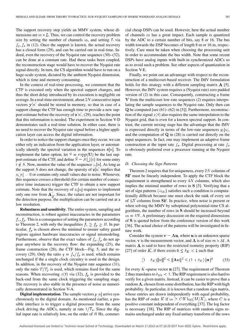
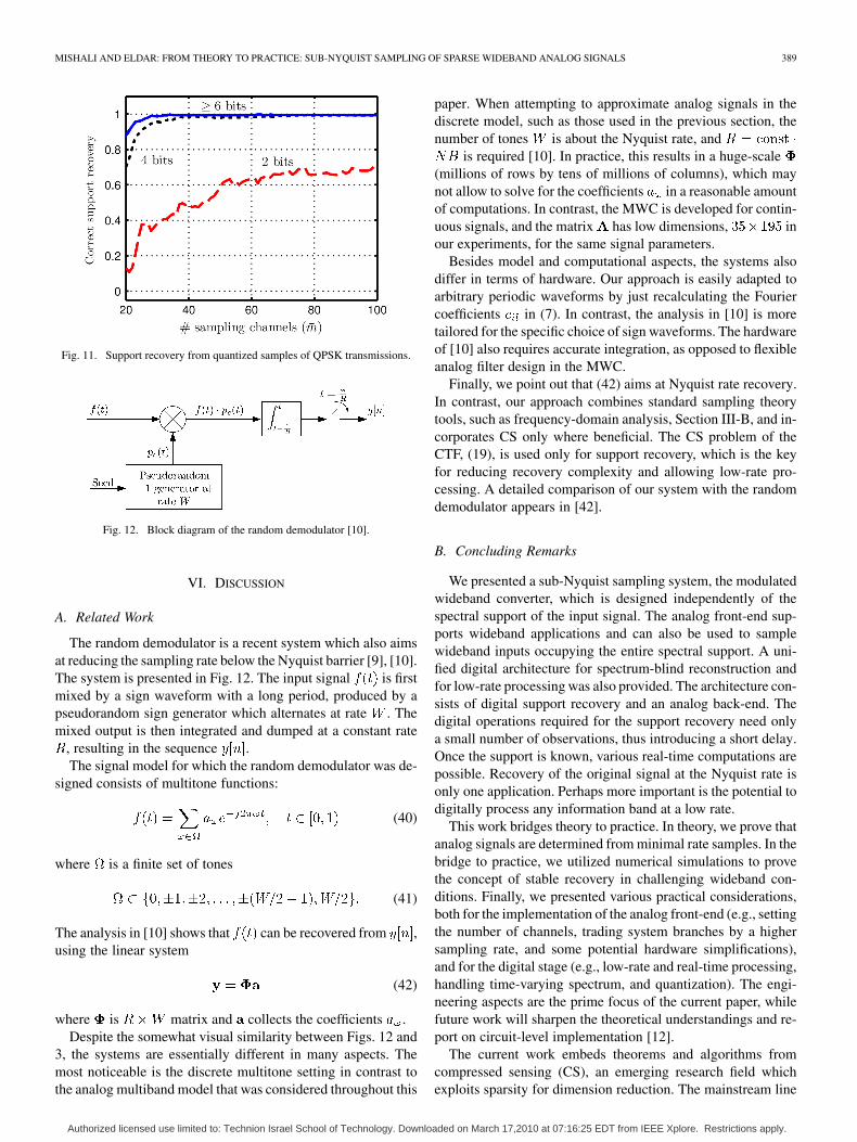
Fig. 7. Image intensity represents percentage of correct support set recovery�� � �, for reconstruction from different number of sampling sequences �� andunder several SNR levels.
samples per channel at rate , which corresponds to observingthe signal for 780 ns. We emphasize that these steps are re-quired only when simulating an analog hardware numerically.In practice, the continuous signals pass through an analog filter(e.g., an elliptic filter), and there is no need for decimation or adense time grid.
The support of the input signal is reconstructed fromchannels. (More precisely, is recovered.)We follow the procedure described in Fig. 5 to reduce the IMVsystem (19) to an MMV system. Due to Theorem 2, is ex-pected to have (at most) dominant eigenvectors. Thenoise space, which is associated with the remaining negligibleeigenvalues is discarded by simple thresholding ( is usedin the simulations). Then, the frame is constructed and theMMV is solved using simultaneous orthogonal matching pur-suit [31], [32]. We slightly modified the algorithm to select asymmetric pair of support indices in every iteration, based onthe conjugate symmetry of . Success recovery is declaredwhen the estimated support set is equal the true support, .Correct recovery is also considered when contains a fewadditional entries, as long as the corresponding columns arelinearly independent. As explained, recovery of the Nyquist ratesignal can be carried out by (31)–(32). Fig. 7 reports the per-centage of correct support recoveries for various numbers ofchannels and several SNRs.
The results show that in the high SNR regime correct recoveryis accomplished when using channels, which amountsto less than 18% of the Nyquist rate. This rate conforms with(36) which predicts an order of channelsfor stable recovery. A saving factor 2 is possible if using morethan a single CTF block and a complicated processing (see [5]for details) or by brute-force MMV solvers with exponentialrecovery time. An obvious trend which appears in the results isthat the recovery rate is inversely proportional to the SNR leveland to the number of channels used for reconstruction.
B. Simplifying the Mixing Stage
Each channel needs a mixing function , which suppos-edly requires a shift register of flip flops. In the setting of
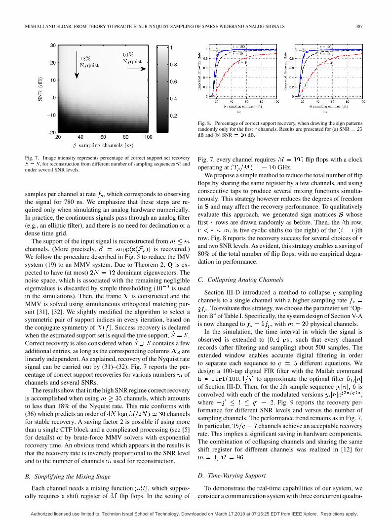
Fig. 8. Percentage of correct support recovery, when drawing the sign patternsrandomly only for the first � channels. Results are presented for (a) SNR � ��
dB and (b) SNR � �� dB.
Fig. 7, every channel requires flip flops with a clockoperating at GHz.
We propose a simple method to reduce the total number of flipflops by sharing the same register by a few channels, and usingconsecutive taps to produce several mixing functions simulta-neously. This strategy however reduces the degrees of freedomin and may affect the recovery performance. To qualitativelyevaluate this approach, we generated sign matrices whosefirst rows are drawn randomly as before. Then, the th row,
, is five cyclic shifts (to the right) of the throw. Fig. 8 reports the recovery success for several choices ofand two SNR levels. As evident, this strategy enables a saving of80% of the total number of flip flops, with no empirical degra-dation in performance.
C. Collapsing Analog Channels
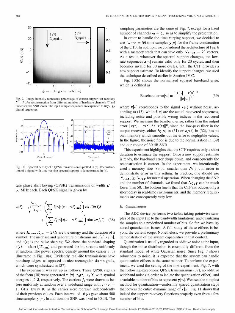
Section III-D introduced a method to collapse samplingchannels to a single channel with a higher sampling rate
. To evaluate this strategy, we choose the parameter set “Op-tion B” of Table I. Specifically, the system design of Section V-Ais now changed to , with physical channels.
In the simulation, the time interval in which the signal isobserved is extended to s , such that every channelrecords (after filtering and sampling) about 500 samples. Theextended window enables accurate digital filtering in orderto separate each sequence to different equations. Wedesign a 100-tap digital FIR filter with the Matlab command
to approximate the optimal filterof Section III-D. Then, for the th sample sequence isconvolved with each of the modulated versions ,where . Fig. 9 reports the recovery per-formance for different SNR levels and versus the number ofsampling channels. The performance trend remains as in Fig. 7.In particular, channels achieve an acceptable recoveryrate. This implies a significant saving in hardware components.The combination of collapsing channels and sharing the sameshift register for different channels was realized in [12] for
.
D. Time-Varying Support
To demonstrate the real-time capabilities of our system, weconsider a communication system with three concurrent quadra-
Authorized licensed use limited to: Technion Israel School of Technology. Downloaded on March 17,2010 at 07:16:25 EDT from IEEE Xplore. Restrictions apply.
388 IEEE JOURNAL OF SELECTED TOPICS IN SIGNAL PROCESSING, VOL. 4, NO. 2, APRIL 2010
Fig. 9. Image intensity represents percentage of correct support set recovery�� � �, for reconstruction from different number of hardware channels �� andunder several SNR levels. The input sample sequences are expanded to ��� ��digital sequences.
Fig. 10. Spectral density of a QPSK transmission is plotted in (a). Reconstruc-tion of a signal with time-varying spectral support is demonstrated in (b).
ture phase shift keying (QPSK) transmissions of widthMHz each. Each QPSK signal is given by
(38)
where are the energy and the duration of asymbol. The in-phase and quadrature bit streams are ,and is the pulse shaping. We chose the standard shaping
and generated the bit streams uniformlyat random. The power spectral density around the carrier isillustrated in Fig. 10(a). Evidently, real-life transmissions havenonsharp edges, as opposed to nice rectangular signals,which were synthesized in (37).
The experiment was set up as follows. Three QPSK signalsof the form (38) were generated with symbolenergies , respectively. The carriers were drawn as be-fore uniformly at random over a wideband range with
GHz. Every s the carrier were redrawn independentlyof their previous values. Each interval of s gave about 500time samples . In addition, the SNR was fixed to 30 dB. The
sampling parameters are the same of Fig. 7, except for a fixednumber of channels so as to simplify the presentation.
In order to handle the time-varying support, we decided touse time samples for the frame constructionof the CTF. In addition, we considered the architecture of Fig. 6with a memory stack that can save only vectors.As a result, whenever the spectral support changes, the low-rate sequences remain valid only for 20 cycles, and thenbecomes invalid for 30 more cycles, until the CTF provides anew support estimate. To identify the support changes, we usedthe technique described earlier in Section IV-C.
Fig. 10(b) shows the normalized squared baseband error,which is defined as
Baseband error (39)
where corresponds to the signal without noise, ac-cording to (13), while are the actual recovered sequences,including noise and possible wrong indices in the recoveredsupport. We measure the baseband error, rather than the outputerror , since the low-pass filter in theoutput recovery, either in (31) or in (32), has itsown memory which smooths out the error to negligible values.In the figure, the noise floor is due to the normalization in (39)and our choice of 30 dB SNR.
This experiment highlights that the CTF requires only a shortduration to estimate the support. Once a new support estimateis ready, the baseband error drops down, and consequently thereconstruction is correct. In the experiment, we intentionallyused a memory size smaller than , in order todemonstrate error in this setting. In practice, one should use
for normal operation. When changing the SNRand the number of channels, we found that can be muchlower than 50. The bottom line is that the CTF introduces only ashort delay in real-time environments, and the memory require-ments are consequently very low.
E. Quantization
The ADC device performs two tasks: taking pointwise sam-ples of the input (up to the bandwidth limitation), and quantizingthe samples to a predefined number of bits. So far, we have ig-nored quantization issues. A full study of these effects is be-yond the current scope. Nonetheless, we provide a preliminarydemonstration of the system capabilities in that context.
Quantization is usually regarded as additive noise at the input,though the noise distribution is essentially different from thestandard model of white Gaussian noise. Since Fig. 7 showsrobustness to noise, it is expected that the system can handlequantization effects in the same manner. To perform the exper-iment, we used the setting of the first experiment, Fig. 7, withthe following exceptions: QPSK transmissions (37), no additivewideband noise (in order to isolate the quantization effect), anda variable number of bits to represent . We used the simplestmethod for quantization—uniformly spaced quantization stepsthat covers the entire dynamic range of . Fig. 11 shows thatindeed the support recovery functions properly even from a fewnumber of bits.
Authorized licensed use limited to: Technion Israel School of Technology. Downloaded on March 17,2010 at 07:16:25 EDT from IEEE Xplore. Restrictions apply.
MISHALI AND ELDAR: FROM THEORY TO PRACTICE: SUB-NYQUIST SAMPLING OF SPARSE WIDEBAND ANALOG SIGNALS 389
Fig. 11. Support recovery from quantized samples of QPSK transmissions.
Fig. 12. Block diagram of the random demodulator [10].
VI. DISCUSSION
A. Related Work
The random demodulator is a recent system which also aimsat reducing the sampling rate below the Nyquist barrier [9], [10].The system is presented in Fig. 12. The input signal is firstmixed by a sign waveform with a long period, produced by apseudorandom sign generator which alternates at rate . Themixed output is then integrated and dumped at a constant rate
, resulting in the sequence .The signal model for which the random demodulator was de-
signed consists of multitone functions:
(40)
where is a finite set of tones
(41)
The analysis in [10] shows that can be recovered from ,using the linear system
(42)
where is matrix and collects the coefficients .Despite the somewhat visual similarity between Figs. 12 and
3, the systems are essentially different in many aspects. Themost noticeable is the discrete multitone setting in contrast tothe analog multiband model that was considered throughout this
paper. When attempting to approximate analog signals in thediscrete model, such as those used in the previous section, thenumber of tones is about the Nyquist rate, and
is required [10]. In practice, this results in a huge-scale(millions of rows by tens of millions of columns), which maynot allow to solve for the coefficients in a reasonable amountof computations. In contrast, the MWC is developed for contin-uous signals, and the matrix has low dimensions, inour experiments, for the same signal parameters.
Besides model and computational aspects, the systems alsodiffer in terms of hardware. Our approach is easily adapted toarbitrary periodic waveforms by just recalculating the Fouriercoefficients in (7). In contrast, the analysis in [10] is moretailored for the specific choice of sign waveforms. The hardwareof [10] also requires accurate integration, as opposed to flexibleanalog filter design in the MWC.
Finally, we point out that (42) aims at Nyquist rate recovery.In contrast, our approach combines standard sampling theorytools, such as frequency-domain analysis, Section III-B, and in-corporates CS only where beneficial. The CS problem of theCTF, (19), is used only for support recovery, which is the keyfor reducing recovery complexity and allowing low-rate pro-cessing. A detailed comparison of our system with the randomdemodulator appears in [42].
B. Concluding Remarks
We presented a sub-Nyquist sampling system, the modulatedwideband converter, which is designed independently of thespectral support of the input signal. The analog front-end sup-ports wideband applications and can also be used to samplewideband inputs occupying the entire spectral support. A uni-fied digital architecture for spectrum-blind reconstruction andfor low-rate processing was also provided. The architecture con-sists of digital support recovery and an analog back-end. Thedigital operations required for the support recovery need onlya small number of observations, thus introducing a short delay.Once the support is known, various real-time computations arepossible. Recovery of the original signal at the Nyquist rate isonly one application. Perhaps more important is the potential todigitally process any information band at a low rate.
This work bridges theory to practice. In theory, we prove thatanalog signals are determined from minimal rate samples. In thebridge to practice, we utilized numerical simulations to provethe concept of stable recovery in challenging wideband con-ditions. Finally, we presented various practical considerations,both for the implementation of the analog front-end (e.g., settingthe number of channels, trading system branches by a highersampling rate, and some potential hardware simplifications),and for the digital stage (e.g., low-rate and real-time processing,handling time-varying spectrum, and quantization). The engi-neering aspects are the prime focus of the current paper, whilefuture work will sharpen the theoretical understandings and re-port on circuit-level implementation [12].
The current work embeds theorems and algorithms fromcompressed sensing (CS), an emerging research field whichexploits sparsity for dimension reduction. The mainstream line
Authorized licensed use limited to: Technion Israel School of Technology. Downloaded on March 17,2010 at 07:16:25 EDT from IEEE Xplore. Restrictions apply.
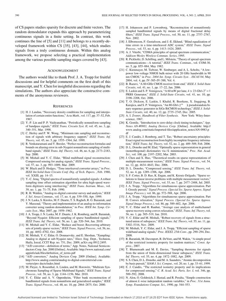
390 IEEE JOURNAL OF SELECTED TOPICS IN SIGNAL PROCESSING, VOL. 4, NO. 2, APRIL 2010
of CS papers studies sparsity for discrete and finite vectors. Therandom demodulator expands this approach by parameterizingcontinuous signals in a finite setting. In contrast, this workcontinues the line of [5] and [11] and belongs to a recently-de-veloped framework within CS [35], [43], [44], which studiessignals from a truly continuous domain. Within this analogframework, we propose selecting a practical implementationamong the various possible sampling stages covered by [43].
ACKNOWLEDGMENT
The authors would like to thank Prof. J. A. Tropp for fruitfuldiscussions and for helpful comments on the first draft of thismanuscript, and Y. Chen for insightful discussions regarding thesimulations. The authors also appreciate the constructive com-ments of the anonymous reviewers.
REFERENCES
[1] H. J. Landau, “Necessary density conditions for sampling and interpo-lation of certain entire functions,” Acta Math., vol. 117, pp. 37–52, Feb.1967.
[2] Y.-P. Lin and P. P. Vaidyanathan, “Periodically nonuniform samplingof bandpass signals,” IEEE Trans. Circuits Syst. II, vol. 45, no. 3, pp.340–351, Mar. 1998.
[3] C. Herley and P. W. Wong, “Minimum rate sampling and reconstruc-tion of signals with arbitrary frequency support,” IEEE Trans. Inf.Theory, vol. 45, no. 5, pp. 1555–1564, Jul. 1999.
[4] R. Venkataramani and Y. Bresler, “Perfect reconstruction formulas andbounds on aliasing error in sub-Nyquist nonuniform sampling of multi-band signals,” IEEE Trans. Inf. Theory, vol. 46, no. 6, pp. 2173–2183,Sep. 2000.
[5] M. Mishali and Y. C. Eldar, “Blind multiband signal reconstruction:Compressed sensing for analog signals,” IEEE Trans. Signal Process.,vol. 57, no. 3, pp. 993–1009, Mar. 2009.
[6] W. Black and D. Hodges, “Time interleaved converter arrays,” in Proc.IEEE Int.Solid-State Circuits Conf. Dig. of Tech. Papers. , Feb. 1980,vol. XXIII, pp. 14–15.
[7] Y.-C. Jenq, “Digital spectra of nonuniformly sampled signals: A robustsampling time offset estimation algorithm for ultra high-speed wave-form digitizers using interleaving,” IEEE Trans. Instrum. Meas., vol.39, no. 1, pp. 71–75, Feb. 1990.
[8] R. H. Walden, “Analog-to-digital converter survey and analysis,” IEEEJ. Sel. Areas Commun., vol. 17, no. 4, pp. 539–550, Apr. 1999.
[9] J. N. Laska, S. Kirolos, M. F. Duarte, T. S. Ragheb, R. G. Baraniuk, andY. Massoud, “Theory and implementation of an analog-to-informationconverter using random demodulation,” in Proc. IEEE Int. Symp. Cir-cuits Syst., May 2007, pp. 1959–1962.
[10] J. A. Tropp, J. N. Laska, M. F. Duarte, J. K. Romberg, and R. Baraniuk,“Beyond Nyquist: Efficient sampling of sparse bandlimited signals,”IEEE Trans. Inf. Theory, vol. 56, no. 1, pp. 520–544, Jan. 2010.
[11] M. Mishali and Y. C. Eldar, “Reduce and boost: Recovering arbitrarysets of jointly sparse vectors,” IEEE Trans. Signal Process., vol. 56, no.10, pp. 4692–4702, Oct. 2008.
[12] M. Mishali, Y. C. Eldar, O. Dounaevsky, and E. Shoshan, “Xampling:Analog to digital at sub-Nyquist rates,” Elect. Eng. Dept., Technion,Haifa, Isreal, CCIT Rep. no. 751, Dec. 2009, arXiv.org 0912.2495.
[13] “A/D converter—definition of terms,” App. Notes, National Semicon-ductors Corp. Jan. 2000 [Online]. Available: http://www.national.com/appinfo/adc/files/definition_of_terms.pdf
[14] “A/D converters,” Analog Devices Corp. 2009 [Online]. Available:http://www.analog.com/en/analog-to-digital-converters/ad-con-verters/pro ducts/index.html
[15] M. Fleyer, A. Rosenthal, A. Linden, and M. Horowitz, “Multirate Syn-chronous Sampling of Sparse Multiband Signals,” IEEE Trans. SignalProcess., vol. 58, no. 3, pp. 1144–1156, Mar. 2010.
[16] Y. C. Eldar and A. V. Oppenheim, “Filter bank reconstruction ofbandlimited signals from nonuniform and generalized samples,” IEEETrans. Signal Process., vol. 48, no. 10, pp. 2864–2875, Oct. 2000.
[17] H. Johansson and P. Lowenborg, “Reconstruction of nonuniformlysampled bandlimited signals by means of digital fractional delayfilters,” IEEE Trans. Signal Process., vol. 50, no. 11, pp. 2757–2767,Nov. 2002.
[18] J. Elbornsson, F. Gustafsson, and J.-E. Eklund, “Blind equalization oftime errors in a time-interleaved ADC system,” IEEE Trans. SignalProcess., vol. 53, no. 4, pp. 1413–1424, 2005.
[19] A. J. Viterbi, “CDMA principles of spread spectrum communication,”Addison-Wesley Wireless Commun. Series, 1995.
[20] R. Pickholtz, D. Schilling, and L. Milstein, “Theory of spread-spectrumcommunications—A tutorial,” IEEE Trans. Commun., vol. COM-30,no. 5, pp. 855–884, May 1982.
[21] C. Kienmayer, M. Tiebout, W. Simburger, and A. L. Scholtz, “A low-power low-voltage NMOS bulk-mixer with 20 GHz bandwidth in 90nm CMOS,” in Proc. 2004 Int. Symp. Circuits Syst. . ISCAS’04, May2004, vol. 4, pp. IV-385–IV-388, Vol. 4.
[22] B. Razavi, “A 60-GHz CMOS receiver front-end,” IEEE J. Solid-StateCircuits, vol. 41, no. 1, pp. 17–22, Jan. 2006.
[23] E. Laskin and S. P. Voinigescu, “A 60 mW per lane, 4� 23-Gb/s 2 ��PRBS Generator,” IEEE J. Solid-State Circuits, vol. 41, no. 10, pp.2198–2208, Oct. 2006.
[24] T. O. Dickson, E. Laskin, I. Khalid, R. Beerkens, X. Jingqiong, B.Karajica, and S. P. Voinigescu, “An 80-Gb/s � �� pseudorandom bi-nary sequence generator in SiGe BiCMOS technology,” IEEE J. Solid-State Circuits, vol. 40, no. 12, pp. 2735–2745, Dec. 2005.
[25] A. I. Zverev, Handbook of Filter Synthesis. New York: Wiley-Inter-science, 1967.
[26] K. Gentile, “Introduction to zero-delay clock timing techniques,” App.Notes AN-#0983, Analog Devices Corp. [Online]. Available: http://www.analog.com/static/imported-files/application_notes/AN-0983.pdf
[27] E. J. Candès, J. Romberg, and T. Tao, “Robust uncertainty principles:Exact signal reconstruction from highly incomplete frequency informa-tion,” IEEE Trans. Inf. Theory, vol. 52, no. 2, pp. 489–509, Feb. 2006.
[28] D. L. Donoho and M. Elad, “Optimally sparse representation in general(nonorthogonal) dictionaries via �� minimization,” Proc. Nat. Acad.Sci., vol. 100, pp. 2197–2202, Mar. 2003.
[29] J. Chen and X. Huo, “Theoretical results on sparse representations ofmultiple-measurement vectors,” IEEE Trans. Signal Process., vol. 54,no. 12, pp. 4634–4643, Dec. 2006.
[30] D. L. Donoho, “Compressed sensing,” IEEE Trans. Inf. Theory, vol.52, no. 4, pp. 1289–1306, Apr. 2006.
[31] S. F. Cotter, B. D. Rao, K. Engan, and K. Kreutz-Delgado, “Sparse so-lutions to linear inverse problems with multiple measurement vectors,”IEEE Trans. Signal Process., vol. 53, no. 7, pp. 2477–2488, Jul. 2005.
[32] J. A. Tropp, “Algorithms for simultaneous sparse approximation. PartI: Greedy pursuit,” Signal Process. (Special Iss. Sparse Approx. SignalImage Process.), vol. 86, pp. 572–588, Apr. 2006.
[33] J. A. Tropp, “Algorithms for simultaneous sparse approximation. PartII: Convex relaxation,” Signal Process. (Special Iss. Sparse Approx.Signal Image Process.), vol. 86, pp. 589–602, Apr. 2006.
[34] Y. C. Eldar and H. Rauhut, “Average case analysis of multichannelsparse recovery using convex relaxation,” IEEE. Trans. Inf. Theory, vol.56, no. 1, pp. 505–519, Jan. 2010.
[35] Y. C. Eldar and M. Mishali, “Robust recovery of signals from a struc-tured union of subspaces,” IEEE Trans. Inf. Theory, vol. 55, no. 11, pp.5302–5316, Nov. 2009.
[36] M. Mishali, Y. C. Eldar, and J. A. Tropp, “Efficient sampling of sparsewideband analog signals,” Proc. IEEEI, 25th Conv., pp. 290–294, Dec.2008.
[37] R. Baraniuk, M. Davenport, R. DeVore, and M. Wakin, “A simple proofof the restricted isometry property for random matrices,” Const. Ap-prox., 2007.
[38] T. Blumensath and M. E. Davies, “Sampling theorems for signalsfrom the union of finite-dimensional linear subspaces,” IEEE Trans.Inf. Theory, vol. 55, no. 4, pp. 1872–1882, Apr. 2009.
[39] S. S. Chen, D. L. Donoho, and M. A. Saunders, “Atomic decompositionby basis pursuit,” SIAM J. Sci. Comput., vol. 20, no. 1, pp. 33–61, 1999.
[40] E. J. Candès, “The restricted isometry property and its implicationsfor compressed sensing,” C. R. Acad. Sci. Paris, Ser. I, vol. 346, pp.589–592, 2008.
[41] N. Alon, O. Goldreich, J. Hastad, and R. Peralta, “Simple constructionof almost �-wise independent random variables,” in Proc. 31st Annu.Symp. Foundations Comput. Sci., 1990, pp. 544–553.
Authorized licensed use limited to: Technion Israel School of Technology. Downloaded on March 17,2010 at 07:16:25 EDT from IEEE Xplore. Restrictions apply.
MISHALI AND ELDAR: FROM THEORY TO PRACTICE: SUB-NYQUIST SAMPLING OF SPARSE WIDEBAND ANALOG SIGNALS 391
[42] M. Mishali, Y. C. Eldar, and A. Elron, “Xampling. Part I: Practice,”Elect. Eng. Dept., Technion, CCIT Rep. no. 747, arXiv.org 0911.0519,Oct. 2009.
[43] Y. C. Eldar, “Compressed sensing of analog signals in shift-invariantspaces,” IEEE Trans. Signal Process., vol. 57, no. 8, pp. 2986–2997,Aug. 2009.
[44] Y. C. Eldar, “Uncertainty relations for shift-invariant analog signals,”IEEE Trans. Inf. Theory, vol. 55, no. 12, pp. 5742–5757, Dec.. 2009.
Moshe Mishali (S’08) received the B.Sc. degree inelectrical engineering (summa cum laude) from theTechnion—Israel Institute of Technology, Haifa, in2000, where he is currently pursuing the Ph.D. degreein electrical engineering.
From 1996 to 2000, he was a member of theTechnion Program for Exceptionally Gifted Stu-dents. Since 2006, he has been a Research Assistantand Project Supervisor with the Signal and ImageProcessing Lab, Electrical Engineering Department,Technion. His research interests include theoretical
aspects of signal processing, compressed sensing, sampling theory, and infor-mation theory.
Mr. Mishali received the Hershel Rich Innovation Award in 2008.
Yonina C. Eldar (S’97–M’02–SM’07) received theB.Sc. degree in physics and the B.Sc. degree in elec-trical engineering from Tel-Aviv University (TAU),Tel-Aviv, Israel, in 1995 and 1996, respectively,and the Ph.D. degree in electrical engineering andcomputer science from the Massachusetts Instituteof Technology (MIT), Cambridge, in 2001.
From January 2002 to July 2002 she was aPostdoctoral Fellow at the Digital Signal ProcessingGroup at MIT. She is currently a Professor in theDepartment of Electrical Engineering at the Tech-
nion—Israel Institute of Technology, Haifa. She is also a Research Affiliatewith the Research Laboratory of Electronics at MIT.
Dr. Eldar was in the program for outstanding students at TAU from 1992 to1996. In 1998, she held the Rosenblith Fellowship for study in Electrical Engi-neering at MIT, and in 2000, she held an IBM Research Fellowship. From 2002to 2005, she was a Horev Fellow of the Leaders in Science and Technologyprogram at the Technion and an Alon Fellow. In 2004, she was awarded theWolf Foundation Krill Prize for Excellence in Scientific Research, in 2005 theAndre and Bella Meyer Lectureship, in 2007 the Henry Taub Prize for Excel-lence in Research, in 2008 the Hershel Rich Innovation Award, the Award forWomen with Distinguished Contributions, the Muriel & David Jacknow Awardfor Excellence in Teaching, and the Technion Outstanding Lecture Award, andin 2009 the Technion’s Award for excellence in teaching. She is a member ofthe IEEE Signal Processing Theory and Methods technical committee and theBio Imaging Signal Processing technical committee, an Associate Editor for theIEEE TRANSACTIONS ON SIGNAL PROCESSING, the EURASIP Journal of SignalProcessing, and the SIAM Journal on Matrix Analysis and Applications, and onthe Editorial Board of Foundations and Trends in Signal Processing.
Authorized licensed use limited to: Technion Israel School of Technology. Downloaded on March 17,2010 at 07:16:25 EDT from IEEE Xplore. Restrictions apply.