IEEE JOURNAL OF SELECTED TOPICS IN SIGNAL PROCESSING (TO APPEAR) 1
14
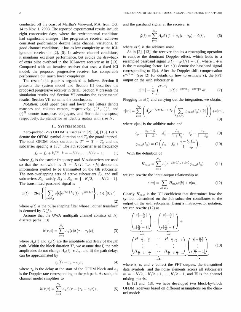
IEEE JOURNAL OF SELECTED TOPICS IN SIGNAL PROCESSING (TO APPEAR) 1 Progressive Inter-carrier Interference Equalization for OFDM Transmission over Time-varying Underwater Acoustic Channels Jianzhong Huang, Student Member, IEEE, Shengli Zhou, Member, IEEE, Jie Huang, Christian R. Berger, Member, IEEE, and Peter Willett, Fellow, IEEE Abstract—Multicarrier modulation in the form of orthogonal- frequency-division-multiplexing (OFDM) has been intensively pursued for underwater acoustic (UWA) communications recently due to its ability to handle long dispersive channels. Fast variation of UWA channels destroys the orthogonality of the sub-carriers and leads to inter-carrier interference (ICI), which degrades the system performance significantly. In this paper we propose a progressive receiver dealing with time-varying UWA channels. The progressive receiver is in nature an iterative receiver, based on the turbo principle. However, it distinguishes itself from existing iterative receivers in that the system model for channel estimation and data detection is itself continually updated during the iterations. When the decoding in the current iteration is not successful, the receiver increases the span of the ICI in the system model and utilizes the currently available soft information from the decoder to assist the next iteration which deals with a channel with larger Doppler spread. Numerical simulation and experimental data collected from the 2008 Surface Processes and Acoustic Communications Experiment (SPACE08) show that the proposed receiver can self adapt to channel variations, enjoying low complexity in good channel conditions while maintaining excellent performance in adverse channel conditions. Index Terms—Turbo equalization, iterative receiver, sparse channel estimation, OFDM, inter-carrier interference, underwa- ter acoustic communications. I. I NTRODUCTION Recently, multicarrier modulation in the form of orthogonal- frequency-division-multiplexing (OFDM) has been actively pursued for underwater acoustic communications; see per- formance results based on data recorded from various field experiments in [2]–[13]. Different receivers are built based on different assumptions on the underlying channel models. Specifically, the receivers in [2]–[10] assume that inter-carrier interference (ICI) can be neglected after proper resampling Manuscript submitted January 6, 2011, revised May 21, 2011, accepted June 10, 2011. This work was supported by the ONR grants N00014-07-1-0805 (YIP), N00014-09-1-0704 (PECASE) and the NSF grant CNS-0721834. This work was presented in part at the MTS/IEEE OCEANS conference, Sydney, Australia, May 24-27, 2010 [1]. The associate editor coordinating the review of this manuscript and approving it for publication was Dr. Geert Leus. Copyright c 2008 IEEE. Personal use of this material is permitted. How- ever, permission to use this material for any other purposes must be obtained from the IEEE by sending a request to [email protected]. J.-Z. Huang, S. Zhou, J. Huang and P. Willett are with the Department of Electrical and Computer Engineering, University of Connecticut, Storrs, CT 06269, USA (e-mail: {jianzhong, shengli, jhuang, willett}@engr.uconn.edu). C. R. Berger is with the Department of Electrical and Computer Engi- neering, Carnegie Mellon University, Pittsburgh, PA 15213, USA (e-mail: [email protected]). Digital Object Identifier 00.0000/JSTSP.2011.0000000 and Doppler shift compensation, while the receivers in [11]– [13] explicitly deal with ICI. Ignoring the ICI, the receivers in [2]–[9] have low complexity on channel estimation and data detection, however, their performance degrades quickly in channels with large Doppler spread. Explicitly accounting for the ICI, the receiver in [13] achieves robust performance even in very challenging channel conditions. However, it requires a significant pilot overhead for channel estimation, and the receiver complexity is considerably higher than its ICI-ignorant counterparts [16]. In practice, underwater acoustic (UWA) channels are rapidly time-varying due to environmental variations such as wind speed, wave height, and the motion of the transceiver plat- forms. So far, there is no commonly-agreed model for UWA channels. One important area of research is to investigate how environmental factors affect the performance of a particular receiver structure, see e.g., [17], [18]. In this paper, we propose an OFDM receiver that can adapt to different channel conditions in an automatic fashion. By its nature, the proposed progressive receiver is an iterative receiver, following the turbo principle. However, it distin- guishes itself from existing iterative receivers, e.g., [19]–[25], in that the system model itself for channel estimation and data detection keeps being updated during the iterations. When the decoding in the current iteration is not successful, the receiver increases the span of the ICI in the system model and utilizes the available soft information from the channel decoder to deal with a channel with a larger Doppler spread in the next iteration. For channel estimation, we use basis pursuit algorithms developed in the compressed sensing context to exploit the sparse nature of UWA channels [13], where we also in- corporate the soft information from the decoder. The ICI mitigation problem in the frequency-domain is equivalent to that of intersymbol interference (ISI) equalization in the time- domain, but with time-varying ISI coefficients. Hence, existing methods for ISI equalization can be directly used for ICI mitigation. In this paper, we adopt the maximum a posteriori (MAP) equalizer from [26], the minimum-mean-squared-error (MMSE) equalizer from [19]–[21], and the Markov Chain Monte Carlo (MCMC) equalizer from [27]–[29], all of which can effectively utilize a priori information for data detection. We conduct extensive tests on the progressive receiver using both simulations and experimental data from the Surface Pro- cesses and Acoustic Communications Experiment (SPACE08),
Transcript of IEEE JOURNAL OF SELECTED TOPICS IN SIGNAL PROCESSING (TO APPEAR) 1
IEEE JOURNAL OF SELECTED TOPICS IN SIGNAL PROCESSING (TO APPEAR) 1
Progressive Inter-carrier Interference Equalizationfor OFDM Transmission over Time-varying
Underwater Acoustic ChannelsJianzhong Huang,Student Member, IEEE, Shengli Zhou,Member, IEEE, Jie Huang,
Christian R. Berger,Member, IEEE, and Peter Willett,Fellow, IEEE
Abstract—Multicarrier modulation in the form of orthogonal-frequency-division-multiplexing (OFDM) has been intensivelypursued for underwater acoustic (UWA) communications recentlydue to its ability to handle long dispersive channels. Fast variationof UWA channels destroys the orthogonality of the sub-carriersand leads to inter-carrier interference (ICI), which degrades thesystem performance significantly. In this paper we propose aprogressive receiver dealing with time-varying UWA channels.The progressive receiver is in nature an iterative receiver, basedon the turbo principle. However, it distinguishes itself fromexisting iterative receivers in that the system model for channelestimation and data detection is itself continually updated duringthe iterations. When the decoding in the current iteration isnot successful, the receiver increases the span of the ICI inthesystem model and utilizes the currently available soft informationfrom the decoder to assist the next iteration which deals with achannel with larger Doppler spread. Numerical simulation andexperimental data collected from the2008 Surface Processes andAcoustic Communications Experiment (SPACE08) show that theproposed receiver can self adapt to channel variations, enjoyinglow complexity in good channel conditions while maintainingexcellent performance in adverse channel conditions.
Index Terms—Turbo equalization, iterative receiver, sparsechannel estimation, OFDM, inter-carrier interference, underwa-ter acoustic communications.
I. I NTRODUCTION
Recently, multicarrier modulation in the form of orthogonal-frequency-division-multiplexing (OFDM) has been activelypursued for underwater acoustic communications; see per-formance results based on data recorded from various fieldexperiments in [2]–[13]. Different receivers are built basedon different assumptions on the underlying channel models.Specifically, the receivers in [2]–[10] assume that inter-carrierinterference (ICI) can be neglected after proper resampling
Manuscript submitted January 6, 2011, revised May 21, 2011,accepted June10, 2011. This work was supported by the ONR grants N00014-07-1-0805(YIP), N00014-09-1-0704 (PECASE) and the NSF grant CNS-0721834. Thiswork was presented in part at the MTS/IEEE OCEANS conference, Sydney,Australia, May 24-27, 2010 [1]. The associate editor coordinating the reviewof this manuscript and approving it for publication was Dr. Geert Leus.
Copyright c©2008 IEEE. Personal use of this material is permitted. How-ever, permission to use this material for any other purposesmust be obtainedfrom the IEEE by sending a request to [email protected].
J.-Z. Huang, S. Zhou, J. Huang and P. Willett are with the Department ofElectrical and Computer Engineering, University of Connecticut, Storrs, CT06269, USA (e-mail:jianzhong, shengli, jhuang, [email protected]).
C. R. Berger is with the Department of Electrical and Computer Engi-neering, Carnegie Mellon University, Pittsburgh, PA 15213, USA (e-mail:[email protected]).
Digital Object Identifier 00.0000/JSTSP.2011.0000000
and Doppler shift compensation, while the receivers in [11]–[13] explicitly deal with ICI. Ignoring the ICI, the receiversin [2]–[9] have low complexity on channel estimation anddata detection, however, their performance degrades quicklyin channels with large Doppler spread. Explicitly accountingfor the ICI, the receiver in [13] achieves robust performanceeven in very challenging channel conditions. However, itrequires a significant pilot overhead for channel estimation,and the receiver complexity is considerably higher than itsICI-ignorant counterparts [16].
In practice, underwater acoustic (UWA) channels are rapidlytime-varying due to environmental variations such as windspeed, wave height, and the motion of the transceiver plat-forms. So far, there is no commonly-agreed model for UWAchannels. One important area of research is to investigate howenvironmental factors affect the performance of a particularreceiver structure, see e.g., [17], [18].
In this paper, we propose an OFDM receiver that can adaptto different channel conditions in an automatic fashion. Byits nature, the proposed progressive receiver is an iterativereceiver, following the turbo principle. However, it distin-guishes itself from existing iterative receivers, e.g., [19]–[25],in that the system model itself for channel estimation and datadetection keeps being updated during the iterations. When thedecoding in the current iteration is not successful, the receiverincreases the span of the ICI in the system model and utilizesthe available soft information from the channel decoder todeal with a channel with a larger Doppler spread in the nextiteration.
For channel estimation, we use basis pursuit algorithmsdeveloped in the compressed sensing context to exploit thesparse nature of UWA channels [13], where we also in-corporate the soft information from the decoder. The ICImitigation problem in the frequency-domain is equivalent tothat of intersymbol interference (ISI) equalization in thetime-domain, but with time-varying ISI coefficients. Hence, existingmethods for ISI equalization can be directly used for ICImitigation. In this paper, we adopt the maximuma posteriori(MAP) equalizer from [26], the minimum-mean-squared-error(MMSE) equalizer from [19]–[21], and the Markov ChainMonte Carlo (MCMC) equalizer from [27]–[29], all of whichcan effectively utilizea priori information for data detection.
We conduct extensive tests on the progressive receiver usingboth simulations and experimental data from the Surface Pro-cesses and Acoustic Communications Experiment (SPACE08),
2 IEEE JOURNAL OF SELECTED TOPICS IN SIGNAL PROCESSING (TO APPEAR)
conducted off the coast of Martha’s Vineyard, MA, from Oct.14 to Nov. 1, 2008. The reported experimental results includeeight consecutive days, where the environmental conditionshad significant changes. The progressive receiver achievesconsistent performance despite large channel variations.Ingood channel conditions, it has as low complexity as the ICI-ignorant receiver in [2], [5]. In adverse channel conditions,it maintains excellent performance, but avoids the drawbackof extra pilot overhead in the ICI-aware receiver as in [13].Compared with an iterative receiver that uses a fixed ICImodel, the proposed progressive receiver has comparableperformance but much lower complexity.
The rest of this paper is organized as follows. Section IIpresents the system model and Section III describes theproposed progressive receiver in detail. Section V presents thesimulation results and Section VI contains the experimentalresults. Section VII contains the conclusions.
Notation: Bold upper case and lower case letters denotematrices and column vectors, respectively;(·)T , (·)∗, and(·)H denote transpose, conjugate, and Hermitian transpose,respectively.IN stands for an identity matrix with sizeN .
II. SYSTEM MODEL
Zero-padded (ZP) OFDM is used as in [2], [3], [13]. LetTdenote the OFDM symbol duration andTg the guard interval.The total OFDM block duration isT ′ = T + Tg and thesubcarrier spacing is1/T . Thekth subcarrier is at frequency
fk = fc + k/T, k = −K/2, . . . , K/2 − 1, (1)
wherefc is the carrier frequency andK subcarriers are usedso that the bandwidth isB = K/T . Let s[k] denote theinformation symbol to be transmitted on thekth subcarrier.The non-overlapping sets of active subcarriersSA and nullsubcarriersSN satisfy SA ∪ SN = −K/2, · · · , K/2 − 1.The transmitted passband signal is
x(t) = 2Re
[∑
k∈SA
s[k]ej2π kT
tg(t)
]
ej2πfct
, t ∈ [0, T ′]
(2)whereg(t) is the pulse shaping filter whose Fourier transformis denoted byG(f).
Assume that the UWA multipath channel consists ofNp
discrete paths [13]
h(τ, t) =
Np∑
p=1
Ap(t)δ (τ − τp(t)) (3)
whereAp(t) andτp(t) are the amplitude and delay of thepthpath. Within the block durationT ′, we assume that i) the pathamplitudes do not changeAp(t) ≈ Ap, and ii) the path delayscan be approximated by
τp(t) = τp − apt, (4)
whereτp is the delay at the start of the OFDM block andap
is the Doppler rate corresponding to thepth path. As such, thechannel model simplifies to
h(τ, t) =
Np∑
p=1
Apδ (τ − (τp − apt)) , (5)
and the passband signal at the receiver is
y(t) =
Np∑
p=1
Apx ((1 + ap)t − τp) + v(t), (6)
wherev(t) is the additive noise.As in [2], [13], the receiver applies a resampling operation
to remove the dominant Doppler effect, which leads to aresampled passband signalz(t) = y(t/(1 + a)), where1 + ais the resampling factor. Letz(t) denote the baseband signalcorresponding toz(t). After the Doppler shift compensatione−j2πεt (see [2] for details on how to estimateε), the FFToutput on themth subcarrier is
z[m] =1
T
∫ T+Tg
0
z(t)e−j2πεte−j2π mT
t dt. (7)
Plugging inz(t) and carrying out the integration, we obtain:
z[m] =
Np∑
p=1
(
A′
pe−j2π(fm+ε)τ
′
p
(∑
k∈SA
%m,k(bp)s[k]
))
+v[m],
(8)wherev[m] is the additive noise and
bp =ap − a
1 + a, A
′
p =Ap
1 + bp, τ
′
p =τp
1 + bp, (9)
%m,k(bp) = G
(
fm − fk +ε − bpfm
1 + bp
)
. (10)
With the definition of
Hm,k =
Np∑
p=1
A′
pe−j2π(fm+ε)τ ′
p%m,k(bp) (11)
we can rewrite the input-output relationship as
z[m] =∑
k∈SA
Hm,ks[k] + v[m]. (12)
Clearly Hm,k is the ICI coefficient that determines how thesymbol transmitted on thekth subcarrier contributes to theoutput on themth subcarrier. Using a matrix-vector notation,we can rewrite (12) as
z[−K2 ]
...z[K
2 − 1]
︸ ︷︷ ︸
:=z
=
v[−K2 ]
...v[K
2 − 1]
︸ ︷︷ ︸
:=v
+
H−K2
,−K2
· · · H−K2
, K2−1
.... . .
...HK
2−1,−K
2
· · · HK2−1, K
2−1
︸ ︷︷ ︸
:=H
s[−K2 ]
...s[K
2 − 1]
︸ ︷︷ ︸
:=s
(13)
where z, s, and v collect the FFT outputs, the transmitteddata symbols, and the noise elements across all subcarriersm = −K/2,−K/2 + 1, . . . , K/2 − 1, andH is the channelmixing matrix.
In [2] and [13], we have developed two block-by-blockOFDM receivers based on different assumptions on the chan-nel model:

HUANG et al.: PROGRESSIVE INTER-CARRIER INTERFERENCE EQUALIZATION FOR OFDM TRANSMISSION OVER TIME-VARYING UWA CHANNELS 3
• ICI-ignorant receiver [2]: It is assumed that all the pathshave a similar Doppler rateap = a, ∀p, and hence the ICIcan be ignored after proper resampling and Doppler shiftcompensation. As such, the channel mixing matrixH isdiagonal, leading to low-complexity channel estimationand data demodulation. The experimental results in [2],[13] show that the ICI-ignorant receiver works well ingood channel conditions, but its performance degradesconsiderably at adverse channel conditions.
• ICI-aware receiver [13]: It is assumed that all the pathshave different Doppler rates, and hence ICI exists andis explicitly dealt with by the receiver. The ICI-awarereceiver achieves excellent performance even in adversechannel conditions. However, a large number of pilots isneeded for channel estimation, which reduces the spectralefficiency. Also, the complexity is much higher than thatof ICI-ignorant receivers.
In this paper, we develop a progressive receiver structurethat can adapt itself to channel conditions. It will have aslow complexity as the ICI-ignorant receiver in good channelconditions, while achieving as excellent performance as theICI-aware receiver in adverse channel conditions. Furthermorethe progressive receiver does not require any extra pilotoverhead, compared to the non-iterative receiver in [13].
III. R ECEIVER STRUCTURE
We first present the overview of the proposed receiverstructure in Section III-A, and then specify the key modulesin Sections III-B – III-E.
A. The Progressive Receiver Structure
The proposed progressive receiver is an iterative receiverin nature, following the turbo principle. However, in contrastto existing iterative receivers in the literature, the systemmodel used for channel identification and data demodulationchanges at each iteration. It starts with a simple channelmodel that allows for ICI-ignorant receiver processing, andthen progresses to ICI-aware receiver processing where theseverity of the assumed ICI increases as the iteration goeson. The soft information obtained from the previous iterationcontributes to channel estimation and data demodulation forthe current iteration. This way, the receiver can self adaptto the “unknown” degree of channel variation progressively.The proposed receiver keeps the complexity low when thechannel conditions are good, while still maintaining excellentperformance when the channel conditions deteriorate.
The channel models used in the proposed receiver structureare parameterized by a parameterD as
Hm,k ' 0, |m − k| > D. (14)
In other words, each symbol only affects itsD direct neighborson each side, a reasonable assumption used in many existingworks, e.g., [11], [22], [24], [30]. In this paper, we termD asthe ICI depth and2D +1 as the ICI span. LetHD denote thematrix carved fromH keeping only the main diagonal and2D
H0 H1
H2 H3
z
..
.
..
...
.
..
..
..
..
...
.
..
...
.
..
...
.
..
...
.
..
.
= + ns
Fig. 1. The equivalent system model with different ICI spans.
off-diagonals, as shown in Fig. 1. The effective system modelused for channel estimation and data demodulation is:
z = HDs + (H − HD)s + v
= HDs + n, (15)
where n := (H − HD)s + v is the effective noise. In theproposed progressive receiver, the parameterD increases asthe iteration goes on, and hence more severe ICI can beaddressed as the receiver processing proceeds to deal withchannels with large Doppler spread.
Fig. 2 depicts the progressive receiver structure, whichconsists of the following steps.
• Step 1: Pre-processing. For each received OFDM block,the receiver applies the pre-processing operation to re-move the dominant Doppler effect [2]. SetD = 0.
• Step 2: Channel estimation. Estimate the equivalent chan-nel mixing matrix HD based on the assumed channelmodel given in (15).
• Step 3: Noise variance estimation. After channel estima-tion, the variance of the effective noisen is computed.This quantity is needed for ICI equalization.
• Step 4: ICI equalization. By using the estimated channelmatrixHD, the equivalent noise variance, and thea prioriinformation from the nonbinary LDPC decoder in theprevious iteration, the ICI equalizer generates soft outputon the reliability of the data symbols.
• Step 5: Nonbinary LDPC decoding. The nonbinary LDPCdecoder yields the decoded information symbols and thesoft information that can be used for channel estimationand ICI equalization [5]. During the decoding process,the decoder will declare success if all the parity checkconditions are satisfied.
• Step 6: Iteration among steps 2 to 5. IncreaseD inthe system model, and the assumed maximum Dopplerspread of the channel to be estimated. Feed back thesoft information to the channel estimator and the ICIequalizer. Iteration stops when the decoder declares asuccess, or whenD reaches a pre-specified numberDmax.
In the proposed receiver as depicted in Fig. 2, each iterationis associated with a differentD. The receiver can also iteratemultiple times among step 2 to step 5 on channel estimation,equalization and decoding for each fixedD, before increasing

4 IEEE JOURNAL OF SELECTED TOPICS IN SIGNAL PROCESSING (TO APPEAR)
Nosuccess or
D = Dmax
Yes
Output
decisions
Nonbinary
LDPC decoding
ICI equalization
Noise variance
estimation
Channel estimation
Increase D;
provide soft
information
Pre-processing;
set D = 0
z = HDs + n
Fig. 2. Progressive receiver structure.
D to update the system model. Here we skip such a possibilityfor simplicity. Note that we have extended the progressive re-ceiver structure to a multi-input multi-output (MIMO) systemin [38], where multiple iterations among channel estimation,equalization and decoding are explicitly used for each systemmodel with a particularD.
B. Sparse Channel Estimation
The inputs to the channel estimator are the observationsin z, the pilot symbols, and thea posteriori probabilities(APP) of the information symbols from the nonbinary LDPCdecoder. Different strategies on how to use APP can be foundin [9]. Here, we use the soft feedback strategy, which producesMMSE estimates of the information symbols as
s[k] =
M∑
i=1
Papp(s[k] = αi)αi, ∀ k ∈ SD (16)
whereM is the constellation size,αi is the ith constellationpoint, Papp(·) is the APP from LDPC decoder, andSD is theset of data subcarriers inSA. Hence, an estimate ofs (denotedby s) can be formed from
s[k] =
s[k], k ∈ SP ,0, k ∈ SN ,s[k], k ∈ SD,
(17)
whereSP is the set of pilot subcarriers fromSA (SP ∪SD =SA).
Despite havingK(2D + 1) non-zero entries, the matrixHD is determined byNp triplets of (A′
p, bp, τ′p) as described
in (11). Hence, instead of estimating the full channel matrixdirectly, we estimate the parameters ofNp channel paths.For sparse UWA channels [13], it is possible that theseNp
paths can be identified based on only a limited number ofmeasurements via advanced methods, such as compressedsensing. We will use the basis pursuit algorithms developedin the compressed sensing context as the building block [13].
The compressed sensing based channel estimator tries toidentify the discrete paths from an overcomplete dictionary[13]. In particular, let us split the delay/Doppler ranges(τ ′, b)into a large number of dictionaries, and then connect thecomplex channel amplitudes with the frequency domain ob-servations through the constructed dictionaries. On the delayand Doppler plane, a set of uniformly spaced points can beconstructed from
τ ′ ∈
0,T
λK,
2T
λK, . . . ,
(Nτ − 1)T
λK
, (18)
bD ∈−bD
max,−bDmax + ∆b, . . . , bD
max
, (19)
where the time resolution is chosen as a fraction,λ, of thebaseband sampling timeT/K, leading toNτ = λKTg/Ttentative delays. For the Doppler rates, we assume that theyare spread around zero after pre-processing, and∆b is theDoppler resolution.bD
max can be chosen based on the assumedDoppler spread for the current system model. There are
2bDmax/(∆b) + 1 = ND
b , (20)
tentative Doppler rates, leading to a delay-Doppler dictio-nary of sizeNτND
b . During the iterations, the progressivereceiver keeps the delay dictionary unchanged, but enlargesthe Doppler dictionary size by increasingbD
max asD increases.This way, channels with large Doppler spread can be ad-dressed.
Let ξl,i be the complex coefficient for a possible path thathas delayτ ′
l and Doppler scalebDi . Define a diagonal matrix
Λl with [Λl]m,m = e−j2π mT
τ ′
l . Define another matrixΓDi
having(m, k)th entry as
[ΓDi ]m,k =
%m,k(bDi ), |m − k| ≤ D,
0, otherwise,(21)
where %m,k(·) is defined in (10). Note that the DopplertemplateΓD
i is a banded matrix, corresponding toHD.Therefore, the equivalent “mixing” channel matrix con-
structed by thoseNτNDb dictionaries can be written as
HD =
NDb∑
i=1
Nτ∑
l=1
ξl,iΛlΓDi (22)
With this, the observationz can be rewritten as the combi-

HUANG et al.: PROGRESSIVE INTER-CARRIER INTERFERENCE EQUALIZATION FOR OFDM TRANSMISSION OVER TIME-VARYING UWA CHANNELS 5
nation of all possible delay/Doppler dictionaries as
z = HD s + n
=
NDb∑
i=1
Nτ∑
l=1
ξl,iΛlΓDi s + n
= [(Λ1ΓD1 s), . . . , (ΛNτ
ΓDND
bs)]
︸ ︷︷ ︸
:=A
ξ1,1
...ξNτ ,ND
b
︸ ︷︷ ︸
:=x
+n (23)
Then, channel estimation becomes a fitting problem with theconstraint that the solutionx is sparse, which can be solvedby the following convex optimization problem
minx
‖Ax − z‖2+ ζ ‖x‖1 , (24)
whereζ is the regularization parameter to control the sparsityof x.
After obtaining the sparse channel solutionx, we canreconstruct the frequency domain response according to (22).Many solvers for the formulation in (24) are available, see e.g.,[31]–[33], but it should be noted that i)x is complex, and ii)the matrixA is of large dimension, butAb andA
Tc can be
evaluated efficiently. In this paper, we use the SpaRSA algo-rithm [34], which is based on iterative shrinkage/thresholding(IST). The complexity issue is investigated in [16].
Remark 1: During the first iteration, the symbol estimatesfrom the decoder ([c.f. (24)]) are not available. Only themeasurements on the pilot subcarriers are used for channelestimation, as done in [2]. Since only the delay grid is searchedin the first iteration withD = 0, the number of measurementsneeded can be much smaller than the later iterations withD > 0.
Remark 2: We choose the sparsity factorζ in (24) as afunction of the effective signal-to-noise ratio (SNR) for eachOFDM block asζ = c/
√SNR, wherec is a constant. In
simulation and experimental results,c is set to 0.12. Theeffective SNR will be updated as the iteration goes on. Noisevariance estimation is described in Section III-C.
C. Noise Variance Estimation
WhenD increases, more ICI will be modeled as opposed tobeing treated as additive noise. The variance of the effectivenoise hence needs to be updated at each iteration. We estimatethe noise variance as
N0 = E
[∣∣∣zm −
k=D∑
k=−D
Hm,m−ks[m − k]∣∣∣
2]
, (25)
where the expectation is carried out on the null subcarriersinSN that are within the signal band. ForD = 0, all the ICIterms are treated as additive noise, andN0 in (25) measuresthe energy on the null subcarriers [2]. As less ICI is viewedas additive noise, the effective signal-to-noise ratio (SNR) isexpected to increase.
A simple noise-whitening approach as in [10] will be usedwhen D = 0, as the effective noise may not be independentof the desired signal and ICI is the dominant source for the
noise. As the iteration goes on withD > 0, the spillover fromthe neighboring subcarriers to the null subcarriers is extractedas in (25), and no whitening is applied.
D. ICI Equalization
After obtaining the estimated channel matrixHD, thereceiver now deals with ICI mitigation, based on the observa-tions in z and the soft information (denoted byλe) fed backfrom the nonbinary LDPC decoder.
Based on (15), the observation on themth subcarrier canbe written as
z[m] =
k=D∑
k=−D
Hm,m−ks[m − k] + n[m], (26)
which is in the convolution form but with coefficients that arechanging from symbol to symbol. Hence, the ICI mitigationproblem in the frequency domain is equivalent to an inter-symbol-interference (ISI) equalization problem in the timedomain with time-varying channel taps. Existing methods forISI equalization can be used for ICI equalization. Here we con-sider the MAP equalizer [26], the MMSE equalizer from [19],[20], and the Markov Chain Monte Carlo (MCMC) equalizerfrom [27]–[29], all of which can effectively incorporate softinformation from the channel decoder.
1) MAP Equalizer: In our system with nonbinary LDPCcodes, the size of the Galois field is matched to the con-stellation size, with each element in the finite field directlymapped to a constellation point [5]. Thea posterior log-likelihood-ratio vector (LLRV) fors[m] is defined asλ[m] =[λ0[m], λ1[m], . . . , λM−1[m]]
T , whereM is the constellationsize and
λi[m] = lnP (s[m] = αi|z, λe)
P (s[m] = 0|z, λe)
= ln
∑
s:s[m]=αi
P (z|s, λe)P (s|λe)
∑
s:s[m]=0
P (z|s, λe)P (s|λe)
= ln
∑
s:s[m]=αi
P (z|s)P (s|λe)
∑
s:s[m]=0
P (z|s)P (s|λe)(27)
The summation in the numerator and denominator of (27)are over a total ofMK−1 combinations ofs. Due to the bandedstructure ofHm, (27) can be expressed as (28), shown at thetop of the next page. Hence, the correlation length among thepostulated data sequences is reduced fromK to 2D, and thewell-known BCJR algorithm [35] can be used to evaluate (28),utilizing the ICI trellis structure.
2) MMSE Equalizer: An MMSE equalizer witha prioriinformation from [19], [20] is used here for ICI mitigation.The channel decoder feeds back the extrinsic information,denoted asλe, based on which the meanµ[k] := E(s[k])and the varianceσ2[k] := Cov(s[k], s[k]) can be calculated.
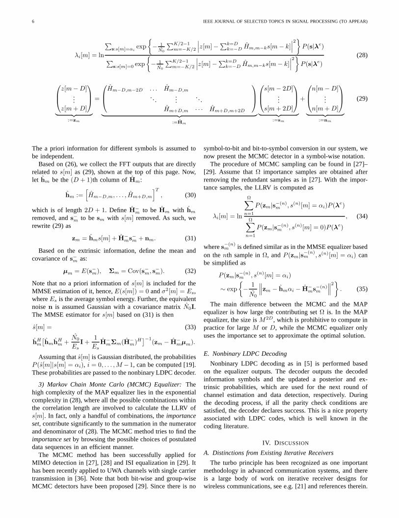
6 IEEE JOURNAL OF SELECTED TOPICS IN SIGNAL PROCESSING (TO APPEAR)
λi[m] = ln
∑
s:s[m]=αiexp
− 1N0
∑K/2−1m=−K/2
∣∣∣z[m]−∑k=D
k=−D Hm,m−ks[m − k]∣∣∣
2
P (s|λe)
∑
s:s[m]=0 exp
− 1N0
∑K/2−1m=−K/2
∣∣∣z[m] −
∑k=Dk=−D Hm,m−ks[m − k]
∣∣∣
2
P (s|λe)
(28)
z[m− D]...
z[m + D]
︸ ︷︷ ︸
:=zm
=
Hm−D,m−2D . . . Hm−D,m
. . ....
. . .
Hm+D,m · · · Hm+D,m+2D
︸ ︷︷ ︸
:=Hm
s[m − 2D]...
s[m + 2D]
︸ ︷︷ ︸
:=sm
+
n[m − D]...
n[m + D]
︸ ︷︷ ︸
:=nm
(29)
The a priori information for different symbols is assumed tobe independent.
Based on (26), we collect the FFT outputs that are directlyrelated tos[m] as (29), shown at the top of this page. Now,let hm be the(D + 1)th column ofHm:
hm :=[
Hm−D,m, . . . , Hm+D,m
]T
, (30)
which is of length2D + 1. Define H−m to be Hm with hm
removed, ands−m to be sm with s[m] removed. As such, werewrite (29) as
zm = hms[m] + H−ms
−m + nm. (31)
Based on the extrinsic information, define the mean andcovariance ofs−m as:
µm = E(s−m), Σm = Cov(s−m, s−m). (32)
Note that no a priori information ofs[m] is included for theMMSE estimation of it, hence,E(s[m]) = 0 andσ2[m] = Es,whereEs is the average symbol energy. Further, the equivalentnoisen is assumed Gaussian with a covariance matrixN0I.The MMSE estimator fors[m] based on (31) is then
s[m] = (33)
hHm
[hmh
Hm +
N0
EsI +
1
EsH
−mΣm(H−
m)H]−1
(zm − H−mµm).
Assuming thats[m] is Gaussian distributed, the probabilitiesP (s[m]|s[m] = αi), i = 0, . . . , M −1, can be computed [19].These probabilities are passed to the nonbinary LDPC decoder.
3) Markov Chain Monte Carlo (MCMC) Equalizer: Thehigh complexity of the MAP equalizer lies in the exponentialcomplexity in (28), where all the possible combinations withinthe correlation length are involved to calculate the LLRV ofs[m]. In fact, only a handful of combinations, theimportanceset, contribute significantly to the summation in the numeratorand denominator of (28). The MCMC method tries to find theimportance set by browsing the possible choices of postulateddata sequences in an efficient manner.
The MCMC method has been successfully applied forMIMO detection in [27], [28] and ISI equalization in [29]. Ithas been recently applied to UWA channels with single carriertransmission in [36]. Note that both bit-wise and group-wiseMCMC detectors have been proposed [29]. Since there is no
symbol-to-bit and bit-to-symbol conversion in our system,wenow present the MCMC detector in a symbol-wise notation.
The procedure of MCMC sampling can be found in [27]–[29]. Assume thatΩ importance samples are obtained afterremoving the redundant samples as in [27]. With the impor-tance samples, the LLRV is computed as
λi[m] = ln
Ω∑
n=1
P (zm|s−(n)m , s(n)[m] = αi)P (λe)
Ω∑
n=1
P (zm|s−(n)m , s(n)[m] = 0)P (λe)
, (34)
wheres−(n)m is defined similar as in the MMSE equalizer based
on thenth sample inΩ, andP (zm|s−(n)m , s(n)[m] = αi) can
be simplified as
P (zm|s−(n)m , s(n)[m] = αi)
∼ exp
− 1
N0
∥∥∥zm − hmαi − H
−ms
−(n)m
∥∥∥
2
. (35)
The main difference between the MCMC and the MAPequalizer is how large the contributing setΩ is. In the MAPequalizer, the size isM2D, which is prohibitive to compute inpractice for largeM or D, while the MCMC equalizer onlyuses the importance set to approximate the optimal solution.
E. Nonbinary LDPC Decoding
Nonbinary LDPC decoding as in [5] is performed basedon the equalizer outputs. The decoder outputs the decodedinformation symbols and the updated a posterior and ex-trinsic probabilities, which are used for the next round ofchannel estimation and data detection, respectively. Duringthe decoding process, if all the parity check conditions aresatisfied, the decoder declares success. This is a nice propertyassociated with LDPC codes, which is well known in thecoding literature.
IV. D ISCUSSION
A. Distinctions from Existing Iterative Receivers
The turbo principle has been recognized as one importantmethodology in advanced communication systems, and thereis a large body of work on iterative receiver designs forwireless communications, see e.g. [21] and references therein.
HUANG et al.: PROGRESSIVE INTER-CARRIER INTERFERENCE EQUALIZATION FOR OFDM TRANSMISSION OVER TIME-VARYING UWA CHANNELS 7
One significant distinction of this work is that the systemmodel keeps being updated during the iterations, while a fixedsystem model is usually assumed in existing iterative receivers[21]. This work is motivated by decoding the recorded datafrom experiments: practical underwater acoustic channelsareconstantly varying and the characteristics are largely affectedby environmental conditions, and hence a fixed model wouldnot be appropriate for all channel conditions.
B. Complexity of Channel Estimation
The complexity of sparse channel estimation in (24) de-pends on the the problem dimension. On theDth iteration,ND
b possible Doppler scaling factors are considered. For eachtentative Doppler scalebD
i , similar operations are carried outto evaluate the effects due to the path delays [16]. Hence,channel estimation complexity is approximately linear withND
b . In the problem studied in [16], the average runtime tosolve (24) withND
b = 15 tentative Doppler rates is about30 times larger than that withND
b = 1 for the ICI-ignorantreceiver. Note that the proposed receiver gradually increasesND
b during the iterations, which helps to lower the complexity.
C. Complexity of ICI Equalization
When D increases, the ICI equalization complexity in-creases at different rates for different equalizers.
• The complexity of a MAP equalizer isO(M2D), whichincreasesexponentially with D. Hence, the MAP equal-izer is only suitable for smallD and small constellationsizeM .
• The MMSE equalizer involves matrix inversion as in (33),and its complexity is cubic withD. SinceD is small,the MMSE equalizer has low complexity. Further, thecomplexity does not depend on the constellation sizeM .
• The complexity of the MCMC equalizer depends on thesample sizeΩ and the constellation sizeM . Processingthe probabilities in the log domain, the complexity ofcalculating (35) is4D2 + 5D complex multiplications(CMs) and4D2 + 5D complex additions (CAs). As thetermH
−ms
−m in (35) is the same when drawing one partic-
ular symbol, the complexity of drawing samples for eachsymbol is roughlyΩ(M(3D+1)+2D(2D+1)) CMs andΩ(M(5D+2)+4D2) CAs. Computing the output LLRVsas in (34) needsΩ(M(3D +1)+2D(2D+1)) CMs andΩ(M(5D+2)+4D2) CAs. Therefore, the total complex-ity for the MCMC equalizer is about2ΩK(M(3D+1)+2D(2D + 1)) CMs and2ΩK(M(5D + 2) + 4D2) CAs.WhenD < M , the complexity is roughly linear withD.
V. SIMULATION RESULTS
The system parameters are the same as used in the SPACE08experiment, with bandwidthB = 9.77 kHz, symbol durationT = 104.86 ms, guard timeTg = 24.6 ms, and a rectangular
−4 −3 −2 −1 0 1 2 3 4−35
−30
−25
−20
−15
−10
−5
0
ICI index
ICI d
B
σ
v = 0.1 m/s
σv = 0.2 m/s
σv = 0.3 m/s
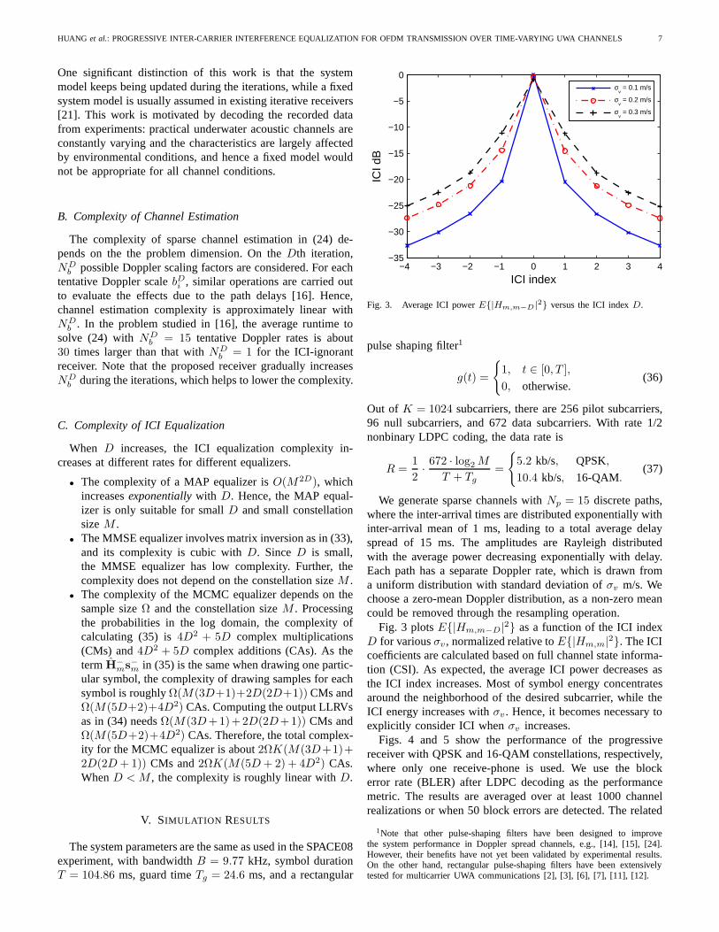
Fig. 3. Average ICI powerE|Hm,m−D |2 versus the ICI indexD.
pulse shaping filter1
g(t) =
1, t ∈ [0, T ],
0, otherwise.(36)
Out of K = 1024 subcarriers, there are 256 pilot subcarriers,96 null subcarriers, and 672 data subcarriers. With rate 1/2nonbinary LDPC coding, the data rate is
R =1
2· 672 · log2 M
T + Tg=
5.2 kb/s, QPSK,
10.4 kb/s, 16-QAM.(37)
We generate sparse channels withNp = 15 discrete paths,where the inter-arrival times are distributed exponentially withinter-arrival mean of 1 ms, leading to a total average delayspread of 15 ms. The amplitudes are Rayleigh distributedwith the average power decreasing exponentially with delay.Each path has a separate Doppler rate, which is drawn froma uniform distribution with standard deviation ofσv m/s. Wechoose a zero-mean Doppler distribution, as a non-zero meancould be removed through the resampling operation.
Fig. 3 plotsE|Hm,m−D|2 as a function of the ICI indexD for variousσv, normalized relative toE|Hm,m|2. The ICIcoefficients are calculated based on full channel state informa-tion (CSI). As expected, the average ICI power decreases asthe ICI index increases. Most of symbol energy concentratesaround the neighborhood of the desired subcarrier, while theICI energy increases withσv. Hence, it becomes necessary toexplicitly consider ICI whenσv increases.
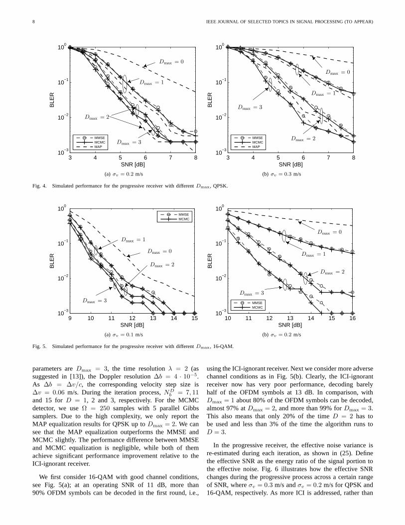
Figs. 4 and 5 show the performance of the progressivereceiver with QPSK and 16-QAM constellations, respectively,where only one receive-phone is used. We use the blockerror rate (BLER) after LDPC decoding as the performancemetric. The results are averaged over at least 1000 channelrealizations or when 50 block errors are detected. The related
1Note that other pulse-shaping filters have been designed to improvethe system performance in Doppler spread channels, e.g., [14], [15], [24].However, their benefits have not yet been validated by experimental results.On the other hand, rectangular pulse-shaping filters have been extensivelytested for multicarrier UWA communications [2], [3], [6], [7], [11], [12].
8 IEEE JOURNAL OF SELECTED TOPICS IN SIGNAL PROCESSING (TO APPEAR)
3 4 5 6 7 810
−3
10−2
10−1
100
SNR [dB]
BLE
R
MMSEMCMCMAP
Dmax = 1
Dmax = 0
Dmax = 2
Dmax = 3
(a) σv = 0.2 m/s
3 4 5 6 7 810
−3
10−2
10−1
100
SNR [dB]
BLE
R
MMSEMCMCMAP
Dmax = 3
Dmax = 1
Dmax = 0
Dmax = 2
(b) σv = 0.3 m/s
Fig. 4. Simulated performance for the progressive receiverwith different Dmax, QPSK.
9 10 11 12 13 14 1510
−3
10−2
10−1
100
SNR [dB]
BLE
R
MMSEMCMC
Dmax = 3
Dmax = 1
Dmax = 2
Dmax = 0
(a) σv = 0.1 m/s
10 11 12 13 14 15 1610
−3
10−2
10−1
100
SNR [dB]
BLE
R
MMSEMCMC
Dmax = 0
Dmax = 2
Dmax = 1
Dmax = 3
(b) σv = 0.2 m/s
Fig. 5. Simulated performance for the progressive receiverwith different Dmax, 16-QAM.
parameters areDmax = 3, the time resolutionλ = 2 (assuggested in [13]), the Doppler resolution∆b = 4 · 10−5.As ∆b = ∆v/c, the corresponding velocity step size is∆v = 0.06 m/s. During the iteration process,ND
b = 7, 11and 15 forD = 1, 2 and 3, respectively. For the MCMCdetector, we useΩ = 250 samples with 5 parallel Gibbssamplers. Due to the high complexity, we only report theMAP equalization results for QPSK up toDmax = 2. We cansee that the MAP equalization outperforms the MMSE andMCMC slightly. The performance difference between MMSEand MCMC equalization is negligible, while both of themachieve significant performance improvement relative to theICI-ignorant receiver.
We first consider 16-QAM with good channel conditions,see Fig. 5(a); at an operating SNR of 11 dB, more than90% OFDM symbols can be decoded in the first round, i.e.,
using the ICI-ignorant receiver. Next we consider more adversechannel conditions as in Fig. 5(b). Clearly, the ICI-ignorantreceiver now has very poor performance, decoding barelyhalf of the OFDM symbols at 13 dB. In comparison, withDmax = 1 about 80% of the OFDM symbols can be decoded,almost 97% atDmax = 2, and more than 99% forDmax = 3.This also means that only 20% of the timeD = 2 has tobe used and less than 3% of the time the algorithm runs toD = 3.
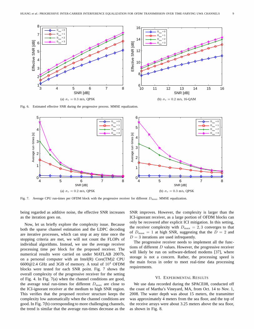
In the progressive receiver, the effective noise variance isre-estimated during each iteration, as shown in (25). Definethe effective SNR as the energy ratio of the signal portion tothe effective noise. Fig. 6 illustrates how the effective SNRchanges during the progressive process across a certain rangeof SNR, whereσv = 0.3 m/s andσv = 0.2 m/s for QPSK and16-QAM, respectively. As more ICI is addressed, rather than
HUANG et al.: PROGRESSIVE INTER-CARRIER INTERFERENCE EQUALIZATION FOR OFDM TRANSMISSION OVER TIME-VARYING UWA CHANNELS 9
3 4 5 6 7 81
2
3
4
5
6
7
8
SNR [dB]
Effe
ctiv
e S
NR
[dB
]
D
max = 0
Dmax
= 1
Dmax
= 2
Dmax
= 3
(a) σv = 0.3 m/s, QPSK
10 11 12 13 14 15 166
8
10
12
14
16
SNR [dB]
Effe
ctiv
e S
NR
[dB
]
D
max = 0
Dmax
= 1
Dmax
= 2
Dmax
= 3
(b) σv = 0.2 m/s, 16-QAM
Fig. 6. Estimated effective SNR during the progressive process. MMSE equalization.
4 5 6 7 80
1
2
3
4
5
SNR [dB]
Ave
rage
run
−tim
es [s
]
D
max = 0
Dmax
= 1
Dmax
= 2
Dmax
= 3
(a) σv = 0.2 m/s, QPSK
4 5 6 7 80
1
2
3
4
5
6
SNR [dB]
Ave
rage
run
−tim
es [s
]
D
max = 0
Dmax
= 1
Dmax
= 2
Dmax
= 3
(b) σv = 0.3 m/s, QPSK
Fig. 7. Average CPU run-times per OFDM block with the progressive receiver for differentDmax. MMSE equalization.
being regarded as additive noise, the effective SNR increasesas the iteration goes on.
Now, let us briefly explore the complexity issue. Becauseboth the sparse channel estimation and the LDPC decodingare iterative processes, which can stop at any time once thestopping criteria are met, we will not count the FLOPs ofindividual algorithms. Instead, we use the average receiverprocessing time per block for the proposed receiver. Thenumerical results were carried on under MATLAB 2007b,on a personal computer with an Intel(R) Core(TM)2 [email protected] GHz and 3GB of memory. A total of104 OFDMblocks were tested for each SNR point. Fig. 7 shows theoverall complexity of the progressive receiver for the settingof Fig. 4. In Fig. 7(a) when the channel conditions are good,the average total run-times for differentDmax are close tothe ICI-ignorant receiver at the medium to high SNR region.This verifies that the proposed receiver structure keeps thecomplexity low automatically when the channel conditions aregood. In Fig. 7(b) corresponding to more challenging channels,the trend is similar that the average run-times decrease as the
SNR improves. However, the complexity is larger than theICI-ignorant receiver, as a large portion of OFDM blocks canonly be recovered after explicit ICI mitigation. In this setting,the receiver complexity withDmax = 2, 3 converges to thatof Dmax = 1 at high SNR, suggesting that theD = 2 andD = 3 iterations are used infrequently.
The progressive receiver needs to implement all the func-tions of differentD values. However, the progressive receiverwill likely be run on software-defined modems [37], wherestorage is not a concern. Rather, the processing speed isthe main focus in order to meet real-time data processingrequirements.
VI. EXPERIMENTAL RESULTS
We use data recorded during the SPACE08, conducted offthe coast of Martha’s Vineyard, MA, from Oct. 14 to Nov. 1,2008. The water depth was about 15 meters, the transmitterwas approximately 4 meters from the sea floor, and the top ofthe receive arrays were about 3.25 meters above the sea floor,as shown in Fig. 8.

10 IEEE JOURNAL OF SELECTED TOPICS IN SIGNAL PROCESSING (TO APPEAR)
TABLE ITHE NUMBER OF UNDECODEDOFDM BLOCKS FOR DIFFERENT VALUES OFDmax IN THE PROGRESSIVE RECEIVER. JULIAN DATES 295-302. 16-QAM,
RATE 1/2 CODING, MMSE BASED ICI EQUALIZATION
System S1 (60 m); 1560 blocks S3 (200 m); 1640 blocks S5 (1000 m); 1600 blocks# of Phones Dmax=0 1 2 3 Dmax=0 1 2 3 Dmax=0 1 2 3
1 1178 1048 951 877 1229 1141 1090 1046 809 758 743 7322 731 565 431 298 775 679 630 583 395 337 296 2773 350 215 123 73 470 368 299 259 179 136 119 1044 152 77 38 19 213 126 80 57 109 86 76 665 70 32 13 5 88 47 24 15 82 65 51 376 36 19 8 4 44 17 9 8 68 46 30 237 24 12 6 2 16 9 4 0 53 34 21 188 19 10 4 1 11 3 0 0 45 22 14 129 16 7 3 0 4 2 0 0 37 19 14 1310 13 6 2 0 2 0 0 0 26 16 14 1311 11 5 2 0 0 0 0 0 25 17 11 1112 9 5 2 0 0 0 0 0 23 12 10 9
TABLE IITHE NUMBER OF UNDECODEDOFDM BLOCKS FOR DIFFERENT VALUES OFDmax IN THE PROGRESSIVE RECEIVER. JULIAN DATES 295-302. 16-QAM,
RATE 1/2 CODING, MCMC BASED ICI EQUALIZATION
System S1 (60 m); 1560 blocks S3 (200 m); 1640 blocks S5 (1000 m); 1600 blocks# of Phones Dmax=0 1 2 3 Dmax=0 1 2 3 Dmax=0 1 2 3
1 1178 1041 933 855 1229 1136 1078 1034 809 758 741 7272 731 556 397 281 775 673 619 563 395 333 291 2653 350 202 112 60 470 365 288 242 179 136 114 1034 152 75 33 16 213 120 72 48 109 85 71 605 70 31 11 4 88 42 21 12 82 64 42 306 36 19 6 3 44 16 9 5 68 43 24 237 24 11 5 2 16 9 3 1 53 30 18 178 19 9 4 0 11 3 0 0 45 20 12 109 16 7 2 0 4 1 0 0 37 17 13 1210 13 7 2 0 2 0 0 0 26 16 12 1211 11 5 2 0 0 0 0 0 25 16 11 1112 9 5 2 0 0 0 0 0 23 11 10 10
4 m
15 m
Tx60 m
S1
3.2
5 m
1.2
m
S3S5
3.2
5 m
1.2
m
3.2
5 m
1.2
m
200 m
1000 m
Fig. 8. Setup of SPACE08 experiment.
The carrier frequency wasfc = 13 kHz, and the samplingfrequency wasfs = 39.0625 kHz. More experiment descrip-tions can be found in [13], [18]. A transmission occurred everytwo hours, resulting in 12 recorded files each day. For eachtransmission, there are 20 OFDM blocks with the parametersspecified in the simulation settings. Hence, the data rate is10.4 kb/s, with 16-QAM and rate-1/2 nonbinary LDPC codingover a bandwidth of 9.77 kHz.
We report performance results for Julian dates 295 – 302(Oct. 21 – 28) and consider three receivers, labeled as S1,S3, and S5, which were 60 m, 200 m, and 1,000 m fromthe transmitter, respectively. The Doppler resolution andthedictionary size are the same as used in the simulation. The
typical channel responses for SPACE08 experiment can befound in [13, Fig. 10].
A. Performance Overview
Tables I and II report the number of OFDM blocks thathavenot been decoded correctly asD increases in the progressivereceiver, using the MMSE and MCMC equalizers, respectively,with different number of phones combined2. The data acrosseight days (Julian dates 295-302) is used. Since some recordedfiles are corrupted, there are a total of 1560, 1640 and 1600blocks processed for S1, S3 and S5, respectively. ComparingTables I and II, we see that the MCMC equalizer performsslightly better when only a small number of hydrophonesare combined, and the gap closes when more hydrophonesare available. Combining 12 hydrophones,all blocks in S1and S3 are decoded correctly using the progressive receiverwhen it reachesD = 3. There are 9 (with MMSE) or 10(with MCMC) blocks that cannot be decoded in S5. Since theperformance difference between MMSE and MCMC is small,in the following we use the MMSE results for illustration.
2For recorded data, one common practice is to investigate theperformanceas a function of the number of phones combined. Note that withmore phones,the SNR after combining increases, hence performance improvement is due toboth diversity effect and SNR increase. In this paper, the phones are selectedsequentially across the array, from top to the bottom. The frequency domainobservations are stacked into a longer vector to the equalizer. The extensionfrom single channel processing to multichannel processingis straightforward.See also [38] for the extension to MIMO equalization.

HUANG et al.: PROGRESSIVE INTER-CARRIER INTERFERENCE EQUALIZATION FOR OFDM TRANSMISSION OVER TIME-VARYING UWA CHANNELS 11
0
0.1
0.2
0.3
0.4
0.5
0.6
0.7
0.8
0.9
1
1 2 3 4 5 6 7 8
D = 3
D = 2
D = 1
D = 0
Success percentage vs. number of phones
(a) S1 (60 m)
0
0.1
0.2
0.3
0.4
0.5
0.6
0.7
0.8
0.9
1
1 2 3 4 5 6 7 8
D = 3
D = 2
D = 1
D = 0
Success percentage vs. number of phones
(b) S3 (200 m)
0
0.1
0.2
0.3
0.4
0.5
0.6
0.7
0.8
0.9
1
1 2 3 4 5 6 7 8
D = 3
D = 2
D = 1
D = 0
Success percentage vs. number of phones
(c) S5 (1000 m)
Fig. 9. The block success percentage averaged over Julian dates 295-302, SPACE08, MMSE based ICI equalization.
295 296 297 298 299 300 301 302 303
0
1
2
3
4
5
6
7
8
9
All success, D
max = 0
All success, Dmax
= 1
All success, Dmax
= 2
All success, Dmax
= 3
With errors, Dmax
= 3
(a) S1 (60 m)295 296 297 298 299 300 301 302 303
0
1
2
3
4
5
6
7
8
9
All success, D
max = 0
All success, Dmax
= 1
All success, Dmax
= 2
All success, Dmax
= 3
With errors, Dmax
= 3
(b) S3 (200 m)295 296 297 298 299 300 301 302 303
0
1
2
3
4
5
6
7
8
9
All success, D
max = 0
All success, Dmax
= 1
All success, Dmax
= 2
With errors, Dmax
= 3
(c) S5 (1000 m)
Fig. 10. Success level for each transmission of 20 OFDM blocks; four hydrophones. Markers are placed at convenient heights for illustration purposes only.
Fig. 9 shows the block success rate averaged over the eightconsecutive days using the proposed progressive receiver withthe MMSE equalizer. At short (S1) to medium (S3) ranges,we expect rich multipath and significant Doppler variationdue to the geometry. When the number of hydrophones issmall, the performance of the ICI-ignorant receiver (D = 0)is limited, and many more OFDM symbols can be decodedby applying the progressive procedure, with a largerD. Whenthe number of hydrophones is large, the ICI-ignorant receiveralready achieves excellent results for all the blocks. Checkingthe results using four hydrophones, about 90% OFDM blockscan be decoded at theD = 0 stage, and the success rateincreases to 95% whenDmax = 1, and up to 98.8% whenDmax = 3.
For S5, we see similar trends as S1 and S3, but thegap between the ICI-ignorant and progressive receivers getssmaller. When four hydrophones are combined, over 93%blocks can be decoded by ignoring the ICI, and the successrate increases to 96% when the progressive receiver reachesD = 3.
B. Environmental Impact
Using four hydrophones for combining, Table I shows thatthere are 19 out of 1560 blocks with decoding errors in S1,
57 out of 1640 blocks with decoding errors in S3, and 66 outof 1600 blocks with decoding errors in S5, for the progressivereceiver withDmax = 3. Fig. 10 illustrates the success levelof each transmission of 20 OFDM blocks across the 8-dayperiod. Each day, we have about 12 files recorded (a few filesare corrupted). “All success” means that all 20 blocks in thatfile, of duration20(T + Tg) = 2.59 s, can be decoded, while“With errors” means that some blocks cannot be decoded outof 20 blocks in the file.
The significant wave height and average wind speed areshown in Fig. 11. The significant wave height is calculated asH = 4
√m0, wherem0 is the zeroth-moment of the variance
spectrum obtained by integration of the variance spectrum.Wecan observe some correlations between Fig. 10 and Fig. 11.There are two periods that the progressive receiver withD > 0is used: Julian dates 296-297 and Julian dates 300-301, duringwhich the wind speed and the wave height are high. Forthe rest of the days, the ICI-ignorant receiver can decodeall the blocks. Fig. 10 confirms that the progressive receivercan self adapt to channel conditions, maintaining both goodperformance and low complexity.
C. Progressive versus Iterative ICI-aware receivers
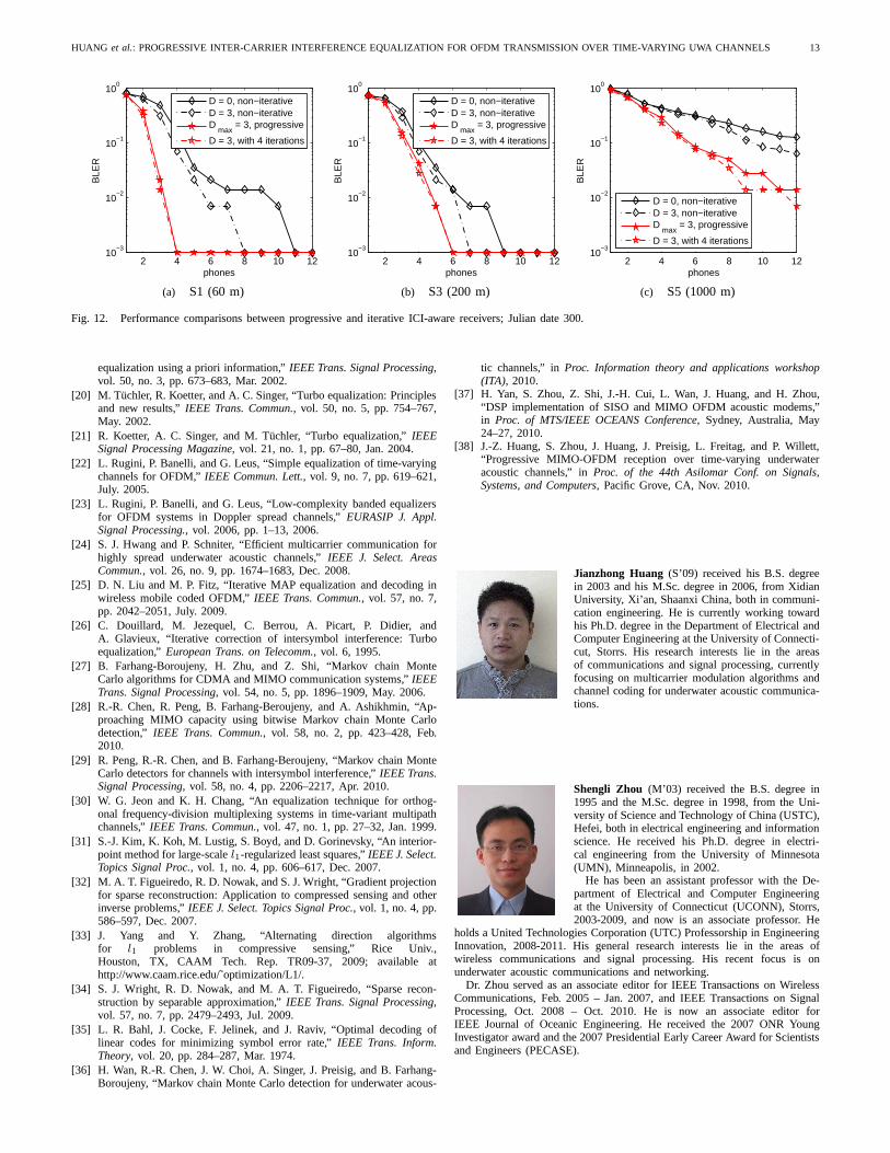
In Fig. 12, we compare the performance between theproposed progressive receiver and an iterative ICI-aware re-

12 IEEE JOURNAL OF SELECTED TOPICS IN SIGNAL PROCESSING (TO APPEAR)
295 296 297 298 299 300 301 302 3030
1
2
3
4
Julian Date in 2008
Wav
e he
ight
(m
)
295 296 297 298 299 300 301 302 3030
5
10
15
20
Julian Date in 2008W
ind
spee
d (m
/s)
Fig. 11. Significant wave height and average wind speed for selected days in SPACE08.
ceiver that fixes the channel model atD = 3, but iteratesseveral times; we focus on channels with large Doppler spread(Julian Date 300). Obviously, the latter receiver has muchhigher complexity, and is not well-motivated in good channelconditions. After the first iteration, we see that the ICI-awarereceiver outperforms the ICI-ignorant receiver. As the iterationcontinues, the progressive receiver catches up with the iterativeICI-aware receiver, and the performance difference is negligi-ble. Hence, the progressive receiver collects the performancebenefits as the iterative ICI-aware receiver, but enjoys muchlower complexity in various channel conditions.
VII. C ONCLUSIONS
In this paper we developed a progressive receiver for OFDMtransmission over time-varying underwater acoustic channels.During the iterations, it updates thesystem model to accountfor channels with large Doppler spreads, while fully utilizingsoft information from the previous iteration for enhancedsparse channel estimation and inter-carrier interferenceequal-ization. Extensive tests based on experimental data showedthat the proposed receiver enjoys low complexity in goodchannel conditions while maintaining excellent performanceeven when the channel deteriorates. Adapting to channelvariations without anya priori information, the proposedreceiver is very promising for practical underwater systems.
ACKNOWLEDGEMENT
We thank Dr. James Preisig and his team for conducting theSPACE08 experiment.
REFERENCES
[1] J.-Z. Huang, S. Zhou, J. Huang, C. R. Berger, and P. Willett, “Progressiveinter-carrier interference equalization for OFDM transmission over time-varying underwater acoustic channels,” inProc. of MTS/IEEE OCEANSConf., Sydney, Australia, May 2010.
[2] B. Li, S. Zhou, M. Stojanovic, L. Freitag, and P. Willett,“Multicarriercommunication over underwater acoustic channels with nonuniformDoppler shifts,”IEEE J. Ocean. Eng., vol. 33, no. 2, pp. 198–209, Apr.2008.
[3] M. Stojanovic, “Low complexity OFDM detector for underwater chan-nels,” in Proc. of MTS/IEEE OCEANS Conf., Boston, MA, Sept. 18-21,2006.
[4] ——, “OFDM for underwater acoustic communications: Adaptive syn-chronization and sparse channel estimation,” inProc. of Intl. Conf. onAcoustics, Speech and Signal Proc., Las Vegas, NV, Mar. 30 – Apr. 4,2008.
[5] J. Huang, S. Zhou, and P. Willett, “Nonbinary LDPC codingformulticarrier underwater acoustic communication,”IEEE J. Select. AreasCommun., vol. 26, no. 9, pp. 1684–1696, Dec. 2008.
[6] T. Kang and R. A. Iltis, “Iterative carrier frequency offset and channelestimation for underwater acoustic OFDM systems,”IEEE J. Select.Areas Commun., vol. 26, no. 9, pp. 1650–1661, Dec. 2008.
[7] Y. Emre, V. Kandasamy, T. M. Duman, P. Hursky, and S. Roy, “Multi-input multi-output OFDM for shallow-water UWA communications,” inAcoustics’08 Conference, Paris, France, July 2008.
[8] B. Li, J. Huang, S. Zhou, K. Ball, M. Stojanovic, L. Freitag, and P. Wil-lett, “MIMO-OFDM for high rate underwater acoustic communications,”IEEE J. Ocean. Eng., vol. 34, no. 4, pp. 634–644, Oct. 2009.
[9] J. Huang, J.-Z. Huang, C. R. Berger, S. Zhou, and P. Willett, “Iterativesparse channel estimation and decoding for underwater MIMO-OFDM,”EURASIP Journal on Advances in Signal Processing., vol. 2010, articleID 460379.
[10] C. R. Berger, W. Chen, S. Zhou, and J. Huang, “A Simple andEffective Noise Whitening Method for Underwater Acoustic OrthogonalFrequency Division Multiplexing,”Journal of Acoustical Society ofAmerica, vol. 127, no. 4, pp. 2358-2367, April 2010.
[11] G. Leus and P. A. van Walree, “Multiband OFDM for covert acousticcommunications,”IEEE J. Select. Areas Commun., vol. 26, no. 9, pp.1662–1673, Dec. 2008.
[12] K. Tu, D. Fertonani, T. M. Duman, and P. Hursky, “Mitigation ofintercarrier interference in OFDM systems over underwateracousticchannels,” inProc. of MTS/IEEE OCEANS Conf., Bremen, Germany,May. 2009.
[13] C. R. Berger, S. Zhou, J. Preisig, and P. Willett, “Sparse channelestimation for multicarrier underwater acoustic communication: Fromsubspace methods to compressed sensing,”IEEE Trans. Signal Process-ing, vol. 58, no. 3, pp. 1708 – 1721, Mar. 2010.
[14] W. Kozek, and A. F. Molisch, “Nonorthogonal pulse shapes for mul-ticarrier communications in doubly dispersive channels,”IEEE Journalon selected areas in communications., vol. 16, no. 8, pp. 1579-1589,Oct. 1998.
[15] T. Strihmer, and S. Beaver, “Optimal OFDM design for time-frequencydispersive channels,”IEEE Transactions on communications., vol. 51,no. 7, pp. 1-12, July. 2003.
[16] J.-Z. Huang, C. R. Berger, S. Zhou, and J. Huang, “Comparison of basispursuit algorithms for sparse channel estimation in underwater acousticOFDM,” in Proc. of MTS/IEEE OCEANS Conf., Sydney, Australia, May.2010.
[17] A. Song, M. Badiey, H.-C. Song, W. S. Hodgkiss, M. B. Porter, and theKauaiEx Group, “Impact of ocean variability on coherent underwateracoustic communications during the Kauai experiment (KauaiEx),” J.Acoustical Society of America., vol. 123, no. 2, pp. 856–865, Feb. 2008.
[18] L. Freitag and S. Singh, “Performance of micro-modem PSK signallingunder variable conditions during the 2008 RACE and SPACE experi-ments,” inProc. of MTS/IEEE OCEANS Conf., Biloxi, MS, Oct. 2009.
[19] M. Tuchler, A. C. Singer, and R. Koetter, “Minimum meansquared error
HUANG et al.: PROGRESSIVE INTER-CARRIER INTERFERENCE EQUALIZATION FOR OFDM TRANSMISSION OVER TIME-VARYING UWA CHANNELS 13
2 4 6 8 10 1210
−3
10−2
10−1
100
phones
BLE
R
D = 0, non−iterativeD = 3, non−iterativeD
max = 3, progressive
D = 3, with 4 iterations
(a) S1 (60 m)
2 4 6 8 10 1210
−3
10−2
10−1
100
phones
BLE
R
D = 0, non−iterativeD = 3, non−iterativeD
max = 3, progressive
D = 3, with 4 iterations
(b) S3 (200 m)
2 4 6 8 10 1210
−3
10−2
10−1
100
phones
BLE
R
D = 0, non−iterativeD = 3, non−iterativeD
max = 3, progressive
D = 3, with 4 iterations
(c) S5 (1000 m)
Fig. 12. Performance comparisons between progressive and iterative ICI-aware receivers; Julian date 300.
equalization using a priori information,”IEEE Trans. Signal Processing,vol. 50, no. 3, pp. 673–683, Mar. 2002.
[20] M. Tuchler, R. Koetter, and A. C. Singer, “Turbo equalization: Principlesand new results,”IEEE Trans. Commun., vol. 50, no. 5, pp. 754–767,May. 2002.
[21] R. Koetter, A. C. Singer, and M. Tuchler, “Turbo equalization,” IEEESignal Processing Magazine, vol. 21, no. 1, pp. 67–80, Jan. 2004.
[22] L. Rugini, P. Banelli, and G. Leus, “Simple equalization of time-varyingchannels for OFDM,”IEEE Commun. Lett., vol. 9, no. 7, pp. 619–621,July. 2005.
[23] L. Rugini, P. Banelli, and G. Leus, “Low-complexity banded equalizersfor OFDM systems in Doppler spread channels,”EURASIP J. Appl.Signal Processing., vol. 2006, pp. 1–13, 2006.
[24] S. J. Hwang and P. Schniter, “Efficient multicarrier communication forhighly spread underwater acoustic channels,”IEEE J. Select. AreasCommun., vol. 26, no. 9, pp. 1674–1683, Dec. 2008.
[25] D. N. Liu and M. P. Fitz, “Iterative MAP equalization anddecoding inwireless mobile coded OFDM,”IEEE Trans. Commun., vol. 57, no. 7,pp. 2042–2051, July. 2009.
[26] C. Douillard, M. Jezequel, C. Berrou, A. Picart, P. Didier, andA. Glavieux, “Iterative correction of intersymbol interference: Turboequalization,”European Trans. on Telecomm., vol. 6, 1995.
[27] B. Farhang-Boroujeny, H. Zhu, and Z. Shi, “Markov chainMonteCarlo algorithms for CDMA and MIMO communication systems,”IEEETrans. Signal Processing, vol. 54, no. 5, pp. 1896–1909, May. 2006.
[28] R.-R. Chen, R. Peng, B. Farhang-Beroujeny, and A. Ashikhmin, “Ap-proaching MIMO capacity using bitwise Markov chain Monte Carlodetection,” IEEE Trans. Commun., vol. 58, no. 2, pp. 423–428, Feb.2010.
[29] R. Peng, R.-R. Chen, and B. Farhang-Beroujeny, “Markovchain MonteCarlo detectors for channels with intersymbol interference,” IEEE Trans.Signal Processing, vol. 58, no. 4, pp. 2206–2217, Apr. 2010.
[30] W. G. Jeon and K. H. Chang, “An equalization technique for orthog-onal frequency-division multiplexing systems in time-variant multipathchannels,”IEEE Trans. Commun., vol. 47, no. 1, pp. 27–32, Jan. 1999.
[31] S.-J. Kim, K. Koh, M. Lustig, S. Boyd, and D. Gorinevsky,“An interior-point method for large-scalel1-regularized least squares,”IEEE J. Select.Topics Signal Proc., vol. 1, no. 4, pp. 606–617, Dec. 2007.
[32] M. A. T. Figueiredo, R. D. Nowak, and S. J. Wright, “Gradient projectionfor sparse reconstruction: Application to compressed sensing and otherinverse problems,”IEEE J. Select. Topics Signal Proc., vol. 1, no. 4, pp.586–597, Dec. 2007.
[33] J. Yang and Y. Zhang, “Alternating direction algorithmsfor l1 problems in compressive sensing,” Rice Univ.,Houston, TX, CAAM Tech. Rep. TR09-37, 2009; available athttp://www.caam.rice.edu/˜optimization/L1/.
[34] S. J. Wright, R. D. Nowak, and M. A. T. Figueiredo, “Sparse recon-struction by separable approximation,”IEEE Trans. Signal Processing,vol. 57, no. 7, pp. 2479–2493, Jul. 2009.
[35] L. R. Bahl, J. Cocke, F. Jelinek, and J. Raviv, “Optimal decoding oflinear codes for minimizing symbol error rate,”IEEE Trans. Inform.Theory, vol. 20, pp. 284–287, Mar. 1974.
[36] H. Wan, R.-R. Chen, J. W. Choi, A. Singer, J. Preisig, andB. Farhang-Boroujeny, “Markov chain Monte Carlo detection for underwater acous-
tic channels,” inProc. Information theory and applications workshop(ITA), 2010.
[37] H. Yan, S. Zhou, Z. Shi, J.-H. Cui, L. Wan, J. Huang, and H.Zhou,“DSP implementation of SISO and MIMO OFDM acoustic modems,”in Proc. of MTS/IEEE OCEANS Conference, Sydney, Australia, May24–27, 2010.
[38] J.-Z. Huang, S. Zhou, J. Huang, J. Preisig, L. Freitag, and P. Willett,“Progressive MIMO-OFDM reception over time-varying underwateracoustic channels,” inProc. of the 44th Asilomar Conf. on Signals,Systems, and Computers, Pacific Grove, CA, Nov. 2010.
Jianzhong Huang (S’09) received his B.S. degreein 2003 and his M.Sc. degree in 2006, from XidianUniversity, Xi’an, Shaanxi China, both in communi-cation engineering. He is currently working towardhis Ph.D. degree in the Department of Electrical andComputer Engineering at the University of Connecti-cut, Storrs. His research interests lie in the areasof communications and signal processing, currentlyfocusing on multicarrier modulation algorithms andchannel coding for underwater acoustic communica-tions.
Shengli Zhou (M’03) received the B.S. degree in1995 and the M.Sc. degree in 1998, from the Uni-versity of Science and Technology of China (USTC),Hefei, both in electrical engineering and informationscience. He received his Ph.D. degree in electri-cal engineering from the University of Minnesota(UMN), Minneapolis, in 2002.
He has been an assistant professor with the De-partment of Electrical and Computer Engineeringat the University of Connecticut (UCONN), Storrs,2003-2009, and now is an associate professor. He
holds a United Technologies Corporation (UTC) Professorship in EngineeringInnovation, 2008-2011. His general research interests liein the areas ofwireless communications and signal processing. His recentfocus is onunderwater acoustic communications and networking.
Dr. Zhou served as an associate editor for IEEE Transactionson WirelessCommunications, Feb. 2005 – Jan. 2007, and IEEE Transactions on SignalProcessing, Oct. 2008 – Oct. 2010. He is now an associate editor forIEEE Journal of Oceanic Engineering. He received the 2007 ONR YoungInvestigator award and the 2007 Presidential Early Career Award for Scientistsand Engineers (PECASE).
14 IEEE JOURNAL OF SELECTED TOPICS IN SIGNAL PROCESSING (TO APPEAR)
Jie Huang received the B.S. degree in 2001 andthe Ph. D. degree in 2006, from the University ofScience and Technology of China (USTC), Hefei,both in electrical engineering and information sci-ence. He was a post-doctoral researcher with theDepartment of Electrical and Computer Engineeringat the University of Connecticut (UCONN), Storrs,from July 2007 to June 2009, and is now a researchassistant professor at the University of Connecticut(UCONN), Storrs.
His general research interests lie in the areas ofcommunications and signal processing, specially error control coding theoryand coded modulation. His recent focus is on signal processing, channelcoding and network coding for underwater acoustic communications andnetworks.
Christian R. Berger (M’09) was born in Heidel-berg, Germany, on September 12, 1979. He receivedthe Dipl.-Ing. degree from the Universitat Karlsruhe(TH), Karlsruhe, Germany in 2005, and the Ph.D.degree from the University of Connecticut, Storrs,in 2009, both in electrical engineering.
In the summer of 2006, he was as a visitingscientist at the Sensor Networks and Data FusionDepartment of the FGAN Research Institute, Wacht-berg, Germany. He is currently a post-doctoral re-searcher at the Department of Electrical and Com-
puter Engineering, Carnegie Mellon University, Pittsburgh, USA. His researchinterests lie in the areas of communications and signal processing, includingdistributed estimation in wireless sensor networks, wireless positioning andsynchronization, underwater acoustic communications andnetworking.
Dr. Berger has served as a reviewer for the IEEE Transactionson SignalProcessing, Wireless Communications, Vehicular Technology, and Aerospaceand Electronic Systems. In 2008 he was member of the technical programcommittee and session chair for the 11th International Conference on Infor-mation Fusion in Cologne, Germany.
Peter Willett (F’03) received his BASc (Engineer-ing Science) from the University of Toronto in 1982,and his PhD degree from Princeton University in1986.
He has been a faculty member at the Universityof Connecticut ever since, and since 1998 has beena Professor. His primary areas of research havebeen statistical signal processing, detection, machinelearning, data fusion and tracking. He has interests inand has published in the areas of change/abnormalitydetection, optical pattern recognition, communica-
tions and industrial/security condition monitoring.Dr. Willett is editor-in-chief for IEEE Transactions on Aerospace and
Electronic Systems, and until recently was associate editor for three activejournals: IEEE Transactions on Aerospace and Electronic Systems (for DataFusion and Target Tracking) and IEEE Transactions on Systems, Man, andCybernetics, parts A and B. He is also associate editor for the IEEE AESMagazine, editor of the AES Magazines periodic Tutorial issues, associateeditor for ISIFs electronic Journal of Advances in Information Fusion, and isa member of the editorial board of IEEEs Signal Processing Magazine. He hasbeen a member of the IEEE AESS Board of Governors since 2003. He wasGeneral Co- Chair (with Stefano Coraluppi) for the 2006 ISIF/IEEE FusionConference in Florence, Italy, Program Co-Chair (with Eugene Santos) forthe 2003 IEEE Conference on Systems, Man, and Cybernetics inWashingtonDC, and Program Co-Chair (with Pramod Varshney) for the 1999FusionConference in Sunnyvale.