IEEE – cable workshop – Bern 14/04/2010 : short-circuit ... · short-circuit protection for...
56
IEEE – cable workshop – Bern 14/04/2010 : short-circuit protection for combined overhead line - cable circuits Luc Uyttersprot
Transcript of IEEE – cable workshop – Bern 14/04/2010 : short-circuit ... · short-circuit protection for...

IEEE – cable workshop – Bern 14/04/2010 : short-circuit protection for combined overhead line - cable circuits
Luc Uyttersprot

5/05/201022
Why, when shall we use mixed conductor technologies ?
• Crossing of an area which is too wide for an overhead line spanExamples : river, lake, fjord, etc...
• Crossing of an urbanised areaThis can be the case for an existing substation originally located outside the city but today included in the conurbation
• Difficulties to insure clearances associated with an overhead lineHere are some examples : • Connection of several circuits to a Gas Insulated Substation;• Connection of a generation plant to the grid
• Speeding up the process to gain permissionIt is normally easier to get the permission for an underground cable circuit than for an overhead line. This can be critical for an industrial plant or for a generation plant seeking a connection with the grid
5/05/20103
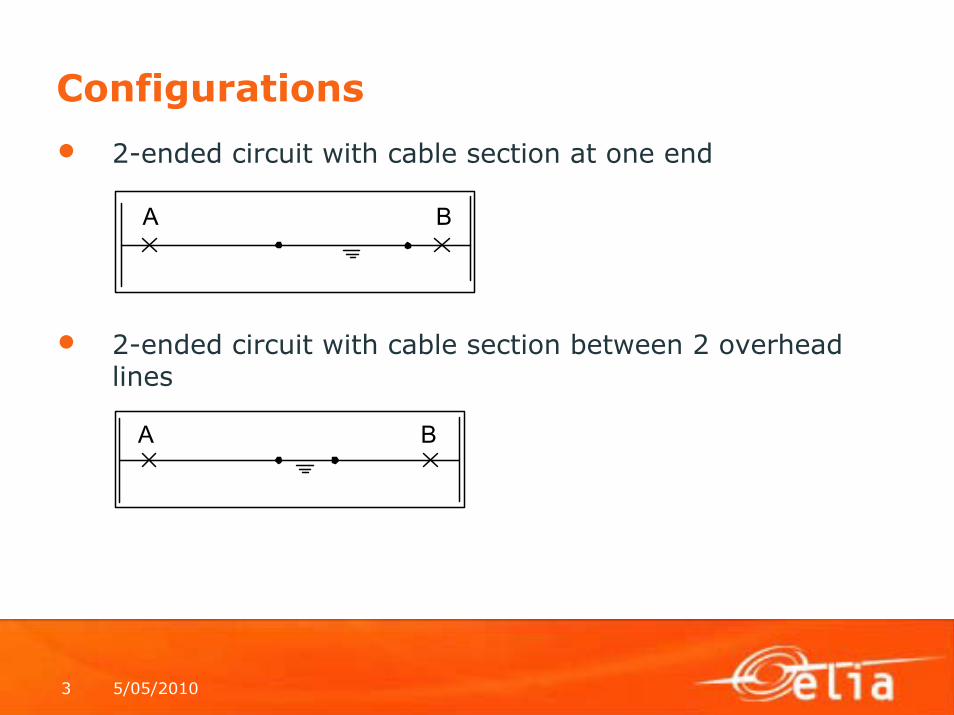
Configurations
• 2-ended circuit with cable section at one end
• 2-ended circuit with cable section between 2 overhead lines
A B
A B

5/05/20104
Configurations (continued)• 2-ended circuit with multiple cable sections
• 3-ended circuit with a transformer tap at one end connected with an underground cable
A B
A B
C

5/05/20105
Configurations (continued)• 3-ended circuit with all branches connected to a busbar
and with one branche in underground cable
A B
C

5/05/20106
Calculation of serie sequence impedances of OHL
1. Modified Carson’s equations :
• Self impedance of a conductor with an earth return :
With : R = conductor AC resistance;GMRc = geometric mean radius of a single conductorf = frequencyDe = equivalent spacing of the earth return path = With p= earth resistivity (Ωcm²/cm)
• Mutual inductance between 2 conductors :
With : D=spacing between the parallel conductors
/km GMRc
Delogf0029,0jf000988,0RZii 10 Ω++=
fp216
/km DDelogf0029,0jf000988,0Zij 10 Ω+=
i j
D

5/05/20107
Calculation of serie sequence impedances of OHL (continued)2. Primitive impedance matrix for a single circuit OHL with an earth conductor :
With Zii= self impedance of conductor iZij= mutual impedance between
conductors i and j
⎟⎟⎟⎟⎟
⎠
⎞
⎜⎜⎜⎜⎜
⎝
⎛
⎟⎟⎠
⎞⎜⎜⎝
⎛=
⎟⎟⎟⎟⎟
⎠
⎞
⎜⎜⎜⎜⎜
⎝
⎛
⎟⎟⎟⎟⎟
⎠
⎞
⎜⎜⎜⎜⎜
⎝
⎛
=
⎟⎟⎟⎟⎟
⎠
⎞
⎜⎜⎜⎜⎜
⎝
⎛
ΔΔΔ
=Δ
InIcIbIa
*ZnnZcnZcnZcc
InIcIbIa
*
ZnnZncZnbZnaZcnZccZcbZcaZbnZbcZbbZbaZanZacZabZaa
0VcVbVa
I*ZV

5/05/20108
Calculation of serie sequence impedances of OHL - continued
3.Reduction of the matrix
We can eliminate the last row and the last colum :
with
4. Sequence impedance matrix
with
⎟⎟⎟
⎠
⎞
⎜⎜⎜
⎝
⎛=
⎟⎟⎟
⎠
⎞
⎜⎜⎜
⎝
⎛
ΔΔΔ
IcIbIa
*ZredVcVbVa
T1 Zcn*Znn*ZcnZccZred −−=
A*Zred*AZseq 1−=⎟⎟⎟
⎠
⎞
⎜⎜⎜
⎝
⎛=
2
2
aa1aa1111
A

5/05/20109
Sequence impedances of OHL - continued
4.Examples :
ItemSection (mm²)
Type Circuit Z1 Z0 Z1 Z0
150 kV OHL 504 & 445 AMS-Z & AMS double 0,082 + j 0,403 0,254 + j 0,067 + j 0,419 0,176 + j 0,929150 kV OHL 445 AMS double 0,078 + j 0,409 0,304 + j 1,261 0,099 + j 0,470 0,401 + j 1,396230 kV OHL single 0,060 + j 0,472 0,230 + j 1,590380 kV OHL 2 * 705 AMS-2Z double 0,031 + j 0,304 0,226 + j 0,867
Characteristics Calculations (Ω/km) Measurements (Ω/km)

5/05/201010
Calculation of sequence impedances of underground cable1. Grounding methods for the sheaths
• Single point bonding+ : no heating effect due to
circulating currents in the sheath- : overvoltages at the free end
dangerous ground potential differencebetween both ends is limited bythe presence of a ground conductor
• Solid bonding + : no overvoltage on the sheath- : circulating currents in the sheath
• Cross bonding+ : no overvoltage on the sheath;
limited circulating currents in the sheath
The grounding method will have an impact on the zero-sequenceimpedance
earth continuity conductor
Surge arrestors

5/05/201011
Calculation of serie sequence impedances of underground cable - continued2. Configuration
• 3 solid dielectric single phase underground cables• Solid grounding
3. Primitive impedance matrixWe have to take into account following impedances : • Self impedance of each conductor• Mutual impedance between 2 conductors• Self impedance of the sheath• Mutual mpedance between conductor and shield

5/05/201012
Calculation of serie sequence impedances of underground cable - continued
⎟⎟⎟⎟⎟⎟⎟⎟
⎠
⎞
⎜⎜⎜⎜⎜⎜⎜⎜
⎝
⎛
⎟⎟⎠
⎞⎜⎜⎝
⎛=
⎟⎟⎟⎟⎟⎟⎟⎟
⎠
⎞
⎜⎜⎜⎜⎜⎜⎜⎜
⎝
⎛
⎟⎟⎟⎟⎟⎟⎟⎟
⎠
⎞
⎜⎜⎜⎜⎜⎜⎜⎜
⎝
⎛
=
⎟⎟⎟⎟⎟⎟⎟⎟
⎠
⎞
⎜⎜⎜⎜⎜⎜⎜⎜
⎝
⎛
ΔΔΔ
3Is2Is1Is
IcIbIa
*ZssZcsZcsZcc
3Is2Is1Is
IcIbIa
*
3s3Zs2s3Zs1s3Zsc3Zsb3Zsa3Zs3s2Zs2s2Zs1s2Zsc2Zsb2Zsa2Zs3s1Zs2s1Zs1s1Zsc1Zsb1Zsa1Zs3Zcs2Zcs1ZcsZccZcbZca3Zbs2Zbs1ZbsZbcZbbZba3Zas2Zas1ZasZacZabZaa
000VcVbVa
Primitive impedance matrix :
Va
Vb
Va’
Vb’
Vc’Vc
Zaa
Zbb
Zcc
s1
s2
s3
Zs1s1
Zs2s2
Zs3s3
Zab
Zbc
Zac
Zas1

5/05/201013
4. Matrix reduction
We can eliminate the 3 last rows and the 3 last colums :
with
⎟⎟⎟⎟⎟⎟⎟⎟
⎠
⎞
⎜⎜⎜⎜⎜⎜⎜⎜
⎝
⎛
⎟⎟⎠
⎞⎜⎜⎝
⎛=
⎟⎟⎟⎟⎟⎟⎟⎟
⎠
⎞
⎜⎜⎜⎜⎜⎜⎜⎜
⎝
⎛
ΔΔΔ
3Is2Is1Is
IcIbIa
*ZssZcsZcsZcc
000VcVbVa
⎟⎟⎟
⎠
⎞
⎜⎜⎜
⎝
⎛=
⎟⎟⎟
⎠
⎞
⎜⎜⎜
⎝
⎛
ΔΔΔ
IcIbIa
*ZredVcVbVa
T1 Zcs*Zss*ZcsZccZred −−=
Calculation of serie sequence impedances of underground cable - continued

5/05/201014
Calculation of serie sequence impedances of underground cable - continued5. Sequence impedances matrix
with
6. Example• 230 kV single conductor cable• 1200 mm² Cu• Earth resistivity : 100 Ωm• f=60 Hz• Trefoil configuration• Solid bonding• No earth conductor• External radius : 0,0538 m
A*Zred*AZseq 1−=⎟⎟⎟
⎠
⎞
⎜⎜⎜
⎝
⎛=
2
2
aa1aa1111
A

5/05/201015
Example - continued
Z
.079 .8169i+
.0592 .6766i+
.0592 .6766i+
.0592 .7383i+
.0592 .6766i+
.0592 .6766i+
.0592 .6766i+
.079 .8169i+
.0592 .6766i+
.0592 .6766i+
.0592 .7383i+
.0592 .6766i+
.0592 .6766i+
.0592 .6766i+
.079 .8169i+
.0592 .6766i+
.0592 .6766i+
.0592 .7383i+
.0592 .7383i+
.0592 .6766i+
.0592 .6766i+
.2151 .7383i+
.0592 .6766i+
.0592 .6766i+
.0592 .6766i+
.0592 .7383i+
.0592 .6766i+
.0592 .6766i+
.2151 .7383i+
.0592 .6766i+
.0592 .6766i+
.0592 .6766i+
.0592 .7383i+
.0592 .6766i+
.0592 .6766i+
.2151 .7383i+
⎛⎜⎜⎜⎜⎜⎜⎝
⎞⎟⎟⎟⎟⎟⎟⎠
:=
Zcc
.079 .8169i+
.0592 .6766i+
.0592 .6766i+
.0592 .6766i+
.079 .8169i+
.0592 .6766i+
.0592 .6766i+
.0592 .6766i+
.079 .8169i+
⎛⎜⎜⎝
⎞⎟⎟⎠
:= Zcs
.0592 .7383i+
.0592 .6766i+
.0592 .6766i+
.0592 .6766i+
.0592 .7383i+
.0592 .6766i+
.0592 .6766i+
.0592 .6766i+
.0592 .7383i+
⎛⎜⎜⎝
⎞⎟⎟⎠
:=
Zss
.2151 .7383i+
.0592 .6766i+
.0592 .6766i+
.0592 .6766i+
.2151 .7383i+
.0592 .6766i+
.0592 .6766i+
.0592 .6766i+
.2151 .7383i+
⎛⎜⎜⎝
⎞⎟⎟⎠
:= A
1
1
1
1
.5− .866i−
.5− .866i+
1
.5− .866i+
.5− .866i−
⎛⎜⎜⎝
⎞⎟⎟⎠
:=
Zred Zcc Zcs Zss 1−⋅ ZcsT⋅−:= Zseq A 1− Zred⋅ A⋅:=
Zseq
0.174 0.09i+
0
0
0
0.041 0.132i+
0
0
0
0.041 0.132i+
⎛⎜⎜⎝
⎞⎟⎟⎠
=

5/05/201016
Calculation of serie sequence impedances of underground cable - continued7. Other examples
Comparison of serie sequence impedances of OHL and underground cable
ItemSection (mm²)
Type Bonding Z1 Z0 Z1 Z0
150 kV 800 Alu (XLPE) cross bonding,earth conductor
0,047 + j 0,115 0,084 + j 0,070 0,041 + j 0,124 0,134 + j 0,109
150 kV 2000 Alu (XLPE) cross bonding,earth conductor
0,023 + j 0,109 0,156 + j 0,124
230 kV 1200 Cu (XLPE) solid bonding,no earth conductor
0,041 + j 0,132 0,174 + j 0,09
Characteristics Calculations (Ω/km) Measurements (Ω/km)
Item Z1 (Ω/km) Z0 (Ω/km)150 kV OHL 0,067 + j 0,419 = 0,424 ∟81° 0,176 + j 0,929 = 0,946 ∟79°150 kV cable 0,041 + j 0,124 = 0,131 ∟72° 0,134 + j 0,109 = 0,173 ∟39°230 kV OHL 0,060 + j 0,472 = 0,476 ∟83° 0,230 + j 1,590 = 1,607 ∟82°230 kV cable 0,041 + j 0,132 = 0,138 ∟73° 0,174 + j 0,09 = 0,196 ∟27°

5/05/201017
8. Direct calculation of Z0 for simple configurations :
equivalent to
With : Z0c = Z0 conductorZ0s = Z0 sheath These values are calculatedZ0m = Z0 mutual based on Carson’s equation
Calculation of serie sequence impedances of underground cable - continued
Va0
Vb0
Vc0
s1
s2
s3
Ia0
Ib0
Ic0
Is
Is
Is
Ig

5/05/201018
• Current return in the sheath only :
• Current return in the ground only :
• Current return in the sheath and in the ground :
Direct calculation of Z0 for simple configurations- continued
c0Zm0Zm0Zc0Z0Z =+−=
m0Z*2s0Zc0Z0Z −+=
( )s0Zm0Zc0Z
s0Zm0Z*m0Zs0Zm0Zc0Z0Z
2
−=−
+−=

5/05/201019
Protection of cable and mixed conductor circuits
• High speed tripping is required because excessive heatingcan damage the cable
• Most faults on cable are single phase faults
Protections with high ground – fault sensitivityare required

5/05/201020
Distance protection applied to cable and mixed conductor circuits – distance calculation
• 3-ph fault• Measures : Vph-n and Iph
• Calculation :
• 2-ph fault• Calculation :
ZlineIph
nVph=
−
ZlineIbIa
Ib*ZlineIa*ZlineIbIaVbVa
=−−
=−−

5/05/201021
Distance calculation
• 1-ph fault
Zsource Zline
Relay location
Z1source Z1line
Z2source Z2line
Zosource Zoline
V1
V2
V0
I1
I2
I0
[ ]
L1Z*3L1ZL0Z0kwith
In*0kIaVaL1Z
In*0kIa*L1ZL1Z*3
L1ZL0Z*InIa*L1Z
0I*L1Z0I*L0ZIa*L1Z0I*L0Z2I*L2Z1I*L1ZVVV 021
−=
+=
+=
=⎥⎦
⎤⎢⎣
⎡⎟⎠⎞
⎜⎝⎛ −
+=
=−+==++=++

5/05/201022
k0 factor
1Z*31Z0Z0k −
=
Item Z1 (Ω/km) Z0 (Ω/km) k0150 kV OHL 0,067 + j 0,419 0,176 + j 0,929 0,409 ∟-3°150 kV cable 0,041 + j 0,124 0,134 + j 0,109 0,240 ∟-81°230 kV OHL 0,060 + j 0,472 0,230 + j 1,590 0,792 ∟-1,4°230 kV cable 0,039 + j 0,127 0,172 + j 0,084 0,351 ∟-91°
Conclusion :
• k0 factor OHL ≠k0 factor for cable (angle, amplitude)
• use of a distance protection which accepts complex k0 is mandatory
• for mixed conductor circuits, the use of a distance protection withmore than one k0 is mandatory

5/05/201023
Application of k0 for an underground cable –single point bonding
Distance relay at A• In case of an internal fault (single phase), the fault current returns in the
sheath only :
• Z0 is proportional to the distance to the fault which implies that k0 is a constant
• For an external fault, there is no current in the sheath
• There is a discontinuity in the compensated loop impedance betweeninternal and external fault at B :
Z0int < Z0ext Zcomp int < Zcomp extZ1 can cover the whole cable between A and B
A B
m0Z*2s0Zc0Z0Z −+=
c0Zm0Zm0Zc0Z0Z =+−=
( )0k1*3L0ZL1Z*2
In*0kIaVaZcomp
++
=+
=

5/05/201024
Application of k0 for an underground cable –single point bonding
Distance relay at B :• For an internal fault at B, the impedance measured by the relay is not
zero because the fault current is returning to the source via the sheathand end A.
• Internal fault at A : there is no current in the sheath :
• External fault at A : there is also no current in the sheath;
there is a continuity in the compensated loop impedance at end A between internal and external fault; it is thus not possible to cover withZ1 the whole cable
c0Zm0Zm0Zc0Z0Z =+−=

5/05/201025
Application of k0 for an underground cable –solid bonding
• In case of an internal fault, the fault current returns in the sheath and in the ground in parallel :
• Z0 is not proportional to the distance to the fault which implies that k0 is not a constant
• For an external fault, there is also current in the sheats (because the sheaths are grounded at both ends)
• There is continuity in the compensated loop impedance between internaland external fault; it is thus not possible to cover with Z1 the wholecable nor at end A, nor at end B
( )s0Zm0Zc0Z
s0Zm0Z*m0Zs0Zm0Zc0Z0Z
2
−=−
+−=
BA
s0Zm0Zc0Z0Z
2
−=
5/05/201026
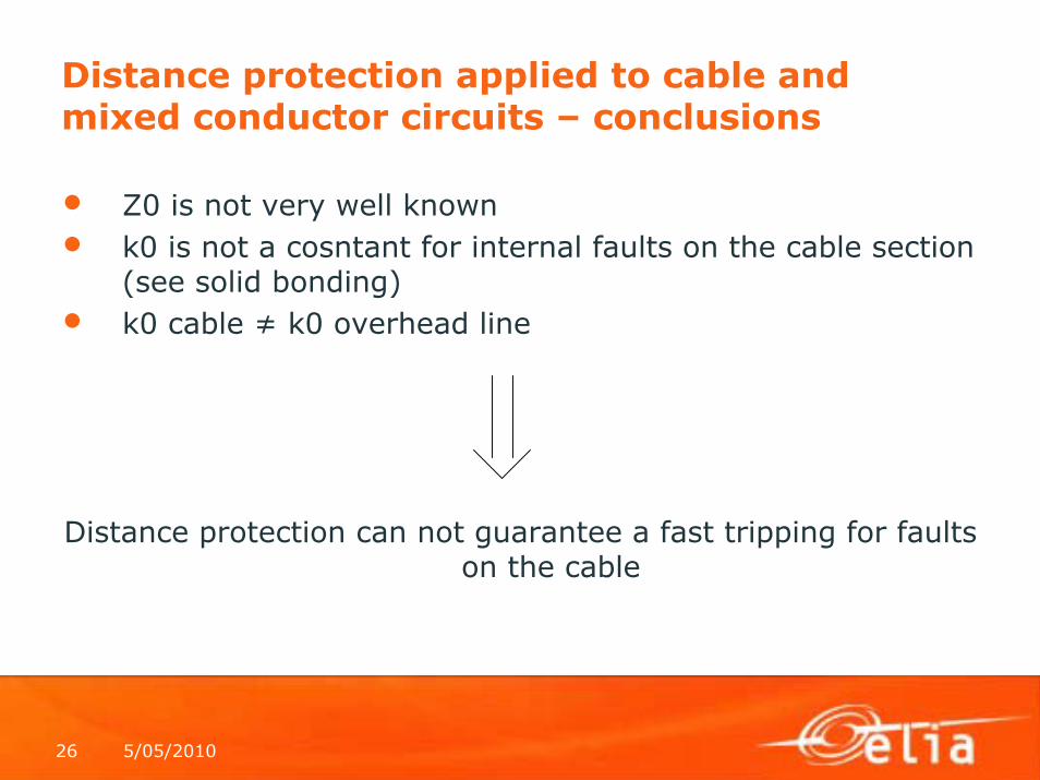
Distance protection applied to cable and mixed conductor circuits – conclusions
• Z0 is not very well known• k0 is not a cosntant for internal faults on the cable section
(see solid bonding)• k0 cable ≠ k0 overhead line
Distance protection can not guarantee a fast tripping for faultson the cable

5/05/201027
Application of distance protection withteleprotection
• Benefits• Usual benefits :
– Instantaneous trip of all faults between both ends;– Good sensitivity for high resistance faults
• Benefits associated with mixed conductors circuits– The uncertainty associated with the k0 factor
disappears• Drawbacks
• Necessity to have a communication• All classical schemes are available :
• Permissive schemes (under and overreach)• Blocking schemes
Overreach schemes give advantage over underreachschemes : due to the low serie impedance of the cable, itis easier to set an overreach zone

5/05/201028
Application of distance protection withteleprotection - POTT
Z1 (t=0)
Z2 (t2≠0)
Z1 (t=0)
Z2 (t2≠0)
Ztpr
Ztpr
E E
R R
& &
Z Tpr Z Tpr
Other zonesZ1-t1, Z2-t2, Z3-t3≥1 ≥1
Other zonesZ1-t1, Z2-t2, Z3-t3
trip trip
5/05/201029
Application of distance protection withteleprotection - pros and cons
Pros : • Less dependent on cable characteristics then distance
protection without teleprotection;• Very good selectivity• Low bandwidth requirement for the communication channel
(in comparison to current differential protection)Cons :
• Dependent on communication channel for the teleprotection• Lower sensitivity then current differential

5/05/201030
Application of current differential protection
• Principle : Kirchoff law
• Trip characteristic
• Protection is stabilized against : • Errors due to CTs• CT saturation• Errors in the measurements made by the relay• Charging current in the underground cable
0II BA =+
Idiff
Ires
Trip
RestrainId min
BA
BAdiff
IIIrestrain
III
+=
+=

5/05/201031
Application of current differential protection -pros and cons
Pros : • Good sensitivity;• Less dependent on cable characteristics then distance
protection;• Very good selectivity
Cons : • No back up protection• Totally dependent on communication channel

5/05/201032
Application of phase comparison protectionPrinciple : • Phase angle comparison between the currents at both ends• When phase angle difference is above the level, there is a trip
External fault
Internal fault
A B
87L 87LCommunication link
IBIA
Trip1Trip1

5/05/201033
Application of phase comparison protection -pros and cons
Pros : • Less dependent on cable characteristics then distance
protection;• Very good selectivity• Low bandwidth requirement for the communication channel
(in comparison to current differential protection)• Less sensibility regarding CT saturation (in comparison to
current differential protection)Cons :
• No back up protection• Totally dependent on communication channel• Lower sensitivity then current differential ?

5/05/201034
Communication channels
Dedicated optical fibers :• Immune to EMI, ground-potential rise : bit error rate is very
low• High bandwidth (very suitable for current differential
protections)• Direct optical interface on the protection relay• High reliability and availability• High security• Maintenance costs are low• Investment for the communication link is comparable to
classic twisted copper pairs• Not cost effective if hired optical fibers (low use of the
available bw especially in case of teleprotection)

5/05/201035
Communication channels - continued
Multiplexed optical link• Immune to EMI, ground-potential rise : bit error rate is very
low• Bandwidth is a bit lower than direct optical fibers but still
very suitable for current differential protection• No direct interface on the protection relay• Reliability is lower than direct optical fibers due to the
presence of the mux/demux• High security• Maintenance costs are low• Cost effective if hired optical fibers (better use of the
available bw especially in case of teleprotection)

5/05/201036
Communication channels - continued
Dedicated twisted pair• Immunity to EMI, ground-potential rise is a problem; bit
error rate is higher• Risk of interferences with other pairs in the same cable• Low bandwidth (not very suitable for current differential
protections, suitable for teleprotection, phase comparison)• No direct interface on the protection relay• Low security• Interesting only if the twisted pair is existing; otherwise it is
better to install an optical fibers cable

5/05/201037
Communication channels - continued
Digital leased line• Immunity to EMI, ground-potential rise is an issue; bit error
rate is higher• Medium bandwidth• Not very suitable for current differential protection because
transmission delays from A to B and B to A could bedifferent
• Evolution of telecommunication networks is towards IP : thismeans possible variations on the transmission delay;
• No direct interface on the protection relay• Reliability, security are questionable
5/05/201038
Communication channels - continued
Power Line Carrier
PLC is usable on mixed conductor circuits but :
• Signal loss is higher than for OHL
• Signal losses due to the different characteristic impedances forthe cable and the overhead line

5/05/201039
Mixed conductors circuits - autorecloseon OHL are non-permanent
Majority of faultson cable are permanent
=> The ideal solution is AR for faults on OHL and no AR for faults oncable
Different factors shall be taken into account : • Short-circuit widhstand of the cable (conductor – external fault, conductor
+ shield – internal fault) ?• Ratio OHL – underground cable for the circuit ?• Safety for people (no AR gives the highest safety)• Cost for a dedicated protection system on the cable (to discriminate a fault
on the cable section) : installation, maintenance• Continuity of service• Power quality• Operation of the network• Non – availability of the circuit (use of a dedicated protection on the cable
section will reduce the duration of the interruption in case of a fault)

5/05/201040
Mixed conductors circuits - autoreclose
Questions : • AR or not ?
• 1-ph, 3-ph or both ?• If AR, with or without blocking for fault on the cable ?
If blocking, with or without protection relay at the transition between OHL and cable ?

5/05/201041
Protection to discriminate a fault on the cablesection - With protection at the transition
• Cable differential protection• Phase comparison protection• Distance protection with communication scheme : normally not
used because it requires VT’s at the transition

5/05/201042
Protection to discriminate a fault on the cablesection - Without protection at the transition
Possible for 2-ends configurations and with the cable at one end of the circuit :
End A : • Z1 covers the whole cable (a bit further) without delay;
trips CB at A, blocks AR at A; sends remote tripping to B, sends blocking to AR at B;
• Z2 covers 80% of the circuit (cable + OHL)without delay; trips CB at A, start AR at A
• Z3, Z4 as usualEnd B :
• Z1 covers 80% of the OHL; trips CB at B, starts AR at B; sends remote tripping to A and start AR at A
• Z2 covers the busbar at A

5/05/201043
AR without blocking• Example : short siphon
• The probability to have a fault on the cable is low because the lengthof the cable is short
• Impossibility to discriminate a fault on the cable without protection at the transition
• Very high costs associated with the communication link to the siphon• Constraints for the cable (example Elia : main 1 and main 2 protection)
Voltage (kV) Base (ms) Main 1 or main 2 doesn't work
(ms)
Communication link fails
(ms)
380 100 100 100220 120 120 400150 120 120 400
Voltage (kV) Internal fault with AR - conductor +
shield (ms)
Permanent external fault with
AR - conductor (ms)
380 100 + 100 100 + 100220 120 + 400 120 + 400150 120 + 400 120 + 400
Maximum allowed time to eliminate the fault
Maximum constraint for the cable
Conclusion :
•Cable conductor shall bedimensioned for a permanent external fault; absence of blocking has no impact;
•Cable sheath shall bedimensioned for a permanent internal fault; absence of blockingwill increase the time duration of the fault current in the sheath

5/05/201044
ExampleProtections for the circuit (at each end): • Main 1 : distance protection with POTT; Main 2 : current differential protectionCable fault discrimination to block the AR : • Current differential protection
Blo
ck A
R
Blo
ck A
R

5/05/201045
Design of the transition
• CT : usually ring CT’s• Electronic equipments are installed in cabinet :
• Heating• Ventilation (preferably natural)• Good isolation (internal temperature ≤ 55 °C
• Power supplyModern relays require DC power supply; this means a battery + charger and a source to feed the charger; different possibilities :
• LV connection to an utility : + : easy from a technical point of view;- : high cost if the distance to the utility’s network is high
• VT :+ : cost is usually lower than a connection to an utility- : maintenance cost
• Other possibilities : windturbine, solar cels

5/05/201046
Design of the transition – power supply
Examples :

5/05/201047
Power supply - sizing• Loads
Digital protection relay => permanent load : ca 20 W (DC via battery)
Heating of the cabinet : ca 100 W (AC)
• Required autonomy for the batteryAs high as possible because availability of the source is far from guaranteed :
• Windturbine, solar cels don’t work permanently• VT : not available during maintenance of the circuit• LV network : not available during works
But the autonomy is limited by the source that will charge the battery(excepted for LV network) :
• VT : standard is 1000 VA, 10 kVA with special VT• Windturbine, solar cels : a few hundreds VA
• Possible solution

5/05/201048

5/05/201049

5/05/201050
Charger + battery

5/05/201051

5/05/201052

5/05/201053
Policy regarding AR and necessity to discriminatea fault on the cable section – Elia’s example
3-ended circuit with a transformer tap at one end connected with an underground cable
• Autoreclose• Dedicated current differential
protection on the cable to blockthe autoreclose at all ends in case of a fault on the cable
• Reason : importance to restorethe interconnection between A and B as soon as possible in case of fault on the cable
General : underground cables are dimensioned to widhstandAR on fault (internal and external, conductor and sheath)

5/05/201054
Policy regarding AR – Elia’s example
• L<1 km : AR without blocking for fault on the cableReason : low risk for fault on the cable section
• L<40% of the circuit :• AR• Dedicated current differential protection on the cable to block the
autoreclose at all ends in case of a fault on the cableReason : number of faults on the OHL > number faults on the cable
• L>40% of the circuit and [interconnection or industrial customer]• AR• Dedicated current differential protection on the cable to block the
autoreclose at all ends in case of a fault on the cableReason : importance of the circuit
• L>40% of the circuit and [nor interconnection & nor industrial customer]• No AR
Reason : less importance of the circuit
A BL

5/05/201055
Policy regarding AR – Elia’s example
• L<1 km : • AR without blocking
Reason : probability to have a fault on the cable is low• L>1 km and [interconnection or industrial customer]
• AR• Dedicated current differential protection on the cable to block the
autoreclose at all ends in case of a fault on the cableReason : importance of the circuit
• L>1 km and [nor interconnection & nor industrial customer]• AR without blocking
Cost to implement a dedicated protection for fault on the cable is high
5/05/201056
References
• Electrical Transmission and Distribution Reference Book –Westinghouse Electric Corporation, 1964
• Protection of High-Voltage AC Cables – Demetrios A. Tziouvaras, Schweitzer Engineering Laboratories
• Cigre Working Group B5.23 – Technical Brochure “Short circuit protection of circuits with mixed conductor technologies in transmission networks” (to be published in 2012)