IEEE BSEE, MBAieee.rackoneup.net/rrvs/09/Ferrite Cores - The Rest of the Story.pdf · Curtis White...
48
IEEE Presentation October 29 2009 October 29, 2009 Curtis White BSEE, MBA 1
Transcript of IEEE BSEE, MBAieee.rackoneup.net/rrvs/09/Ferrite Cores - The Rest of the Story.pdf · Curtis White...

IEEE PresentationOctober 29 2009October 29, 2009Curtis White BSEE, MBA
1

Most figures taken from Fair‐Rite catalogs (13th and 14th editions)Very similar material available from competing vendors
2

Ferrite properties often misunderstood or insufficiently understood by designersResults are often costly redesigns and program delays
3

Transformers (primaril in higher freq enc Transformers (primarily in higher frequency switching mode power supplies) and inductorsinductorsTypically many turns on various core shapes
Frequency dependent “resistors” (losses) ( i il i EMC t l)(primarily in EMC control)Typically few turns using sleeve or toroid
4

fFerrite has many formulations having different properties for example:
Manganese (Mn) – e.g. grade 85 used primarily for transformers with µi of 900Manganese zinc (MnZn) – e.g. grade 73 used for transformers, g ( ) g g 73 ,inductors and EMC suppression at low frequencies with µi of 2500 Nickel zinc (NiZn) – e.g. grade 43 used primarily for EMC suppression at medium and higher frequencies with µi of 850g q µi 5Nickel zinc (NiZn )– e.g. grade 61 used primarily for EMC suppression at higher frequencies with µi of 125
5

fHuge variety of shapes and sizes available▪ E and I▪ Toroids▪ Toroids▪ Cup cores▪ Rods▪ Sleeves▪ Beads▪ etc▪ Custom
6

Initial permeability – from about 20 to over 10,000Some highly conductive (MnZi) (50Ω cm)Some highly conductive (MnZi) (50Ω cm)Some highly resistive (NiZn) (1x 10⁷ Ω cm)Curie temperature from 120 to > 500 °cpSome have dimensional resonance frequencies (MnZi) and may crack or shatter if excited at these f ifrequencies
7

Inductance and coupling (permeability)p g (p y)Losses (core and winding)Saturation (loss of most of inductance)Capacitance effects on bandwidthTemperature rise
l f dCurie temperature (loss of inductive properties)Physical damage
Di i l ( ki )Dimensional resonance (core cracking)Size, weight and cost (application driven issues)Others (tolerances skin effect and proximity effect)Others (tolerances, skin effect and proximity effect)
8

Formulas Designer o u astypically presented do not consider many key
es g emust address additional factorsmany key
parametersfactors
9

Serious design problems often result from ignorance or neglect of several propertiesignorance or neglect of several propertiesComplex permeability of ferritesCapacitance effectsCapacitance effectsTemperature effectsP t ti l ki t di i l Potential core cracking at dimensional resonance frequenciesOthers (less common)Others (less common)
10

Not Really Hard to UnderstandCan Cause Major Problemsj
11

C l bilit f f it i k t Complex permeability of ferrites is a key to proper ferrite core application designC id i l th i iti l ff ti Considering only the initial or effective permeability can result in serious problems
12
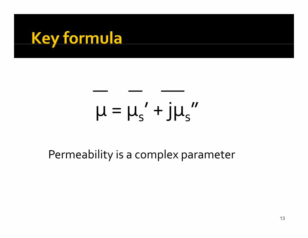
’ j ”µ = µs’ + jµs”
Permeability is a complex parameter
13

µ = µ ’ + jµ ”µ = µs + jµs
Imaginary part relates to loss properties and is highly frequency
Real part relates to inductive properties and is highly frequency highly frequency
dependentg y q y
dependent
14

Several component properties are typically included in µ”included in µHysteresisEddy CurrentsEddy CurrentsResidual lossesOthers and UnknownsOthers and Unknowns
15

µ ’ and µ ” are measurable and often µs and µs are measurable and often providedMeasurement requires RF instrumentationMeasurement requires RF instrumentation
16

.
Rapid rise in losses
Constant initial permeability
Rapid loss f
Ferrimagnetic resonance at
of permeability
500 kHz
17

Ferrimagneticresonance at2 MHz
18

FerrimagneticFerrimagnetic resonance at 20 MHz
19

Good
Good variable resistance (loss) region for EMC
transformer design region –low losses and
high real component of
g
component of permeability
Two basic modes of application for ferrites
20
ferrites

For a given component:Z = jωLs+ Rs = jωLo(µs’ + jµs”) ohmWhere Lo = air core inductance
Then:ωLs = ωLoµs’ ohm (inductive reactance part)s oµs pRs = ωLoµs” ohm (resistive – loss part)
21

Employ formulas from prior slide (and other Employ formulas from prior slide (and other references)Developing EXCEL© tool for this purposeDeveloping EXCEL© tool for this purpose
22

CALCULATED CORE IMPEDANCE OF 1T ON P/N 2643250402 USING TYPE 43 MATERIAL & CALCULATED SHUNT CAPACITANCE OF 0.779 pF
140
160
180
200
GROSS Z
60
80
100
120
OH
MS RESISTANCE
REACTANCE
0
20
40
0.01 0.10 1.00 10.00 100.00 1000.00
23
MHz

fInductance is frequency dependent especially near and above ferrimagnetic resonanceAs shown µs’ rises and drops rapidly Therefore inductance drops rapidlyTransformers and inductors may essentially cease to function as planned in this region
24

INDUCTANCE VERSUS FREQUENCY
1 0E 05
1.2E-05
INDUCTANCE VERSUS FREQUENCY
8.0E-06
1.0E-05
NR
YS
4.0E-06
6.0E-06
UC
TAN
CE
IN H
E
0 0E 00
2.0E-06
IND
U
25
0.0E+001.E+04 1.E+05 1.E+06 1.E+07 1.E+08 1.E+09
FREQUENCY

“R i ” i l f d d i ll d “Resistance” is also frequency dependent especially near and above ferrimagnetic resonance
As shown µs” rises dramatically As shown µs rises dramatically Therefore “resistance” increases rapidly
Components become frequency dependent “resistors”Very useful in EMC applicationsDissipation of undesired signals is goal
Watch dissipation levels resulting from signals in this high Watch dissipation levels resulting from signals in this high loss frequency range
26

200
CALCULATED CORE IMPEDANCE OF 1T ON P/N 2643250402 USING TYPE 73 MATERIAL & CALCULATED SHUNT CAPACITANCE OF 1.74 pF
140
160
180
200
80
100
120
OH
MS RESISTANCE
0
20
40
60
27
00.01 0.10 1.00 10.00 100.00 1000.00
MHz

Winding capacitance effects often very significantWinding capacitance effects often very significantInformation on calculation hard to find
28

Winding capacitance shunts desired inductanceNon‐conductive ferrite adds minimal capacitance (but windings do have self capacitance to
id )consider)Conductive cores act like capacitor plates and significantly increase capacitance and its significantly increase capacitance and its undesired effects
Stray capacitance to surroundings may also be of concern y p g y(beyond our scope tonight)
29

Models are elusive (out of scope for tonight)Non conductive model by Medhurst (1947) based Non‐conductive model by Medhurst (1947) based upon empirical measurements of many air core inductors and quoted by Snelling in his bookq y gConductive core model (one) by Duerdoth (1946) and also quoted by Snelling in his bookq y g
Newer models may exist
30

CALCULATED CORE IMPEDANCE OF 1T ON P/N 2643250402 USING TYPE
200
73 MATERIAL & CALCULATED SHUNT CAPACITANCE OF 1.74 pF
140
160
180
80
100
120
OHM
S
GROSS Z
NET Z with C
20
40
60
31
00.01 0.10 1.00 10.00 100.00 1000.00
MHz

CALCULATED CORE IMPEDANCE OF 10T ON P/N 2643250402 USING TYPE 73 MATERIAL & CALCULATED SHUNT CAPACITANCE OF 17 401 pF
20000
73 MATERIAL & CALCULATED SHUNT CAPACITANCE OF 17.401 pF
12000
14000
16000
18000
6000
8000
10000
12000
OHM
S
GROSS Z
NET Z with C
0
2000
4000
6000
32
0.01 0.10 1.00 10.00 100.00 1000.00MHz

200
CALCULATED CORE IMPEDANCE OF 1T ON P/N 2643250402 USING TYPE 43 MATERIAL & CALCULATED SHUNT CAPACITANCE OF 0.779 pF
140
160
180
200
80
100
120
OHM
S
GROSS Z
NET Z with C
0
20
40
60
33
00.01 0.10 1.00 10.00 100.00 1000.00
MHz

CALCULATED CORE IMPEDANCE OF 10T ON P/N 2643250402 USING TYPE
20000
43 MATERIAL & CALCULATED SHUNT CAPACITANCE OF 0.779 pF
14000
16000
18000
8000
10000
12000
OHM
S
GROSS Z
NET Z with C
2000
4000
6000
34
00.01 0.10 1.00 10.00 100.00 1000.00
MHz

Be sure to investigate these issues
35

f fMust carefully watch ferrite core temperatureAmbient levelsRise due to core and wire lossesDissipation of harmonic content in high loss range
Temperature significantly effects permeability and impedanceCurie temperature is definite limit for applications
36

Curie temperature of
150 °C
37
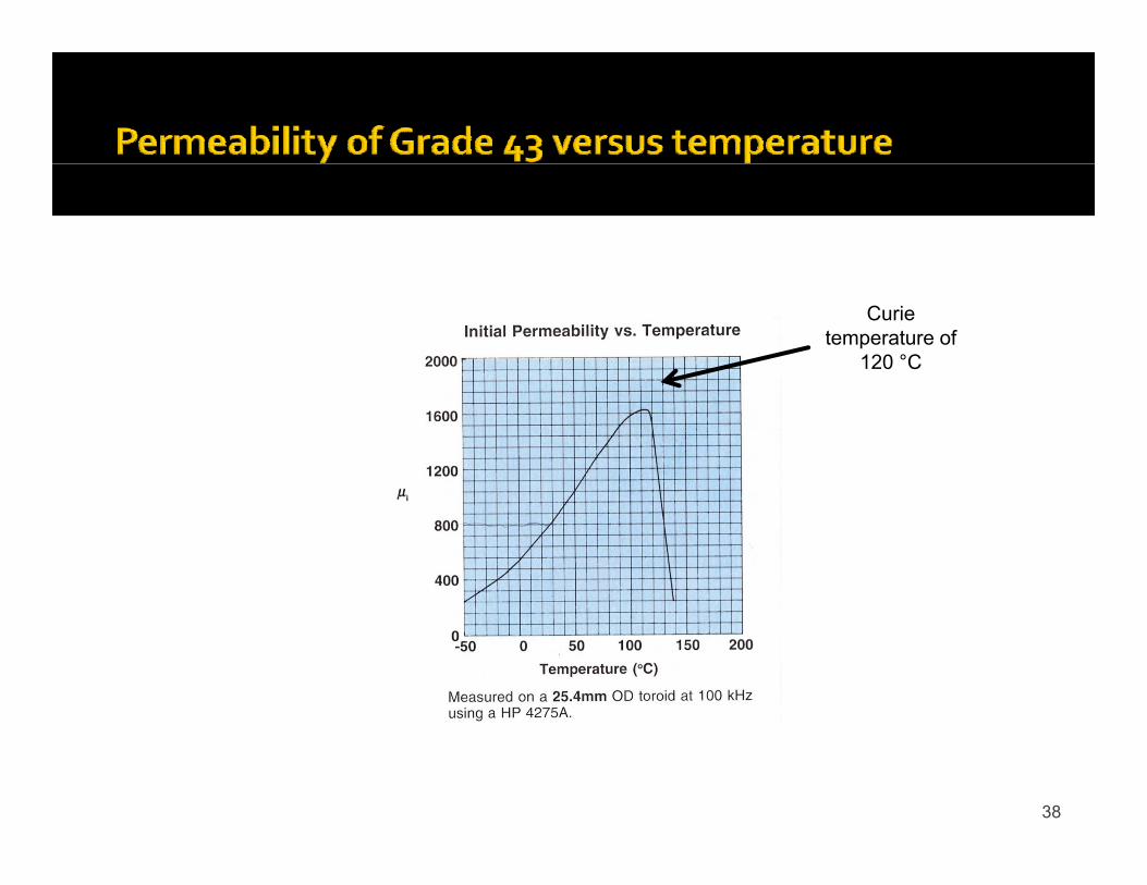
Curie temperature of
120 °C
38

Curie temperature of
400 °C
39

High temperatures lower Z dramaticallydramatically
Even though µi increases with temperature z goes down Material
dependent propertyproperty
40

fTemperature will result in significant change in permeability and impedanceVery large changes are likelyVirtual total permeability loss is possible (Curie temperature exceeded)Physical damage or destruction is possible
fConsider all factors and know where you areAccount for changes and tolerances (+/‐ 20%)
41

Uncommon but serious problem
42

fDimensional resonant frequency is related to product of permeability and conductivity
l l h h d d h hSimultaneously high conductivity and high permeability cores may experience
l f kresonances at quite low frequencies (kHz)Resonance may result in cracking or h fshattering of cores
43

G ll l li t M Zi f Generally only applies to MnZi cores of moderate sizeF /( *(( *OD) ( *ID)/ ))FMR = 5700/(π*((10*OD)+(10*ID)/2))
44

Calculate frequencies for high permeability high conductivity cores (MnZi)Compare resonant frequencies to expected excitation frequenciesChange core material or size if necessary to avoid problems
45

Incorporate complex permeability issues into designsStay in high permeability low loss region for most transformers and inductors (considering relevant frequencies)Select cores for maximum loss at undesired frequencies Select cores for maximum loss at undesired frequencies for EMC applications
Watch maximum temperatures in applicationIf i M Zi b l t t di i l If using MnZi cores be alert to dimensional resonances
46

Fair‐Rite Soft Ferrites, 13th Edition, 1998, Fair‐Rite Products Corporation, Wallkill, NY.Corporation, Wallkill, NY.Fair‐Rite Soft Ferrites, 14th Edition, 2000, Fair‐Rite Products Corporation, Wallkill, NY.Soft Ferrites Properties and Applications 2nd Edition Soft Ferrites, Properties and Applications, 2nd Edition, 1988, Snelling, E. C., Butterworths, Stoneham, MA.Soft Ferrites 1998 Data Handbook MA01, 1998, Phillips Electronics NV, The Netherlands.
47

Speak up
48