IEEE 1 Single-Carrier SM-MIMO: A Promising Design for...
33
1553-877X (c) 2015 IEEE. Personal use is permitted, but republication/redistribution requires IEEE permission. See http://www.ieee.org/publications_standards/publications/rights/index.html for more information. This article has been accepted for publication in a future issue of this journal, but has not been fully edited. Content may change prior to final publication. Citation information: DOI 10.1109/COMST.2016.2533580, IEEE Communications Surveys & Tutorials IEEE 1 Single-Carrier SM-MIMO: A Promising Design for Broadband Large-Scale Antenna Systems Ping Yang, Yue Xiao, Yong Liang Guan, Member, IEEE , K. V. S. Hari, Fellow, IEEE , A. Chockalingam, Senior member, IEEE , Shinya Sugiura, Senior member, IEEE , Harald Haas, Member, IEEE , Marco Di Renzo, Senior member, IEEE , Christos Masouros, Senior member, IEEE , Zilong Liu, Lixia Xiao, Shaoqian Li, Fellow, IEEE , and Lajos Hanzo, Fellow, IEEE Abstract —The main limitations of employing large- scale antenna (LSA) architectures for broadband frequency-selective channels include, but are not lim- ited to their complexity, power consumption and the high cost of multiple radio frequency (RF) chains. Promising solutions can be found in the recently pro- posed family of single-carrier (SC) spatial modulation (SM) transmission techniques. Since the SM scheme’s transmit antenna (TA) activation process is carried out in the context of a SC-SM architecture, the benefits of a low-complexity and low-cost single-RF transmitter are maintained, while a high MIMO multiplexing gain can be attained. Moreover, owing to its inherent SC structure, the transmit signals of SC-SM have attrac- tive peak power characteristics and a high robustness to RF hardware impairments, such as the RF carrier frequency offset (CFO) and phase noise. In this paper, we present a comprehensive overview of the latest P. Yang, Y. Xiao, L. Xiao and S. Li are with the National Key Laboratory of Science and Technology on Communications, University of Electronic Science and Technology of China 611731, Sichuan, China. (e-mail: [email protected], [email protected], [email protected], [email protected]). K. V. S. Hari and A. Chockalingam are with the Department of ECE, Indian Institute of Science, India (e-mail: hari, achock- [email protected]). Harald Haas is with the Institute for Digital Communications and the Joint Research Institute for signal and Image Processing, School of Engineering, The University of Edinburgh, U. K. (e-mail: [email protected]). Marco Di Renzo is with the Laboratory of Signals and Systems (L2S), French National Center for Scientific Research (CNRS), U- niversity of Paris-Sud XI, 3 rue Joliot-Curie, 91192 Gif-sur-Yvette, France(e-mail: [email protected]). Y. Guan and Z. Liu are with the School of Electrical and Electronic Engineering, Nanyang Technological University, Singapore (e-mail: EYLGuan,[email protected]). S. Sugiura is with the Department of Computer and Information Sciences, Tokyo University of Agriculture and Technology, Koganei, Tokyo 184-8588, Japan (e-mail: [email protected]). Christos Masouros is with the Communications and Information Systems research group, Dept. Electrical & Electronic Engineering, University College London (e-mail: [email protected]). L. Hanzo is with the School of Electronics and Computer Sci- ence, University of Southampton, Southampton SO17 1BJ, U.K. (e- mail:[email protected]). The financial support of the National Science Foundation of China under Grant number 61501095, of the National High-Tech R&D Pro- gram of China (“863” Project under Grant number 2014AA01A707), of the European Research Council’s Advanced Fellow Grant, of the Royal Academy of Engineering, UK and the Engineering and Physical Sciences Research Council (EPSRC) project EP/M014150/1, and of the National Science Foundation of China under Grant number 60902026 and 61032002, and of the Japan Society for the Promotion of Science (JSPS) KAKENHI Grant Number 26709028 are gratefully acknowledged. research achievements of SC-SM, which has recently attracted considerable attention. We outline the as- sociated transceiver design, the benefits and potential tradeoffs, the LSA aided multiuser (MU) transmission developments, the relevant open research issues as well as the potential solutions of this appealing transmission technique. Index Terms—Energy Efficiency, frequency selective channels, large-scale MIMO systems, spatial modula- tion, single-carrier transmission, single-RF chain, mul- tiuser communication. I. Introduction M ULTIPLE-input multiple-output (MIMO) tech- niques have been widely studied during the last two decades and have been incorporated into most of the recent communication standards [1], [2] due to their benefits of providing diversity, and/or multiplexing gains [3]–[5]. However, in order to satisfy the ever-growing de- mands for higher capacity, larger coverage area and better reliability, further improved MIMO transceivers should be designed [6]. Pursuing this research objective, the concept of large- scale MIMO (LS-MIMO) techniques has been proposed [6]–[12], which employs tens to hundreds of trans- mit/receive antennas for dramatically improving the at- tainable link reliability, spectral efficiency and cellular coverage. Usually, the multiple-antenna front-end archi- tecture requires a separate radio frequency (RF) chain. This means that the cost of MIMO transmitters to scale linearly with the number of antennas [13]. Moreover, the presence of hundreds of antennas will increase the complexity of both the transmit signal generation and detection. Furthermore, the RF power amplifiers and the associated high-dimensional signal processing may erode the energy efficiency of systems, which are responsible for about 55-85% of the total power consumption [14], [15]. These factors exacerbate the practical realization of LS- MIMO systems. The emerging SM design paradigm constitutes an at- tractive low-complexity yet energy-efficiency option for the family of LS-MIMO systems, due to its low-cost single-RF- based transmitter, as well as owing to its low-complexity single-stream based detector and its ability to maintain the potential benefits of multiple antennas [16]–[19]. The roots of the SM design philosophy can be traced back
Transcript of IEEE 1 Single-Carrier SM-MIMO: A Promising Design for...

1553-877X (c) 2015 IEEE. Personal use is permitted, but republication/redistribution requires IEEE permission. See http://www.ieee.org/publications_standards/publications/rights/index.html for more information.
This article has been accepted for publication in a future issue of this journal, but has not been fully edited. Content may change prior to final publication. Citation information: DOI 10.1109/COMST.2016.2533580, IEEECommunications Surveys & Tutorials
IEEE 1
Single-Carrier SM-MIMO: A Promising Design forBroadband Large-Scale Antenna Systems
Ping Yang, Yue Xiao, Yong Liang Guan, Member, IEEE , K. V. S. Hari, Fellow, IEEE ,A. Chockalingam, Senior member, IEEE , Shinya Sugiura, Senior member, IEEE , Harald Haas, Member,
IEEE , Marco Di Renzo, Senior member, IEEE , Christos Masouros, Senior member, IEEE ,Zilong Liu, Lixia Xiao, Shaoqian Li, Fellow, IEEE , and Lajos Hanzo, Fellow, IEEE
Abstract—The main limitations of employing large-scale antenna (LSA) architectures for broadbandfrequency-selective channels include, but are not lim-ited to their complexity, power consumption and thehigh cost of multiple radio frequency (RF) chains.Promising solutions can be found in the recently pro-posed family of single-carrier (SC) spatial modulation(SM) transmission techniques. Since the SM scheme’stransmit antenna (TA) activation process is carried outin the context of a SC-SM architecture, the benefits ofa low-complexity and low-cost single-RF transmitterare maintained, while a high MIMO multiplexing gaincan be attained. Moreover, owing to its inherent SCstructure, the transmit signals of SC-SM have attrac-tive peak power characteristics and a high robustnessto RF hardware impairments, such as the RF carrierfrequency offset (CFO) and phase noise. In this paper,we present a comprehensive overview of the latest
P. Yang, Y. Xiao, L. Xiao and S. Li are with the NationalKey Laboratory of Science and Technology on Communications,University of Electronic Science and Technology of China 611731,Sichuan, China. (e-mail: [email protected], [email protected],[email protected], [email protected]).
K. V. S. Hari and A. Chockalingam are with the Departmentof ECE, Indian Institute of Science, India (e-mail: hari, [email protected]).
Harald Haas is with the Institute for Digital Communicationsand the Joint Research Institute for signal and Image Processing,School of Engineering, The University of Edinburgh, U. K. (e-mail:[email protected]).
Marco Di Renzo is with the Laboratory of Signals and Systems(L2S), French National Center for Scientific Research (CNRS), U-niversity of Paris-Sud XI, 3 rue Joliot-Curie, 91192 Gif-sur-Yvette,France(e-mail: [email protected]).
Y. Guan and Z. Liu are with the School of Electrical and ElectronicEngineering, Nanyang Technological University, Singapore (e-mail:EYLGuan,[email protected]).
S. Sugiura is with the Department of Computer and InformationSciences, Tokyo University of Agriculture and Technology, Koganei,Tokyo 184-8588, Japan (e-mail: [email protected]).
Christos Masouros is with the Communications and InformationSystems research group, Dept. Electrical & Electronic Engineering,University College London (e-mail: [email protected]).
L. Hanzo is with the School of Electronics and Computer Sci-ence, University of Southampton, Southampton SO17 1BJ, U.K. (e-mail:[email protected]).
The financial support of the National Science Foundation of Chinaunder Grant number 61501095, of the National High-Tech R&D Pro-gram of China (“863” Project under Grant number 2014AA01A707),of the European Research Council’s Advanced Fellow Grant, of theRoyal Academy of Engineering, UK and the Engineering and PhysicalSciences Research Council (EPSRC) project EP/M014150/1, andof the National Science Foundation of China under Grant number60902026 and 61032002, and of the Japan Society for the Promotionof Science (JSPS) KAKENHI Grant Number 26709028 are gratefullyacknowledged.
research achievements of SC-SM, which has recentlyattracted considerable attention. We outline the as-sociated transceiver design, the benefits and potentialtradeoffs, the LSA aided multiuser (MU) transmissiondevelopments, the relevant open research issues as wellas the potential solutions of this appealing transmissiontechnique.
Index Terms—Energy Efficiency, frequency selectivechannels, large-scale MIMO systems, spatial modula-tion, single-carrier transmission, single-RF chain, mul-tiuser communication.
I. Introduction
MULTIPLE-input multiple-output (MIMO) tech-niques have been widely studied during the last
two decades and have been incorporated into most ofthe recent communication standards [1], [2] due to theirbenefits of providing diversity, and/or multiplexing gains[3]–[5]. However, in order to satisfy the ever-growing de-mands for higher capacity, larger coverage area and betterreliability, further improved MIMO transceivers should bedesigned [6].
Pursuing this research objective, the concept of large-scale MIMO (LS-MIMO) techniques has been proposed[6]–[12], which employs tens to hundreds of trans-mit/receive antennas for dramatically improving the at-tainable link reliability, spectral efficiency and cellularcoverage. Usually, the multiple-antenna front-end archi-tecture requires a separate radio frequency (RF) chain.This means that the cost of MIMO transmitters to scalelinearly with the number of antennas [13]. Moreover,the presence of hundreds of antennas will increase thecomplexity of both the transmit signal generation anddetection. Furthermore, the RF power amplifiers and theassociated high-dimensional signal processing may erodethe energy efficiency of systems, which are responsible forabout 55-85% of the total power consumption [14], [15].These factors exacerbate the practical realization of LS-MIMO systems.
The emerging SM design paradigm constitutes an at-tractive low-complexity yet energy-efficiency option for thefamily of LS-MIMO systems, due to its low-cost single-RF-based transmitter, as well as owing to its low-complexitysingle-stream based detector and its ability to maintainthe potential benefits of multiple antennas [16]–[19]. Theroots of the SM design philosophy can be traced back

1553-877X (c) 2015 IEEE. Personal use is permitted, but republication/redistribution requires IEEE permission. See http://www.ieee.org/publications_standards/publications/rights/index.html for more information.
This article has been accepted for publication in a future issue of this journal, but has not been fully edited. Content may change prior to final publication. Citation information: DOI 10.1109/COMST.2016.2533580, IEEECommunications Surveys & Tutorials
IEEE 2
to the combination-based frequency hopping code divisionmultiple access technique (FH-CDMA) proposed in 1980[20]–[22], where the combination pattern of the frequencybins was used for conveying information, hence resultingin an improved throughput. The first conference paper onsingle-RF based SM was published in 2006 [23], but itsextensive research was mainly fueled by the pioneeringworks of Haas et al. [16]–[18], Mesleh et al. [16], [24], [25],followed by Yang et al. [26], Sugiura et al. [27], Renzoet al. [28]–[32], Panayırcı and Poor et al. [33], Başar[34], Chang et al. [35], [36] as well as Jeganathan et al.[37]. Throughout its decade-long history, the SM concepthas been termed in different ways and it was extended todifferent scenarios. The wide-ranging studies disseminatedin [23]–[42] have characterized some of the fundamentalproperties of SM. For example, the attainable bit error rate(BER) performance in different fading channels [23], [29]–[32], [37]–[39], the issues of achieving transmit diversity[27], [28], [31], [40], the effects of channel estimation errors[32], [41], [42], as well as the effects of power imbalance[43] have been characterized. Moreover, some simplifiedand generalized SM schemes have also been proposed byexploiting the different degrees of freedom offered by thetemporal domain, frequency domain and spatial domainfading [17]–[19], [27], such as the space shift keying (SSK),the generalized SSK (GSSK), the generalized SM (GSM),the space-time shift keying (STSK), the space-frequencyshift keying (SFSK) and the space-time-frequency shiftkeying (STFSK) arrangements. It was found that SMand its variants are capable of striking a flexible trade-off amongst the computational complexity imposed, thenumber of RF chains required, the attainable BER andthe achievable transmission rate.
To be specific, SM relies on the unique encoding philos-ophy of activating one out of numerous transmit antennas(TAs) during each channel-use [23]–[31]. The activated TAthen transmits classic complex-valued symbols of ampli-tude and phase modulation (APM). Since in SM only asingle TA is activated at any time instant, its transmittedsignal is sparse in the spatial domain. The advantages ofSM-MIMO include its low-dimensional signal representa-tion as well as reduced RF hardware complexity, cost,and size [18], [19]. Moreover, it is capable of relaxingthe requirement of inter-antenna synchronization and ofmitigating the inter-antenna interference of conventionalMIMO schemes. Apart from the earlier variants and exten-sions of SM disseminated in [17]–[19], recently a variety ofSM-related classes have been proposed, including those de-signed for spectrum sharing environments [44], for multipleaccess transmissions [45], for energy-efficient applications[46], for cooperative SM scenarios [47]–[53] and for closed-loop designs [54]. The above-mentioned potential benefitsof SM over the conventional MIMO techniques have beenvalidated not only via numerical simulations [16], [23],[29]–[32], [37]–[39] but also by laboratory experiments[55]–[57].
Despite of its rich literature [23]–[37], the family of SM-related schemes has been predominantly investigated in
Single Carrier-based SM-MIMO
Section I. Introduction
Background, Concept, Benefits and Challenges
Section II. System Model
A. Transmitter Design
B. Prefix Selection for SC-SM
C. An Example for SC-SM
D. Some Transmitter Design Variants
E. Detector Design
Section III. Potential Advantages
and Disadvantages
A. Potential Advantages
B. Some Tradeoffs and
Disadvantages
Section IV. SC-SM for Multiuser LS-
MIMO Systems
A. SC-based Transmission for LS-
MIMO Systems
B. SC-SM Large-Scale MIMO Designs
for Downlink Transmission
C. SC-SM Large-Scale MIMO Designs
for Uplink Transmission
D. Uplink SC-SM LS-MIMO System
Example and Performance Results
Section V. Further Design Issues
A. High-Speed Antenna Switching
B. Soft-Input Soft-Output Detector
Design
C. Further RF Chain Reduction
D. Practical Implementations
E. Adaptive Transceiver Design
F. Channel Estimation and Low-
Correlation Preamble Sequence
Design
Section VI. Conclusion
Fig. 1. Structure of this survey paper.
the context of flat fading channels. In the case of wide-band frequency-selective channels, orthogonal frequency-division multiplexing (OFDM) [58] is generally assumedin SM-related schemes. In this case, multiple TAs haveto be simultaneously activated over the OFDM frame,which will jeopardize most of the single-RF benefits ofSM-MIMO. Moreover, the OFDM signal has a high peak-to-average power ratio (PAPR), which may result in a lowpower amplifier efficiency [59]. Furthermore, the computa-tional burden of performing the discrete Fourier transform(DFT) of the OFDM scheme increases with the numberthe TAs. Due to these reasons, the OFDM-based SM(OFDM-SM) schemes [60] and the related variants maynot be suitable for the family LS-MIMO.
In recent years, the family of single-carrier (SC) or SC-like transmissions has become an interesting and promis-ing alternative for LS-MIMO, which can reduce the com-plexity imposed by the DFT and has a lower PAPRthan OFDM [61]–[64]. Moreover, as shown in [10], [65],the frequency-selective channel may be converted into afrequency-flat channel in LS-MIMO by carefully designedreceive filters and therefore SC-based scheme can be di-rectly used.
Motivated by the above-mentioned appealing charac-teristics of both SM and SC techniques shown in LS-MIMO transmissions, a flurry of research activities on SC-based SM (SC-SM) designs have been sparked off. In thispaper we provide an overview of the broadband SC-SMarchitecture, which has the potential of exploiting the jointadvantages of both SM and SC techniques. We summarizerecent results concerning this novel transmission technique

1553-877X (c) 2015 IEEE. Personal use is permitted, but republication/redistribution requires IEEE permission. See http://www.ieee.org/publications_standards/publications/rights/index.html for more information.
This article has been accepted for publication in a future issue of this journal, but has not been fully edited. Content may change prior to final publication. Citation information: DOI 10.1109/COMST.2016.2533580, IEEECommunications Surveys & Tutorials
IEEE 3
MIMO
channel
Input bits
MSM-
QAM/PSK
Active
antennaSpatial
modulation
Transmitter
Add
CP/ZP
RF
chain
1
2
tN
b
1b
2b l
q(k)s
……
q(k)e
Bits-to-Symbol Mapping
Input bits Active antenna BPSK symbol
00
01
10
11
1
2
1
2
-1
+1
-1
+1
SM with Nt=2 BPSK
1
2
rN
……
RF chain
RF chain
RF chain
RF chain
Remove
CP/ZP
Spatial
Demodulation
Time/Frequency
domain equalization P/S
Output
bits
Receiver
q(k)S/P 1)
x(
)k
x(
)K
x(
XSM symbols
Fig. 2. General transceiver structure of SC-SM systems.
and outline the associated transceiver design, as well as arange of potential solutions in the scenario of LS-MIMO,highlighting its impediments as well as its future researchdirections to consider.
A. OutlineThe remainder of this paper is organized as shown in
Fig. 1. Section II introduces the system model of theSC-SM technique and its relevant variants, emphasizingthe transmitter design, the prefix selection and variousdetector designs. In particular, both the time-domain andthe frequency-domain as well as the associated turboequalizers are investigated. The potential advantages anddisadvantages of the SC-SM scheme are summarized inSection III. In Section IV the applications of the SC-SM transceiver to LS-MIMO systems are presented, wheredifferent SC-SM designs conceived for the multiuser LS-MIMO uplink and downlink are reviewed. Section V high-lights a range of design issues that require more intensivestudy. Finally, Section VI concludes the paper.
B. NotationsThe following notations are employed throughout this
contribution. (·)T and (·)H denote the matrix transposeand Hermitian transpose, respectively. The probability ofan event is represented by p(·). Furthermore, ∥ · ∥ and| · | denote the Euclidean norm and magnitude operators,while U is the number of users, Ntot is the number ofantennas at the BS for its MU transmission and Nu is
the number of antennas at each user for their multiusertransmission. Furthermore, Nt and Nr are the number ofthe antennas at transmitter and receiver for their point-to-point transmission, respectively, while MSM, MVBLASTand MSTBC are the sizes of the PSK/QAM constellationused in SM, space time block code (STBC) and verticalBell labs layered space-time (VBLAST), respectively; K isthe length of the transmission frame; b is the transmittedbit vector; ei is the natural basis vector with only a singlenonzero element at ith position; L is the maximum channelimpulse response duration; ν is the length of the prefix ofthe transmit SC frame and x is the SM transmit symbolvector.
II. System Model of SC-SMA. Transmitter Design
In this section, we consider a broadband SC-SM basedMIMO system employing Nt TAs as well as Nr receiveantennas (RAs) and communicating over a frequency-selective fading channel, as depicted in Fig. 2. In a con-ventional narrowband SM scheme, the information bits areconveyed by the indices of the TAs as well as the classicAPM constellation (i.e. MSM-PSK/QAM). Specifically,one of the Nt TA elements is activated at each time slot bylog2(Nt) information bits, while one of MSM-APM symbolsis selected by another log2(MSM) information bits, whichwill be transmitted by the activated TA. In other words,the numbers of bits conveyed by the TA indices andAPM symbols are log2(Nt) and log2(MSM), respectively.
1553-877X (c) 2015 IEEE. Personal use is permitted, but republication/redistribution requires IEEE permission. See http://www.ieee.org/publications_standards/publications/rights/index.html for more information.
This article has been accepted for publication in a future issue of this journal, but has not been fully edited. Content may change prior to final publication. Citation information: DOI 10.1109/COMST.2016.2533580, IEEECommunications Surveys & Tutorials
IEEE 4
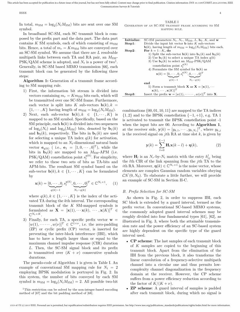
In total, mSM = log2(NtMSM) bits are sent over one SMsymbol.
In broadband SC-SM, each SC transmit block is com-posed by the prefix part and the data part. The data partcontains K SM symbols, each of which consisting of mSMbits. Hence, a total of mr = KmSM bits are conveyed overan SC-SM symbol. We assume that there are L resolvablemultipath links between each TA and RA pair, an MSM-PSK/QAM scheme is adopted, and Nt is a power of two1.Generally, in SC-SM based MIMO transmission [66], eachtransmit block can be generated by the following threesteps:
Algorithm 1: Generation of a transmit frame accord-ing to SM mapping rule.
1) First, the information bit stream is divided intovectors containing mr = KmSM bits each, which willbe transmitted over one SC-SM frame. Furthermore,each vector is split into K sub-vectors b(k), k ={1, · · · , K} having length of mSM = log2(NtMSM).
2) Next, each sub-vector b(k), k ∈ {1, · · · , K} ismapped to an SM symbol. Specifically, based on theSM principle, each b(k) is divided into two sequencesof log2(Nt) and log2(MSM) bits, denoted by b1(k)and b2(k), respectively. The bits in b1(k) are usedfor selecting a unique TA index q(k) for activation,which is mapped to an Nt-dimensional natural basisvector eq(k) ( i.e., e1 = [1, 0, · · · , 0]T ), while thebits in b2(k) are mapped to an MSM-APM (i.e.PSK/QAM) constellation point s
q(k)l . For simplicity,
we refer to these two sets of bits as TA-bits andAPM-bits. The resultant SM symbol based on thesub-vector b(k), k ∈ {1, · · · , K} can be formulatedby
x(k) = [0, · · · , 0︸ ︷︷ ︸q(k)−1
, sq(k)l , 0, · · · , 0︸ ︷︷ ︸
Nt−q(k)
]T ∈ CNt×1, (1)
where q(k), k ∈ {1, · · · , K} is the index of the acti-vated TA during the kth interval. The correspondingtransmit block of the K SM-mapped symbols isformulated as X = [x(1), · · · x(k), · · · , x(K)]T ∈CNt×K .
3) Finally, for each TA, a specific prefix vector w =[w(1), · · · · · · , w(ν)]T ∈ C1×ν , i.e. the zero-padding(ZP) or cyclic prefix (CP) vector, is inserted forpreventing the inter-block interference (IBI), whichhas to have a length larger than or equal to themaximum channel impulse response (CIR) durationL. Then, the SC-SM signal block and its prefixis transmitted over (K + ν) consecutive symbolsdurations.
The pseudo-code of Algorithm 1 is given in Table I. Anexample of conventional SM mapping rule for Nt = 2employing BPSK modulation is portrayed in Fig. 2. Inthis system, the number of bits conveyed by each SMsymbol is mSM = log2(NtMSM) = 2. All possible two-bit
1This restriction can be solved by the non-integer-based encodingmethod of [67] and the bit padding method of [68].
TABLE IGeneration of an SC-SM transmit frame according to SM
mapping rule.
Initialize: SC-SM parameters Nt, Nr, MSM, L, bI , K, and wStep1: Divide the input bit vector b into K sub-vectors
b(k), having length of mSM = log2(NtMSM) bits each.Step2: For k = 1 : K, do
1) Split the sub-vector b(k) into b1(k) and b2(k)2) Use b1(k) to select a unique TA index q(k)3) Use b2(k) to select an MSM-PSK/QAM
constellation point sq(k)l
4) Formulate the SM symbol for b(k) asx(k) = [0, · · · , 0︸ ︷︷ ︸
q(k)−1
, sq(k)l
, 0, · · · , 0︸ ︷︷ ︸Nt−q(k)
]T
end5) Form a transmit block X as X = [x(1), · · ·
x(k), · · · , x(K)]TStep3: Insert the prefix w = [w(1), · · · · · · , w(ν)]T into X.
combinations {00, 01, 10, 11} are mapped to the TA indices{1, 2} and to the BPSK constellation {−1, +1}, e.g. TA 1is activated to transmit the BPSK constellation point -1when the input bits are 00. According to Algorithm 1,at the receiver side, y(k) = [yk,1, · · · , yk,Nr ]T , where yk,j
is the received signal on jth RA at time slot k, is given by
y(k) =L−1∑l=0
Hlx(k − l) + η(k), (2)
where Hl is an Nr-by-Nt matrix with the entry hlij being
the lth CIR of the link spanning from the jth TA to theith RA. Moreover, η(k) ∈ CNr×1 is the noise vector, whoseelements are complex Gaussian random variables obeyingCN (0, N0). To elaborate a little further, we will providean example of SC-SM in Section II-C.
B. Prefix Selection for SC-SMAs shown in Fig. 2, in order to suppress IBI, each
SC block is extended by a guard interval, termed as theprefix vector. In conventional SC-based MIMO systems,the commonly adopted guard interval schemes may beroughly divided into four fundamental types [61], [62], asillustrated in Fig. 3, where both the attainable transmis-sion rate and the power efficiency of an SC-based systemare highly dependent on the specific type of the guardinterval used.
• CP scheme: The last samples of each transmit blockof K samples are copied to the beginning of thistransmit block. Apart from the elimination of theIBI from the previous block, it also transforms thelinear convolution of a frequency-selective multipathchannel into a circular one and thus permits low-complexity channel diagonalization in the frequencydomain at the receiver. However, the CP schemesuffers from a power efficiency reduction according tothe factor of K/(K + ν).
• ZP scheme: A guard interval of samples is paddedafter each transmit block, during which no signal is

1553-877X (c) 2015 IEEE. Personal use is permitted, but republication/redistribution requires IEEE permission. See http://www.ieee.org/publications_standards/publications/rights/index.html for more information.
This article has been accepted for publication in a future issue of this journal, but has not been fully edited. Content may change prior to final publication. Citation information: DOI 10.1109/COMST.2016.2533580, IEEECommunications Surveys & Tutorials
IEEE 5
CP Data block CP Data block
CP scheme
K
ZP Data block ZP Data block
ZP scheme
K
KSP Data block KSP Data block
KSP scheme
K
Data block Data block
Non-prefix scheme
K L
IBI parts
Fig. 3. Guard interval schemes for SC-based MIMO schemes infrequency-selective channels.
transmitted. It can avoid the power efficiency erosionof the CP scheme. Moreover, it supports a linearreceiver in achieving full multipath diversity in sometransmission scenarios [61]. The price paid is a some-what increased receiver complexity.
• Known symbol padding (KSP) scheme: A guardinterval consisting of a sequence of known samplesis added after each transmit block. These knownsamples may represent a carefully designed sequence,such as a pseudo noise sequence [62]. In case of bothCP and ZP schemes, data-aided channel estimation isperformed by replacing some data symbols with pilotsymbols, while the known symbols of KSP insertedinto the guard interval can be directly used as pilotsymbols. Note however that the KSP scheme alsosuffers from a power efficiency loss.
• Non-prefix scheme: The employment of the prefixvector imposes both a power and a spectral overheads,especially in case of a short channel coherence timeand long CIR. To mitigate power and spectral over-heads, the IBI can be reduced by using a powerfulreceiver even in the absence of a prefix vector, whereiterative detection may be used. Moreover, to avoidthe overhead imposed by the pilot signals, implicittraining [69] can be adopted.
As a new SC-based MIMO technique, a suitable prefixvector should be carefully selected such that a specificSC-SM scheme can satisfy a diverse range of practicalrequirements. In [70], the authors exploited the classic CPscheme in the context of an SC-SM scheme and provideda diversity analysis framework. It was shown in [70] thatthe diversity order achieved by the CP-aided SC-SM undermaximum-likelihood (ML) detection is only determined bythe number of RAs Nr. Moreover, it was shown in [70] thattheir proposed SC-SM scheme is capable of outperformingits OFDM-based counterpart. However, the CP-aided SC-
SM scheme suffers from a high detection complexity aswell as a multipath diversity gain erosion. To be specific,in such a case, the ML complexity of this scheme is in theorder of O(NtMSM)K and no multipath diversity gain canbe achieved.
More recently, Rajashekar et al. [71] further generalizedthe solutions of [70], where a ZP-based SC-SM was pro-posed for reducing the order of ML detection complexityfrom (NtMSM)K to (NtMSM)L, with L being the length ofthe CIR. Moreover, it was shown in [71] that the ZP-aidedSC-SM scheme offers a full receive and multipath diversityorder of LNr and hence achieves significant performanceimprovement compared to both the CP-aided OFDM-SMand the CP-aided SC-SM schemes.
C. An Example for SC-SMAs an example, let us consider a (2 × 2)-element MIMO
transmission (Nt = Nr = 2) associated with the through-put of mMIMO = 4 bits/channel-use (bpcu). We are inter-ested in the comparison of SM with respect to other MIMOarrangements, such as the classic STBC and VBLASTschemes. In Fig. 4, five different MIMO schemes, name-ly SC-SM, OFDM-SM, SC-VBLAST, OFDM-VBLASTand OFDM-STBC, are considered. Note that in orderto achieve the identical throughput, we consider 8-PSK,QPSK, and 16-QAM constellations for the SM-based,VBLAST, and the classic Alamouti STBC schemes [72],respectively. In all OFDM-based schemes, only the classicCP vector is inserted. For the sake of simplicity, we assumethat the CIR length is L = 3 and the frame length isK = 4. Hence, the K MIMO symbols of a single frameconvey a total of (K × mMIMO) = (4 × 4) = 16 bits. Asshown in Fig. 4, the information bit stream is divided intosub-vectors containing 16 bits each. Assuming that thecurrent transmit sub-vector is b =[1011001000101110], wepresent the details of the transmit vector generation ofthese five MIMO schemes as follows:
1) SC-SM : In SM, the throughput is mMIMO =log2(NtMSM), which is achieved by using 8-PSK(MSM = 8) in our example in conjunction with Nt =2. According to the SC-SM model detailed in Fig.2, the sub-vector b = [1011001000101110] is furthersplit into K = 4 sequences, i.e. b(1) = [1001], b(2) =[0000], b(3) = [1101], and b(4) = [1110]. Then,each sequence b(k), k ∈ {1, · · · , 4} is divided intolog2(Nt) = log2(2) = 1 and log2(MSM) = log2(8) =3 bits. Specifically, the sequence b(1) = [1001] isdivided into b1(1)=[1] and b2(1) = [001], b(2) =[0000] is divided into b1(2)=[0] and b2(2) = [000],b(3) = [1101] is divided into b1(3)=[1] and b2(3) =[101], and b(4) = [1110] is divided into b1(4)=[1]and b2(4) = [110]. Thus, the bits conveyed by theTA index are b1 = [b1(1), b1(2), b1(3), b1(4)] =[1011] and the bits conveyed by 8-PSK signals areb2 = [b2(1), b2(2), b2(3), b2(4)] = [001000101110].After this split, b(k), k ∈ {1, · · · , 4} are mapped tothe conventional SM symbols. For example, for the

1553-877X (c) 2015 IEEE. Personal use is permitted, but republication/redistribution requires IEEE permission. See http://www.ieee.org/publications_standards/publications/rights/index.html for more information.
This article has been accepted for publication in a future issue of this journal, but has not been fully edited. Content may change prior to final publication. Citation information: DOI 10.1109/COMST.2016.2533580, IEEECommunications Surveys & Tutorials
IEEE 6
Input bits
8PSK
Active
antenna
SMAdd
CP/ZPRF chain 1
b
1b
2b
S/P
1011
1011001000101110
111010111…
001000101110
1011001000101110
time
TA
SC-SM
TA1
TA2
K=4 v=3
x(1) x(2) x(3) x(4)
0
0
1
2i
e
0
3
2i
e
0
4i
e
4i
e
Input
bits
QPSK
QPSK
V-
BLAST
b
1v
2v
S/P
1011001000101110
111010111…
OFDM-VBLAST
v=3
Add
CP
RF
chain 1
RF
chain 2
TA1
TA2time
TA
IFFT
Input bits
QPSK
QPSK
VBLASTAdd
CP/ZP
RF chain 1
b
1v
2v
S/P
TA1: 10110010
1011001000101110
111010111…
TA2: 00101110
1011001000101110time
TA
SC-VBLAST
7 5 7
4 4 4 4[ ], , ,i i i i
e e e e
7 5 7
4 4 4 4[ ], , ,i i i i
e e e e
RF chain 2
TA1
TA2
K=4 v=3
Input
bits
8PSK
Active
antenna
SMb
1b
2b
S/P
1011
1011001000101110
111010111…
001000101110
1011001000101110
OFDM-SM
v=3frequency
TA
K=4
x(1) x(2) x(3) x(4)
0
0
1
2i
e
0
3
2i
e
0
4i
e
Add
CP
RF
chain 1
RF
chain 2
TA1
TA2time
TA
IFFT
[0.35+0.35i,-0.15-0.15i,
0.35+1.35i,0.85-0.15i]
[0.5,0.5i, -0.5,-0.5i]
1011001000101110
TA1: 10110010
TA2: 00101110
frequencyK=4
TA
! "1 , 2 ,1 , 02
2i i i# # $
! "1 ,1 , 1 ,12
2i i i i# $ # $ $
0.35+
0.35i
0.5
7 5 7
4 4 4 4[ ], , ,i i i i
e e e e
7 5 7
4 4 4 4[ ], , ,i i i i
e e e e
2
2(1 )i#
2
2(1 )i#
Input
bits
bS/P
1011001000101110
111010111…
OFDM-STBC
v=3
Add
CP
RF
chain 1
RF
chain 2
TA1
TA2time
TA
IFFT
1011001000101110frequencyK=4
TA
16-
QAM 21
2 1
s s
s s
%
%
& '#() *) *+ ,
S
STBC
- .1 2s s
! "3 3 ,1 3 ,1 3 , 1 31
10i i i i# $ $ $ # #
! "
! "
1
10
1
10
3 3 , 1 3
1
, 1 3 ,1 3
, 1 3 ,1 33 , 3 3
i i
i
i i
i ii
$ #
# #
# $ # $
$ # ##
! "
! "
1
10
1
10
1 3 ,5 , 1 3 ,1
1 3 ,1 , 1 3 ,1 5
i i i i
i i i i
# $ # $ $
# # $ $ $
-
1( 1 3 )
10i# $
1( 1 3 )
10i# #
Example for transmitting
the first symbol
Example for transmitting
the first symbol
Example for transmitting
the first symbol
Example for transmitting
the first symbol
Example for transmitting
the first symbol
7
4i
e
4i
e
Fig. 4. Examples of different MIMO transmitters for multipath channels at a throughput of 4 bits/channel-use, where the SC-SM, theOFDM-SM, the SC-VBLAST, the OFDM-VBLAST and the OFDM-STBC schemes are considered.
sequence b(1) = [b1(1), b1(2)], b1(1)=[1] is used toactivate TA 2 and b2(1) = [001] is mapped to the 8-PSK constellation point e
π4 i, which is transmitted
over TA 2. Hence, the corresponding SM symbolfor transmission is x(1) = [0, e
π4 i]T . Similarly, we
can also generate the transmit SM symbols x(2),x(3) and x(4) corresponding to b(2), b(3) and b(4),respectively. The resultant SC-SM transmit frame isformulated by X = [x(1), x(2), x(3), x(4)]T . Finally,
the ZP or CP vector is inserted by using the methodshown in Fig. 3.
2) OFDM-SM : The initial bit-to-symbol mapping pro-cess of OFDM-SM is the same as that of the SC-SM scheme, except that the transmit signal X isconsidered to be a frequency-domain signal and aninverse fast Fourier transform (IFFT) unit is usedto produce the corresponding complex-valued time-domain signal, e.g., the frequency-domain vector

1553-877X (c) 2015 IEEE. Personal use is permitted, but republication/redistribution requires IEEE permission. See http://www.ieee.org/publications_standards/publications/rights/index.html for more information.
This article has been accepted for publication in a future issue of this journal, but has not been fully edited. Content may change prior to final publication. Citation information: DOI 10.1109/COMST.2016.2533580, IEEECommunications Surveys & Tutorials
IEEE 7
10-5
10-4
10-3
10-2
10-1
100
BE
R
0 5 10 15 20
SNR [dB]
ZP-aided SC-SM, ML
CP-aided OFDM-SM,ML
CP-aided SC-SM, MMSE-FDE
CP-aided SC-VBLAST, MMSE-FDE
CP-aided OFDM-VBLAST, MMSE
CP-aided OFDM-Alamouti, MLZP-aided SC-VBLAST, MMSE-FDE
Fig. 5. BER comparison of the ZP-aided SC-SM scheme over its CP-aided counterpart and various CP-aided classic MIMO transmissionschemes. All the schemes are assumed to have Nt = 2, Nr = 2 and the identical throughput mSM = 4 bits/channel-use. Both SC and OFDMtechniques are considered. ML as well as the MMSE-type detectors are employed.
[0 1 0 0] transmitted over TA 1 is converted to itstime-domain signal as [0.5, 0.5i, −0.5, 0.5i]. As shownin Fig. 4, the OFDM-SM signal generated is nolonger sparsely distributed in the spatial domain andtwo TAs (two RF chains) have to be simultaneouslyactivated over the OFDM frame. Fig. 4 shows anexample of the OFDM-SM signal transmission forthe first symbol of [0.5, 0.35 + 0.35i].
3) SC-VBLAST : In VBLAST, each TA simply trans-mits an independent symbol stream and thethroughput is mMIMO = Nt log2(MVBLAST), whereMVBLAST represents the order of APM constellationby the VBLAST scheme. In our example associatedwith mMIMO = 4 bpcu and Nt = 2, we haveMVBLAST = 4 and hence a QPSK modulation isused. As shown in Fig. 4, the bit partitioning of theinput bit stream b = [1011001000101110] is differentfrom that in SM. Specifically, b is first equallypartitioned into two sub-vectors v1 = [10110010] andv2 = [00101110] and then further divided into K = 4sequences. For example, v1 = [10110010] is split into[10], [11], [00] and [10], which will be mapped to theQPSK symbols of e
7π4 i, e
5π4 i, e
π4 i, e
7π4 i, respectively.
The transmited SC-VBLAST vector of TA 1 is givenby [e 7π
4 i, e5π4 i, e
π4 i, e
7π4 i]. The same process can be
carried out for TA 2. Finally, the ZP or CP vectorsfor the generated transmit vector of each TA areinserted.
4) OFDM-VBLAST : Based on the signal generationsteps of SC-VBLAST, we need to add an IFFT unitto produce the OFDM-VBLAST transmit signal, asshown in Fig. 4. After this, such a signal will be sent
out over multiple sub-carriers, which are orthogonalto each other.
5) OFDM-STBC : The throughput of STBC dependson its code rate (or the multiplexing gain) cSTBCand is given as mMIMO = cSTBC log2(MSTBC), whereMSTBC is the order of the APM used by the STBCscheme. In our example associated with Nt = 2,the classic Alamouti STBC with cSTBC = 1 isused and 16-QAM (MSTBC = 16) is employedto achieve the target throughput of mMIMO = 4bpcu. In contrast to the VBLAST and SM schemes,the input bit stream b = [1011001000101110]is directly mapped to four 16-QAM symbols asin 1√
10 [−3 + 3i, 1 + 3i, 1 + 3i, −1 − 3i]. Then, theAlamouti encoding matrix is applied to every pair ofsymbols and an IFFT unit converts the frequency-domain signal into its time-domain counterpart.
Based on the transmit models of Fig. 4, we compared theBER performance of SC-SM schemes against that of theconventional MIMO schemes in Fig. 5 over Rayleigh fadingchannels having a uniform power delay profile [71]. In thiscontext, several commonly used detectors are considered,i.e. ML detector, single-tap based minimum mean-squarederror (MMSE) detector or MMSE based frequency-domainequalization (FDE) [66], [70], [71].
As shown in Fig. 5, the ZP-aided SC-SM scheme usingthe ML detector is capable of achieving a considerablediversity gain and hence it attains the best BER perfor-mance amongst all benchmark schemes. As pointed out inin [62], the ZP-type prefix vector results in a better BERcompared to its CP counterpart, since in the latter caseany data detection errors may affect both the information

1553-877X (c) 2015 IEEE. Personal use is permitted, but republication/redistribution requires IEEE permission. See http://www.ieee.org/publications_standards/publications/rights/index.html for more information.
This article has been accepted for publication in a future issue of this journal, but has not been fully edited. Content may change prior to final publication. Citation information: DOI 10.1109/COMST.2016.2533580, IEEECommunications Surveys & Tutorials
IEEE 8
TABLE IIComplexity orders and the number of RF chains required for different ZP-aided and CP-aided MIMO schemes.
Scheme Detector Complexity Order (Flops) RF Chains
ZP-aided SC-VBLAST ML O((MVBLAST)NtL) Nt
MMSE O(L3N3r NtK) + O(L3NrN3
t K) + O(L3N2r N2
t K) Nt
CP-aided SC-VBLAST MMSE-FDE O(NrN2t K) + O(N3
t K) + O(NtK2) + O(N2t KMVBLAST) Nt
CP-aided OFDM-VBLAST ML O(Nr(MVBLAST)Nt K) Nt
MMSE O(N2t NrK) + O(N3
t K) Nt
CP-aided OFDM-STBC ML O(NtN2r K) Nt
CP-aided SC-SM ML O((NtMSM)K) 1MMSE-FDE O(NrN2
t K) + O(N3t K) + O(NtK2) + O(N2
t KMSM) 1
CP-aided OFDM-SM MMSE O(NrN2t K) + O(N3
t K) Nt
ZP-aided SC-SM ML O((NtMSM)L) 1LSS O(N2
t MSMMK) + O(LKNtNrM) 1
MVBLAST: the APM order used in VBLAST scheme. K: the length of the frame.MSM: the APM order used in SM scheme. Nt: the number of transmit antennas.L: the length of the CIR. Nr: the number of receive antennas.M : the selected M value in the near-ML LSS detector.
symbols and the CP symbols. In this comparison, we onlyconsider a small frame length K for illustration purpose. In[71] and [88], more comparisons of the SC-SM schemes overother MIMO schemes are provided for larger K, in whichthe afore-mentioned BER benefits were also observed.
Moreover, in Table II, the complexity orders of differentZP-aided and CP-aided MIMO schemes are compared,where only the multiplications of complex numbers arecounted. The complexity orders of different detectors forOFDM-SM, OFDM-STBC and OFDM-VBLAST schemescan be found in [16], while that of the other MIMOschemes can be found in [71] and [88]. In Table II, wealso provide the complexity order of the near ML detector,namely low-complexity single-stream (LSS) detector [88],for the promising ZP-aided SC-SM. The details about thenear-ML LSS detector will be further discussed in SectionII-D. As shown in Table II, the CP-aided MIMO systemswith the MMSE and the MMSE-FDE based detectorsexhibit lower complexity orders compared to those of ZP-aided MIMO systems with time-domain detectors (ZP-aided SC-VBLAST with MMSE detector and ZP-aidedSC-SM with LSS detector), since these CP-aided systemscan use low-complexity one-tap equalizations. However, asshown in our simulation results, CP-aided MIMO systemssuffer from a multipath diversity gain loss. As provedin [71], the ZP-aided SC-SM scheme with ML detectoris capable of offering full multipath diversity and henceexhibits better BERs shown in Fig. 5. This benefit canalso be achieved by using the LSS algorithm proposed in[88], as will be shown in Figs. 7 and 8 in Section II-D.
By taking into account both the BER and the com-plexity, we conclude that ZP-aided SC-SM is a promisingcandidate for dispersive MIMO channels. Note that thedetection complexity of ZP-aided SC-SM may be furtherreduced by exploiting the spatial-domain sparsity of SM
symbols, as discussed in [88] and Section III. Moreover inTable II, we also provide the number of RF chains requiredfor different MIMO schemes in dispersive channels. It isshown in Table II that the SC-SM schemes require only asingle RF chain at the transmitter.
Note that although the above-mentioned researchdemonstrated that the ZP based scheme constitutes apromising prefix option, further investigations are requiredto strike an attractive tradeoff amongst the detectioncomplexity imposed, the attainable BER, as well as theachievable transmission rate and power efficiency.
D. Some Transmitter Design VariantsIn recent years, diverse generalized SM schemes have
been proposed, such as the GSM of [73]–[75], the SSKscheme of [37], and the GSSK arrangements of [76], [77].However, these schemes have been predominantly investi-gated in the context of narrow-band scenarios, assumingthat SM symbols are transmitted over flat-fading channels.However, in practice, most of the wireless channels exhibitfrequency selective properties. This leads to several furthergeneralized SM versions, which aim to provide increasedtransmission rate, improved the energy efficiency or highermultipath diversity gain [78]–[80]. Explicitly, there arethree types of SC-SM variants: the SC-GSM scheme [78],the space and time-dispersion modulation (STdM) scheme[79] and the family of SFSK arrangements [80], which aredetailed as follows:
• SC-GSM: As a natural extension of SM, the GSMscheme was proposed in [81] for the sake of achiev-ing increased-rate data transmission, which activatesseveral TAs— rather than a single TA or all TAs —to carry the information symbols during each timeslot. Specifically, in GSM, Ng out of Nt (Ng < Nt)
1553-877X (c) 2015 IEEE. Personal use is permitted, but republication/redistribution requires IEEE permission. See http://www.ieee.org/publications_standards/publications/rights/index.html for more information.
This article has been accepted for publication in a future issue of this journal, but has not been fully edited. Content may change prior to final publication. Citation information: DOI 10.1109/COMST.2016.2533580, IEEECommunications Surveys & Tutorials
IEEE 9
TAs are activated during each time slot, where theinformation bits are conveyed both by the active TA-index combinations as well by the Ng conventionalAPM symbols [82]. This extension has also been in-corporated into SC-based transmission over dispersivechannels, where the single-RF restriction is relaxed byusing Ng RF chains [78]. In general, SC-GSM includesSC-SM as a special case associated with Ng = 1,which strikes a trade-off among the transmit rate, theRF cost as well as the detection complexity.
• STdM: By exploiting the principle of SM in bothtime-dispersion and space dimensions, an STdMscheme was proposed for frequency selective fadingchannels in [79], where the channel’s time-slot indicesare exploited for conveying additional information,apart from the active TA index and the conventionalAPM symbols of SM. In contrast to conventional SC-SM scheme, STdM exploits the resolvable multipathcomponents of the frequency-selective channel as anovel means of conveying additional source informa-tion. Specifically, in the STdM scheme, only one out ofNt TAs was activated in one out of L − 1 resolvablemultipath components, where L is the CIR length.In [79], the energy efficiency of STdM was evaluatedbased on a realistic power consumption model and itwas found to be more energy-efficient than SC-SM.Note that the design of STdM critically hinges on theidealized assumption that independent symbol-spacedtaps are available for MIMO channels.
• SFSK: In [80], by intrinsically amalgamating theconcept of SM and linear dispersion codes (LDCs)[83], Ngo et al. proposed the design philosophy ofSFSK, which selects one out of φ orthogonal frequen-cies by a frequency shift keying (FSK) modulator.In contrast to the TA-index in conventional SM, inSFSK, the specific indices of the pre-designed space-time dispersion matrices are exploited for conveyingextra implicit information. Moreover, this conceptwas further extended in [80] to enjoy benefits offeredby the time, space and frequency domains. SFSKmay be viewed as an SC-based transmission scheme,because only a single frequency tone (out of multiplecarriers) is utilized in each transmission. Note that thetransmission of space-time dispersion matrix requiresmultiple RF chains and the advantages of single-RFare eroded, except for the low-rate designs of [2].
E. Detector DesignTraditional receiver architectures designed for conven-
tional SM and classic MIMO schemes may not be directlysuitable for the family of SC-SM, due to the followingreasons:
(1) Conventional SM detectors of [19], [84], [85] arefocused on the detection of the TA index and APMsymbol in flat-fading scenarios, which usually ignorethe inter-symbol interference (ISI) caused by thechannel’s frequency selectivity.
Detection techniques for SC-SM
Frequency domain equalization ZF/MMSE based methods
Decision and feedback based methods
Time domain equalization
Maximum likelihood (ML) method
Sphere decoding based methods
Partial interference-cancellation (PIC)
QRD and M-algorithm based methods
M-algorithm based single-stream detector
Turbo equalization MMSE based soft detector
Fig. 6. Overview of SC-SM detectors.
(2) Most of the existing MIMO detectors conceived formultipath fading channels are proposed under the as-sumption that the MIMO channel matrix has columnfull-rank (Nr ≥ Nt) [58], [86]. However, an attractiveadvantage of SM is that it can efficiently operate alsoin the challenging scenario of asymmetric/unbalancedMIMO systems, whose channel matrices may be rank-deficient due to having more TAs than RAs.
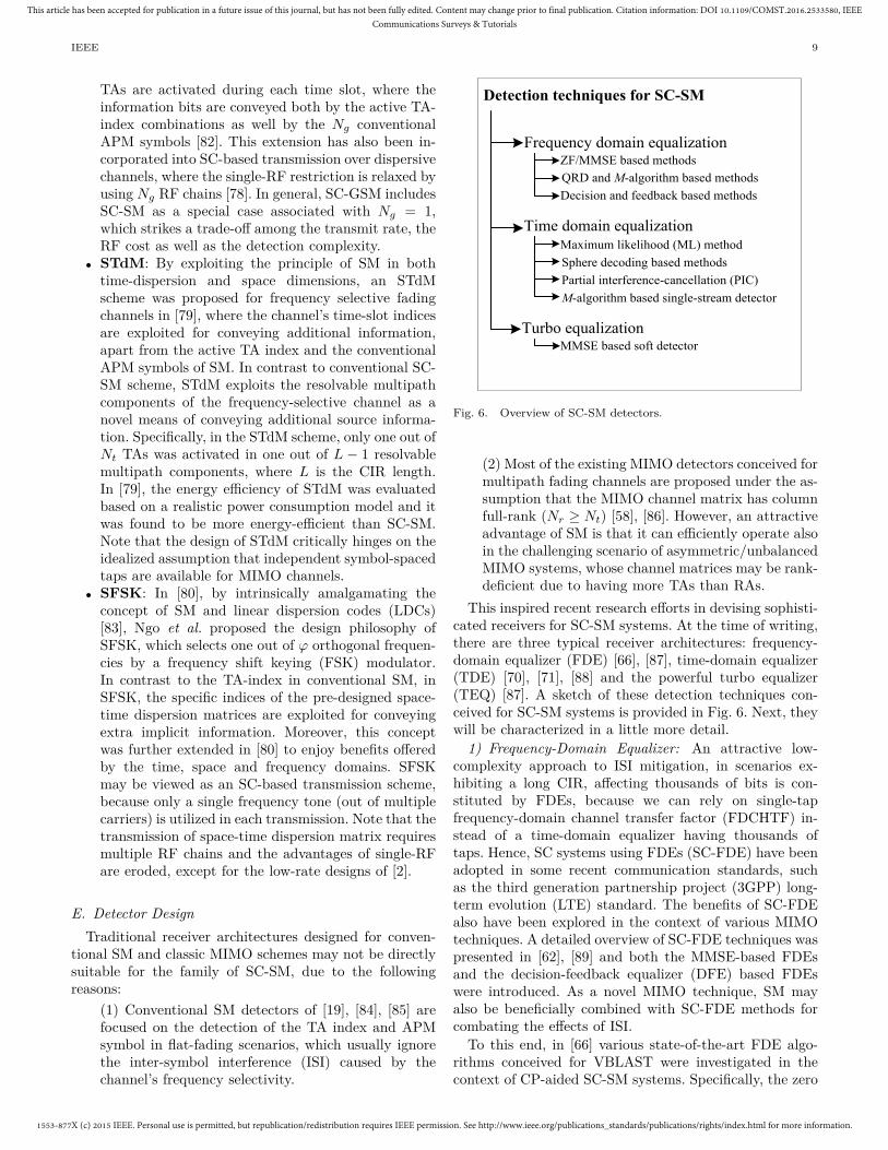
This inspired recent research efforts in devising sophisti-cated receivers for SC-SM systems. At the time of writing,there are three typical receiver architectures: frequency-domain equalizer (FDE) [66], [87], time-domain equalizer(TDE) [70], [71], [88] and the powerful turbo equalizer(TEQ) [87]. A sketch of these detection techniques con-ceived for SC-SM systems is provided in Fig. 6. Next, theywill be characterized in a little more detail.
1) Frequency-Domain Equalizer: An attractive low-complexity approach to ISI mitigation, in scenarios ex-hibiting a long CIR, affecting thousands of bits is con-stituted by FDEs, because we can rely on single-tapfrequency-domain channel transfer factor (FDCHTF) in-stead of a time-domain equalizer having thousands oftaps. Hence, SC systems using FDEs (SC-FDE) have beenadopted in some recent communication standards, suchas the third generation partnership project (3GPP) long-term evolution (LTE) standard. The benefits of SC-FDEalso have been explored in the context of various MIMOtechniques. A detailed overview of SC-FDE techniques waspresented in [62], [89] and both the MMSE-based FDEsand the decision-feedback equalizer (DFE) based FDEswere introduced. As a novel MIMO technique, SM mayalso be beneficially combined with SC-FDE methods forcombating the effects of ISI.
To this end, in [66] various state-of-the-art FDE algo-rithms conceived for VBLAST were investigated in thecontext of CP-aided SC-SM systems. Specifically, the zero
1553-877X (c) 2015 IEEE. Personal use is permitted, but republication/redistribution requires IEEE permission. See http://www.ieee.org/publications_standards/publications/rights/index.html for more information.
This article has been accepted for publication in a future issue of this journal, but has not been fully edited. Content may change prior to final publication. Citation information: DOI 10.1109/COMST.2016.2533580, IEEECommunications Surveys & Tutorials
IEEE 10
forcing (ZF)-based FDE of [90], the MMSE-based FDE(MMSE-FDE) of [91], and the decision feedback basedapproaches [62] as well as the QR decomposition combinedwith the M -algorithm (QRD-M) [62] were utilized torecover the transmit vector, in which an SM signal vectorwas viewed as a special type of the VBLAST signal.Then, the low-complexity matched filter (MF) based de-tection method of [16] was utilized, where the activatedTA index and the modulated APM constellation pointare separately estimated. That detector directly combinesthe classic VBLAST detector conceived for ISI channelsand the MF-based detector of conventional SM schemesfor demodulation. It was shown in [66] that the QRD-M detector outperforms other detectors in the contextof SC-SM systems, since it was designed based on thenear-optimal tree search principle by selecting only Mmost possible survived branches [92]. Moreover, in [87]the authors exploited the MMSE criterion to derive theweights of the FDE for the CP-aided SC-SM. Similar tothe classic MMSE-FDE, the received signals were firstconverted to their frequency-domain versions and thenMMSE-based linear filtering was invoked for estimatingthe frequency-domain SC-SM signals by minimizing theaverage minimum square error between the frequency-domain signals and the estimates. Then, these estimateswere converted to their time-domain counterparts, whichwere further divided into several independent SM symbols.Finally, the single-stream symbol-based ML detector of[84] was employed to each SM symbol for jointly detectingboth the active TA index as well as the transmitted APMsymbol. In contrast to the classic equalizers designed fortraditional MIMO systems, it was found in [87] that theirMMSE-based FDE taps depend on the sparsity of the SMsymbols. In short, this detector first employs a carefullydesigned MMSE-FDE for generating an initial estimateand then invokes the conventional single-stream ML de-tector of SM for symbol-by-symbol detection. As shownin [87], the complexity of this detector is independent ofthe CIR length. However, most of the above-mentionedFDE algorithms are only suitable for scenarios, where thechannel matrix is of full-rank, i.e. Nr ≥ Nt.
2) Time-Domain Equalizer: A well-known classic ap-proach to ISI-mitigation in the SC-based systems is basedon the employment of a TDE. Various TDE methods[62], such as the ML-based TDE, the low-complexitylinear TDE, the parallel interference cancellation (PIC),as well as the successive interference cancellation (SIC)have been extensively studied in the context of MIMOsystems. In contrast to the transmitted signals generatedby conventional MIMO schemes, the transmit vectors ofSM schemes are sparsely populated, since typically only asingle TA is activated [18], [19]. This constraint makes SMrather different from the classic STBC or the VBLASTschemes [1] and the TDE of SC-SM has to be carefullydesigned for exploiting the benefits of both SC and SMtechniques.
In [70], an optimal ML detector was proposed for SC-SMschemes, which carries out an exhaustive search for finding
the global optimum in the entire transmit signal space.This detector jointly detects the entire transmission frameto retrieve the original mr bits. The advantages of theML detector over the ZF and the MMSE detectors wereevaluated for the CP-aided SC-SM schemes. However, asboth the transmission rate and K increase, the complexityof the ML detector becomes excessive.
To attain a high diversity gain, in [71] a ZP-aidedSC-SM scheme was investigated. To reduce its detectioncomplexity, the authors viewed this system as a new kindof STBC scheme, which allows the use of STBC’s general-ized distribution law (GDL) to simplify the correspondingML detector. It was found that the order of the MLdetection complexity in the ZP-aided SC-SM scheme onlydepends on the CIR length rather than on the frame lengthK, as mentioned in Section II-B. To further reduce thecomplexity imposed by a large value of L, a low-complexityPIC-based receiver with SIC (PIC-R-SIC) was proposedin [71], which is capable of achieving both multipath- andreceiver- diversity gains (compared to ML detector) forsome specific channel conditions. Compared to the conven-tional PIC-R-SIC designed for STBC schemes operating ina flat-fading scenario, the extended PIC-R-SIC detectoris suitable for a dispersive channel, which operates byconverting the dispersive multipath channel into a set offrequency-flat block fading subchannels.
Another promising method of reducing the complexityof the ML detector is constituted by the sphere decod-ing (SD) algorithms of [93], the concept of which is tosearch for the closest lattice points within a certain SNR-dependent search radius. However, the number of surviv-ing search paths is still relatively high for a large tree andit may only be suitable for SC-SM schemes having a smallframe length K.
Relying on the concept of the classic M -algorithm, in[88] the authors proposed a low-complexity single-stream(LSS) detector for avoiding the channel inversion opera-tion of the PIC-R-SIC scheme, while striking a flexibletrade-off between the computational complexity imposedand the attainable BER. Note that in the traditionalM -algorithm, the QR-decomposition requires the channelmatrix to be a full-rank (column-wise) matrix. Hence,it can not be directly applied by the ZP-aided SC-SM,where the channel matrix may be rank deficient. In theproposed LSS, the QR-decomposition is avoided by prop-erly exploiting the single-stream ML detection of [84].It was found that their proposed LSS detector is alsocapable of efficient operation in the challenging rank-deficient channel scenarios.
3) Turbo Equalizer: It is worth noting that nearlyall wireless communication systems employ some formsof forward error correction (FEC) to counteract unpre-dictable transmission errors, which require soft-decisionbased detectors rather than the hard-decision based TDEand FDE. The classic TEQ [94] has also been demonstrat-ed to be an effective soft-decision receiver in frequencyselective fading channels, incorporating both equalizationand channel decoding. The basic concept of TEQ relies
1553-877X (c) 2015 IEEE. Personal use is permitted, but republication/redistribution requires IEEE permission. See http://www.ieee.org/publications_standards/publications/rights/index.html for more information.
This article has been accepted for publication in a future issue of this journal, but has not been fully edited. Content may change prior to final publication. Citation information: DOI 10.1109/COMST.2016.2533580, IEEECommunications Surveys & Tutorials
IEEE 11
SNR [dB]
0 5 10 15 20 0 5 10 15 20
SNR [dB]
10-5
10-4
10-3
10-2
10-1
100
BE
R
(a) Nr=1 (b) Nr=2
SC-SM, ML
SM-OFDM, ML
SC-SM, PIC-R-SIC
SC-SM, LSS, M=4
SC-SM, LSS, M=8
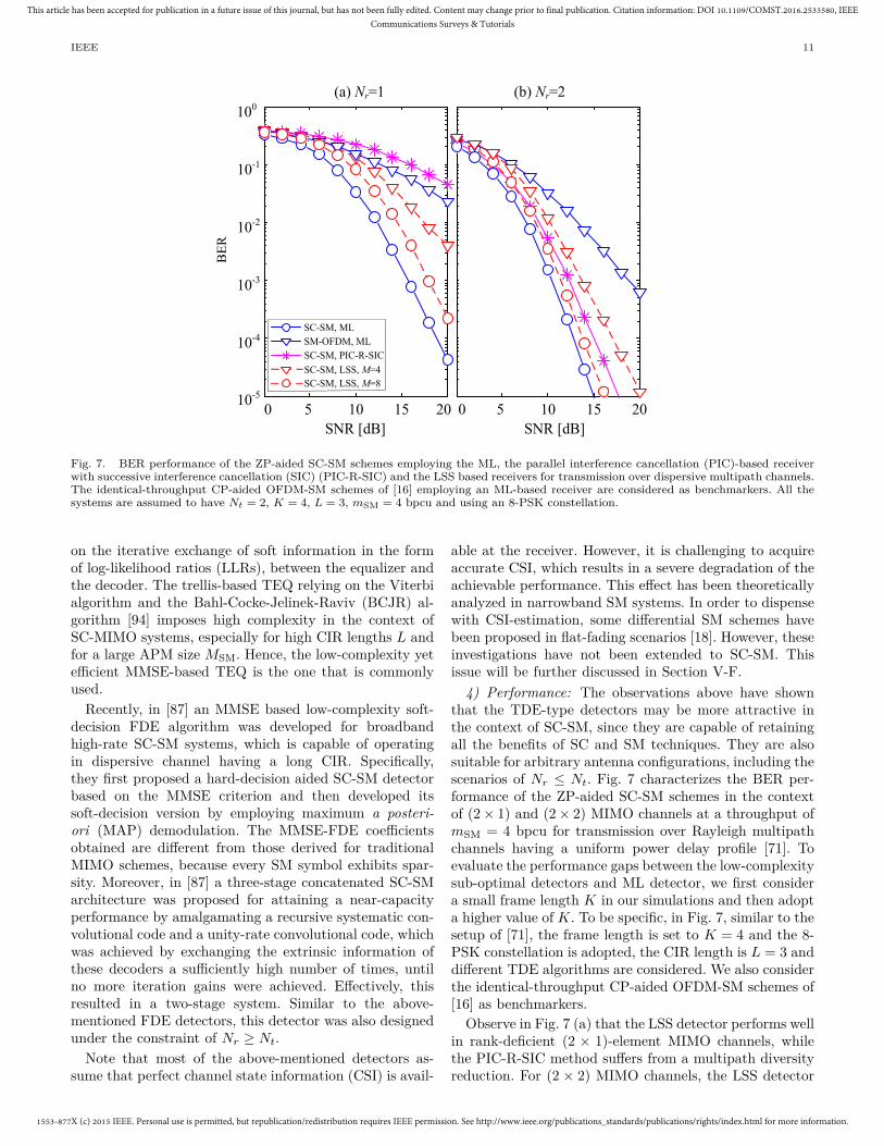
Fig. 7. BER performance of the ZP-aided SC-SM schemes employing the ML, the parallel interference cancellation (PIC)-based receiverwith successive interference cancellation (SIC) (PIC-R-SIC) and the LSS based receivers for transmission over dispersive multipath channels.The identical-throughput CP-aided OFDM-SM schemes of [16] employing an ML-based receiver are considered as benchmarkers. All thesystems are assumed to have Nt = 2, K = 4, L = 3, mSM = 4 bpcu and using an 8-PSK constellation.
on the iterative exchange of soft information in the formof log-likelihood ratios (LLRs), between the equalizer andthe decoder. The trellis-based TEQ relying on the Viterbialgorithm and the Bahl-Cocke-Jelinek-Raviv (BCJR) al-gorithm [94] imposes high complexity in the context ofSC-MIMO systems, especially for high CIR lengths L andfor a large APM size MSM. Hence, the low-complexity yetefficient MMSE-based TEQ is the one that is commonlyused.
Recently, in [87] an MMSE based low-complexity soft-decision FDE algorithm was developed for broadbandhigh-rate SC-SM systems, which is capable of operatingin dispersive channel having a long CIR. Specifically,they first proposed a hard-decision aided SC-SM detectorbased on the MMSE criterion and then developed itssoft-decision version by employing maximum a posteri-ori (MAP) demodulation. The MMSE-FDE coefficientsobtained are different from those derived for traditionalMIMO schemes, because every SM symbol exhibits spar-sity. Moreover, in [87] a three-stage concatenated SC-SMarchitecture was proposed for attaining a near-capacityperformance by amalgamating a recursive systematic con-volutional code and a unity-rate convolutional code, whichwas achieved by exchanging the extrinsic information ofthese decoders a sufficiently high number of times, untilno more iteration gains were achieved. Effectively, thisresulted in a two-stage system. Similar to the above-mentioned FDE detectors, this detector was also designedunder the constraint of Nr ≥ Nt.
Note that most of the above-mentioned detectors as-sume that perfect channel state information (CSI) is avail-
able at the receiver. However, it is challenging to acquireaccurate CSI, which results in a severe degradation of theachievable performance. This effect has been theoreticallyanalyzed in narrowband SM systems. In order to dispensewith CSI-estimation, some differential SM schemes havebeen proposed in flat-fading scenarios [18]. However, theseinvestigations have not been extended to SC-SM. Thisissue will be further discussed in Section V-F.
4) Performance: The observations above have shownthat the TDE-type detectors may be more attractive inthe context of SC-SM, since they are capable of retainingall the benefits of SC and SM techniques. They are alsosuitable for arbitrary antenna configurations, including thescenarios of Nr ≤ Nt. Fig. 7 characterizes the BER per-formance of the ZP-aided SC-SM schemes in the contextof (2 × 1) and (2 × 2) MIMO channels at a throughput ofmSM = 4 bpcu for transmission over Rayleigh multipathchannels having a uniform power delay profile [71]. Toevaluate the performance gaps between the low-complexitysub-optimal detectors and ML detector, we first considera small frame length K in our simulations and then adopta higher value of K. To be specific, in Fig. 7, similar to thesetup of [71], the frame length is set to K = 4 and the 8-PSK constellation is adopted, the CIR length is L = 3 anddifferent TDE algorithms are considered. We also considerthe identical-throughput CP-aided OFDM-SM schemes of[16] as benchmarkers.
Observe in Fig. 7 (a) that the LSS detector performs wellin rank-deficient (2 × 1)-element MIMO channels, whilethe PIC-R-SIC method suffers from a multipath diversityreduction. For (2 × 2) MIMO channels, the LSS detector

1553-877X (c) 2015 IEEE. Personal use is permitted, but republication/redistribution requires IEEE permission. See http://www.ieee.org/publications_standards/publications/rights/index.html for more information.
This article has been accepted for publication in a future issue of this journal, but has not been fully edited. Content may change prior to final publication. Citation information: DOI 10.1109/COMST.2016.2533580, IEEECommunications Surveys & Tutorials
IEEE 12
TABLE IIIComplexity orders of different time-domain detectors for ZP-aided SC-SM scheme.
Detector Complexity Order (Flops)ML O((NtMSM)L)PIC-R-SIC O(N2
t K2Nr) + O(K3Nt) + O((K + L)N2t MSMK)
LSS O(N2t MSMMK) + O(LKNtNrM)
TABLE IVComplexity of different detectors for ZP-aided SC-SM
scheme in terms of the number of real-valuedmultiplications, where the setup is the same as that in Fig.
7.Nt = 2, K = 4, L = 3, 8-PSK
Detector ML PIC-R-SIC LSSM = 4 M = 8
Nr=1 1.3×10⁷ 1.0×10⁴ 5.4×10³ 1.1×10⁴
Nr=2 2.7×10⁷ 2.5×10⁴ 1.1×10⁴ 2.1×10⁴
TABLE VComplexity of the PIC-R-SIC and LSS detectors for
ZP-aided SC-SM scheme, where the setup is the same as thatin Fig. 8.
Nt = 32, K = 128, L = 6, QPSK
Detector PIC-R-SIC
LSSM = 4 M = 8
Nr=2 5.9×10¹² 1.4×10⁹ 2.2×10⁹
Nr=4 7.6×10¹² 2.2×10⁹ 4.3×10⁹
having M = 8 outperforms the PIC-R-SIC method andprovides a signal-to-noise ratio (SNR) gain of about 1.6dB at the BER of 10−5. Moreover, in Fig. 7(b) the perfor-mance gap between the LSS detector and the exhaustive-search-based ML detector is only about 5 dB and 1 dBfor M = 4 and M = 8, respectively. This gap can befurther reduced by setting a larger value of M at the costof a higher complexity. In general, the LSS detector iscapable of adjusting the parameter M for striking a flexibletradeoff between the attainable BER and the detectioncomplexity imposed.
The above-mentioned benefits of the LSS detectorrecorded for the ZP-aided SC-SM are also visible in Fig. 8,where a long frame length of K = 128 and a large numberof TAs, namely Nt = 32 are considered in the extendedvehicular a channel (EVA) model [90]. In Fig. 8, the BERperformance of the optimal ML detector is not provideddue to its excessive complexity. It is shown in Fig. 8 thatthe BER of the PIC-R-SIC scheme may have an error flooreffect under rank-deficient channel conditions, which wasalso observed in [88].
5) Complexity: In Table III, the complexity orders ofthe PIC-R-SIC, the ML and the LSS detectors employedin Figs. 7 and 8 are compared. It is shown that thecomplexity of the ML detector is unaffordable as it growsexponentially with the CIR length L. Based on the resultsof Tables II and III, it is noted that the time-domainbased LSS detector has a similar complexity order to thatof the classic linear MMSE based detector. In Tables IVand V, we also provide the approximate complexity of theconfigurations adopted in Figs. 7 and 8. It is shown thatthe LSS detector is capable of striking a flexible tradeoffin terms of the BER attained and the complexity imposed
0 2 4 6 8 10 12 14 16
Nt=32, K=128,
EVA channels,QPSK
SNR [dB]
10-3
10-2
10-1
100
BE
R
Nr=4
Nr=2
SC-SM, PIC-R-SIC, Nr=4
SC-SM, LSS, M=4
SC-SM, LSS, M=8
SC-SM, PIC-R-SIC, Nr=2
Fig. 8. BER performance of the ZP-aided SC-SM schemes employingthe PIC-R-SIC and the LSS based methods for transmission overthe EVA channels, having L = 6, QPSK modulation and Nr = 2, 4.Here, the performance of these detectors with a higher number ofTAs Nt = 32 and a longer frame length K = 128 are investigated,compared to Fig. 7.
by adjusting the parameter M .
III. Potential Advantages and DisadvantagesIn light of the transceiver design described in Section
II, we summarize some potential advantages, tradeoffs anddisadvantages of SC-SM in Fig. 9.
A. Potential Advantages1) Simple Transmitter Design: In conventional MI-
MO systems, such as the VBLAST and the STBCschemes, the hardware complexity and cost rise with thenumber of TAs Nt. Moreover, the deleterious effects of RFcircuit mismatches and coupling impairments also growwith the value of Nt. These factors limit the number ofantennas. As shown in Fig. 2, SC-SM relies on the uniqueencoding philosophy of activating one out of numerousTAs at each time slot, hence only a single RF chain ( Ng
RF chains for the SC-GSM scheme, Ng < Nt) is requiredinstead of Nt parallel RF chains. Hence its RF sectionhas a reduced complexity and cost. On the other hand,in conventional OFDM-based MIMO transmissions, thecomplexity imposed by performing the DFT operationsfor its signal modulation and demodulation also increases

1553-877X (c) 2015 IEEE. Personal use is permitted, but republication/redistribution requires IEEE permission. See http://www.ieee.org/publications_standards/publications/rights/index.html for more information.
This article has been accepted for publication in a future issue of this journal, but has not been fully edited. Content may change prior to final publication. Citation information: DOI 10.1109/COMST.2016.2533580, IEEECommunications Surveys & Tutorials
IEEE 13
Potential Advantages and
Disadvantages of SC-SM
Some Tradeoffs
and
Disadvantages
Potential
Advantages
Throughput, Diversity,
Detection Complexity
and RF Cost Tradeoff
Overhead of
Channel
Estimation
Antenna
Array
Design
Simple
Transmitter
Design
Low
PAPR
High
Throughput
Flexible
Design
Simple
Receiver
Design
Robustness
to Phase
Noise
High
Energy
Efficiency
Fig. 9. A summary of main advantages and disadvantages of the SC-SM scheme.
with Nt. As shown in Section II and Fig. 2, this compu-tational complexity and the RF hardware complexity canbe reduced by employing the SC-SM based transmitteradvocated.
2) Simple Receiver Design: Data detection in theconventional MIMO systems is one of the most challeng-ing tasks in terms of both its computational complexityand its power consumption, especially in the LS-MIMOscenarios. In dispersive channels, the employment of SCor OFDM techniques further increases the dimensionalityof the underlying detection problem. In SM, since onlya single TA is activated for transmission, this allows usto design a low-complexity single-stream receiver, such asthe LSS detector. Moreover, based on the unique bit-to-vector mapping rule of SC-SM detailed in Algorithm 1,the transmit vector of SC-SM associated with each TA hasas low a fraction of nonzero elements as K/Nt for each rowof X. Usually, a matrix or vector is referred to as sparse,if the number of nonzero elements in it is less than 20%of the total number of elements. Since the sparsity ratioof SC-SM is 1/Nt, for Nt > 4 the transmit matrix X isdeemed sparse and hence the detection can be regardedas a sparse reconstruction problem. Therefore, the classicsparse reconstruction theory [95], [96] may be invoked forrecovering the transmitted signals.
Accordingly, a number of related contributions haveconcentrated on the design of SM detection schemes basedon compressive sensing (CS). A message passing detectionalgorithm was proposed in [105] for the multiple accesschannel (MAC) in conjunction with a high number ofantennas at the BS. An iterative detector was developedfor large-scale MACs in [106], where the authors decou-pled the antenna and symbol estimation processes forreducing the total detection complexity. The algorithmintroduced in [112] beneficially exploits the sparsity ofSM transmission in the MAC. In [107], a generalizedapproximate message passing detector was preferred tothe high-complexity stage-wise linear detector. A closelyrelated approach has also been developed in [113] in orderto mitigate the effects of spatial correlation imposed ontightly-packed antennas.
3) Low PAPR and Robustness to Phase Noise:OFDM has attracted substantial interests because it offersa powerful and practical means to mitigate the effects ofISI in high-throughput MIMO transmissions [58]. Howev-er, the DFT operation based modulation at the transmit-ter disperses each sub-carrier’s modulated signal across theentire DFT-block and hence erodes the single-RF benefitsof SM-MIMO [87], whilst simultaneously resulting in ahigh PAPR. By contrast, SC-SM is capable of retaining allthe benefits of SM, whilst exhibiting a lower PAPR thanits OFDM-based counterpart [66], [71], [87]. As a result,the performance of SM is less affected by the transmitter’spower amplifier nonlinearities. A further benefit of SC-SMis its higher robustness both to the frequency offset andto the phase noise, than that of the OFDM scheme, owingto its inherent SC structure.
As an example, we assume that the number of TA isNt = 2, the throughput is mSM = 5 bpcu. The datablock size is K = 256 and the oversampling factor is set toβ = 4 for PAPR calculation as pulse shaping is considered.In Fig. 10, we present the transmit signal generationand PAPR calculation process of SC-SM and OFDM-SMschemes. The detailed signal generation processes of SC-SM and OFDM-SM are similar to that in Fig. 4, exceptthat a pulse shaping unit is added in SC-SM scheme forpractical signal transmission.
Based on the transmit signal model of Fig. 10, the cor-responding complementary cumulative distribution func-tions (CCDFs) of the PAPR of both SC-SM and OFDM-SM systems are shown in Fig. 11. For the sake of simplicity,we only give the CCDF result of the PAPR for thesignal vector transmitted over TA 1, since the CCDFresult recorded at TA 2 is similar to that of TA 1. TheCCDF explicitly shows the probability of having a PAPR,which is higher than a certain PAPR threshold of PAPR0,namely that we have Pr{PAPR > PAPR0}. To evaluatethe effects of pulse shaping on SC-SM, we convolve eachtransmitted symbol waveform with a raised-cosine filterhaving the roll-off factor α.
As observed in Fig. 11, in the absence of pulse shaping,the PAPR of the SC-SM scheme is about 8.5 dB lower

1553-877X (c) 2015 IEEE. Personal use is permitted, but republication/redistribution requires IEEE permission. See http://www.ieee.org/publications_standards/publications/rights/index.html for more information.
This article has been accepted for publication in a future issue of this journal, but has not been fully edited. Content may change prior to final publication. Citation information: DOI 10.1109/COMST.2016.2533580, IEEECommunications Surveys & Tutorials
IEEE 14
Input bits
16-QAM
Active
antenna
SM Add ZPb
1b
2b
S/P
111001010101001001
101001010…time
PAPR: SC-SM
Input
bits
16-
QAM
Active
antenna
SMb
1b
2b
S/P
PAPR: OFDM-SM
frequency
Add
CP
K-point
IFFT
111001010101001001
101001010…
Length of b is
5K=1280
K=256 symbols
Frequency-domain
vector for TA1
K=256 symbols
signal vector for TA1
signal vector for TA2
Length of b is
5K=1280
time
K=256 symbols
Frequency-domain
vector for TA2
Time-domain vector
for TA1
Time-domain vector
for TA2
Pulse
shaping
Oversampling factor is 4
Calculate PAPR
value in TA1
Calculate PAPR
value in TA1
OF
DM
-SM
sig
nal
po
wer
Peak power
Average power
OFDM symbol duration
SC
-SM
sig
nal
pow
er
SC symbol duration
Peak power
Average power
Fig. 10. The example of PAPR calculations for SC-SM and OFDM-SM schemes with Nt = 2, mSM = 5 bits/channel-use. We use 4 timesoversampling to calculate PAPR for each block when pulse shaping is considered.
0 2 4 6 8 10 12 14
PAPR0 [dB]
10-4
10-3
10-2
10-1
100
CC
DF
(P
r[P
AP
R>
PA
PR
0]) SC-SM without
pulse shaping
SC-SM with pulse
shaping
0.6,0.8 !
OFDM-SM
Fig. 11. Comparison of CCDF of PAPR for the SC-SM and the OFDM-SM systems having Nt = 2, K = 256, mSM = 5 bpcu and operatingwith 16-QAM constellation. For the SC-SM with pulse shaping in the classic signal domain, the roll-off factor of the raised-cosine pulse filteris α = 0.6 and 0.8.
than that of the SC-OFDM scheme at a CCDF of 10−3.As a further metric, the PAPR of the transmitted SC-SMsignals only has a 1% probability of being above 3.5 dB.Fig. 11 also shows that in conjunction with the raised-cosine filter, the PAPR increases for the SC-SM schemes,but it still remains better than that of OFDM-SM. It isobserved in Fig. 11 that the performance can be improvedby using a larger value of the roll-off factor α at the cost ofan increased out-of-band radiation [82]. This implies thatthere is a tradeoff between the attainable PAPR and the
out-of-band radiation imposed.
In Fig. 11, the effects of antenna switching in SM arenot considered in the design of the pulse shaping filter. Asshown in [117], a high roll-off factor is necessary for con-ventional raised-cosine filter to ensure that the transmitpower is concentrated within a short time period so as toenable a single RF chain in SM. Hence, two large values ofα are utilized in the PAPR comparison of Fig. 11, such asα = 0.6 and 0.8. The design of time-limited waveforms forsingle-RF based SC-SM scheme is still a challenge, which

1553-877X (c) 2015 IEEE. Personal use is permitted, but republication/redistribution requires IEEE permission. See http://www.ieee.org/publications_standards/publications/rights/index.html for more information.
This article has been accepted for publication in a future issue of this journal, but has not been fully edited. Content may change prior to final publication. Citation information: DOI 10.1109/COMST.2016.2533580, IEEECommunications Surveys & Tutorials
IEEE 15
will be further discussed in Section V-A.4) High Throughput and High Energy Efficien-
cy: As a new three-dimensional (3-D) hybrid modulationscheme, SM exploits the indices of the TAs as an additionaldimension invoked for transmitting information, apartfrom the classic two-dimensional (2-D) APM [82]. SC-SM also adopts this principle and hence achieves a higherthroughput than that of the single-antenna and the STBC-MIMO systems. In dispersive channels this gain can befurther exploited by using the STdM-like schemes of [79],which relies on the index of the resolvable multipath linksas a means of conveying additional source information.Since SM can be realized by using a single RF front-end, the high-cost power amplifier, which is typicallyresponsible for the vast majority of power dissipation atthe transmitter, can be reduced. Specifically, recent resultsbased on a realistic power consumption model have shownthat a SM-aided base station (BS) has a considerablepower consumption gain compared to the multi-RF chainassisted MIMO arrangements (up to 67% more energyefficient in the context of Nt = 4) [97]. This energy benefitmay also be retained by the SC-SM systems.
5) Flexible Design: As shown in Fig. 2, due to thesingle-TA transmission mode, the minimum number ofRAs required for efficient detection can be set to one,regardless of how many TA there are. Hence, SC-SM canbe flexibly configured for diverse TA and RA configura-tions, especially for the challenging scenario of asymmet-ric/unbalanced MIMO systems. As a further advance, SC-SM can be jointly designed in combination with the classicVBLAST and the STBC schemes for striking a flexibletradeoff among the attainable transmit rate, the diversitygain and the cost, which retains the key advantages ofSM, while activating multiple TAs [75], [98]. Furthermore,SC-SM can be employed for exploiting the potential mul-tipath diversity or the resolvable multipath-component-based multiplexing gain available in dispersive channels,i.e., the ZP-aided SC-SM scheme of [71] and the STdMscheme of [79]. Additionally, in SC-SM, the prefix vectorcan be flexibly selected according to the practical systemrequirements.
B. Some Tradeoffs and Disadvantages1) Throughput, Diversity, Detection Complexity and
RF Cost Tradeoff: In contrast to V-BLAST which iscapable of achieving a high multiplexing gain, the familyof SC-SM schemes may offer only a logarithmic (ratherthan a linear) increase of the throughput with the numberof TA Nt or the number of TA combinations. This maylimit SC-SM for achieving very high spectral efficiencies.Moreover, the conventional SC-SM schemes only achievereceiver diversity and multipath diversity, but no transmitdiversity. In conventional narrowband SM scheme, thisimpediment can be circumvented by employing open-loopas well as closed-loop transmit symbol design techniques[16]. However, these techniques may be not directly suit-able for SC-SM systems. Indeed, the degree of freedom
in a MIMO system can be allocated by different waysto achieve different tradeoff among different conflictingperformance factors. As a new MIMO scheme, SC-SMexploits this degree of freedom to reduce the numberof transmit RF chains and the detection complexity, atcertain losses of diversity and multiplexing gains.
2) Overhead of Channel Estimation: The coherent de-tection of the SC-SM scheme in Fig. 2 requires that CSIis available at the receiver. However, it is challenging toacquire accurate CSI of all MIMO channels. The peculiartransmit encoding of SC-SM based over a limited numberof RF chains may introduce an additional training over-head, since the CSI of the MIMO subchannels may not beestimated simultaneously.
3) Antenna Array Design: Compared to the convention-al full-RF based MIMO schemes, the configuration anddeployment of the TA arrays for the single-RF based SC-SM pose some design challenges, because it requires fastTA switching and low spatial correlation between TAs.Due to the unique encoding principle of SC-SM, the activeTA index used to convey information may be changedsymbol-by-symbol, hence a high-speed RF switching isrequired. Moreover, SC-SM requires sufficiently low cor-relation among the channels of the spatial streams foryielding adequate BER performance. Hence, the channelcorrelation and mutual coupling effects should be carefullyconsidered in the TA array design and implementation forSC-SM based systems.
These above-mentioned advantages and disadvantagesindicate that the SC-SM scheme appears to be an at-tractive low-complexity low-cost option for the emergingfamily of LS-MIMO systems. Recently, many promisingpreliminary solutions have been developed to circumventthe above-mentioned disadvantages, which succeeded inimproving the tradeoff among the conflicting factor as-sociated with the design of SC-SM systems, such as thecomputational complexity imposed, the attainable BER,the achievable throughput, the RF cost and the pilotoverhead, just to name a few. For example, the SC-GSMscheme may be invoked for improving the throughput, andthe STBC scheme can be amalgamated with SC-SM forthe sake of increasing the transmit diversity order, whiledifferential SC-SM schemes can be developed for reducingor eliminating the pilot overhead. More related discussionswill be provided in Section V. In the next Section, we willprovide an up-to-date review of the application of SC-SMin LS-MIMO scenarios.
IV. SC-SM for Multiuser LS-MIMO SystemsThe observations and advantages described above have
recently sparked off a flurry of research activities aimedat understanding the system design, the signal processingand the detector concepts of SC-SM for conceived mul-tiuser (MU) LS-MIMO systems, as shown in Table VI.In this section, we first review and discuss the SC-basedtransmission research in the context of LS-MIMO designand then focus our attention on the recent SC-SM schemesproposed for the LS-MIMO transmissions.

1553-877X (c) 2015 IEEE. Personal use is permitted, but republication/redistribution requires IEEE permission. See http://www.ieee.org/publications_standards/publications/rights/index.html for more information.
This article has been accepted for publication in a future issue of this journal, but has not been fully edited. Content may change prior to final publication. Citation information: DOI 10.1109/COMST.2016.2533580, IEEECommunications Surveys & Tutorials
IEEE 16
TABLE VIMajor Contributions on SC-SM and Its Large-Scale MIMO Developments.
Year Author(s) Contribution2008 Mesleh et al. [16] The general bits-to-symbol mapping model of SM was proposed.2011 Ngo et al. [80] The philosophy of SFSK was proposed, which is a frequency-domain extension of SM
for dispersive channels.Zhou et al. [66] The concept of SC-SM was proposed for dispersive channels and various linear and
nonlinear FDE methods were investigated.2012 Som and Chockalingam [70] A diversity analysis framework was proposed for the CP-aided SC-SM.2013 Rajashekar et al. [71] A ZP-aided SC-SM system was proposed, which is capable of offering full multipath
diversity by employing a low-complexity PIC-R-SIC detector.2014 Narayanan et al. [100] A single-cell downlink broadcast MU SM framework was investigated.
Humadi et al. [101] A new SM-based transmitter was proposed for large-scale MU downlink transmissionsystems, where can be viewed an extension of the RSM scheme for MU transmissions.
Narasimhan et al. [105] The superiority of the large-scale SC-SM over the conventional LS-MIMO wasinvestigated and two low-complexity MU detectors were proposed for uplink transmissions.
Wang et al. [112] The sparsity and the prior probability distribution of the transmit signal were exploitedin the detector design of large-scale CP-aided SC-SM uplink transmission systems.
Sugiura and Hanzo [87] An MMSE based low-complexity soft-decision FDE algorithm was proposedfor the broadband CP-aided SC-SM systems.
2015 Narasimhan et al. [78] A generalized SC-SM, termed as SC-GSM, was proposed for the LS-MIMO uplinktransmission systems, which is capable of striking a trade-off among the transmit rate,the RF cost and the detection complexity.
Zheng et al. [79] An STdM scheme was proposed for frequency selective fading channels, where the channeltime-slot index was employed for conveying additional information.
Xiao et al. [88] An attractive LSS detector was proposed for the ZP-aided SC-SM, which can efficientlywork in the rank-deficient LS-MIMO channels.
Wang et al. [113] The effects of the low-resolution analog-to-digital convertors (ADCs) were investigated inlarge-scale CP-aided SC-SM uplink transmissions.
A. SC-based Transmission for LS-MIMO SystemsAgain, in the design of LS-MIMO systems, most of
the existing contributions rely on the assumption of flatfading channels. One of the reasons for this assumptionis that there is some evidence that ISI can be treated asadditional thermal noise [10], [65]. However, this assump-tion has a limited applicability for practical transmissionsover dispersive channels, when only a limited number ofTAs is available. For the sake of combating the effectsof ISI introduced by propagation over frequency-selectivefading channels, OFDM is an attractive technique, since itfacilities single-tap based equalization. However, it suffersfrom a high PAPR, as shown in Section III.
For these reasons, various LS-MIMO designs have beeninvestigated in the context of energy-efficient SC or SC-like schemes [12], [63]–[65]. More specifically, in [13], anew soft-output data detector was proposed for uplinktransmission by employing SC frequency division multipleaccess (SC-FDMA)-based LS-MIMO systems. In [13] somepractical implementations were conceived for the scenariowhere all users are equipped with a single antenna. Specif-ically, the complexity issues of data detection were ad-dressed and a low-complexity soft MMSE-based detectorwas proposed in [13]. In particular, the inherent matrixinversion of the MMSE algorithm was approximated by alow-complexity Neumann series expansion. It was shownthat their proposed method imposes a complexity order of
O(U2), which is lower than the complexity order of O(U3)imposed by the conventional MMSE-based detector, whereU is the number of users. However, this approximatemethod may result in a degradation of BER performance.
In [63] the authors proposed a novel SC-based LS-MIMO scheme for frequency-selective multiuser Gaussianbroadcast channels, where efficient downlink precodingwas invoked. This transmit precoder (TPC) design isbased on the assumption that the number of TAs Ntot
at the BS is substantially higher than the number ofusers U (Ntot >> U). Hence the channel hardeningeffect can be exploited to design the TPC matrix andthe resultant TPC matrix is the linear weighted channelmatrix (matched filter), instead of the inversion of thechannel matrix. The extent of channel hardening can beviewed a measure of channel orthogonality, as discussed in[7]–[12]. It was shown [63] that the proposed SC schemeachieved a near-optimal sum-rate, with the aid of a low-complexity equalization-free receiver.
More recently, in [64], the symbol-error rates (SERs)of the MF and MMSE detectors were investigated in thecontext of large-scale multiple-input single-output (MISO)systems both for a negative-exponentially decaying CIRmodel as well as for the typical urban channel model [99].It was found [64] that the MMSE based detector performsbetter than the MF receiver. In [65], the authors inves-tigated the ML equalization of the SC-based LS-MIMO

1553-877X (c) 2015 IEEE. Personal use is permitted, but republication/redistribution requires IEEE permission. See http://www.ieee.org/publications_standards/publications/rights/index.html for more information.
This article has been accepted for publication in a future issue of this journal, but has not been fully edited. Content may change prior to final publication. Citation information: DOI 10.1109/COMST.2016.2533580, IEEECommunications Surveys & Tutorials
IEEE 17
Spatial
Modulation
LS-MIMO
Base
Station
(Precoding)
User 1
User 2
User U
Information
User 1
User 2
User U
LS-MIMO
Base
Station
(MU
detection)
Spatial
ModulationInformation
Spatial
ModulationInformation
Spatial
ModulationInformation
(a) Downlink
(b) Uplink
Fig. 12. The design framework for large-scale SC-SM based MU transmission. (a) The general downlink system model. (b) The generaluplink system model.
uplink for transmission over a Rician fading channel, inorder to mitigate the ISI generated by the combination ofthe signals received from different antennas through a low-complexity MF. Moreover, by using this novel design, theMU-interference (MUI) caused by the line-of-sight (LOS)components, which may lead to an error-floor in the highSNR region for the conventional single-tap equalizer of[64], can be effectively mitigated.
Note that although the above-mentioned research showsthat the SC-based transmission constitutes a promisingdesign alterative for LS-MIMO transmissions, most of theexisting research has been based on the assumption thatNtot >> U is satisfied and that all users are equipped witha single antenna. The existing solutions may be furtherimproved in order to meet the demand for high-throughputtransmissions, in which all the users are equipped withmultiple antennas and the number of users U is large.In this case, future SC-based MIMO transmission tech-nique should be designed to satisfy a diverse range ofpractical requirements and to strike an attractive tradeoffamongst the RF cost, the detection complexity and theBER performance. As it will be shown in the followingtwo subsections, SC-SM can indeed be further developedfor designing LS-MIMO systems to achieve these benefitsboth in downlink and uplink transmissions.
B. SC-SM Large-Scale MIMO Designs for DownlinkTransmission
Owing to the compelling advantages of the SC-SMscheme discussed in Section III, recently it has beenproposed for the MU LS-MIMO downlink, where the base
station may be equipped with hundreds of TAs but only afew RF chains, while each user’s receiver can be equippedwith either a single or multiple antennas yet relying ona single RF chain. The general downlink model of themultiuser SM based LS-MIMO system is shown in Fig. 12(a). One of the key design challenges of this architectureis to construct a beneficial TPC for mitigating the MUI.
To this end, in [100] a single-cell downlink MU SMbroadcast framework was investigated, which has Ntot TAsat the base station and U active users, while each user isequipped with a single RA. In the proposed scheme, theNtot TAs are split into U subsets each associated with Nd
TAs and each subset is then allocated to a specific activeuser. These TA-subsets are then used for an SM-basedtransmission. Since there is a total of U TA subsets andonly a single TA is active in each subset, the number of RFchains required is equal to U . In [100], the SM-based datavector was preprocessed by using a carefully designed TPCfor mitigating the MUI, while simultaneously retainingthe benefits of SM. As shown in [100], the classic ZFand MMSE TPCs derived for conventional MU MIMOsystems are not suitable for SC-SM based MU downlinksystems. This is because SM enables data decoding byexploiting the differences among the CIRs of the transmit-to-receive wireless links, but these TPCs may eliminate thechannel matrix and hence jeopardize the bits carried bythe TA indices. The TPC designed in [100] has consideredthis effect, which is capable of eliminating of MUI andretaining the CIR differences. The resultant TPC dependson the MU channel matrix HMU and can be expressed as(HMU)−1diag(HMU), where diag(·) denotes the diagonal

1553-877X (c) 2015 IEEE. Personal use is permitted, but republication/redistribution requires IEEE permission. See http://www.ieee.org/publications_standards/publications/rights/index.html for more information.
This article has been accepted for publication in a future issue of this journal, but has not been fully edited. Content may change prior to final publication. Citation information: DOI 10.1109/COMST.2016.2533580, IEEECommunications Surveys & Tutorials
IEEE 18
TABLE VIIMajor Contributions on SC-SM and Its Large-Scale MIMO Developments.
Literature Prefix Transmission Channel Channel RF CSI Receiverscheme type coding model required estimation design
Narayanan N. A. MU downlink, N. A. Flat-fading User: 1 Perfect CSI Single-useret al. [100] SM-MIMO BS: U ML detectorHumadi N. A. MU downlink, N. A. Flat-fading User: 1, Perfect CSI ML detectoret al. [101] SM-MIMO Flat-fading BS:Ntot
Narasimhan N. A. MU uplink, N. A. Flat-fading User: 1, Perfect CSI MP and localet al. [105] SM-MIMO BS:Ntot search detectorsWang CP MU uplink, N. A. Frequency User: 1, Least square Low-complexityet al. [112] SM-MIMO selective BS:Ntot estimation generalized
channel MP detectorSugiura and CP Point-to-Point, Convolutional Frequency Transmitter: 1 Perfect CSI Soft MMSEHanzo [87] SM-MIMO code selective detector and
channel TEQNarasimhan CP MU uplink, N. A. Flat-fading User:1∼(Nu−1), Perfect CSI, Two low-et al. [78] GSM-MIMO and frequency BS:Ntot MMSE-based complexity MP
selective estimation detectorschannel
Zheng N. A. Point-to-Point, N. A. Frequency Transmitter: 1 Perfect CSI ML detectoret al. [79] SM-MIMO selective
channelXiao ZP Point-to-Point, N. A. Frequency Transmitter: Perfect CSI LSS detectoret al. [88] GSM-MIMO selective 1∼(Nt−1)
channelGarcia N. A. MU uplink N. A. Flat Fading User: 1, Perfect CSI, Low complexityet al. [107] SM-MIMO BS: Ntot MMSE estimation CS detectorWang CP MU uplink, N. A. Frequency User: 1, Least square Factor graphet al. [113] SM-MIMO selective BS:Ntot estimation and MP-based
channel detectorsYu N. A. Point-to-Point, N. A. Flat-fading Transmitter: Perfect CSI Low-complexityet al. [114] GSSK-MIMO 1∼(Nt−1) CS detectorLiu N. A. Point-to-Point, N. A. Flat-fading Transmitter: Perfect CSI Low-complexityet al. [115] GSM-MIMO 1∼(Nt−1) CS detectorPeng N. A. Point-to-Point, N. A. Flat-fading Transmitter: Perfect CSI Sparse K-bestet al. [116] GSSK-MIMO 1∼(Nt−1) detector
U : the number of users.Ntot: the number of antennas at BS for the MU transmission.Nu: the number of antennas at each user for the MU transmission.Nt: the number of antennas at transmitter for the point-to-point transmission.
matrix operator.The simulation results in [100] shows that their proposed
scheme is capable of providing the same BER perfor-mance as that of the single-user SM transmission, i.e.,interference-free. To avoid CSI estimation, an interference-aware detector was also proposed in [100]. Unlike theconventional MIMO-aided MU downlink systems, [100]shows that the direct multi-user detection is not preferredfor SC-SM based MU systems. An alternative method istheir proposed TPC scheme with single-user detection.
Relying on a novel approach, in [101] the authors pro-posed a new SM-based transmitter for MU LS-MIMOsystems, where the index of the active RA of each userwas exploited to convey extra useful information. Thisscheme can be viewed as an extension of the point-to-
point receiver-side SM (RSM) concept of [102]–[104] toMU scenarios. To be specific, in RSM, a particular subsetof receive antennas is activated and the specific activat-ed pattern itself conveys useful but implicit information[102]–[104]. In RSM, the classic ZF or MMSE-based TPCschemes can be used for ensuring that no energy leaks intothe inactive RA patterns. Based on a similar TPC designprinciple to that of RSM, a pair of novel methods, termedas subchannel selection and zero-padding, were proposedin [101] for implementing this new SM-based transmitterin the context of MU LS-MIMO downlink systems, wherethe ZF-based TPC design criterion was used. Moreover,asymptotically tight upper bounds were derived for theaverage bit error probability (ABEP) of these methodsand the simulation results validated that the zero-padding

1553-877X (c) 2015 IEEE. Personal use is permitted, but republication/redistribution requires IEEE permission. See http://www.ieee.org/publications_standards/publications/rights/index.html for more information.
This article has been accepted for publication in a future issue of this journal, but has not been fully edited. Content may change prior to final publication. Citation information: DOI 10.1109/COMST.2016.2533580, IEEECommunications Surveys & Tutorials
IEEE 19
method is more robust to the MUI [101].Table VII shows the comparisons of a range of potential
SC-SM designs at a glance. We can see that the existingSM-based LS-MIMO downlink transmission schemes havebeen focused on the TPC designs conceived only fornarrow-band scenarios. How to extend these TPCs tobroadband transmission is hence an important open issuefor future research. A range of open design issues shownin Table VII will be discussed in more detail in Section V.
C. SC-SM Large-Scale MIMO Designs for Uplink Trans-mission
More recently, SC-SM has also been developed for theuplink of multi-access scenarios and the general systemmodel of the associated uplink SC-SM LS-MIMO systemis shown in Fig. 12 (b). Compared to the downlink trans-mission, the key technological issue in Fig. 12 (b) becomesthe design of low-complexity near-optimal detectors forthe high-dimensional detection problems faced by the BSequipped with a large number of RAs.
To this end, in [105] the authors proposed a pair oflow-complexity detection algorithms for SC-SM based LS-MIMO schemes operating in frequency flat-fading chan-nels, supported by the graph-based message passing (MP)algorithm and the lattice-based local search concepts,respectively. Note that the graph-based MP algorithmis an attractive low-complexity near-optimal approachconceived for large search spaces [108], which has beenused for the decoding of turbo codes [109], the detectionof MIMO signals [110] as well as for data clustering [111].The basic idea of the graph-based MP is to graphicallyrepresent the factorization of a function and to computemarginals by passing messages over the edges of the graph[108]. The evolved version of the algorithm is mainlydependent on the associated graph structure and on thespecific message passing method utilized. In [105], theMU SC-SM LS-MIMO system is represented as a factorgraph, where the received symbols were viewed as theobservation nodes, while the transmit symbols were viewedas the variable nodes. The messages passed between vari-able nodes and observation nodes in the factor graph areapproximated by a Gaussian distribution, which will bedetailed both in the example of Section IV-D and in Fig.13.
Moreover, in [105] the relationship of the large-scale SC-SM and of the conventional LS-MIMO arrangement wasinvestigated and the numerical results demonstrated thatthe SC-SM schemes are capable of providing beneficialsystem performance improvements over the conventionalidentical-throughput MIMO schemes. For example, SMuplink associated with Nu = 4 TAs/user and 4-QAM pro-vides an SNR gain of about 4-5 dB over the conventionalLS-MIMO uplink having Nu = 1 TA/user and 16-QAM atBER=10−3 for 16 users, 128 BS antennas for a throughputof 4 bits/channel-use/user.
The investigations of [105] were further extended in[78], where the generalized SM — GSM concept was
considered for the sake of achieving increased-rate datatransmission. Furthermore, the authors of [78] provided aclosed-form ABEP upper bound expression based on theconventional union-bound method and developed a pairof extensions for the graph-based MP detector designedfor SC-GSM signal detection operating in frequency flat-fading channels. It was shown in [78] that the proposeddetectors exhibit a considerably reduced complexity, whileproviding a near-optimal BER performance.
Moreover, the GSM-based system model of [78] wasfurther developed for frequency-selective fading channels.In order to directly use the MP-based detector designedfor the flat-fading case, it was combined with a CP-basedSC technique for conceiving an equivalent system model.The numerical results demonstrated [78] that the GSMscheme associated with 4 TAs/user, 4-QAM and 2 RFchains provides an SNR gain of about 12 dB over theconventional LS-MIMO having one TA/user and 64-QAMat BER=10−3 for 16 users, 128 BS antennas, a throughputof 4 bits/channel-use/user, and a CIR length of L = 3.Moreover, it was found that [78] the proposed MP-baseddetectors are capable of improving the attainable BERperformance, despite their reduced complexity, when com-pared to the classic MMSE detector.
In [112], the MP detector of [105] was further developedfor employment in CP-aided SC-SM, where both the spar-sity and the probability distribution of the transmit signalswere exploited for reducing the MU detection complexity.As shown in [112] the most complex operation requiredfor the proposed detector is constituted by parallelizedmatrix-vector multiplications, which can be readily im-plemented in practice. In [112] the un-coded BER of theproposed MP-based detector was evaluated by applyingthe state evolution (SE) method, which is widely used topredict the performance of MP-like algorithms. Simulationresults in [112] showed that the proposed MP algorithm iscapable of achieving the near-ML performance. Moreover,an energy-efficient SC-SM scheme was proposed [112],which adjusts the transmit parameters for optimizing theenergy consumption at a predefined target BER.
Based on the system model of [112], in [113] the authorsinvestigated the MU detection issues in more practicalscenarios, where the BS was equipped with low-resolutionanalog-to-digital convertors (ADCs), only impose a lowcircuit-power consumption on the LS-MIMO system. In[113], the classic least-square channel estimator was in-voked and a novel low-complexity MP de-quantizationdetector was proposed, relying on the clustered factorgraph method and the central limit theorem. The sim-ulation results of [113] have shown that the proposeddetector outperforms the existing linear detectors andcan efficiently operate under realistic LS-MIMO channelconditions, when the antennas are insufficiently far apartto avoid correlated fading.
In [107] a low complexity detector was designed forthe uplink of LS-MIMO systems using SC-SM, which wasbased on a CS approach. It was shown that the signalstructure of SM in the multiple access channel can be

1553-877X (c) 2015 IEEE. Personal use is permitted, but republication/redistribution requires IEEE permission. See http://www.ieee.org/publications_standards/publications/rights/index.html for more information.
This article has been accepted for publication in a future issue of this journal, but has not been fully edited. Content may change prior to final publication. Citation information: DOI 10.1109/COMST.2016.2533580, IEEECommunications Surveys & Tutorials
IEEE 20
exploited for providing additional information and for im-proving the performance of the CS algorithms. The simpleSC-SM detector was shown to offer a substantially im-proved energy-efficiency compared both to classical MIMOdetectors and to conventional SM detection approaches.
D. Uplink SC-SM LS-MIMO System Example and Per-formance Results
In Fig. 13, we provide an example for an uplink SC-SM LS-MIMO transmission scheme, which has Ntot = 64antennas at the BS and U active users. Each user isequipped with Nu = 4 TAs. For all users, we assumethat the length of transmit frame is K = 128 and QPSKmodulation (MSM = 4) is employed for each TA. Basedon the SC-SM framework in Fig. 2 and Table I, it iseasy to show that the throughput of this scheme is mSM= log2(NuMSM) = log2(4 × 4) = 4 bits/channel-use/user,in which log2(Nu) = 2 TA-bits are conveyed by TAindices and another log2(MSM) = 2 APM-bits are con-veyed by the APM symbols. Moreover, the following SMmapper is used: all possible pairs of TA-bit combinations{[0 0], [0 1], [1 0], [1 1]} are mapped to the TA indices of{1, 2, 3, 4}. Explicitly, TA 1 is activated when the inputTA-bits are [0 0], TA 2 is activated when the input TA-bits are [0 1], TA 3 is activated when the input TA-bitsare [1 0], and TA 4 is activated when the input TA-bitsare [1 1]. Similarly, all possible APM-bit combinations{[0 0], [0 1], [1 1], [1 0]} are one-to-one mapped to theclassic QPSK constellation points {+1, +j, −1, −j}, i.e.[0 0] is mapped to the QPSK signal “+1” and [0 1] ismapped to QPSK signal “+j”. Based on Algorithm 1 and[78], Fig. 13 shows the detailed operations in an SC-SMbased MU transmitter as well as the corresponding MPalgorithm based receiver for this 4 bits/channel-use/usersystem.
As shown in Fig. 13, 4 bits are transmitted in each chan-nel use for each user, hence the information bit stream isdivided into multiple 4-bit vectors, each of which is furtherdivided into 2 TA-bits and 2 APM-bits. Then, based onthe SM mapping rule described above, the two TA-bitsare used to activate an unique TA for transmission, whilethe two APM-bits are mapped to a QPSK symbol. Forexample, in Fig. 13, the first bit vector b1(1) = [1 1 0 1]of user 1 is divided into the TA-bit vector [1 1] and theAPM-bit vector [0 1], which are mapped to TA 4 and theQPSK symbol +j, respectively. According to Eq. (1), theresultant SM symbol based on b1(1) can be formulatedas x1(1) = [0 0 0 + j]T ∈ CNt×1. Fig. 13 shows thedetailed transmitted frame generation process based onAlgorithm 1 for each user and provides examples forTA activation and QPSK signal transmission for the firstsymbol xi(1), i ∈ {1, · · · , 16} of each user. An earlierexample on the SC-SM signal generation process can alsobe found in Section II-B.
Recently, a graph-based MP algorithm has been pro-posed in [78]. To describe its operating principle, weconsider the MP detection in the context of flat-fading
channels, which can be readily extended to frequency-selective fading scenarios by formulating an equivalentchannel model, as shown in [78]. Let H(k) ∈ CNtot×UNu
denote the channel matrix in the kth time slot, whose ele-ment hi,(u−1)Nu+j(k) denotes the channel gain associatedwith the link spanning from the jth TA of the uth user tothe ith BS RA. The signal received at the BS of the kthtime slot is formulated by
yi(k) =U∑
u=1hi,[u](k)xu(k) + ni(k)
= hi,[u](k)xu(k)︸ ︷︷ ︸user u
+U∑
j=1,j =u
hi,[j](k)xj(k)︸ ︷︷ ︸MUI
+ni(k)︸ ︷︷ ︸noise
, (3)
where hi,[u](k) ∈ C1×Nu is obtained from the ith row ofH(k) and of the (u − 1)Nu + 1 to the uNu columns ofH(k), with ni(k) being the noise term. As shown in Eq.(3), to detect the signal transmitted by the uth user, thereceived signal yi(k) can be divided into three components:the component with useful information for user u, the MUIcomponent from other users, and the noise component.
Based on Eq. (3), in Fig. 13 the MU SC-SM LS-MIMO system is represented as a factor graph. Observein Fig. 13 that the received signals yi(k), i = 1, · · · , 64 canbe viewed as the observation nodes, while the transmitsymbols xu(k), u = 1, · · · , 16 for the kth time slot canbe viewed as the variable nodes. The messages passedbetween variable nodes and observation nodes in the factorgraph are approximated by a Gaussian distribution. Tobe specific, the summation of the MUI and noise term
Niu(k) =U∑
j=1,j =u
hi,[j](k)xj(k) + ni(k) of Eq. (3) is ap-
proximated as a Gaussian random variable with a meanof µiu(k) and a variance of σ2
iu(k).In the graph-based MP-based detection, some specific
messages are iteratively exchanged between the observa-tion nodes yi(k), i = 1, · · · , 64 and the variable nodesxu(k), u = 1, · · · , 16, in order to achieve improved es-timation result. In our example, the specific messagessending from an observation node to a variable nodeare the scalar variables µiu(k) and σ2
iu(k), which are themean and variance of the sum of MUI and noise Niu(k),respectively. The message from variable nodes xu(k) toobservation nodes yi(k) is a vector about the a posterioriprobability pk
ui(s) of all possible transmitted SM symbolss. Note that there are 16 legitimate SM symbols s for 4bits/channel-use/user, which are given at the bottom ofFig. 13, the probability vector of which can be expressedas pk
ui(s) = [pkui(s1), pk
ui(s2), · · · , pkui(s16)].
With the knowledge of µiu(k) and σ2iu(k), the a pos-
teriori probability pkui(s) of all possible transmitted SM
symbols sl, l = 1, · · · , 16 for the uth user in the kth timeslot is given by
pkui(s)∝
Ntot∏m=1,m =i
exp
(−∣∣yi(k)−µmu(k)−hm,[u](k)sm
∣∣22σ2
mu(k)
).
(4)

1553-877X (c) 2015 IEEE. Personal use is permitted, but republication/redistribution requires IEEE permission. See http://www.ieee.org/publications_standards/publications/rights/index.html for more information.
This article has been accepted for publication in a future issue of this journal, but has not been fully edited. Content may change prior to final publication. Citation information: DOI 10.1109/COMST.2016.2533580, IEEECommunications Surveys & Tutorials
IEEE 21
User 1 User 2 User 3 User 16
MIMO
channels
Mu
ltiu
ser
tran
smit
ter
SM
sym
bo
ls
SM
sym
bo
ls
SM
sym
bo
ls
SM
sym
bo
ls
Tx1 Tx2 Tx3 Tx4 Tx1 Tx2 Tx3 Tx4 Tx1 Tx2 Tx3 Tx4Tx1 Tx2 Tx3 Tx4
CP CP CP CP
x1(1) x1(2) x1(K)
0 0 -1
0 +1 0
0 0 0
+j 0 0
x2(1) x2(2) x2(K)
0 0 +1
-1 0 0
0 -j 0
0 0 0
SM Mapper
TA
-bits
AP
M-b
its
Frame length K=128
b1(1) b1(2) b1(K)
1 0 0
1 1 0
0 0 1
1 0 1
TA
-bits
AP
M-b
its
Frame length K=128
b2(1) b2(2) b2(K)
0 1 0
1 0 0
1 1 0
1 0 0
TA
-bits
AP
M-b
its
Frame length K=128
b3(1) b3(2) b3(K)
1 0 0
0 0 1
1 1 0
0 0 1
TA
-bits
AP
M-b
its
Frame length K=128
b16(1) b16(2) b16(K)
0 1 1
0 0 1
0 1 0
0 0 1
SM Mapper SM Mapper
x3(1) x3(2) x3(K)
0 -j 0
0 0 +j
-j 0 0
0 0 0
x16(1) x16(2) x16(K)
+1 0 0
0 0 0
0 - j 0
0 0 +j
SM Mapper
Active TAQPSK
point
Active TAQPSK
point
Active TAQPSK
pointQPSK
point
Active TA
LS-MIMO Base Station (Nr=64 receive antennas)
Example for
transmitting x1(1)
Example for
transmitting x2(1)
Example for
transmitting x3(1)
Example for
transmitting x16(1)
-1+j
-j
+1
Rx1 Rx2 Rx3 Rx4 Rx5 Rx6 Rx32 Rx33 Rx34 Rx35 Rx53 Rx54 Rx55 Rx56 Rx63 Rx64
y1(k)
Gra
ph
-ba
sed
MP
d
etec
tio
n
met
hod
Nr=64
observation
nodes
x1(1) x1(2) x1(K) x2(1) x2(2) x2(K) x3(1) x3(2) x3(K) x16(1) x16(2) x16(K)
User 1 User 2 User 3 User 16
Variable
node nodes
Message
exchange
output
( )k
up s
ˆ ( ) arg max ( )u
k
uk p x s
User number
Frame point
1, ,16u
1, ,128k
Detection
results
Iterative
caculatexu(k)yi(k)
The ith observation
node messageVariable node message of the
kth symbol of user u
2( ( ), ( ))iu iuk k! "
1( )
k
ip s ( )
Ui
kp s
2
1 1( ( ), ( ))u uk k! "2
64 64( ( ), ( ))u uk k! "
( )k
uip s
1, , 64i
Example for the detection of
x1(1) The legitimate SM symbols are
1 0 0 0 0 0 0
0 0 1 0 0 0 0{ , 1, ,16} , , , , , , ,
0 0 0 0 1 0 0
0 0 0 0 0 0 1
l
j
jl
j
j
# $ $ %& ' & ' & ' & ' & ' & ' & ' & '( () * ) * ) * ) * ) * ) * ) * ) *$ $( () * ) * ) * ) * ) * ) * ) * ) *+ , -) * ) * ) * ) * ) * ) * ) * ) *$ $( () * ) * ) * ) * ) * ) * ) * ) *( ($ $. / . / . / . / . / . / . / . /0 1
s s
Initialize
Iterative calculate the probability 1,1
( ), 1, ,16lp l s
1, 1u k
1/16s1
s10s9
s8s7s6s5
s4s3s2
s11 s12
s16s15s14s13
1/16 1/16 1/16
1/16 1/16 1/16 1/16
1/16 1/16 1/16 1/16
1/16 1/16 1/16 1/16
0.063s1
s10s9
s8s7s6s5
s4s3s2
s11 s12
s16s15s14s13
0.087 0.035 0.026
0.001 0.056 0.009 0.039
0.012 0.126 0.045 0.002
0.009 0.022 0.414 0.040
0.045s1
s10s9
s8s7s6s5
s4s3s2
s11 s12
s16s15s14s13
0.037 0.015 0.020
0.001 0.015 0.004 0.012
0.001 0.065 0.038 0.001
0.001 0.012 0.731 0.002
0.013
s1
s10s9
s8s7s6s5
s4s3s2
s11 s12
s16s15s14s13
0.002 0.012 0.013
0.000 0.003 0.000 0.001
0.000 0.028 0.015 0.000
0.001 0.006 0.906 0.000
Estimation result
Iteration 1 Iteration 2 Iteration 3
2 31 15
ˆ arg max ( ) 0 0 0(1)Tk
up j 4x s s
Mult
iuse
r re
ceiv
erM
essa
ge
pas
sing r
ecei
ver
pri
nci
ple
1,1( ) , 1, ,16
1
16lp l s
y2(k) y3(k) y4(k) y5(k) y6(k) y32(k) y33(k) y34(k) y35(k) y53(k) y54(k) y55(k) y56(k) y63(k) y64(k)
Fig. 13. An example of CP-aided SC-SM LS-MIMO system associated with U = 16, K = 128, Ntot = 64, Nu = 4 and QPSK modulation,employing the MP-based detector.

1553-877X (c) 2015 IEEE. Personal use is permitted, but republication/redistribution requires IEEE permission. See http://www.ieee.org/publications_standards/publications/rights/index.html for more information.
This article has been accepted for publication in a future issue of this journal, but has not been fully edited. Content may change prior to final publication. Citation information: DOI 10.1109/COMST.2016.2533580, IEEECommunications Surveys & Tutorials
IEEE 22
0 3 6 9 12
MP detector, iter=710
-5
10-4
10-3
10-2
10-1
100
BE
R
10-6
SNR [dB]
MP detector, iter=8
Conventional MMSE detector
1 7iter !
Fig. 14. BER performance of multiuser CP-aided SC-SM LS-MIMO system associated with U = 16, K = 128, Ntot = 64, Nu = 4 andQPSK modulation for transmission over the EVA model, where the MP-based detector is employed. The iteration number of MP-baseddetector is iter = 1 − 8. Furthermore, the conventional MMSE-based multiuser detector is also consider as benchmarker
Note that the calculation of pkui(s) is independent of the
observation node yi(k) itself, hence this message can beviewed as the extrinsic information, which is passed to theobservation node yi(k) as the a posteriori probability forestimation of the massages µiu(k) and σ2
iu(k) in the nextiteration. The message exchanges between these factornodes are iteratively carried out and the final detectionis achieved by the following probability
pku(s)∝
Ntot∏i=1
exp
(−∣∣yi(k)−µiu(k)−hi,[u](k)s
∣∣22σ2
iu(k)
). (5)
Compared to the extrinsic information pkui(s) in Eq. (4),
the final decision metric pku(s) relied on the values of all
observation nodes. Finally, the detected SM signal of theuth user in the kth time slot is formulated as:
xu(k) = arg maxs
pku(s). (6)
Then, xu(k) is demodulated by the SM demapper to theoriginal data bit sequence.
In Fig. 13, we give a simple example for the detectionof x1(1) = [0 0 0 + j] of user 1 by employing theabove-mentioned graph-based MP algorithm. According toEq. (6), the detection of x1(1) relies on the probabilitiesp1
1(sl), l = 1, · · · , 16, calculated by Eq. (5). In the initialstage of message exchange, all of these values are set tobe 1
16 . Then, as the number of iterations increases, theMP algorithm begins to acquire these metrics p1
1(sl), l =1, · · · , 16 by updating the massages of µiu(k), σ2
iu(k) andpk
ui(s). As shown in Fig. 13, after about 3 iterations,the value of p1
1(s15) becomes the highest in the set ofp1
1(sl), l = 1, · · · , 16. To be specific, it is equal to 0.414
in the first iteration, increases to 0.731 after the seconditeration and reaches 0.906 after the third iteration. Basedon the example of Fig. 13 and on Eq. (6), it is found thatthe SM symbol s15 is the final estimation result, whichcorresponds to the correct detection of x1(1).
Based on a similar setup to that seen in Fig. 13 and[78], in Fig. 14 we evaluated the BER performance of amultiuser CP-aided SC-SM LS-MIMO system associatedwith U = 16, K = 128, Nr = 64, Nt = 4 and QPSKmodulation for transmission over the EVA model, wherethe MP-based detector of [78] is employed. The numberof iterations (denoted by iter) employed by the MP-baseddetector is 8. Furthermore, the conventional MMSE-basedmultiuser detector is also considered as a benchmark. Asshown in Fig. 14, the MP algorithm has converged after7 iterations, since the BER performance of iter = 7 anditer = 8 is almost identical. As expected, the MP-baseddetector is capable of efficiently detecting the SM symbolsin large dimensions, as seen in Fig. 14, which outperformedthe conventional MMSE detector by about 5 dB at a BERof 10−3 after 8 iterations. Moreover, as shown in [78], inaddition to having this BER gain, the MP-based detectorexhibits a considerably lower complexity than that of theMMSE-based detector, because it uses a low-complexityiterative message exchange process for avoiding the high-complexity channel inversion of the MMSE scheme. Tobe specific, the approximate complexity order of the MP-based detector is O(NtotKNuMSM), while the complex-ity order of the MMSE-based detector is O(N2
totKNu).The MP-based detection exhibits considerable complexityreduction, since we have Ntot >> NuMSM in LS-MIMOsystems.
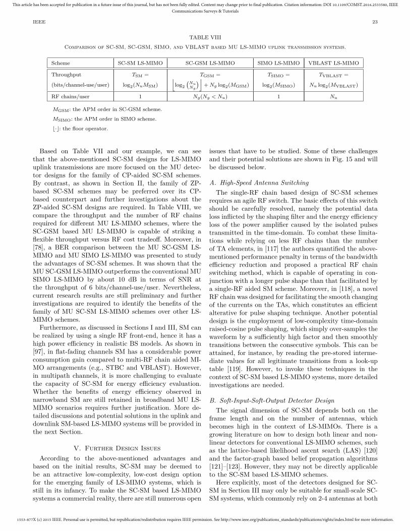
1553-877X (c) 2015 IEEE. Personal use is permitted, but republication/redistribution requires IEEE permission. See http://www.ieee.org/publications_standards/publications/rights/index.html for more information.
This article has been accepted for publication in a future issue of this journal, but has not been fully edited. Content may change prior to final publication. Citation information: DOI 10.1109/COMST.2016.2533580, IEEECommunications Surveys & Tutorials
IEEE 23
TABLE VIII
Comparison of SC-SM, SC-GSM, SIMO, and VBLAST based MU LS-MIMO uplink transmission systems.
Scheme SC-SM LS-MIMO SC-GSM LS-MIMO SIMO LS-MIMO VBLAST LS-MIMO
Throughput TSM = TGSM = TSIMO = TVBLAST =
(bits/channel-use/user) log2(NuMSM)⌊
log2(
NuNg
)⌋+ Ng log2(MGSM) log2(MSIMO) Nu log2(MVBLAST)
RF chains/user 1 Ng(Ng < Nu) 1 Nu
MGSM: the APM order in SC-GSM scheme.
MSIMO: the APM order in SIMO scheme.
⌊·⌋: the floor operator.
Based on Table VII and our example, we can seethat the above-mentioned SC-SM designs for LS-MIMOuplink transmissions are more focused on the MU detec-tor designs for the family of CP-aided SC-SM schemes.By contrast, as shown in Section II, the family of ZP-based SC-SM schemes may be preferred over its CP-based counterpart and further investigations about theZP-aided SC-SM designs are required. In Table VIII, wecompare the throughput and the number of RF chainsrequired for different MU LS-MIMO schemes, where theSC-GSM based MU LS-MIMO is capable of striking aflexible throughput versus RF cost tradeoff. Moreover, in[78], a BER comparison between the MU SC-GSM LS-MIMO and MU SIMO LS-MIMO was presented to studythe advantages of SC-SM schemes. It was shown that theMU SC-GSM LS-MIMO outperforms the conventional MUSIMO LS-MIMO by about 10 dB in terms of SNR atthe throughput of 6 bits/channel-use/user. Nevertheless,current research results are still preliminary and furtherinvestigations are required to identify the benefits of thefamily of MU SC-SM LS-MIMO schemes over other LS-MIMO schemes.
Furthermore, as discussed in Sections I and III, SM canbe realized by using a single RF front-end, hence it has ahigh power efficiency in realistic BS models. As shown in[97], in flat-fading channels SM has a considerable powerconsumption gain compared to multi-RF chain aided MI-MO arrangements (e.g., STBC and VBLAST). However,in multipath channels, it is more challenging to evaluatethe capacity of SC-SM for energy efficiency evaluation.Whether the benefits of energy efficiency observed innarrowband SM are still retained in broadband MU LS-MIMO scenarios requires further justification. More de-tailed discussions and potential solutions in the uplink anddownlink SM-based LS-MIMO systems will be provided inthe next Section.
V. Further Design IssuesAccording to the above-mentioned advantages and
based on the initial results, SC-SM may be deemed tobe an attractive low-complexity, low-cost design optionfor the emerging family of LS-MIMO systems, which isstill in its infancy. To make the SC-SM based LS-MIMOsystems a commercial reality, there are still numerous open
issues that have to be studied. Some of these challengesand their potential solutions are shown in Fig. 15 and willbe discussed below.
A. High-Speed Antenna SwitchingThe single-RF chain based design of SC-SM schemes
requires an agile RF switch. The basic effects of this switchshould be carefully resolved, namely the potential dataloss inflicted by the shaping filter and the energy efficiencyloss of the power amplifier caused by the isolated pulsestransmitted in the time-domain. To combat these limita-tions while relying on less RF chains than the numberof TA elements, in [117] the authors quantified the above-mentioned performance penalty in terms of the bandwidthefficiency reduction and proposed a practical RF chainswitching method, which is capable of operating in con-junction with a longer pulse shape than that facilitated bya single-RF aided SM scheme. Moreover, in [118], a novelRF chain was designed for facilitating the smooth changingof the currents on the TAs, which constitutes an efficientalterative for pulse shaping technique. Another potentialdesign is the employment of low-complexity time-domainraised-cosine pulse shaping, which simply over-samples thewaveform by a sufficiently high factor and then smoothlytransitions between the consecutive symbols. This can beattained, for instance, by reading the pre-stored interme-diate values for all legitimate transitions from a look-uptable [119]. However, to invoke these techniques in thecontext of SC-SM based LS-MIMO systems, more detailedinvestigations are needed.
B. Soft-Input-Soft-Output Detector DesignThe signal dimension of SC-SM depends both on the
frame length and on the number of antennas, whichbecomes high in the context of LS-MIMOs. There is agrowing literature on how to design both linear and non-linear detectors for conventional LS-MIMO schemes, suchas the lattice-based likelihood ascent search (LAS) [120]and the factor-graph based belief propagation algorithms[121]–[123]. However, they may not be directly applicableto the SC-SM based LS-MIMO schemes.
Here explicitly, most of the detectors designed for SC-SM in Section III may only be suitable for small-scale SC-SM systems, which commonly rely on 2-4 antennas at both

1553-877X (c) 2015 IEEE. Personal use is permitted, but republication/redistribution requires IEEE permission. See http://www.ieee.org/publications_standards/publications/rights/index.html for more information.
This article has been accepted for publication in a future issue of this journal, but has not been fully edited. Content may change prior to final publication. Citation information: DOI 10.1109/COMST.2016.2533580, IEEECommunications Surveys & Tutorials
IEEE 24
SC-SM based LS-MIMO system
design issues
Fast antenna
switching
Practical
implementations
SISO
detector
RF chain
reduction
Multi-RF
method
Adaptive
transceiver
po
ten
tial
solu
tio
ns
Channel
estimation
Novel RF
Chain
design
SISO CS
detector
SISO MP
detector
SISO K-
best
detector
Antenna
selection
Other
single-RF
methods
Adaptive
transmitter
Adaptive
receiver
Optimal
preamble
design
Semi-bind
iterative
detection
Differential
method
Small-scale
SM design
extension
Other MIMO
design
extension
Fig. 15. The future design issues and the related potential solutions for the SC-SM based LS-MIMO.
ends of the wireless link. For large-scale SC-SM uplinktransmission, the MP methods were proposed in [105],[112], [113], [124], but they are rely on hard decisions.However, in practice almost all wireless communicationsystems employ some form of FEC for enhancing the datareliability, which requires soft-input soft-output (SISO)detectors for achieving the highest possible coding gain.
Additionally, for the sake of reducing the computationalcomplexity, most of the existing detectors were proposedfor the family of CP-aided SC-SM schemes, where low-complexity single-tap equalization can be used, as shownin Table VII. However, this benefit is achieved under theconstraint of Nt ≤ Nr, which erodes the performance ofSM in asymmetric MIMO systems, routinely encounteredin downlink transmission. In the future, the SISO detectorsdesigned for high-diversity ZP-aided large-scale SC-SMhave to be further investigated.
Since the generalized MP detectors of [105], [112], [113],[124], as well as the CS of [114], [115] and the sparse K-bestdetector of [116] provide significant detection complexityreductions by exploiting the inherent sparsity of the SC-SM-type signaling regime, these SISO versions may indeedbe promising alternatives for SC-SM based LS-MIMOtransmissions and they are worth more intensive study.
C. Further RF Chain ReductionSM may be viewed as a special case of transmit antenna
selection (AS). Unlike the AS techniques conceived for theconventional MIMO systems of [125], which rely on thechannel quality often quantified in terms of the receivedsignal strength, AS in SM is controlled by the incominguser data stream. SM enjoys the prominent benefit thatthe number of RF chains required is substantially reduced.
As shown in Section IV and Table VII, several attractiveTPC schemes have been proposed for SC-SM based LS-MIMO downlink transmission systems [100], [101]. Al-though the AS-like SM scheme can reduce certain parts ofRF chains, they still require a large number of RF chains at
the BS for optimizing the precoder, which may jeopardizethe most salient advantages of SC-SM. To further reducethe associated cost, the classic AS technique can be amal-gamating the concept of SM for reducing the number ofRF chains, without unduly eroding the attainable systemperformance. Especially, when a large number of antennasare used at the BS, the propagation channel potentiallyprovides much more spatial selectivity, than in small-scalescenarios. In this case, the beneficial system performancegain provided by the carefully designed AS schemes willalso become more attractive.
Note that in recent years various AS techniques havebeen proposed for the family of conventional SM schemes[126]–[132]. However, they have been designed for frequen-cy flat-fading scenarios and hence may not be directlyapplicable to the more sophisticated SC-SM scheme. Oneof the key design challenges of AS conceived for SC-SMbased LS-MIMO systems is to construct a beneficial AScriterion, while relying both on a low-complexity and ona modest amount of feedback information. Moreover, arange of other RF chain reduction techniques may becombined with the SC-SM technique, in order to furtherreduce the cost of the hardware as exemplified by thesingle-RF based time-division multiplexing techniques andby the parasitic antenna method of [133].
D. Practical Implementations
Experimental studies have also been conducted for e-valuating the SM-based transceiver in an indoor prop-agation scenario [56], [57], where the BER performanceof small-scale MIMO channels (i.e. the 2 × 2 and the4 × 4 MIMO configurations) operating both in LOS andnon-LOS scenarios was investigated. The measured resultsconfirmed that the theoretical gains predicted by theanalysis are substantiated by the Monte Carlo simulations[56]. Moreover, it was shown in [57] that the SM-basedscheme performs better than the VBLAST and STBC

1553-877X (c) 2015 IEEE. Personal use is permitted, but republication/redistribution requires IEEE permission. See http://www.ieee.org/publications_standards/publications/rights/index.html for more information.
This article has been accepted for publication in a future issue of this journal, but has not been fully edited. Content may change prior to final publication. Citation information: DOI 10.1109/COMST.2016.2533580, IEEECommunications Surveys & Tutorials
IEEE 25
schemes in the context of the measured channel modelsconsidered.
Note that these preliminary results were performed in acontrolled laboratory environment in conjunction with asmall number of antennas, where the effects of dispersivechannels and the impact of the associated hardware im-pairments have not been considered. On the other hand,for conventional LS-MIMO systems, the authors of [134]has provided some experimental results for SC modulationcommunicating over measured massive MIMO channelswith 128 TAs. It was shown that the effects of ISI have tobe carefully considered in conventional LS-MIMO systems,similar to the initial MU SC-SM based LS-MIMO designframework shown in Fig. 13. These observations and in-vestigations may be extended to large-scale MU SC-SMschemes operating in realistic propagation scenarios, so asto verify the related benefits of SC-SM in MU LS-MIMOsystems.
E. Adaptive Transceiver DesignAdaptive transceivers play an important role in wireless
communication systems, which are capable of dynamicallyadjusting the transceiver parameters in response to thetime-variant channel conditions [135], [136]. Hence theyhave been extensively studied in the conventional SMcontext for the sake of improving the achievable BER per-formance and of reducing the detection complexity [137]–[143], whilst relying on adaptive modulation [137], [138],on constellation optimization [54], [139]–[142], on powerallocation [143], [144] as well as on phase rotation tech-niques [145]–[149]. However, it has not been considered,whether these adaptive techniques can be directly appliedto the SC-SM based LS-MIMO systems. Even for theconventional LS-MIMO schemes, only limited initial workhas been disseminated on the design of AS methods andon adaptive receivers [150], [151]. Near-capacity adaptivetechniques, relying on low complexity and a low feedbackrequirement, are worth more intensive study.
F. Channel Estimation and Low-Correlation Preamble Se-quence Design
A key design challenge in LS-MIMO systems (includingSC-SM based LS-MIMO) is how to achieve optimal esti-mation of the CSI. A common approach to acquire CSIis to send properly designed preambles (or pilot signals)from the transmitter(s) and then estimate the channelimpairments in the receiver by correlating the knownpreambles (locally generated) with the received signals.However, this process is always prone to estimation errors.For small-scale SM, the effects of these errors have beeninvestigated in [41], [42], [152]–[155] and it was shownthat SM is more robust to channel estimation errors thanVBLAST. However, this advantage of SM has not beeninvestigated in large-scale SC scenarios.
It is noted that optimal channel estimation in gen-eral requires the preamble sequences to have zero non-trivial auto- and cross-correlations [156]–[159]. However,
the employment of conventional preamble sequences mayjeopardize the advantages of SC-SM, since they have notbeen designed by taking into account the sparse structureof SC-SM symbols. To overcome this impediment, [112]and [113] developed the training sequences by using cyclicright-shifting method for SC-SM based on the MU channelestimation process, which was proposed for uplink LTEtransmissions. However, this design may not be suitablefor high-rate SC-SM schemes, owing to the associatedpower efficiency loss and the pilot overhead imposed. Inall existing MIMO-oriented pilot sequences, the ternary-like pseudo-random sequences of [160] may be a promisingcandidate, including the family of SC-SM and SC-GSMschemes, because its spatial-domain sparsity can be flexi-bly adjusted. Nonetheless, additional work is necessary tomake the associated design more practical.
In order to reduce the pilot-overhead, the semi-blinditerative detection technique of [161], the advanced train-ing optimization techniques of [162] and the differentiallyencoded designs of [163]–[168] may be important futureresearch directions.
VI. Conclusion
In this paper, we reviewed a range of recent researchachievements related to SC-SM, which constitutes a newlow-complexity low-cost broadband MIMO transmissiontechnique recently proposed. This novel scheme is capa-ble of adopting the low-complexity single-stream baseddetection, whilst relying on a single RF chain. Moreover,it can be designed for striking a flexible trade-off amongstthe range of potentially conflicting system requirements,such as the effective throughput, the diversity gain andthe hardware cost, while facilitating communications overdispersive channels. The scheme reviewed here constitutesa promising candidate for LS-MIMO aided MU uplink anddownlink design. However, for exploiting its full benefitsnumerous challenges have to be overcome.
List of Acronyms
ABEP Average Bit Error ProbabilityADCs Analog-to-Digital ConvertorsAPM Amplitude and Phase ModulationAPM-bits Amplitude and Phase Modulation-bitsAS Antenna SelectionBER Bit Error RateBS Base StationCCDF Complementary Cumulative Distribution
FunctionCFO Carrier Frequency OffsetCIR Channel Impulse ResponseCP Cyclic PrefixCS Compressive SensingCSI Channel State InformationDFT Discrete Fourier Transform

1553-877X (c) 2015 IEEE. Personal use is permitted, but republication/redistribution requires IEEE permission. See http://www.ieee.org/publications_standards/publications/rights/index.html for more information.
This article has been accepted for publication in a future issue of this journal, but has not been fully edited. Content may change prior to final publication. Citation information: DOI 10.1109/COMST.2016.2533580, IEEECommunications Surveys & Tutorials
IEEE 26
DFE Decision-Feedback EqualizerEVA Extended Vehicular A ModelFDE Frequency-Domain EqualizationFEC Forward Error CorrectionFH-CDMA Frequency Hopping Code Division
Multiple AccessGSSK Generalized Space Shift KeyingGSM Generalized Spatial ModulationIBI Inter-Block InterferenceIFFT Inverse Fast Fourier TransformKSP Known Symbol PaddingLAS Likelihood Ascent SearchLLRs Log-Likelihood RatiosLOS Line of SightLSA Large-Scale AntennaLS-MIMO Large-Scale Multiple-Input
Multiple-OutputLSS Low-Complexity Single-StreamMAC Multiple Access ChannelMAP Maximum A PosterioriMF Matched FilterMIMO Multiple-Input Multiple-OutputML Maximum-LikelihoodMMSE Minimum Mean-Squared ErrorMP Message PassingMU MultiuserMUI Multiuser-InterferenceOFDM Orthogonal Frequency-Division
MultiplexingPAPR Peak-to-Average Power RatioPIC Parallel Interference CancellationPIC-R-SIC PIC-based Receiver With SICQRD-M QR Decomposition With M -algorithmRA Receive AntennaRF Radio FrequencyRSM Receiver-Side Spatial ModulationSC Single-CarrierSC-FDE Single-Carrier Systems Using
Frequency-Domain EqualizationSC-FDMA Single-Carrier Frequency Division
Multiple AccessSC-SM Single-Carrier-Based Spatial ModulationSD Sphere DecodingSE State EvolutionSER Symbol Error RateSFSK Space Frequency Shift KeyingSIMO Single-Input Multiple-OutputSISO Soft-Input Soft-OutputSIC Successive Interference CancellationSM Spatial ModulationSNR Signal-to-Noise RatioSSK Space Shift KeyingSTdM Space and Time-dispersion ModulationSTBC Space Time Block CodeTA Transmit AntennaTA-bits Transmit Antenna-bitsTDE Time-Domain Equalizer
TEQ Turbo EqualizerTPC Transmit PrecoderVBLAST Vertical Bell Labs Layered Space-TimeZF Zero ForcingZP Zero Padding
References
[1] J. Mietzner, R. Schober, L. Lampe, W. H. Gerstacker,and P. A. Hoeher, “Multiple-antenna techniques for wirelesscommunications–A comprehensive literature survey,” IEEECommun. Surveys Tuts., vol. 11, no. 2, pp. 87-105, SecondQuarter, 2009.
[2] S. Sugiura, S. Chen, and L. Hanzo, “A universal space-timearchitecture for multiple-antenna aided systems,” IEEE Com-mun. Surveys Tuts., vol. 14, no. 2, pp. 401-420, Second Quar-ter, 2012.
[3] L. Zheng and D. N. C. Tse, “Diversity and multiplexing:A fundamental tradeoff in multiple-antenna channels,” IEEETrans. Inf. Theory, vol. 49, no. 5, pp. 1073-1096, May 2003.
[4] B. Hassibi and B. M. Hochwald, “High-rate codes that arelinear in space and time,” IEEE Trans. Inf. Theory, vol. 48,no. 7, pp. 1804-1824, Jul. 2002.
[5] V. Tarokh, H. Jafarkhani, and A. R. Calderbank, “Space-time block codes from orthogonal designs,” IEEE Trans. Inf.Theory, vol. 45, no. 5, pp. 1456-1467, Jul. 1999.
[6] A. Chockalingam and B. S. Rajan, Large MIMO Systems,Cambridge Univ. Press, Feb. 2014.
[7] F. Rusek, D. Persson, B. K. Lau, E. G. Larsson, T. L. Marzetta,O. Edfors, and F. Tufvesson, “Scaling up MIMO: Opportu-nities and challenges with very large arrays,” IEEE SignalProcess. Mag., vol. 30, no. 1, pp. 40-60, Jan. 2013.
[8] T. L. Marzetta, “Noncooperative cellular wireless with unlim-ited numbers of base station antennas,” IEEE Trans. WirelessCommun., vol. 9, no. 11, pp. 3590-3600, Nov. 2010.
[9] A. L. Swindlehurst, E. Ayanoglu, P. Heydari, and F. Capolino,“Millimeter-wave massive MIMO: The next wireless revolu-tion?” IEEE Commun. Mag., vol. 52, no. 9, pp. 56-62, Sept.2014
[10] E. Larsson, O. Edfors, F. Tufvesson, T. Marzetta, “MassiveMIMO for next generation wireless systems,” IEEE Commun.Mag., vol. 52, no. 2, pp. 186-195, Feb. 2014
[11] J. Hoydis, S. ten Brink, and M. Debbah, “Massive MIMO inthe UL/DL of cellular networks: How many antennas do weneed?” IEEE J. Sel. Areas Commun., vol. 31, no. 2, pp. 160-171, Feb. 2013.
[12] K. Zheng, L. Zhao, J. Mei, B. Shao, W. Xiang, and L. Hanzo,“Survey of large-scale MIMO systems,” IEEE Commun. Sur-veys Tuts., vol. 17, no. 3, pp. 1738-1760, Third Quart., 2015.
[13] M. Wu, B. Yu, G. Wang, et al., “Large-scale MIMO detec-tion for 3GPP LTE: algorithms and FPGA implementations,”IEEE J. Sel. Topics Signal Proc., vol. 8, no. 5, pp. 916-929,Oct. 2014.
[14] D. Feng, C. Jiang, G. Lim, L. J. Cimini, Jr., G. Feng, and G.Y. Li, “A survey of energy-efficient wireless communications,”IEEE Commun. Surveys Tuts., vol. 15, no. 1, pp. 167-178, FirstQuart., 2013.
[15] G. Y. Li, Z. K. Xu, C. Xiong, C. Y. Yang, S. Q. Zhang, Y.Chen, and S. G. Xu, “Energy-efficient wireless communication-s: Tutorial, survey, and open issues,” IEEE Wireless Commun.Mag., vol. 18, no. 6, pp. 28-35, Dec. 2011.
[16] R. Y. Mesleh, H. Haas, S. Sinanovic, C. W. Ahn, and S. Yun,“Spatial modulation,” IEEE Trans. Veh. Technol., vol. 57, no.4, pp. 2228-2241, Jul. 2008.
[17] M. Di Renzo, H. Haas, and P. M. Grant, “Spatial modulationfor multiple-antenna wireless systems: A survey,” IEEE Com-mun. Mag., vol. 49, no. 12, pp. 182-191, Dec. 2011.
[18] M. Di Renzo, H. Haas, A. Ghrayeb, S. Sugiura, and L. Hanzo,“Spatial modulation for generalized MIMO: Challenges, oppor-tunities and implementation,” Proceedings of the IEEE, vol.102, no. 1, pp. 56-103, Jan. 2014.
[19] P. Yang, M. Di Renzo, Y. Xiao, S. Li, and L. Hanzo, “Designguidelines for spatial modulation,” IEEE Commun. SurveysTuts., vol. 17, no. 1, pp. 6-26, First Quart., 2015.

1553-877X (c) 2015 IEEE. Personal use is permitted, but republication/redistribution requires IEEE permission. See http://www.ieee.org/publications_standards/publications/rights/index.html for more information.
This article has been accepted for publication in a future issue of this journal, but has not been fully edited. Content may change prior to final publication. Citation information: DOI 10.1109/COMST.2016.2533580, IEEECommunications Surveys & Tutorials
IEEE 27
[20] D. J. Goodman, P. S. Henry, and V. K. Prabhu, “Frequency-hopped multilevel FSK for mobile radio,” Bell Syst. Tech. J.,vol. 59, pp. 1257-1275, Sept. 1980.
[21] T. Kawahara and T. Matsumoto, “Optimum rate reed Solomoncodes for FFH/CDMA mobile radios,” IEE Elec. Letts., vo1.27, no. 21, pp. 2066-2067, 1991.
[22] T. Kawahara and T. Matsumoto, “Optimal rate error protec-tion for coded M-ary FSK FFH/CDMA mobile radio chan-nels,” IEEE 42nd Vehicular Technology Conference (VTC),Denver, CO, 1992, pp. 396-399.
[23] R. Y. Mesleh, H. Haas, C. W. Ahn, and S. Yun, “Spatialmodulation–A new low complexity spectral efficiency enhanc-ing technique,” in IEEE Int. Conf. Commun. Netw. China,Beijing, China, Oct. 2006, pp. 1-5.
[24] R. Y. Mesleh, M. Di Renzo, H. Haas, and P. M. Grant, “Trelliscoded spatial modulation,” IEEE Trans. Wireless Commun.,vol. 9, no. 7, pp. 2349-2361, Jul. 2010.
[25] R. Mesleh, H. Elgala, and H. Haas, “Optical spatial modula-tion,” IEEE/OSA J. Optical Commun. Netw., vol. 3, no. 3, pp.234-244, Mar. 2011.
[26] Y. Yang and B. Jiao, “Information-guided channel-hopping forhigh data rate wireless communication,” IEEE Commun. Lett.,vol. 12, no. 4, pp. 225-227, Apr. 2008.
[27] S. Sugiura, S. Chen, and L. Hanzo, “Generalized space-timeshift keying designed for flexible diversity-, multiplexing- andcomplexity-tradeoffs,” IEEE Trans. Wireless Commun., vol.10, no. 4, pp. 1144-1153, Apr. 2011.
[28] M. D. Renzo and H. Haas, “On transmit diversity for spatialmodulation MIMO: Impact of spatial constellation diagramand shaping filters at the transmitter,” IEEE Trans. Veh.Technol., vol. 62, no. 6, pp. 2507-2531, Jul. 2013.
[29] M. Di Renzo and H. Haas, “Bit error probability of spaceshift keying MIMO over multiple-access independent fadingchannels,” IEEE Trans. Veh. Technol., vol. 60, no. 8, pp. 3694-3711, Oct. 2011.
[30] M. Di Renzo and H. Haas, “Bit error probability of SM-MIMOover generalized fading channels,” IEEE Trans. Veh. Technol.,vol. 61, no. 3, pp. 1124-1144, Mar. 2012.
[31] M. Di Renzo and H. Haas, “Space shift keying (SSK-) MIMOover correlated Rician fading channels: Performance analysisand a new method for transmit-diversity,” IEEE Trans. Com-mun., vol. 59, no. 1, pp. 116-129, Jan. 2011.
[32] M. Di Renzo and H. Haas, “Space shift keying (SSK) modula-tion with partial channel state information: Optimal detectorand performance analysis over fading channels,” IEEE Trans.Commun., vol. 58, no. 11, pp. 3196-3210, Nov. 2010.
[33] E. Başar, Ü. Aygölü, E. Panayırcı, and H. V. Poor, “New trelliscode design for spatial modulation,” IEEE Trans. WirelessCommun., vol. 10, no. 8, pp. 2670-680, Aug. 2011.
[34] ——“Super-orthogonal trellis-coded spatial modulation,” IETCommun., vol. 6, no. 17, pp. 2922-2932, Nov. 2012.
[35] R. Y. Chang, S. J. Lin, and W. H. Chung, “Energy efficienttransmission over space shift keying modulated MIMO chan-nels,” IEEE Trans. Commun., vol. 60, no. 10, pp. 2950-2959,Oct. 2012.
[36] ——, “New space shift keying modulation with Hamming code-aided constellation design,” IEEE Wireless Commun. Lett.,vol. 1, no. 1, pp. 2-5, Feb. 2012.
[37] J. Jeganathan, A. Ghrayeb, L. Szczecinski, and A. Ceron,“Space shift keying modulation for MIMO channels,” IEEETrans. Wireless Commun., vol. 8, no. 7, pp. 3692-3703, Jul.2009.
[38] M. Di Renzo and H. Haas, “A general framework for perfor-mance analysis of space shift keying (SSK) modulation forMISO correlated Nakagami-m fading channels,” IEEE Trans.Commun., vol. 58, no. 9, pp. 2590-2603, Sept. 2010.
[39] M. Di Renzo and H. Haas, “Bit error probability of spacemodulation over Nakagami-m fading: Asymptotic analysis,”IEEE Commun. Lett., vol. 15, no. 10, pp. 1026-1028, Oct. 2011
[40] M. T. Le, V. D. Ngo, H. A. Mai, X. N. Tran, and M. Di Renzo,“Spatially modulated orthogonal space-time block codes withnon-vanishing determinants,” IEEE Trans. Commun., vol. 62,no.1, pp. 85-99, Jan. 2014.
[41] F. S. Al-Qahtani, S.Ikki, M. Di Renzo, and H. Alnuweiri, “Performance analysis of space shift keying modulation with im-perfect estimation in the presence of co-channel interference,”IEEE Commun. Lett., vol. 18, no. 9, pp. 1587-1590, Sept. 2014.
[42] M. Di Renzo, D. De Leonardis, F. Graziosi, and H. Haas,“Space shift keying (SSK-) MIMO with practical channel es-timates” IEEE Trans. Commun., vol. 60, no. 4, pp. 998-1012,Apr. 2012.
[43] M. Di Renzo and H. Haas, “Improving the performance ofspace shift keying (SSK) modulation via opportunistic powerallocation,” IEEE Commun. Lett., vol. 14, no. 6, pp. 500-502,Jun. 2010.
[44] F. S. Al-Qahtani, Y. Huang, M. Di Renzo, S. Ikki, and H.Alnuweiri, “Space shift keying MIMO system under spectrumsharing environments in Rayleigh fading,” IEEE Commun.Lett., vol. 18, no. 9, pp. 1503-1506, Sept. 2014.
[45] N. Serafimovski, S. Sinanovic, M. Di Renzo, and H. Haas, “Multiple access spatial modulation,” EURASIP J. WirelessCommun. Netw., vol. 2012, no. 299, 2012. DOI: 10.1186/1687-1499-2012-299.
[46] A. Stavridis, S. Sinanovic, M. Di Renzo, H. Haas, and P. M.Grant, “An energy saving base station employing spatial mod-ulation” IEEE Int. Workshop on Computer-Aided ModelingAnalysis and Design of Communication Links and Networks,Barcelona, Spain, Sept. 2012, pp. 231-235.
[47] Y. Yang and S. Aissa, “Information-guided transmission indecode-and forward relaying systems: Spatial exploitation andthroughput enhancement,” IEEE Trans. Wireless Commun.,vol. 10, no. 7, pp. 2341-2351, Jul. 2011.
[48] R. Mesleh, S. S. Ikki, E. M. Aggoune and A. Mansour, “Per-formance analysis of space shift keying (SSK) modulation withmultiple cooperative relays,” EURASIP Journal on Advancesin Signal Processing, Sept. 2012
[49] R. Mesleh, S. S. Ikki, and M. Alwakeel, “Performance analysisof space shift keying with amplify and forward relaying,” IEEECommun. Lett., vol. 15, no. 12, pp. 1350-1352, Dec. 2011.
[50] N. Serafimovski, S. Sinanovic, M. Di Renzo, and H. Haas,“Dual-hop spatial modulation (Dh-SM),” in Proc. VTC 2011-Spring, Budapest, Hungary, May 15-18, 2011, pp. 1-5.
[51] K. Unnikrishnan and B. Rajan, “Space-time coded spatialmodulated physical layer network coding for two-way relay-ing,” IEEE Trans. Wireless Commun., vol. 14, no. 1, pp. 331-342, 2015.
[52] P. Yang, S. Li, Y. Xiao, et al, “Detect-and-forward relayingaided cooperative spatial modulation for wireless networks,”IEEE Trans. Commun.,vol. 61, no. 11, pp. 4500-4511, 2013.
[53] A. Stavridis, D. Basnayaka, S. Sinanovic, et al, “A virtualMIMO dual-hop architecture based on hybird spatial modu-lation,” IEEE Trans. Commun., vol. 62, no. 9, pp. 3161-3179,2014.
[54] K. Ntontin, M. Di Renzo, A. I. Perez-Neira, and C. Verikoukis,“Adaptive generalized space shift keying,” EURASIP J. Wire-less Commun. Netw., vol. 2013, no. 43, Feb. 2013.
[55] A. Younis, W. Thompson, M. Di Renzo, C.-X. Wang, M. A.Beach, H. Haas, and P. M. Grant, “Performance of spatialmodulation using measured real-world channels,” IEEE Veh.Technol. Conf. - Fall, Las Vegas, USA, 2013, pp. 1-5.
[56] N. Serafimovski, R. Mesleh, P. Chambers, M. Di Renzo, C.Wang, P. M. Grant, M. A. Beach, and H. Haas, “Practicalimplementation of spatial modulation,” IEEE Trans. Veh.Technol., vol. 62, no. 9, pp. 4511-4523, Nov. 2013.
[57] J. Zhang, Y. Wang, L. Ding, and N. Zhang, “Bit error prob-ability of spatial modulation over measured indoor channels,”IEEE Trans. Wireless Commun., vol. 13, no. 3, pp. 1380-1387,Mar. 2014.
[58] A. Goldsmith, Wireless Communications. Cambridge, U.K.:Cambridge Univ. Press, 2005.
[59] G. L. Stuber, J. Barry, S. McLaughlin, Y. G. Li, M. A. Ingram,and T. Pratt, “Broadband MIMO-OFDM wireless communi-cations,” Proceedings of the IEEE, vol. 92, no. 2, pp. 271-294,Feb. 2004.
[60] M. I. Kadir, S. Sugiura, S. Cheng, and L. Hanzo, “UnifiedMIMO-multicarrier designs: A space-time shift keying ap-proach,” IEEE Commun. Surveys Tuts., vol. 17, no. 2, pp. 550-579, 2015.
[61] B. Muquet, Z. Wang, G. Giannakis, M. de Courville, andP. Duhamel, “Cyclic prefixing or zero padding for wirelessmulticarrier transmissions?” IEEE Trans. Commun., vol. 50,no. 12, pp. 2136-2148, Dec. 2002.
[62] N. Benvenuto, R. Dinis, D. Falconer, and S. Tomasin, “Singlecarrier modulation with nonlinear frequency domain equaliza-

1553-877X (c) 2015 IEEE. Personal use is permitted, but republication/redistribution requires IEEE permission. See http://www.ieee.org/publications_standards/publications/rights/index.html for more information.
This article has been accepted for publication in a future issue of this journal, but has not been fully edited. Content may change prior to final publication. Citation information: DOI 10.1109/COMST.2016.2533580, IEEECommunications Surveys & Tutorials
IEEE 28
tion: An idea whose time has come–again,” Proceedings of theIEEE, vol. 98, no. 1, pp. 69-96, Jan. 2010.
[63] A. Pitarokoilis, S. K. Mohammed, and E. G. Larsson, “On theoptimality of single-carrier transmission in large-scale antennasystems,” IEEE Wireless Commun. Lett., vol. 1, no. 4, Apr.2012.
[64] L. Lu, G. Y. Li, A. L. Swindlehurst, A. Ashikhmin, and R.Zhang, “An overview of massive MIMO: Benefits and chal-lenges,” IEEE J. Sel. Topics Signal Proc., vol. 8, no. 5, pp.742-758, Oct. 2014.
[65] Y. Sheng, Z. Tan, and G. Y. Li, “Single-carrier modulation withML equalization for large-scale antenna systems over RicianFading channels,” IEEE International conference on acoustic,speech and signal processing (ICASSP), Florence, 2014, pp.5759 - 5763.
[66] B. Zhou, Y. Xiao, P. Yang, J. Wang, and S. Li, “Spatialmodulation for single carrier wireless transmission systems,”2011 6th International ICST Conference on Communicationsand Networking in China, Harbin, Aug. 2011, pp. 11-15.
[67] N. Serafimovski, M. Di Renzo, S. Sinanovic, R. Y. Mesleh, andH. Haas, “Fractional bit encoded spatial modulation (FBE-SM),” IEEE Commun. Lett., vol. 14, no. 5, pp. 429-431, May2010.
[68] Y. Yang and S. Aissa, “Bit-padding information guided channelhopping,” IEEE Commun. Lett., vol. 15, no. 2, pp. 163-165,Feb. 2011.
[69] A. G. Orozco-Lugo, M. M. Lara, and D. C. McLernon, “Chan-nel estimation using implicit training,” IEEE Transs. SignalProcess., vol. 52, no. 1, pp. 240-254, Jan. 2004.
[70] P. Som and A. Chockalingam, “Spatial modulation and spaceshift keying in single carrier communication,” in 2012 IEEE23rd International Symposium on PIMRC, Sydney, Sept. 2012,pp. 1991-1996.
[71] R. Rajashekar, K.V.S. Hari, and L. Hanzo, “Spatial modula-tion aided zero-padded single carrier transmission for disper-sive channels,” IEEE Trans. Commun., vol. 61, no. 6, pp. 2318-2329, Jun. 2013.
[72] S. M. Alamouti, “A simple transmit diversity technique forwireless communications,” IEEE J. Sel. Areas Commun., vol.16, no. 8, pp. 1451-1458, Oct. 1998.
[73] J. Fu, C. Hou, W. Xiang, L. Yan, and Y. Hou, “Generalisedspatial modulation with multiple active transmit antennas,”Proc. IEEE GLOBECOM 2010 Workshops, pp. 839-844, Dec.2010.
[74] T. Datta and A. Chockalingam, “On generalized spatial mod-ulation,” Proc. IEEE WCNC 2013, Apr. 2013.
[75] J. Wang, S. Jia, and J. Song, “Generalised spatial modulationsystem with multiple active transmit antennas and low com-plexity detection scheme,” IEEE Trans. Wireless Commun.,vol. 11, no. 4, pp. 1605-1615, Apr. 2012.
[76] J. Jeganathan, A. Ghrayeb, and L. Szczecinski, “Generalizedspace shift keying modulation for MIMO channels,” in Proc.IEEE Int. Symp. Pers., Indoor, Mobile Radio Commun.,Cannes, France, Sep. 2008, pp. 1-5.
[77] S. Sugiura, S. Chen, and L. Hanzo, “Coherent and differentialspace time shift keying: A dispersion matrix approach,” IEEETrans. Commun., vol. 58, no. 11, pp. 3219-3230, Nov. 2010.
[78] T. L. Narasimhan, P. Raviteja, and A. Chockalingam, “Gen-eralized spatial modulation in large-scale multiuser MIMOsystems,” IEEE Trans. Wireless Commun., vol. 24, no. 7, pp.3764-3779, 2015.
[79] J. Zheng and Y. Sun, “Energy-efficient spatial modulation overMIMO frequency selective fading channels,” IEEE Trans. Veh.Technol, vol. 64, no. 5, pp. 2204-2209, 2015.
[80] H. A. Ngo, C. Xu, S. Sugiura, and L. Hanzo, “Space-time-frequency shift keying for dispersive channels,” IEEE SignalProcess. Lett., vol. 18, no. 3, pp. 177-180, Mar. 2011.
[81] A. Younis, N. Serafimovski, R. Mesleh, and H. Haas, “Gen-eralised spatial modulation,” in Proc. Signals, Syst. Comput.,Pacific Grove, CA, Nov. 2010, pp. 1498-1502.
[82] J. G. Proakis, Digital Communications, 4th ed. New York, NY,USA: McGraw-Hill, 2004.
[83] R. W. Heath, Jr. and A. J. Paulraj, “Linear dispersion codesfor MIMO systems based on frame theory,” IEEE Trans. SignalProcess., vol. 50, no. 10, pp. 2429-2441, Oct. 2002.
[84] J. Jeganathan, A. Ghrayeb, and L. Szczecinski, “Spatial mod-ulation: Optimal detection and performance analysis,” IEEECommun. Lett., vol. 12, no. 8, pp. 545-547, Aug. 2008.
[85] S. Sugiura, C. Xu, S. X. Ng, and L. Hanzo, “Reduced-complexity coherent versus non-coherent QAM-aided space-time shift keying,” IEEE Trans. Commun., vol. 59, no. 11, pp.3090-3101, Nov. 2011.
[86] S. Sugiura, S. Chen, and L. Hanzo, “MIMO-aided near-capacity turbo transceivers: Taxonomy and performance versuscomplexity,” IEEE Commun. Surveys Tuts., vol. 14, no. 2, pp.421-442, Second Quart. 2012.
[87] S. Sugiura and L. Hanzo, “Single-RF spatial modulation re-quires single-carrier transmission: frequency-domain turbo e-qualization for dispersive channels,” IEEE Trans. Veh. Tech-nol., vol. 64, no. 10, pp. 4870-4875, 2015.
[88] L. Xiao, D. Lilin, Y. Zhang, Y. Xiao, P. Yang, and S. Li,“A low-complexity detection scheme for generalized spatialmodulation aided single carrier systems,” IEEE Commun.Lett., vol. 19, no. 6, pp. 1069-1072, 2015.
[89] J. Zhang, L. Yang, and L. Hanzo, “Advances in cooper-ative single-carrier FDMA communications: Beyond LTE-Advanced,” IEEE Commun. Surveys Tuts., vol. 17, no. 2, pp.730-756, 2015.
[90] F. Pancaldi, G. Vitetta, R. Kalbasi, N. Al-Dhahir, M. Uysal,and H. Mheidat, “Single-carrier frequency domain equaliza-tion,” IEEE Signal Process. Mag., vol. 25, no. 5, pp. 37-56,Sept. 2008.
[91] A. H. Mehana and A. Nosratinia, “Diversity of MMSE MIMOreceivers,” IEEE Trans. Inf. Theory, vol. 51, no. 11, pp. 6788-6805, Nov. 2012.
[92] O. D. Mohamed, El Hesham, and G. Caire, “On maximum-likelihood detection and the search for the closest latticepoint,” IEEE Trans. Inf. Theory, vol. 47, no. 10, pp. 2389-2402, 2003.
[93] A. Younis, S. Sinanovic, M. Di Renzo, R. Y. Mesleh, and H.Haas, “Generalised sphere decoding for spatial modulation,”IEEE Trans. Commun, vol. 61, no. 7, pp. 2805-2815, Jul. 2013.
[94] L. Hanzo, T. H. Liew, B. L. Yeap, R. Y. S. Tee and S. X. Ng,Turbo Coding, Turbo Equalisation, and Space-Time Coding:EXIT-Chart-aided Near-Capacity Designs for Wireless Chan-nels, 2nd Edition. Hoboken, NJ, USA: Wiley, 2011.
[95] E. Candes, J. Romberg, and T. Tao, “Robust uncertaintyprinciples: Exact signal reconstruction from highly incompletefrequency information,” IEEE Trans. Inf. Theory, vol. 52, no.2, pp. 489-509, Feb. 2006.
[96] D. Donoho, “Compressed sensing,” IEEE Trans. Inf. Theory,vol. 52, no. 4, pp. 1289-1306, 2006.
[97] A. Stavridis, S. Sinanovic, M. Di Renzo, and H. Haas, “En-ergy evaluation of spatial modulation at a multi-antenna basestation,” in Proc. IEEE Veh. Technol. Conf.-Fall, Barcelona,Spain, Sept. 2013, pp. 1-5.
[98] E. Başar, Ü. Aygölü, E. Panayırcı, and H. V. Poor, “Space-timeblock coded spatial modulation,” IEEE Trans. Commun., vol.59, no. 3, pp. 823-832, Mar. 2011.
[99] 3GPP TR36.814, Evolved Universal Terrestrial Radio Access(E-UTRA): Further Advancements for E-UTRA Physical Lay-er Aspects, v. 9.0.0, Mar. 2010.
[100] S. Narayanan, M. J. Chaudhry, A. Stavridis, M. Di Renzo,F. Graziosi, and H. Haas, “Multi-user spatial modulation MI-MO,” in Proc. IEEE WCNC 2014, Istanbul, Apr. 2014, pp.671-676.
[101] K. M. Humadi, A. I. Sulyman, and A. Alsanie, “Spatialmodulation concept for massive multiuser MIMO systems,”International Journal of Antenna and Propagation, vol. 2014,1-9, 2014.
[102] R. Zhang, L. Yang, and L. Hanzo, “Generalised pre-codingaided spatial modulation,” IEEE Trans. Wireless Commun.,vol. 12, no. 11, pp. 5434-5443, 2013.
[103] R. Zhang, L.-L. Yang, and L. Hanzo, “Error probability andcapacity analysis of generalized pre-coding aided spatial mod-ulation,” IEEE Trans. Wireless Commun., vol. 14, no. 1, pp.364-375, Jan. 2015.
[104] A. Stavridis, D. Basnayaka, S. Sinanovic, M. Di Renzo, and H.Haas, “A virtual MIMO dual-hop architecture based on hybridspatial modulation,” IEEE Trans. Commun., vol. 62, no. 9, pp.3161-3179, Sep. 2014.
1553-877X (c) 2015 IEEE. Personal use is permitted, but republication/redistribution requires IEEE permission. See http://www.ieee.org/publications_standards/publications/rights/index.html for more information.
This article has been accepted for publication in a future issue of this journal, but has not been fully edited. Content may change prior to final publication. Citation information: DOI 10.1109/COMST.2016.2533580, IEEECommunications Surveys & Tutorials
IEEE 29
[105] T. L. Narasimhan P. Raviteja, and A. Chockalingam, “Large-scale multiuser SM-MIMO versus massive MIMO,” in Inform.Theory and Applications Workshop (ITA), Feb. 2014, pp. 56-62.
[106] J. Zheng, “Low-complexity detector for spatial modulationmultiple access channels with a large number of receive anten-nas,” IEEE Commun. Letters, vol. 18, no. 11, pp. 2055-2058,Nov 2014.
[107] A. Garcia Rodriguez, C. Masouros, “Low-complexity compres-sive sensing detection for spatial modulation in large-scalemultiple access channels,” IEEE Trans. Commun., vol. 63, no.7, pp. 2565-2579, 2015.
[108] B. J. Frey, Graphical Models for Machine Learning and DigitalCommunication, Cambridge: MIT Press, 1998.
[109] R. J. McEliece, D. J. C. MacKay, and J-F. Cheng, “Turbodecoding as an instance of Pearls “belief propagation” algorith-m,” IEEE J. Sel. Areas Commun., vol. 16, no. 2, pp. 140-152,Feb. 1998.
[110] T. L. Narasimhan and A. Chockalingam, “Channel hardening-exploiting message passing (CHEMP) receiver in large-scaleMIMO systems,” IEEE J. Sel. Topics in Signal Process., vol.8, no. 5, pp. 847-860, Oct. 2014.
[111] B. J. Frey and D. Dueck, “Clustering by passing messagesbetween data points,” Science, vol. 315, pp. 972-976, Feb. 16,2007.
[112] S. Wang, Y. Li, M. Zhao and J. Wang, “Energy efficient andlow-complexity uplink transceiver for massive spatial modula-tion MIMO,” IEEE Trans. Veh. Technol., vol. 64, no. 10, pp.4617-4632, 2015.
[113] S. Wang, Y. Li, and J. Wang, “Multiuser detection in massivespatial modulation MIMO with low-resolution ADCs,” IEEETrans. Wireless Commun., vol. 14, no. 4, pp. 2156-2168, 2015.
[114] C. M. Yu, S. H. Hsieh, H. W. Liang, C. S. Lu, W. H. Chung, S.Y. Kuo, and P. S. Chang, “Compressed sensing detector designfor space shift keying in MIMO systems,” IEEE Commun.Lett., vol. 16, no. 10, pp. 1556-1559, Oct. 2012.
[115] W. Liu, N. Wang, M, J, and H. Xu, “Denoising detection for thegeneralized spatial modulation system using sparse property,”IEEE Commun. Lett., vol. 18, no. 1, pp. 22-25, Jan. 2014.
[116] X. Peng, W. Wu J. Sun, and Y. Liu, “Sparse K-best detectorfor generalised space shift keying in large-scale multiple-input-multiple-output systems,” IET Communications, vol. 9, no. 6,pp. 771-778, 2015.
[117] K. Ishibashi and S. Sugiura, “Effects of antenna switching onband-limited spatial modulation,” IEEE Wireless Commun.Lett., vol. 3, no. 4, pp. 345-348, Apr. 2014.
[118] M. S. Sedaghat, R. R. Mueller, and G. Fischer, “A novelsingle-RF transmitter for massive MIMO,” Smart Antennas(WSA), 2014 18th International ITG Workshop on, Erlangen,Germany, March 2014, pp. 1-8.
[119] L. Hanzo, S. X. Ng, T. Keller, and W. Webb, QuadratureAmplitude Modulation: From Basics to Adaptive Trellis-Coded,Turbo-Equalised and Space-Time Coded OFDM, CDMA andMC-CDMA Systems. John Wiley and IEEE Press, 2004.
[120] K. V. Vardhan, S. K. Mohammed, A. Chockalingam, and B.S. Rajan, “A low-complexity detector for large MIMO systemsand multicarrier CDMA systems,” IEEE J. Sel. Areas Com-mun., vol. 26, no. 3, pp. 473-485, Apr. 2008.
[121] S. K. Mohammed, A. Zaki, A. Chockalingam, and B. S. Ra-jan, “High rate space time coded large-MIMO systems: low-complexity detection and channel estimation,” IEEE J. Sel.Topics Signal Proc., vol. 3, no. 6, pp. 958-974, Dec. 2009.
[122] N. Srinidhi, T. Datta, A. Chockalingam, and B. S. Rajan,“Layered tabu search algorithm for large-MIMO detection anda lower bound on ML performance,” IEEE Trans. Commun.,vol. 59, no. 11, pp. 2955-2963, Nov. 2011.
[123] T. Datta, N. A. Kumar, A. Chockalingam, and B. S. Rajan,“A novel Monte Carlo sampling based receiver for large-scaleuplink multiuser MIMO systems,” IEEE Trans. Veh. Technol.,vol. 62, no. 7, pp. 3019-3038, Sept. 2013.
[124] P. Raviteja, T. L. Narasimhan, and A. Chockalingam, “Detec-tion in large scale multiuser SM-MIMO systems: algorithmsand performance,” in Proc. IEEE VTC 2014-Spring, May2014.
[125] S. Sanayei and A. Nosratinia, “Antenna selection in MIMOsystems,” IEEE Commun. Mag., vol. 42, no. 10, pp. 68-73,Oct. 2004.
[126] P. Zhang, S. Chen, C. Dong, L. Li, and L. Hanzo, “Two-tier channel estimation aided near-capacity MIMO transceiversrelying on norm-based joint transmit and receive antennaselection,” IEEE Trans. Wireless Commun., vol. 14, no. 1, pp.122-137, 2015.
[127] Z. Zhou, N. Ge, and X. Lin, “Reduced-complexity antennaselection schemes in spatial modulation,” IEEE Commun.Lett., vol. 18, no. 1, pp. 14-17, Jun. 2014.
[128] R. Rajashekar, K. V. S. Hari, and L. Hanzo, “Antenna selectionin spatial modulation systems,” IEEE Commun. Lett., vol. 17,no. 3, pp. 521-524, Mar. 2013.
[129] K Ntontin, M. Di Renzo, A. Perez-Neira, and C. Verikoukis,“A low-complexity method for antenna selection in spatialmodulation systems,” IEEE Commun. Lett., vol. 17, no. 12,pp. 2312-2315, Aug. 2013.
[130] N. Wang, W. Liu, H. Men, M. Jin, and H. Xu. “Furthercomplexity reduction using rotational symmetry for EDAS inspatial modulation,” IEEE Commun. Lett., vol. 18, no. 10, pp.1835-1838, 2014.
[131] J. Zheng, “Fast receive antenna subset selection for pre-codingaided spatial modulation,” IEEE Wireless Commun. Lett., vol.4, no. 3, pp. 317-320, 2015.
[132] J. Zheng and J. Chen, “Further complexity reduction for anten-na selection in spatial modulation systems,” IEEE Commun.Lett., vol. 19, no. 6, pp. 937-940, 2015.
[133] A. Mohammadi and F. M. Ghannouchi, “Single RF front-endMIMO transceivers,” IEEE Commun. Mag., vol. 49, no. 12,pp. 104-109, Dec. 2011.
[134] P. Banelli et al., “Modulation formats and waveforms for 5Gnetworks: Who will be the heir of OFDM?: An overview ofalternative modulation schemes for improved spectral efficien-cy,” IEEE Signal Process. Mag., vol. 31, no. 6, pp. 80-93, Nov.2014.
[135] D. J. Love, R. W. Heath, V. K. N. Lau, D. Gesbert, B. D. Rao,and M. Andrews, “An overview of limited feedback in wirelesscommunication systems,” IEEE J. Sel. Areas Commun., vol.26, no. 8, pp. 1341-1365, Oct. 2008.
[136] C. B. Chae, A. Forenza, R. W. Heath, Jr., M. R. Mckay, andI. B. Collings, “Adaptive MIMO transmission techniques forbroadband wireless communication systems,” IEEE Commun.Mag., vol. 48, no. 5, pp. 112-118, May 2010.
[137] P. Yang, Y. Xiao, Y. Yi, and S. Li, “Adaptive spatial modu-lation for wireless MIMO transmission systems,” IEEE Com-mun. Lett., vol. 15, no. 6, pp. 602-604, Jun. 2011.
[138] P. Yang, Y. Xiao, L. Li, Q. Tang, Y. Yu, and S. Li, “Link adap-tation for spatial modulation with limited feedback,” IEEETrans. Veh. Technol., vol. 61, no. 8, pp. 3808-3813, Oct. 2012.
[139] M. Maleki, H. R. Bahrami, S. Beygi, M. Kafashan, and N. H.Tran, “Space modulation with CSI: Constellation design andperformance evaluation,” IEEE Trans. Veh. Technol., vol. 62,no. 4, pp. 1623-1634, May 2013.
[140] M. Maleki, H. R. Bahrami, M. Kafashan, and N. H. Tran, “Onthe performance of spatial modulation: optimal constellationbreakdown,” IEEE Trans. Commun., vol. 62, no. 1, pp. 144-157,Jan. 2014.
[141] C. Masouros and L. Hanzo, “Constellation-randomizationachieves transmit diversity for single-RF spatialmodulation,” IEEE Trans. Veh. Tech., in press, 2015.http://discovery.ucl.ac.uk/1462459/1/Masouros_SM-ConstRand5.pdf.
[142] A. Garcia, C. Masouros and L. Hanzo, “Pre-scaling optimiza-tion for space shift keying based on semidefinite relaxation”IEEE Trans. Commun., vol. 63, no. 11, pp. 4231-4243, 2015.
[143] P. Yang, Y. Xiao, B. Zhang, S. Li, M. El-Hajjar, and L.Hanzo, “Power allocation aided spatial modulation for limited-feedback MIMO systems,” IEEE Trans. Veh. Technol., vol. 64,no. 5, pp. 2198-2204, 2015.
[144] P. Yang, Y. Xiao, S. Li, and L. Hanzo, “A low-complexitypower allocation algorithm for multiple-input multiple-outputspatial modulation systems,” IEEE Trans. Veh. Technol., 2015,in press, DOI: 10.1109/TVT.2015.2410252.
[145] D. Yang, C. Xu, L.-L. Yang, and L. Hanzo, “Transmit-diversity-assisted space-shift keying for colocated and dis-tributed/cooperative MIMO elements,” IEEE Trans. Veh.Technol., vol. 60, no. 6, pp. 2864-2869, Jul. 2011.

1553-877X (c) 2015 IEEE. Personal use is permitted, but republication/redistribution requires IEEE permission. See http://www.ieee.org/publications_standards/publications/rights/index.html for more information.
This article has been accepted for publication in a future issue of this journal, but has not been fully edited. Content may change prior to final publication. Citation information: DOI 10.1109/COMST.2016.2533580, IEEECommunications Surveys & Tutorials
IEEE 30
[146] C. Masouros, “Improving the diversity of spatial modulationin MISO channels by phase alignment,” IEEE Commun. Lett.,vol. 18, no. 5, pp. 729-732, 2014.
[147] P. Yang, Y. Xiao, S. Li, and L. Hanzo, “Phase rotation-basedprecoding for spatial modulation systems,” IET Communica-tions, vol. 9, no. 10, pp. 1315-1323, 2015.
[148] M. S. Veedu, C. R. Murthy, L. Hanzo, “Single-RF spatialmodulation relying on finite-rate phase-only feedback: Designand analysis,” IEEE Trans. Veh. Technol., 2015, in press,DOI:10.1109/TVT.2015.2424960.
[149] P. Yang, Y. L. Guan, Y. Xiao, M. Di. Renzo and S.Li, “Transmit pre-coding aided spatial modulation maxi-mum the minimum Euclidean distance versus minimum theBER,” IEEE Trans. Wireless Commun., 2015, in press,DOI:10.1109/TWC.2015.2497692.
[150] H. Li, L. Song, D. Zhu, and M. Lei, “Energy efficiency of largescale MIMO systems with transmit antenna selection,” in Proc.IEEE Int. Conf. Commun. (ICC), Jun. 2013.
[151] R. Kudo, S. M. D. Armour, J. P. McGeehan, and M. Mizoguchi,“A channel state information feedback method for massiveMIMO OFDM,” IEEE J. Commun. and Netw., vol. 15, no.4, pp. 352-361, Aug. 2013.
[152] E. Başar, Ü. Aygölü, E. Panayırcı, and H. V. Poor, “Per-formance of spatial modulation in the presence of channelestimation errors,” IEEE Commun. Lett., vol. 16, no. 2, pp.176-179, Feb. 2012.
[153] S. S. Ikki and R. Mesleh, “A general framework for performanceanalysis of space shift keying (SSK) modulation in the presenceof Gaussian imperfect estimations,” IEEE Commun. Lett., vol.16, no. 2, pp. 228-230, Feb. 2012.
[154] S. Sugiura and L. Hanzo, “Effects of channel estimation onspatial modulation,” IEEE Signal Process. Lett., vol. 19, no.12, pp. 805-808, Dec. 2012.
[155] X. Wu, H. Claussen, M. Di Renzo, and H. Haas, “Channelestimation for spatial modulation,” IEEE Trans. Commun.,vol. 62, no. 12, pp.4362-4372, Dec. 2014.
[156] Z. Liu, U. Parampalli, and Y. L. Guan, “Optimal odd-lengthbinary Z-complementary pairs,” IEEE Trans. Inf. Theory, vol.60, no. 9, pp. 5768-5781, Jul. 2014.
[157] Z. Liu, Y. Li, and Y. L. Guan, “New constructions of gener-al QAM Golay complementary sequences,”IEEE Trans. Inf.Theory, vol. 59, no. 11, pp. 7684-7692, Nov. 2013.
[158] Z. Liu, Y. L. Guan and U. Parampalli, “New complete com-plementary codes for the peak-to-mean power control in MC-CDMA,” IEEE Trans. Commun., vol. 62, no. 3, pp. 1105-1113,Mar. 2014
[159] Z. Liu, Y. L. Guan and H. H. Chen, “Fractional-delay-resilient receiver for interference-free MC-CDMA communica-tions based on complete complementary codes” IEEE Trans.Wireless Commun., vol. 14, no. 3, pp. 1226-1236, Oct. 2014.
[160] M. El-Fandi, I. A. Henderson, J. McGhee, and P. McGlone,“Uncorrelated multisymbol signals for MIMO system identifi-cation,” IEEE Trans. Instrum. Meas., vol. 47, no. 10, pp. 1133-1138, Oct. 1998.
[161] S. Chen, S. Sugiura, and L. Hanzo, “Semi-blind joint channelestimation and data detection for space-time shift keying sys-tems,” IEEE Signal Process. Lett., vol. 17, no. 12, pp. 993-996,Dec. 2010.
[162] R. Rajashekar, K.V.S. Hari, and L. Hanzo, “Reduced complex-ity ML detection and capacity-optimized training for spatialmodulation systems,” IEEE Trans. Commun., vol. 62, no. 1,pp. 112-125, Jan. 2014.
[163] M. Wen, Z. Ding, X. Cheng, Y. Bian, H. V. Poor, and B. Jiao,“Performance analysis of differential spatial modulation withtwo transmit antennas,” IEEE Commun. Lett., vol. 18, no. 3,pp. 475-478, Mar. 2014.
[164] N. Ishikawa and S. Sugiura, “Unified differential spatial mod-ulation,” IEEE Wireless Commun. Lett., vol. 3, no. 4, pp. 337-340, Feb. 2014.
[165] Y. Bian, X. Cheng, M. Wen, L. Yang, H. V. Poor, and B. Jiao,“Differential spatial modulation,” IEEE Trans. Veh. Technol.,vol. 64, no. 7, pp. 3262-3268, 2015.
[166] M. Wen, X. Cheng, Y. Bian, and H.V. Poor, “A low-complexitynear-ML differential spatial modulation detector,” IEEE Sig-nal Process. Lett., vol. 22, no. 11, pp.1834-1838, Nov. 2015.
[167] P. A. Martin, “Differential spatial modulation for APSK intime-varying fading channels,” IEEE Commun. Lett., vol. 19,no. 7, pp. 1261-1264, Jul. 2015.
[168] L. Xiao, P. Yang, X. Lei, Y. Xiao, and S. Li, “A low-complexitydetection scheme for differential spatial modulation,” IEEECommun. Lett., vol. 19, no. 9, pp. 1516-1519, 2015.
Ping Yang received the PhD degree in 2013from University of Electronic Science andTechnology of China (UESTC). From Sept.2012 to Sept. 2013, he was a visiting studentwith the School of Electronics and Comput-er Science, University of Southampton, UK.From May 2014, he is a Research Fellow inEEE of NTU, Singapore. Also, he is an as-sistant professor at UESTC. His current re-search interests include MIMO/OFDM, ma-chine learning, life science and communication
signal processing.
Yue Xiao received a Ph.D degree in com-munication and information systems from theUniversity of Electronic Science and Tech-nology of China in 2007. He is now an fullprofessor at University of Electronic Scienceand Technology of China. He has publishedmore than 30 international journals and beeninvolved in several projects in Chinese Beyond3G Communication R&D Program. His re-search interests are in the area of wireless andmobile communications.
Yong Liang Guan received his Ph.D. de-gree from the Imperial College of Science,Technology and Medicine, University of Lon-don, in 1997, and B.Eng. degree with firstclass honors from the National Universityof Singapore in 1991. He is now an asso-ciate professor at the School of Electrical andElectronic Engineering, Nanyang Technologi-cal University. His research interests includemodulation, coding and signal processing forcommunication, information security and stor-
age systems. The authorąŕs homepage is available online at http://www3.ntu.edu.sg/home/eylguan.
1553-877X (c) 2015 IEEE. Personal use is permitted, but republication/redistribution requires IEEE permission. See http://www.ieee.org/publications_standards/publications/rights/index.html for more information.
This article has been accepted for publication in a future issue of this journal, but has not been fully edited. Content may change prior to final publication. Citation information: DOI 10.1109/COMST.2016.2533580, IEEECommunications Surveys & Tutorials
IEEE 31
K.V.S. Hari (M’92-SM’97, F’15) received theB.E. degree from Osmania University, Hyder-abad, India, in 1983; the M.Tech. degree fromthe Indian Institute of Technology Delhi, in1985; and the Ph.D. degree from the Univer-sity of California at San Diego, La Jolla, CA,USA, in 1990. Since 1992, he has been withthe Department of Electrical CommunicationEngineering, Indian Institute of Science, Ban-galore, India, where he is currently a Professorand coordinates the activities of the Statistical
Signal Processing Laboratory. He is also, currently, an AffiliatedProfessor with the School of Electrical Engineering, KTH-RoyalInstitute of Technology.
His research interests include the development of signal processingalgorithms for MIMO wireless communication systems, sparse signalrecovery problems, indoor positioning, assistive technologies for theelderly and visual neuroscience.
He has been a Visiting Faculty Member at Stanford University,Stanford, CA, USA; KTH-Royal Institute of Technology, Stockholm,Sweden; and Aalto University Espoo, Finland (formerly HelsinkiUniversity of Technology), During his work at Stanford University,he worked on MIMO wireless channel modeling and is the co-author of the WiMAX standard on wireless channel models for fixed-broadband wireless communication systems, which proposed theStanford University Interim (SUI) channel models. He also workedat DLRL, Hyderabad, and at the Research and Training unit forNavigational Electronics, Osmania University. He is currently anEditor of Elsevier’s EURASIP Journal Signal Processing and theSenior Associate Editor iof Springer’s Indian Academy of SciencesJournal Sadhana.
He is the recipient of the IETE S.V.C. Aiya Award for excellencein Telecom Education and the Distinguished Almnus Award fromthe Osmania University College of Engineering, Hyderabad. He is anAcademic Entrepreneur and a co-Founder of the company ESQUBECommunication Solutions, Bangalore.
A. Chockalingam (S’92-M’93-SM’98) wasborn in Rajapalayam, Tamil Nadu, India. Hereceived the B.E. (Honors) degree in electron-ics and communication engineering from theP. S. G. College of Technology, Coimbatore,India, in 1984, the M.Tech. degree in electron-ics and electrical communications engineering(with specialization in satellite communica-tions) from the Indian Institute of Technology,Kharagpur, India, in 1985, and the Ph.D. de-gree in electrical communication engineering
(ECE) from the Indian Institute of Science (IISc), Bangalore, India,in 1993. During 1986 to 1993, he worked with the Transmission R&Ddivision of the Indian Telephone Industries Limited, Bangalore. FromDecember 1993 to May 1996, he was a Postdoctoral Fellow andan Assistant Project Scientist at the Department of Electrical andComputer Engineering, University of California, San Diego. FromMay 1996 to December 1998, he served Qualcomm, Inc., San Diego,CA, as a Staff Engineer/Manager in the systems engineering group.In December 1998, he joined the faculty of the Department of ECE,IISc, Bangalore, India, where he is a Professor, working in the areaof wireless communications and networking.
Dr. Chockalingam is a recipient of the J. C. Bose National Fel-lowship and the Swarnajayanti Fellowship from the Departmentof Science and Technology, Government of India. He served as anAssociate Editor of the IEEE TRANSACTIONS ON VEHICULARTECHNOLOGY, and as an Editor of the IEEE TRANSACTIONS ONWIRELESS COMMUNICATIONS. He served as a Guest Editor for theIEEE JOURNAL ON SELECTED AREAS IN COMMUNICATIONS(Special Issue on Multiuser Detection for Advanced CommunicationSystems and Networks), and for the IEEE JOURNAL OF SELECTEDTOPICS IN SIGNAL PROCESSING (Special Issue on Soft Detectionon Wireless Transmission). He is a Fellow of the Indian NationalAcademy of Engineering, the National Academy of Sciences, India,the Indian National Science Academy, and the Indian Academy ofSciences.
Shinya Sugiura received the B.S. and M.S.degrees in aeronautics and astronautics fromKyoto University, Kyoto, Japan, in 2002 and2004, respectively, and the Ph.D. degree inelectronics and electrical engineering fromthe University of Southampton, Southampton,U.K., in 2010.
From 2004 to 2012, he was a ResearchScientist with Toyota Central Research andDevelopment Laboratories, Inc., Aichi, Japan.Since 2013, he has been an Associate Professor
with the Department of Computer and Information Sciences, TokyoUniversity of Agriculture and Technology, Tokyo, Japan, where heheads the Wireless Communications Research Group. His researchhas covered a range of areas in wireless communications, networking,signal processing, and antenna technology. He authored or coau-thored over 70 refereed research publications, including 40 IEEEjournal and magazine papers.
Dr. Sugiura was a recipient of a number of awards, including the14th Funai Information Technology Award (First Prize) from the Fu-nai Foundation in 2015, the 28th Telecom System Technology Awardfrom the Telecommunications Advancement Foundation in 2013,the Sixth IEEE Communications Society Asia-Pacific OutstandingYoung Researcher Award in 2011, the 13th Ericsson Young ScientistAward in 2011, and the 2008 IEEE Antennas and PropagationSociety Japan Chapter Young Engineer Award. He was also certifiedas an Exemplary Reviewer of IEEE Communications Letters in 2013and 2014.
Harald Haas (S’98-AM’00-M’03) receivedthe Ph.D. degree from the University of Ed-inburgh in 2001. He currently holds the Chairof Mobile Communications at the Universityof Edinburgh. His main research interests arein optical wireless communications, hybrid op-tical wireless and RF communications, spatialmodulation, and interference coordination inwireless networks. He was an invited speakerat TED Global 2011, and his talk has beenwatched online more than 1.5 million times. He
is Co-founder and Chief Scientific Officer (CSO) of pureLiFi Ltd. Heholds 31 patents and has more than 30 pending patent applications.He has published 300 conference and journal papers including a paperin Science. He was co-recipient of a Best Paper Award at the IEEEVehicular Technology Conference in Las Vegas, NV, USA, in 2013.In 2012, he was the only recipient of the prestigious EstablishedCareer Fellowship from the Engineering and Physical Sciences Re-search Council (EPSRC) within Information and CommunicationsTechnology in the U.K. He is recipient of the Tam Dalyell Prize 2013awarded by the University of Edinburgh for excellence in engagingthe public with science. In 2014, he was selected by EPSRC as oneof ten Recognising Inspirational Scientists and Engineers (RISE)Leaders.

1553-877X (c) 2015 IEEE. Personal use is permitted, but republication/redistribution requires IEEE permission. See http://www.ieee.org/publications_standards/publications/rights/index.html for more information.
This article has been accepted for publication in a future issue of this journal, but has not been fully edited. Content may change prior to final publication. Citation information: DOI 10.1109/COMST.2016.2533580, IEEECommunications Surveys & Tutorials
IEEE 32
Marco Di Renzo (S’05–AM’07–M’09–SM’14) was born in L’Aquila, Italy, in 1978.He received the Laurea (cum laude) and thePh.D. degrees in Electrical and InformationEngineering from the Department of Electricaland Information Engineering, University ofL’Aquila, Italy, in April 2003 and in January2007, respectively. In October 2013, hereceived the Habilitation à Diriger desRecherches (HDR) from the University ofParis–Sud XI, Paris, France.
Since January 2010, he has been a Tenured Academic Researcher(“Chargé de Recherche Titulaire”) with the French National Centerfor Scientific Research (CNRS), as well as a faculty member of theLaboratory of Signals and Systems (L2S), a joint research laboratoryof the CNRS, the École Supérieure d’Électricité (SUPÉLEC) andthe University of Paris–Sud XI, Paris, France. His main researchinterests are in the area of wireless communications theory.
Dr. Di Renzo is the recipient of a special mention for theoutstanding five-year (1997–2003) academic career, Universityof L’Aquila, Italy; the THALES Communications fellowship(2003–2006), University of L’Aquila, Italy; the 2004 Best Spin–OffCompany Award, Abruzzo Region, Italy; the 2006 DEWS TravelGrant Award, University of L’Aquila, Italy; the 2008 Torres QuevedoAward, Ministry of Science and Innovation, Spain; the “Dérogationpour l’Encadrement de Thèse” (2010), University of Paris–SudXI, France; the 2012 IEEE CAMAD Best Paper Award; the 2012IEEE WIRELESS COMMUNICATIONS LETTERS ExemplaryReviewer Award; the 2013 IEEE VTC–Fall Best Student PaperAward; the 2013 Network of Excellence NEWCOM# Best PaperAward; the 2013 IEEE TRANSACTIONS ON VEHICULARTECHNOLOGY Top Reviewer Award; the 2013 IEEE–COMSOCBest Young Researcher Award for Europe, Middle East and Africa(EMEA Region); and the 2014 IEEE ICNC Single Best Paper AwardNomination (Wireless Communications Symposium). Currently, heserves an an Editor of the IEEE COMMUNICATIONS LETTERSand of the IEEE TRANSACTIONS ON COMMUNICATIONS(Wireless Communications – Heterogeneous Networks Modeling andAnalysis).
Christos Masouros (M’06, SM’14), is cur-rently a Lecturer in the Dept. of Electrical& Electronic Eng., University College Lon-don. He received his Diploma in Electrical &Computer Engineering from the University ofPatras, Greece, in 2004, MSc by research andPhD in Electrical & Electronic Engineeringfrom the University of Manchester, UK in 2006and 2009 respectively. He has previously helda Research Associate position in University ofManchester, UK and a Research Fellow posi-
tion in Queen’s University Belfast, UK.He holds a Royal Academy of Engineering Research Fellowship
2011-2016 and is the principal investigator of the EPSRC projectEP/M014150/1 on large scale antenna systems. His research interestslie in the field of wireless communications and signal processing withparticular focus on Green Communications, Large Scale AntennaSystems, Cognitive Radio, interference mitigation techniques forMIMO and multicarrier communications. He was awarded the BestPaper Award in IEEE GlobeCom 2015. He is an Associate Editor forIEEE Communications Letters.
Zilong Liu received his Bachelor degree inthe School of Electronics and Information En-gineering from Huazhong University of Sci-ence and Technology (HUST), Master degreein the Department of Electronic Engineeringfrom Tsinghua University, and Ph.D degree inthe School of Electrical and Electronic Engi-neering, Nanyang Technological University, in2004, 2007 and 2014, respectively. Since July2008, he has been with the School of Electricaland Electronic Engineering, Nanyang Techno-
logical University (NTU), Singapore, first as a Research Associateand since November 2014 a Research Fellow. He was a visitor in theUniversity of Melbourne (UoM) from May 2012 to Feb. 2013 [hostedby Prof. Udaya Parampalli], and a visiting Ph.D student in the HongKong University of Science and Technology (HKUST) from June2013 to July 2013 (hosted by Prof. Wai Ho Mow). He is generallyinterested in coding and signal processing for various communica-tion systems, with emphasis on signal design and algebraic coding,error correction codes, optimal channel estimation, robust/efficientmultiuser communications, and physical layer receiver design. Hishomepage is at http://www.ntu.edu.sg/home/zilongliu/.
Lixia Xiao received the B.E. and M.E. de-grees in 2010 and 2013, respectively from Uni-versity of Electronic Science and Technology ofChina (UESTC). Currently, she is working to-wards the Ph.D. degree in National Key Labo-ratory of Science and Technology on Commu-nications in the same university. Her researchis in the field of wireless communications andcommunication theory. In particular, she isvery interested in signal detection and per-formance analysis of wireless communication
systems.
Shaoqian Li (F’16) received his B.S.E. degreein communication technology from NorthwestInstitute of Telecommunication (Xidian Uni-versity) in 1982 and M.S.E. degree in Commu-nication System from University of ElectronicScience and Technology of China (UESTC)in 1984. He is a Professor, Ph.D supervi-sor, director of National Key Lab of Com-munication,UESTC, and member of Nation-al High Technology R&D Program (863 Pro-gram) Communications Group. His research
includes wireless communication theory, anti-interference technol-ogy for wireless communications, spread-spectrum and frequency-hopping technology, mobile and personal communications.

1553-877X (c) 2015 IEEE. Personal use is permitted, but republication/redistribution requires IEEE permission. See http://www.ieee.org/publications_standards/publications/rights/index.html for more information.
This article has been accepted for publication in a future issue of this journal, but has not been fully edited. Content may change prior to final publication. Citation information: DOI 10.1109/COMST.2016.2533580, IEEECommunications Surveys & Tutorials
IEEE 33
Lajos Hanzo (http://www-mobile.ecs.soton.ac.uk) FREng, FIEEE,FIET, Fellow of EURASIP, DSc received hisdegree in electronics in 1976 and his doctoratein 1983. In 2009 he was awarded the honorarydoctorate “Doctor Honoris Causa” by theTechnical University of Budapest. During his37-year career in telecommunications he hasheld various research and academic posts inHungary, Germany and the UK. Since 1986he has been with the School of Electronics
and Computer Science, University of Southampton, UK, wherehe holds the chair in telecommunications. He has successfullysupervised 80+ PhD students, co-authored 20 John Wiley/IEEEPress books on mobile radio communications totalling in excess of 10000 pages, published 1400+ research entries at IEEE Xplore, actedboth as TPC and General Chair of IEEE conferences, presented
keynote lectures and has been awarded a number of distinctions.Currently he is directing a 100-strong academic research team,working on a range of research projects in the field of wirelessmultimedia communications sponsored by industry, the Engineeringand Physical Sciences Research Council (EPSRC) UK, the EuropeanResearch Council’s Advanced Fellow Grant and the Royal Society’sWolfson Research Merit Award. He is an enthusiastic supporter ofindustrial and academic liaison and he offers a range of industrialcourses. He is also a Governor of the IEEE VTS. During 2008-2012he was the Editor-in-Chief of the IEEE Press and a ChairedProfessor also at Tsinghua University, Beijing. His research is fundedby the European Research Council’s Senior Research Fellow Grant.For further information on research in progress and associatedpublications please refer to http://www-mobile.ecs.soton.ac.ukLajos has 19 000+ citations.