
IEE Science, Education & Technology Division: Chairman's address. Looking for alternatives
11
IEE SCIENCE, EDUCATION & TECHNOLOGY DIVISION: CHAIRMAN'S ADDRESS Looking for alternatives Prof. D.T. Swift-Hook, M.A., M.Sc, Ph.D., F.lnst.P, F.I.M.A., C.Eng., F.I.E.E. Indexing terms Energy conversion and storage, Wind power Abstract: The search for alternative ways of generating and transmitting electricity has always been of concern in the electricity-supply industry. Sometimes this search has proved successful—more often, not. This paper deals with alternative energy sources that are being considered today, with direct energy-conversion processes that were topical twenty years ago and with novel techniques in the power-transmission field, concentrating on ones in which the author has been closely involved: MHD generation, thermoelectrics, HVDC, SF 6 circuit breakers, hydrogen transmission, wave power and wind power. 1 Introduction The search for alternative ways of generating and trans- mitting electricity has always been of concern in the electricity-supply industry, and it will form the subject of this paper. Sometimes the search has proved successful— more often, not. The largest amount of research should, and does, go towards improving existing methods, reducing costs and environmental effects. But technical interest must always be excited by the prospect of doing something a completely different way. The sheer physical scale of power plant nowadays ensures that the impact of any such changes in methods of generation or transmission must be considerable, and perhaps it is that feature which has attracted so many research workers and so much effort in recent decades. At all events, the range of the search is a wide one—so wide that a selection must be made to keep within reason- able bounds for an IEE paper. Topics could be chosen in many ways, but it seems appropriate for the author of a Chairman's address to select ones with which he himself has been involved. If this leads to a rather disparate collec- tion of material, at least the author can present it with enthusiasm and personal conviction. This paper, therefore, deals with alternative energy sources that are being considered today, direct energy- conversion processes that were topical twenty years ago and novel techniques in the power-transmission field, con- centrating on ones in which I have been closely involved. 2 Steam is hard to beat People have generated electricity from steam engines for a very long time, and, from the Victorian era, the public supply of electricity has been powered by steam. There have been a number of developments over the years: the piston engine competed with the turbine at the end of the last century, and in the second half of this century the argument has focused on nuclear boilers versus com- bustion ones, but steam has been a common denominator in the UK. In other parts of the world, water power has made major inroads against steam, but in the UK, although the first power station at Godalming was hydro- electric, there have never been sufficient sources of hydro- power to meet more than a modest part of our need. Gas turbines too have made a very modest contribution, but steam has ruled supreme for nearly a hundred years. Paper 2711A, delivered before the IEE Science, Education & Technology Division on the 20th October 1983 Dr. Swift-Hook is with the Applied Physics Branch, CERL, Kelvin Avenue, Leatherhead, Surrey KT22 7SE, England, and is a Visiting Professor at King's College, London, England 44 Nevertheless, there has always been interest in the possi- bility of generating electricity by alternative means, avoid- ing steam. An upsurge of interest occurred around 1960, perhaps spurred by success in the nuclear field. While fission reactors were demonstrating their capabilities, fusion experiments with Zeta looked promising. The steam cycle had been stretched to its present day limits and beyond. Supercritical plant was being operated, but the problems that emerged showed that particular line of tech- nology was reaching its limits. In fact, the best power-station efficiency in the CEGB has not changed much since the nineteen-sixties. New ther- modynamic processes were sought whose aim was to extract electricity directly from the source of energy 'without the need for moving parts'. Attention focused upon methods of 'direct generation' [1]. Although few figures were ever produced to substantiate the claim, it was felt that moving parts were more costly and less reliable than stationary ones and that the complications of the steam cycle, which had been developed over long periods, were also unnecessarily costly and inefficient. From the thermodynamic point of view, a great deal of the available temperature span seems to be wasted. The flame in a boiler is at 1600°C, and in gas turbines and internal-combustion engines the temperatures can be much higher. On the other hand, in the steam part of the cycle, temperatures are limited to a little more than 600°C. The 1000°C temperature range between these limits does not seem to be used thermodynamically. In fact, this large tem- perature difference provides very high heat-transfer rates, and hence keeps the size of the boiler down to moderate proportions. Even with such large temperature ranges and heat-transfer rates, boilers cost around one third of the total cost of a power station. The maximum efficiency with which heat can be con- verted into electricity is the Carnot efficiency (1 — TJT h ) where the heat is taken in hot at T h and released to a cold sink at T c . The cold temperature at which heat can be rejected in large amounts corresponds to the ambient tem- perature of the air or water from a river or the sea. 27°C is a convenient 'typical' figure to take, since it is also a round number corresponding to 300 K. A steam temperature of more than 600°C corresponds to an absolute temperature of some 900 K, and so the Carnot efficiency is two-thirds. In practice, a little more than half Carnot efficiency can be achieved, and CEGB power stations reach more than 39% from time to time, although the best they can do working the year round is 35.4%. If use can be made of the full temperature of combustion, T h is nearer 1900 K and quite high efficiencies become possible. A quarter more elec- tricity could, in principle, be generated, and work is in hand on various cycles of this sort. IEE PROCEEDINGS, Vol. 131, Pt. A, No. 1, JANUARY 1984
Transcript of IEE Science, Education & Technology Division: Chairman's address. Looking for alternatives

IEE SCIENCE, EDUCATION & TECHNOLOGY DIVISION: CHAIRMAN'S ADDRESS
Looking for alternativesProf. D.T. Swift-Hook, M.A., M.Sc, Ph.D., F.lnst.P, F.I.M.A., C.Eng., F.I.E.E.
Indexing terms Energy conversion and storage, Wind power
Abstract: The search for alternative ways of generating and transmitting electricity has always been of concernin the electricity-supply industry. Sometimes this search has proved successful—more often, not. This paperdeals with alternative energy sources that are being considered today, with direct energy-conversion processesthat were topical twenty years ago and with novel techniques in the power-transmission field, concentrating onones in which the author has been closely involved: MHD generation, thermoelectrics, HVDC, SF6 circuitbreakers, hydrogen transmission, wave power and wind power.
1 Introduction
The search for alternative ways of generating and trans-mitting electricity has always been of concern in theelectricity-supply industry, and it will form the subject ofthis paper. Sometimes the search has proved successful—more often, not. The largest amount of research should,and does, go towards improving existing methods, reducingcosts and environmental effects. But technical interest mustalways be excited by the prospect of doing something acompletely different way. The sheer physical scale of powerplant nowadays ensures that the impact of any suchchanges in methods of generation or transmission must beconsiderable, and perhaps it is that feature which hasattracted so many research workers and so much effort inrecent decades.
At all events, the range of the search is a wide one—sowide that a selection must be made to keep within reason-able bounds for an IEE paper. Topics could be chosen inmany ways, but it seems appropriate for the author of aChairman's address to select ones with which he himselfhas been involved. If this leads to a rather disparate collec-tion of material, at least the author can present it withenthusiasm and personal conviction.
This paper, therefore, deals with alternative energysources that are being considered today, direct energy-conversion processes that were topical twenty years agoand novel techniques in the power-transmission field, con-centrating on ones in which I have been closely involved.
2 Steam is hard to beat
People have generated electricity from steam engines for avery long time, and, from the Victorian era, the publicsupply of electricity has been powered by steam. Therehave been a number of developments over the years: thepiston engine competed with the turbine at the end of thelast century, and in the second half of this century theargument has focused on nuclear boilers versus com-bustion ones, but steam has been a common denominatorin the UK. In other parts of the world, water power hasmade major inroads against steam, but in the UK,although the first power station at Godalming was hydro-electric, there have never been sufficient sources of hydro-power to meet more than a modest part of our need. Gasturbines too have made a very modest contribution, butsteam has ruled supreme for nearly a hundred years.
Paper 2711A, delivered before the IEE Science, Education & Technology Divisionon the 20th October 1983
Dr. Swift-Hook is with the Applied Physics Branch, CERL, Kelvin Avenue,Leatherhead, Surrey KT22 7SE, England, and is a Visiting Professor at King'sCollege, London, England
44
Nevertheless, there has always been interest in the possi-bility of generating electricity by alternative means, avoid-ing steam. An upsurge of interest occurred around 1960,perhaps spurred by success in the nuclear field. Whilefission reactors were demonstrating their capabilities,fusion experiments with Zeta looked promising. The steamcycle had been stretched to its present day limits andbeyond. Supercritical plant was being operated, but theproblems that emerged showed that particular line of tech-nology was reaching its limits.
In fact, the best power-station efficiency in the CEGBhas not changed much since the nineteen-sixties. New ther-modynamic processes were sought whose aim was toextract electricity directly from the source of energy'without the need for moving parts'. Attention focusedupon methods of 'direct generation' [1]. Although fewfigures were ever produced to substantiate the claim, it wasfelt that moving parts were more costly and less reliablethan stationary ones and that the complications of thesteam cycle, which had been developed over long periods,were also unnecessarily costly and inefficient.
From the thermodynamic point of view, a great deal ofthe available temperature span seems to be wasted. Theflame in a boiler is at 1600°C, and in gas turbines andinternal-combustion engines the temperatures can be muchhigher. On the other hand, in the steam part of the cycle,temperatures are limited to a little more than 600°C. The1000°C temperature range between these limits does notseem to be used thermodynamically. In fact, this large tem-perature difference provides very high heat-transfer rates,and hence keeps the size of the boiler down to moderateproportions. Even with such large temperature ranges andheat-transfer rates, boilers cost around one third of thetotal cost of a power station.
The maximum efficiency with which heat can be con-verted into electricity is the Carnot efficiency (1 — TJTh)where the heat is taken in hot at Th and released to a coldsink at Tc. The cold temperature at which heat can berejected in large amounts corresponds to the ambient tem-perature of the air or water from a river or the sea. 27°C isa convenient 'typical' figure to take, since it is also a roundnumber corresponding to 300 K. A steam temperature ofmore than 600°C corresponds to an absolute temperatureof some 900 K, and so the Carnot efficiency is two-thirds.In practice, a little more than half Carnot efficiency can beachieved, and CEGB power stations reach more than 39%from time to time, although the best they can do workingthe year round is 35.4%. If use can be made of the fulltemperature of combustion, Th is nearer 1900 K and quitehigh efficiencies become possible. A quarter more elec-tricity could, in principle, be generated, and work is inhand on various cycles of this sort.
IEE PROCEEDINGS, Vol. 131, Pt. A, No. 1, JANUARY 1984

3 MHD generation
There are, of course, techniques by which combustion tem-peratures can be raised even higher. Preheating of airand/or fuel and oxygen enrichment are methods used on alarge scale in the steel industry and elsewhere. In 1960,when the first attempts at space flight were being made, thetemperatures around 4000°C (the distinction betweendegrees Celsius and Kelvin becomes less important in thatrange!) to be found in rocket combustion chambers excitedconsiderable interest. To find ways of handling such tem-peratures is difficult [2, 3, 4]. Certainly, steam is wellbeyond its useful range, but the fact that flames conductelectricity led to the suggestion that current could beextracted from the flame itself by passing it through a mag-netic field.
When any conductor moves through a magnetic field tocut lines of force, current is generated, as in Fig. 1, and this
electrode
load
generator the basic physics of the generation process is notessentially different from that of a piece of copper movingthrough a magnetic field. In each case the flow of free elec-trons constitutes the current, but the electrical-power engi-neer does not usually need to worry about the microscopicprocesses and atomic collisions. All these effects can besummarised in terms of the conductivity.
The conductivity of a flame is very low [7]. Even whenan easily ionisable material, such as potassium, is added toproduce a reasonable number of free electrons, the conduc-tivity is only one-millionth of that of copper—about thesame as the conductivity of an electrolyte. This means thatthe internal resistance of an MHD generator is muchhigher than that of a more conventional electrical machine.
A major item in any generator is the electromagnet, andserious consideration is being given to developing largesuperconducting magnets for generators. The advantagesof superconductivity for producing large magnetic fieldseconomically were seen very early on in the MHDresearch programme. The Russians rapidly took the leadin the early 1960s in building large MHD power experi-ments, with the Americans concentrating on more sophisti-cated technology. (There were many parallels to this in thespace race). A significant stage was reached when a largesuperconducting magnet, developed in the United States,was flown to Russia for use on their U25 experimentshown in Fig. 3; 25 is the number of megawatts of electri-cal power generated.
insulating ductwall
B
Basic MHD generation configuration
is true whether the conductor is solid, as in a conventionalgenerator, or liquid or gaseous. Gaseous conductors areusually referred to as plasmas. The plasmas considered forfusion power (cf. the Jet project at Culham Laboratories)have temperatures of millions of degrees, but magneto-hydrodynamic power generation [5, 6] is concerned withlow-temperature plasmas, where the temperatures are onlya few-thousand degrees, as shown in Fig. 2. In an MHD Fig. 3 1125 installation in Moscow
Fig. 2 Small scale MHD experimentView through the pole piece of the magnet showing white-hot graphite electrodes in a seeded flame
1EE PROCEEDINGS, Vol. 131, Pi. A, No. 1, JANUARY 1984 45
Such large experiments are essential in MHD gener-ation since wall effects tend to dominate [8]. A per cent, orso of the total energy is lost by friction for every diameterof duct length, and about half as much again owing toheat-transfer losses. The rate at which power can beextracted from the plasma is limited by its low conductivi-ty, the maxium rate being \av2Bz and typically this corre-sponds to only a few per cent, per metre of duct length. Toobtain any reasonable efficiency, therefore, requires ducts ofat least a few metres in length, and, for the losses not todominate the power output, the diameter must be of order1 m. The flow through a rocket nozzle of this size corre-sponds to a substantial fraction of a gigawatt (thermal). Thesituation is in some ways similar to that of a nuclearreactor, which must be of some critical size to overcomeenergy losses at the surface (which are due to neutrons inthe nuclear case) while generating enough power in thevolume.
Instabilities are very familiar in the high-temperatureplasmas found in fusion experiments, but instabilities canalso occur in low-temperature plasmas. In the West thereis a sharp dichotomy between these two fields of research,but in Russia there is not such a clear-cut separation and itwas one of the leading Soviet fusion physicists, Velikhov,who pointed out [9] the instability problems for MHDgeneration. It is common experience that losses tend todamp resonances and stabilise instabilities, so the fear withsmall MHD experiments, in which surface losses mustdominate, is that they may not be representative of the fullscale.
Since realistic experiments must be large, MHDresearch is costly and difficult. For that reason, early en-thusiasm has been somewhat tempered. Nevertheless,experiments are still taking place in Russia, America,Japan, Netherlands, Italy, Hungary and elsewhere.
France and Britain both closed down their substantialMHD research programmes some time ago, but Russiahas proceeded with the construction of a natural-gas fired500 MW plant at Ryazan 600 km south of Moscow to becommissioned within the next few years. The results fromthat plant—economic as well as technical—are awaitedwith great interest by many of us around the world.
4 Thermoelectric power
When MHD activities mushroomed in the early 1960s,there were other contenders for direct generation [1]including fuel cells, thermionic diodes and thermoelectrics.Fuel cells were used to power the spacecraft that flew tothe moon, and so a fair measure of success can be claimedfor them, but it has not proved possible to get their pricesdown far enough for bulk power generation. Electrochemi-cal technology is dealt with by a book in the IEE Energyseries [10] and has now reached the stage where batteriesare being seriously considered for widespread use in motorcars. However, they cannot (yet) compete with pumpedwater as at Dinorwig, or night-storage radiators inpeople's living rooms, in providing storage connected tothe power system.
Thermoelectricity is familiar to any one who has used athermocouple, and in the early nineteen-sixties there wasthe hope [11] that materials could be found with the rightcombination of properties to produce power in significantquantities, i.e. more than the few millivolts and microampsused to measure temperatures. Thermocouples can, ofcourse, be connected in series and/or parallel to provideany convenient combination of current and voltage, butefficiency is a prime consideration for power generation.
46
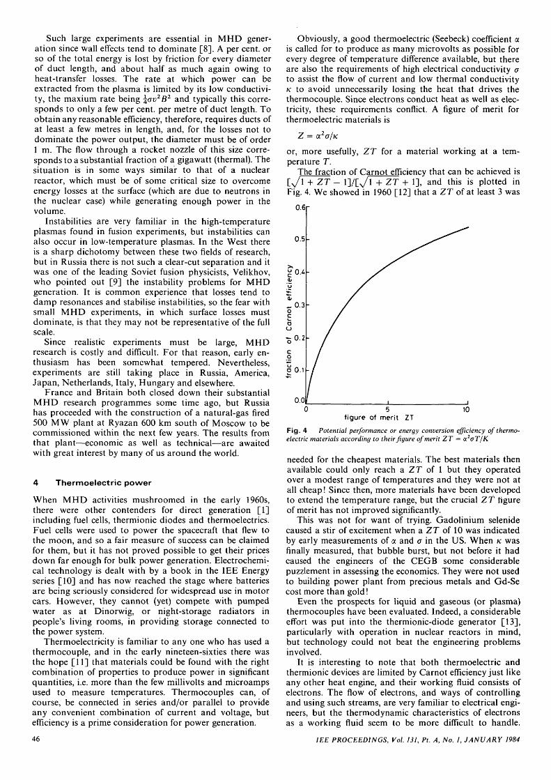
Obviously, a good thermoelectric (Seebeck) coefficient ais called for to produce as many microvolts as possible forevery degree of temperature difference available, but thereare also the requirements of high electrical conductivity ato assist the flow of current and low thermal conductivityK to avoid unnecessarily losing the heat that drives thethermocouple. Since electrons conduct heat as well as elec-tricity, these requirements conflict. A figure of merit forthermoelectric materials is
Z = OL2O/K
or, more usefully, ZT for a material working at a tem-perature T.
The fraction of Carnot efficiency that can be achieved islJTTz~f - l]/r_V 1 + ZT + 1], and this is plotted inFig. 4. We showed in 1960 [12] that a ZT of at least 3 was
0.6r
figure of merit ZT10
Fig. 4 Potential performance or energy conversion efficiency of thermo-electric materials according to their figure of merit ZT = a2aT/K
needed for the cheapest materials. The best materials thenavailable could only reach a ZT of 1 but they operatedover a modest range of temperatures and they were not atall cheap! Since then, more materials have been developedto extend the temperature range, but the crucial ZT figureof merit has not improved significantly.
This was not for want of trying. Gadolinium selenidecaused a stir of excitement when a ZT of 10 was indicatedby early measurements of a and a in the US. When K wasfinally measured, that bubble burst, but not before it hadcaused the engineers of the CEGB some considerablepuzzlement in assessing the economics. They were not usedto building power plant from precious metals and Gd-Secost more than gold!
Even the prospects for liquid and gaseous (or plasma)thermocouples have been evaluated. Indeed, a considerableeffort was put into the thermionic-diode generator [13],particularly with operation in nuclear reactors in mind,but technology could not beat the engineering problemsinvolved.
It is interesting to note that both thermoelectric andthermionic devices are limited by Carnot efficiency just likeany other heat engine, and their working fluid consists ofelectrons. The flow of electrons, and ways of controllingand using such streams, are very familiar to electrical engi-neers, but the thermodynamic characteristics of electronsas a working fluid seem to be more difficult to handle.
IEE PROCEEDINGS, Vol. 131, Pt. A, No. 1, JANUARY 1984

Steam has been around a long time and it is very hard tobeat.
5 Transmission
The search for new methods of generation has beenmatched by the quest for other methods of transmission.Alternating current is universally accepted as the bestmeans of distributing power down to the consumer's level,but AC cables have capacitance and associated dielectriclosses whereas cables carrying DC do not, and so they canbe more efficient as well as cheaper in transferring largequantities of power from point to point. Rectifiers andinverters are required at either end of such a DC link, andthe cost of this terminal plant can only be justified if thedistance is long enough to make the necessary savings overthe life of the installation.
The first major DC link was to Gotland in the middle ofthe Baltic and it is still operating with multigrid mercuryarc valve rectifiers/inverters. Such valves are robust andreliable, well able to withstand voltage spikes and backfirecurrents that would destroy a semiconductor, and they arepotentially capable of considerable development [14, 15].However, developments in semiconductors have ensuredthat all the recent DC installations have used stacks ofthyristors. Thus, the original 160 MW cross-channel linkfrom Lydd to Echingen and the 540 MW Kingsnorth linkinto London used valves, but the 2 000 MW cross-channellink from Sellindge to Les Mandarins (Fig. 5) will havewell protected thryistor stacks.
Canterbury•"I
UK Les, Attaques
FRANCE
Fig. 5
0 10
Cross-channel DC links
Overhead lines are relatively cheap and loss free so thebreak-even distance for DC with AC is hundreds of kilo-metres; overhead DC links are, therefore, found only incountries such as America, Canada and Russia, with vastdistances to cover. Underground or underwater cables aremuch more costly and lossy, so break-even distances aremuch less: around 40 km. Hence the use of HVDC trans-mission across the Channel is economical as well as avoid-ing the need to keep Europe and Britain in sychronism.
There are other possibilities that have been consideredfor high-voltage transmission, including superconductingcables and SF6 (sulphur hexafluoride) or vacuum insulatedlines, but one very different method of transmitting energythat has been seriously proposed involves the use of hydro-gen. Enthusiasts for a complete hydrogen economy envis-age liquid-hydrogen-powered aeroplanes, hydrogen in'bricks' of titanium or magnesium for motor cars andhydrogen to replace natural gas and all other fuels. Amajor advantage claimed for hydrogen is ease of transport,but our detailed studies have shown [16] that, overall,electricity provides a cheaper system than hydrogen. This
is probably one of the important reasons that littleprogress has been made towards the hydrogen economy.
To control the flow of power around a high-voltagetransmission system such as our own grid network, high-power circuit breakers are required and they have to bevery reliable and well tested [17, 18] to protect us whenthe power system is struck by lightning or some similareventuality. In the past, blasts of air and tanks of oil havebeen used to extinguish their arcs. Vacuum is beingactively considered as an alternative, on the principle thatto avoid arcing in the gap between two electrodes com-pletely the best insulating material to use ought to benothing! That contradiction in terms—the vacuum arc—should not exist, but as is often the case in electrical engi-neering, currents can find a way through where they areleast expected. Vacuum switchgear is used successfully atlower voltages in the distribution network, but has not(yet) achieved widespread success on high-power transmis-sion systems.
Early workers [19] demonstrated the merits of SF6
both to hold off volts and to extinguish currents. Nowa-days, SF6 seems well established as the leading contenderfor high-power circuit breakers, but it did not reach thisposition without a fight. Studies of SF6 arcs showed somevery strange phenomena [20], including the 'ball-of-string'instability shown in Fig. 6, and they are difficult to probe
Fig. 6 Ball-of-string instability in an SF6 arc
[21]. However, many of these scientific difficulties arisefrom the electronegative characteristics of SF6 itself and itsarc-products (they attach the free electrons which causebreakdown), and these characteristics are turned to goodengineering advantage in producing SF6 switchgear.
6 Alternative energy
6.1 Alternative sources of powerTwenty years ago the various fuels—coal, gas, oiluranium—were competing actively with one another tomeet a growing need for energy in general and for elec-tricity in particular, and attention was focused uponimproving the efficiencies and economics of their energy-conversion processes. In the last ten years, doubts havearisen concerning the capability of these sources to meetour energy requirements. Sheer quantity is a majorproblem, but other factors such as safety and pollution arealso becoming of increasing concern. The search hasshifted, therefore, towards alternative energy sources [22,23], and the ones of interest to the UK are geothermal,solar, tidal, wave and wind.
IEE PROCEEDINGS, Vol. 131, Pt. A, No. 1, JANUARY 1984 47

6.2 GeothermalWet geothermal power from aquifers is in widespread usearound the world: in Italy, New Zealand, Iceland and else-where. British prospects are modest, since high-temperature aquifers are few, although a borehole in thecoal yard of Marchwood Power Station found some hotwater and one is being bored in the nearby City ofSouthampton to heat their civic centre and Corporationswimming pool. Hot, dry rocks seem to be a better pros-pect, and the Camborne School of Mines are receivingGovernment funds for a major project to break up under-ground rock strata so that heat can be collected by waterpumped down one borehole and brought to the surface assteam via another. If the idea is successful, it can expect tofind widespread application, first of all overseas in coun-tries such as the USA, which are better provided than theUK with hot rocks near the earth's surface.
6.3 Solar PowerPower reaches the earth from the sun in immense quan-tities; more energy arrives in a week or two than the entirereserves of coal, oil and gas laid down throughout geo-logical time. Of course, this energy cannot directly powerour generating plant and so energy conversion is required.Such energy is free and freely available, but the cost ofenergy conversion is high to produce a form that is conve-nient to use, to transport or to store. Solar electricity isparticularly costly, and it seems certain that, apart fromspecial applications such as powering remote repeaters,solar energy will be restricted in the forseeable future toheating applications.
6.4 Tidal powerThe French barrage across the Ranee near St Malo hasgenerated up to 240 MW of power from the tides since1966, but no other scheme has yet followed it. In the UK, abarrage across the Severn has been considered on manyoccasions. Although it has never seemed competitive,recent studies (see Fig. 7) have been quite encouraging.
Berkeleypower
c§/ / stationOldburypowerstation
Bristol
Hinkley pointpower station
Fig. 7 Proposed Severn Barrage
However, the total resource in the Severn, MorecambeBay, Solway Firth and elsewhere around the UK is onlysufficient to provide an output equivalent to two or threepower stations, so its contribution will necessarily belimited even if it could become economic.
7 Wave power
The fortunes of wave power in the field of alternativeenergy have risen and fallen. It was recognised [24] in the
early 1970s that enormous amounts of power come rollingin across the Atlantic with wave heights of 4 m on averagethroughout the year, and more in winter. Every cubicmetre (or tonne) of sea is repeatedly lifted through 4 mabout every 10 s on average, corresponding to a powerflow of 80 kW arriving across every metre width of wavefront. The total resource is several times our electrical-power requirements.
Stephen Salter of Edinburgh University was the firstperson to show in the laboratory that this power could beextracted with high efficiencies [24]. His claims of 85% atfirst seemed incredible at a time when other workers suchas Sir Christopher Cockerell of Hovercraft fame wereachieving only 1% or so, but on careful crosschecking withhim [25] with measurements of standing-wave ratios andtransmitted-wave amplitudes, we found peak efficiencies of95% when the loading was tuned for a particular waveperiod in a particular direction. For a given loading, theefficiency exceeded 50% over a two to one range of periodscorresponding to that found under realistic conditions inthe North Atlantic; a Salter duck is shown in Fig. 8.
Fig. 8 Salter DuckLaboratory tests at Edinburgh University showed very high efficiencies of wave-power extraction [25]
So there is a great deal of power in the waves, and it canbe demonstrated under laboratory conditions that thispower can be extracted with high efficiency. It has sincebeen shown that many different devices, including theCockerell raft, can be tuned to give broadly similar per-formances: a very high resonant efficiency and a good effi-ciency over a broad range of periods of practical interest.The choice between the various devices therefore, calls foran engineering judgement based upon cost and reliability.
This, unfortunately, is the point at which enthusiasm forwave power has faltered. Wave-power devices must with-stand very severe conditions out at sea, or suffer substan-tial loss of power in the waves owing to attenuation inshallow waters if they are sited nearer shore. Although theengineering problems can, no doubt, be solved using off-shore technology, the best estimates available show thatthe solutions will be massive and costly and not very reli-able. Also, real waves at sea are fairly random with neithersingle period nor single direction. Allowing realistically forreal sea conditions, plant losses, outages and availabilities,the resource of wave energy has to be greatly reduced.Faced with somewhat discouraging figures, Governmentsupport for wave-power research is now limited, althoughthe search for cheaper systems continues.
48 IEE PROCEEDINGS, Vol. 131, Pt. A, No. 1, JANUARY 1984

8 Wind power
8.1 The power in the windAs a final topic, let us turn to wind power [26]. Manyengineers feel that they know how windmills work andthat they do not need to take them very seriously. Boththese views are mistaken! It is too early to say whetherwind power will achieve broad economic success, althoughit is already competitive for some specialised applicationssuch as fuel saving on a diesel-powered system. Neverthe-less, it can be considered as a front runner amongst thealternative energies in the UK. While the CEGB has pro-vided host sites (both of them at Marchwood, nearSouthampton) for geothermal and solar-power install-ations and is participating in the national studies of tidaland wave power, two power Boards (CEGB and NSHEB)are actually buying wind-turbine power plant and install-ing it on their power systems.
Incidentally, a useful guide to the seriousness of any dis-cussion in this field is to be found in the terminology.'Windmill' is often used disparagingly and 'wind turbine' ispreferred by the power industry, just as we prefer 'gasturbine' to 'jet engine'.
To continue the discussion seriously, let us considerquantitatively how much power there is the wind, and howmuch of that power a wind turbine can extract.
The kinetic energy of a mass m of air is jmv2 if its speedis v. Per unit volume, mass equates to density, p, so theenergy per unit volume is jpv2 and, since it is blown alongat speed v, the power per unit area in the wind is jpv3, asplotted in Fig. 9. Air is denser at lower temperatures andso cold air carries more power for a given wind speed, but
0.1
0.0110
wind speed, m/s100
Fig. 9 Wind power available at various wind speeds for different coeffi-cients of performancea Total power in wind (100%)b Available power: Betz limit (59.3%)c 40%, d 30%, e 20%, / 10%
at 20°C the power is 0-6y3 per square metre, which isshown in Fig. 9.
It is not possible to extract all of this energy contin-uously. A device that brought the air completely to restwould rapidly become blocked by still air, and the windwould simply be deflected around it so a 100% speedreduction would actually lead to zero efficiency. Evidently,0% speed reduction would likewise give zero efficiency andspeed reductions between these two extremes extractpower at finite efficiencies from the air through the rotorwith a certain amount of deflection around it. Themaximum fraction of energy that can normally beextracted is 16/27 of what would have passed through therotor disc. The air through the rotor is slowed to one-thirdof its initial speed so that 8/9 of its kinetic energy isremoved, but one-third of the air is deflected round therotor so the overall efficiency is less. This maximum 'coeffi-cient of performance' of 59.3% is known as the Betz limitand is shown in Fig. 9b. It cannot, in principle, be exceeded(unless the wind turbine is the centre of a vortex).
Having established how much power is available whenthe wind blows, let us consider just how often it does blow.We require no detailed observations to discover that thewind is very variable, but detailed observations arerequired over long periods to obtain wind-speed-durationcurves such as that shown in Fig. 10a. The straightness ofthe line when it is plotted on log-log against log paper, as
50 100
-30
. a
wind speed , m/h
1 10wind speed , m/s
Fig. 10 Wind-speed-duration curves showing minimum wind speed as afunction of timea with linear scales b log-log against log, or Weibull plot
IEE PROCEEDINGS, Vol. 131, Pt. A, No. 1, JANUARY 1984 49

in Fig. 106, shows [27] that it follows a Weibull distribu-tion. The statistician will note that the second Weibull par-ameter, a shape factor, is usually around 2, correspondingto a cumulative Rayleigh distribution of exp( — x2). Sowind turbines of a given diameter can be highly rated, witha generator that runs at full power for a small part of thetime, or it can generate less power for a greater part of thetime. There is a rather flat optimum, but, in practice, mostmachines are rated at a power level which gives them aload factor of around one-third.
8.2 StorageIt is often suggested that storage systems of various sortscan be associated with such an intermittent source ofpower to convert it into firm power. If the variation werepredictable, as it is for tidal power, that is possible, andtwo basin schemes have been considered for the SevernBarrage although they are less economic. Unfortunately, itis not always appreciated just how firm the power systemis—better than 99.995%—and if the source varies random-ly, the storage requirement becomes completely exorbitant.
That is not to say that storage is not of value in its ownright; the recent opening of the Dinorwig pumped-waterscheme demonstrates that storage is of value to the wholesystem, and many alternatives are being investigated [28].
Variable sources can use the system to provide powerduring their quiescent periods, and they are mainly to beregarded as fuel savers, although they can be credited withsome firm capacity and large amounts of such power couldbe introduced without the need for storage.
lift
drag
blade motion
bladepitchangle
slope
winddirection
Fig. 11 Appropriate forces
a Flying aeroplane wingb Rotating wind turbine blade Slope = blade speed/wind speed
8.3 Wind-turbine design and performanceThe simplest wind device is the Savonius rotor; the adver-tising disc that spins round in the wind from passing carsis a good example. But it has high solidity, i.e. each rotorcovers a large proportion of its swept area. Material costsshould evidently be less for a low-solidity rotor.
A rotating blade can sweep through the air to extractenergy from the full swept area, and it works in very muchthe same way as the flying aeroplane wing shown in Fig.lla. The wing is at some attack angle to the air movingpast. Drag is in the direction of motion through the airand lift at right angles to it, and the geometry of the airflow is the same regardless of the flow speed—until itapproaches the sound barrier.
When a wind-turbine blade is rotating, the picture isjust the same, but the air flow approaching the blade ismade up of two components: the wind itself and the flowpast the blade owing to its motion. The two componentdirections are shown in Fig. l ib superposed upon thenormal lift-drag diagram with the blade moving across thewind as for a normal propellor-type horizontal-axis windturbine. That direction of blade motion is, of course, thedirection in which work is done on the blade by the wind.The slope of the total air-flow direction with respect to thewind direction is the ratio of the blade speed to the windspeed, and so the whole geometry of the air flow is fixedwhen the tip/wind-speed ratio is fixed. That is why the per-formance of a wind turbine is always expressed as a func-tion of the tip/wind-speed ratio, as shown in Fig. 12.
i0.8
blade -tip /wind-speed ratio
Fig. 12 Performance of wind turbines
a Savonius rotorb Multiblade wind pump
,c Old Dutch windmill with 4 blades
10
d Modern 2-blade rotore Darreius vertical axis
0.0
It is interesting to note that the picture is just the samefor the blades of a vertical-axis wind turbine when it ismoving across the wind, and it is only in moving acrossthe wind that useful power is extracted. High-performancewind machines work mainly on lift rather than drag.
Multiblade or high-solidity designs can work at lowwind speeds, and consequently have been widely used forwind pumps. With fewer blades and lower solidity, higherefficiencies can be attained when the blades sweep roundfast enough, i.e. at higher tip/wind-speed ratios. Thecheapest design should be with a single blade, which needsto be statically balanced with a counter-weight, and suchmachines have been built. However, they are not dynami-cally balanced, and so two blades are the minimumnumber usually found. Even a two-bladed rotor is notinherently stable gyroscopically (since the principalmoments of inertia have large differences between them),whereas a three-bladed rotor is. All the instabilities can beavoided—at a cost—with suitably hinged bearings, butthese are only economical on a large scale. So, smaller
50 IEE PROCEEDINGS, Vol. 131, Pt. A, No. 1, JANUARY 1984

wind turbines with rotor diameters up to 50 m often havethree blades with a simple rigid hub while larger onesusually have two blades.
Many different designs of wind turbine have been builtwith modern ones using the latest aerospace technology.Blades making a complete rotation every second or somust undergo millions of cycles each year, perhaps 100million or more gravitational stress reversals in a lifetime,and this presents a very severe fatigue problem indeed.
It has been calculated [29] that the limiting strengths ofmaterials would allow rotors up to 6000 m in diameter tobe built! The practical limit (at least at present) is around100 m generating between 5 MW and 10 MW (see Fig. 13)
wind turbine is complicated, especially when it is appre-ciated that wind-turbine wakes have only recently beenstudied. To extend this understanding to the performanceof a complete array is very difficult indeed, and that area ofbasic research is receiving considerable attention. Wind-tunnel tests on arrays of tiny models (around one-thousandth scale) suggest that 10-diameters spacing shouldbe sufficient to avoid serious loss of power, although buf-feting, owing to turbulence, is still a worry. Field measure-ments [31] have been carried out on small wind turbines,and tests on groups of full-scale machines are just becom-ing possible (Figs. 14 and 15).
Fig. 13 100 m diameter GROW I AN 1 wind turbine built by MAN
Fig. 14 The Central Electricity Generating Board are leading an inter-national team from Holland, Eire and Denmark (with additional fundingfrom the CEC and the UK Department of Energy) to measure wake andinterference effects on the pair of 650 kW, 45 m diameter Danish windturbines at Nibe near Aalborg
although the engineer responsible for the 1951 Costa Headwind turbine, Tom Mensforth, aims to use the 'bicycle-wheel' principle to achieve bigger unit sizes [30].
8.4 ClusteringRotors are mounted with their centres perhaps one diam-eter above the ground, and such constructions are verylarge, but even with the largest units it will still be necess-ary to build hundreds of them to produce the same outputas a single modern power station generating 2000 MW.Some advocate the use of much smaller rotors, perhaps 25 min diameter generating a fraction of a megawatt each. Cer-tainly, the immediate development costs would be less butthen correspondingly larger numbers would be required togenerate significant amounts of power.
As soon as hundreds of machines are considered thequestion arises how close together they can be sited, andthat is a very complex question. It is readily understoodthat wind turbines close to one another will take the windfrom each other's sails. To understand the detailed per-formance of a wind turbine in the wake of even a single
IEE PROCEEDINGS, Vol. 131, Pt. A, No. 1, JANUARY 1984
The prospect of hundreds or thousands of large windturbines covering large areas of countryside may appeardaunting in densely populated countries such as Denmark,Holland and England with no, or relatively few, windyhilltop sites. In fact, the problem may not be very differentfrom finding sites for pylons; 99% of the land between thewind turbines could still be used for agricultural purposes.
8.5 Off-shore wind powerHowever, in case environmental objections do not allowlarge numbers of machines to be sited on land, seriousconsideration is being given to off-shore siting. If shippinglanes, bombing ranges, deep water, very shallow water andother problem areas are avoided, there is still room aroundthe UK for sufficient clusters of wind turbines to generatemore units of electricity per year than does the entireelectrical-power system, see Fig. 16.
Wind energy is two or three times greater off-shore thanon land at rotor height, although the cost of sea-bed foun-dations for individual wind turbines are naturally higherthan on land. There is, therefore, incentive to go for the
51

Fig. 16 Wind-power locations in the British Isles
A 25 m diameter wind turbine is located at Carmarthen Bay (CB) and two atBurgar Hill (BH). Smaller machines are at Aldborough (A), Fair Isle (FI), SouthRonaldsay (SR) and Thurso (TH). Megawatt wind turbines are planned for BurgarHill (BH) and Richborough (R). Measurement masts for wind power assessment arelocated at Carmarthen Bay (CB), Richborough (R), Bradwell (B), Wigsley (W),Belmont Tower (BM), West Sole A gas rig (WS), Askervein Hill (AH) and BurgarHill (BH). Probable offshore locations (black) and possible ones (white) couldprovide a total resource of 366 TWh/a, some 50% more than present demand
Fig. 15 Three 2.5 MWwind turbines, each 91 m indiameter built by Boeingnear Goldendale inWashington State, USA
largest practical size of machine on each base, and theoverall costs may not be very different from those on landwhen such off-shore systems have been developed.
Many individual countries have carried out studies ofoff-shore wind power, including the UK. The CEGB arenow leading a £1 million international collaboration tocarry such studies to the stage at which a prototype couldbe ordered, and we have offered to host such a construc-tion.
8.6 Recent developmentsThe off-shore technology for such developments is prob-ably already available, but the necessary wind-turbinetechnology is still being developed on land. The CentralElectricity Generating Board bought a 25 m diameter 250kW machine in 1982 /or Carmarthen Bay in South Wales(Fig. 17), and the North of Scotland Hydro Electric Boardcommissioned two similar sized machines in 1983 forOrkney Mainland (Fig. 18). Both Boards expect to havemegawatt-sized wind turbines on their systems in 1985, theNSHEB on Orkney and the CEGB at Richborough, Kent,near the site of the ancient Roman port; if all goes well theCEGB subsequently plan to build a group of up to tenmachines by 1990. Worldwide, many large wind turbineshave been built and the latest American designs areclaimed to generate power at less than 3 p/kWh on goodsites and in large numbers (although there is always uncer-tainty about how both money and construction technologycross the Atlantic). If these promises can be fulfilled, windpower should be able to compete with coal, certainly withoil and perhaps even with nuclear power.
9 Conclusion
In recent years there have been sufficient upheavals in oursupplies of, and demand for, power to demonstrate thattoday's 'best buy' may be tomorrow's white elephant.Those with memories long enough to recall our attitudestowards the different energy sources and their economicsbefore we felt the effects of the Yom Kippur war, Three
52 IEE PROCEEDINGS, Vol. 131, Pt. A, No. I, JANUARY 1984

Fig. 17 Wind-turbine generator (WTG) built by Howdens of Glasgowfor the Central Electricity Generating Board at Carmarthen Bay in SouthWales
Mile Island and our own three-day week will realise howrapidly situations can change—much faster than we canbuild power plant. Flexibility is essential to meet an uncer-tain future, and that is particularly true for our powersystem.
At present, nuclear power is the cheapest, cleanest andsafest form of power that we have and the AC grid is thebest way to distribute that power. But no self-respectingengineer can assert what is the 'best' option without havingconsidered, and very seriously considered, the alternatives.For that reason alone, the supply industry has alwayspursued research into new methods of generating, trans-mitting and utilising electricity. Usually the long shots fail;sometimes they succeed: there is no known way of beingsure in advance which ones are which, but when successesdo emerge it is not by guess work but by hard work on thepart of electrical engineers.
10 Acknowledgment
This paper is published with the permission of the CentralElectricity Generating Board.
11 References
1 SPRING, K.H.: 'Direct generation of electricity' (Academic Press,London, 1965)
2 MAYCOCK, J., SWIFT-HOOK, D.T, WRIGHT, J.K, andRAMSDEN, P.: 'Permanent insulating duct walls for an MHD gen-erator', Nature, 1962,196, p. 260
3 MAYCOCK, J., NOE, J.A., and SWIFT-HOOK, D.T.: 'Permanentelectrodes for MHD power generation', Nature, 1962, 193, p. 467
4 BUGDEN, W.F.S., GREEN, L.A., MAYCOCK, J., MEIER, P.G.,and SWIFT-HOOK, D.T.: 'Experimental studies of the performanceof long-lived MHD ducts', in 'Magnetohydrodynamic ElectricalPower Generation' (OECD, Paris, 1964), Vol. 3, p. 1105
Fig. 18 Wind turbine built by the Wind Energy Group (TaylorWoodrow, British Aerospace and GEC) at Burgar Hill for the NSHEBpower system on Orkney Mainland
5 SWIFT-HOOK, D.T.: 'Large scale magnetohydrodynamic powergeneration', Brt. JAP, 1963, 14, p. 69
6 SWIFT-HOOK, D.T.: 'MHD generation' in SPRING, K.H. (Ed.):'Direct generation of electricity' (Academic Press, London, 1965),Chap. 3
7 SWIFT-HOOK, D.T.: 'MHD generation' in SPRING, K.H. (Ed.):'Direct generation of electricity' (Academic Press, London, 1965), p.122
8 SWIFT-HOOK, D.T.: 'Wall effects in an MPD generator' inLINDLEY, B.C. (Ed.): 'Magnetoplasmadynamic electrical power gen-eration' (IEE, London, 1963), p. 22
9 VELIKHOV, Ye.P.: 'Hall instability of current carrying ionizedplasmas' in LINDLEY, B.C. (Ed.): 'Magnetoplasmadynamic electricalpower generation' (IEE, London, 1963), p. 35
10 BARAK, M.: 'Electrochemical power sources: primary and secondarybatteries' (Peter Peregrinus, Stevenage, 1980)
11 WRIGHT, D.A.: 'Thermoelectric generation' in SPRING, K.H. (Ed.):'Direct generation of electricity' (Academic Press, London, 1965),Chap. 5, p. 285
12 SPRING, K.H., and SWIFT-HOOK, D.T.: 'Prospects for large scalethermoelectric power generation', Brit. JAP, 1962, 13, p. 159
13 HARROWELL, R.V.: 'The thermionic converter' SPRING, K.H.(Ed.): 'Direct generation of electricity' (Academic Press, London,1965), Chap. 4, p. 195
14 BLOOMER, R.N., GOZNA, C.F., HARRISON, F.R., and SWIFT-HOOK, D.T.: 'Physical problems in the development of high voltagemercury arc values' in HVDC transmission (IEE, London, 1966), p.186
15 SWIFT-HOOK, D.T.: 'Development of mercury arc values', Elect.Rev., 1966, 180, p. 305
16 HAMPSON, P.J., HART, A.B., SWIFT-HOOK, D.T, SYRETT, J.J.,and WRIGHT, J.K.: 'Can hydrogen transmission replace electricity?'CEGB Res., 1975, 2, p. 4
17 SWIFT-HOOK, D.T.: 'Circuit breaker reliability', Electr. Rev., 1968,182, p. 16
18 SWIFT-HOOK, D.T., and STEEL, J.G.: The statistics of circuitbreakers', Proc. IEE, 1970, 117, p. 7
19 HOWARD, P.R.: 'Insulation properties of compressed electronega-tive gases', ibid., 1957, 104A, pp. 123-138
IEE PROCEEDINGS, Vol. 131, Pt. A, No. 1, JANUARY 1984 53

20 GOZNA, C.F., PALMER, R.T., and SWIFT-HOOK, D.T.: 'Timeconstants near current zero in SF6 arcs'. Proc. Conference on Pheno-mena in Ionized Gases, Beograd, 1966, 3, p. 396
21 GEORGE, D.W., RICHARDS, PH., and SWIFT-HOOK, D.T.:'Boundary conditions in wall stabilised SF6 arc columns'. Proc. Con-ference on Phenomena in Ionized Gases, Vienna, 1967
22 SWIFT-HOOK, D.T.: 'Alternative sources of power', Electron. &Power, 1982, 1, pp. 89-93
23 TAYLOR, R.H.: 'Alternative energy sources for the centralized gener-ation of electricity' (Adam Hilger, Bristol, 1983)
24 SALTER, S.H.: 'Wave power', Nature, 1974, 249, pp. 720-72425 SWIFT-HOOK, D:T., GLENDENNING, I., COUNT, B.H., and
SALTER, S.H., 'Characteristics of a rocking wave power device', ibid.,1975, 254, p. 504
26 BRITISH WIND ENERGY ASSOCIATION, 'Wind energy for theeighties' (Peter Peregrinus, Stevenage, 1982)
27 SWIFT-HOOK, D.T.: 'Describing wind data', Wind Eng., 1979, 3, pp.167-186
28 DAVIDSON, B.J., GLENDENNING, I., HARMAN, R.H., HART,A.B., MADDOCK, B.J., MOFFITT, R.D., NEWMAN, V.G.,SMITH, T.F., WORTHINGTON, P.J., and WRIGHT, J.K., 'Large-scale electrical energy storage', IEE Proc. A, 1980, 127A, pp. 345-385
29 MILBORROW, D.J.: 'Performance, blade loads and size limits forhorizontal axis wind turbines'. BWEA workshop, Cranfield (BHRA,Cranfield, 1982)
30 MENSFORTH, T.: 'Windpower generation on a large scale', FutureEnergy Concepts Conference, IEE, London, 1979
31 SWIFT-HOOK, D.T.: 'A collaborative programme of field measure-ments', BWEA workshop, Cranfield (Multi Science, London, 1979)
54 IEE PROCEEDINGS, Vol. 131, Pt. A, No. 1, JANUARY 1984


![Chairman's Report [Company Update]](https://static.fdocuments.in/doc/165x107/577c777c1a28abe0548c4c79/chairmans-report-company-update.jpg)

