IEC Type Test Report Report No. EU1593-H-00 EVP Polymer ... · Class 3 in Table 5 of IEC 60099-4....
70
IEC Type Test Report Report No. EU1593-H-00 EVP Polymer-housed Arrester 10,000 A Line Discharge Class 3 This report records the results of type tests made on EVP 10 kA Line Discharge Class 3 arresters, rated up to 228 kV. Tests were performed in accordance with procedures of IEC Standard 60099-4, Ed. 2.2, 2009-05, “Surge arresters - Part 4: Metal-oxide surge arresters without gaps for a.c. systems.” To the best of our knowledge and within the usual limits of testing practice, tests performed on these arresters demonstrate compliance with the relevant clauses of the referenced standard. Dennis Lenk Chris Kulig Principal Engineer Product Engineer Date: 5/10/2012 Report No. Description Clause Issue date EU1593-H-01 Insulation withstand test 10.8.2 5/10/2012 EU1593-H-02 Residual Voltage 10.8.3 5/10/2012 EU1593-H-03 Long Duration Current Withstand 10.8.4 5/10/2012 EU1593-H-04 Accelerated Aging Procedure 10.8.5 5/10/2012 EU1593-H-05 Heat Dissipation Behavior of Test Section 10.8.5 5/10/2012 EU1593-H-06 Switching Surge Operating Duty 10.8.5 5/10/2012 EU1593-H-07 Short Circuit 10.8.7 5/10/2012 EU1593-H-08 Internal Partial Discharge 10.8.8 5/10/2012 EU1593-H-09 Bending Moment 10.8.9 5/10/2012 EU1593-H-10 RIV 10.8.12 5/10/2012 EU1593-H-11 Weather Ageing 10.8.14 5/10/2012 EU1593-H-12 Power Frequency Voltage Versus Time Annex D 5/10/2012
Transcript of IEC Type Test Report Report No. EU1593-H-00 EVP Polymer ... · Class 3 in Table 5 of IEC 60099-4....

IEC Type Test Report
Report No. EU1593-H-00
EVP Polymer-housed Arrester
10,000 A Line Discharge Class 3
This report records the results of type tests made on EVP 10 kA Line Discharge Class 3 arresters, rated up to 228 kV. Tests were performed in accordance with procedures of IEC Standard 60099-4, Ed. 2.2, 2009-05, “Surge arresters - Part 4: Metal-oxide surge arresters without gaps for a.c. systems.” To the best of our knowledge and within the usual limits of testing practice, tests performed on these arresters demonstrate compliance with the relevant clauses of the referenced standard.
Dennis Lenk Chris Kulig Principal Engineer Product Engineer
Date: 5/10/2012
Report No. Description Clause Issue date
EU1593-H-01 Insulation withstand test 10.8.2 5/10/2012
EU1593-H-02 Residual Voltage 10.8.3 5/10/2012
EU1593-H-03 Long Duration Current Withstand 10.8.4 5/10/2012
EU1593-H-04 Accelerated Aging Procedure 10.8.5 5/10/2012
EU1593-H-05 Heat Dissipation Behavior of Test Section 10.8.5 5/10/2012
EU1593-H-06 Switching Surge Operating Duty 10.8.5 5/10/2012
EU1593-H-07 Short Circuit 10.8.7 5/10/2012
EU1593-H-08 Internal Partial Discharge 10.8.8 5/10/2012
EU1593-H-09 Bending Moment 10.8.9 5/10/2012
EU1593-H-10 RIV 10.8.12 5/10/2012
EU1593-H-11 Weather Ageing 10.8.14 5/10/2012
EU1593-H-12 Power Frequency Voltage Versus Time Annex D 5/10/2012

IEC Type Test Report
Report No. EU1593-H-01 EVP Series Polymer-housed Arrester
10,000 A Line Discharge Class 3
Insulation Withstand Test on Arrester Housing
This report records the results of type tests made on EVP 10 kA Line Discharge Class 3 arresters, rated up to 228 kV. Tests were performed in accordance with procedures of IEC Standard 60099-4, Ed. 2.2, 2009-05, “Surge arresters - Part 4: Metal-oxide surge arresters without gaps for a.c. systems.” To the best of our knowledge and within the usual limits of testing practice, tests performed on these arresters demonstrate compliance with the relevant clauses of the referenced standard.
Dennis Lenk Chris Kulig Principal Engineer Product Engineer
Date: 5/10/2012

EU1593-H-01 2
Type EVP Station Class Surge Arrester Insulation Withstand
INTRODUCTION: The following table lists the Type EVP arresters’ minimum strike distance, 1.2/50 required and actual impulse withstand levels, and 60 HZ required and actual wet withstand levels as defined in the standard.
CONCLUSION: All housings meet or exceed the required levels of voltage. Arrester
Uc Strike
Distance Lightning Imp W/S
Req'd
Lightning Imp W/S Actual
Switching Imp W/S
Req’d
Switching Imp W/S Actual
60 HZ Wet 1 Minute
Req'd
60 HZ Wet 1 Minute Actual
kVrms mm kVc kVc kVc kVc kVc kVc
2.55 175 10 101 - - 7 71
5.1 175 20 101 - - 13 71
7.65 221 30 127 - - 20 89
8.4 221 32 127 - - 22 89
10.2 221 39 127 - - 27 89
12.7 267 49 153 - - 33 106
15.3 267 59 153 - - 40 106
17 361 66 207 - - 44 143
19.5 361 75 207 - - 51 143
22 361 85 207 - - 57 143
24.4 361 94 207 - - 63 143
29 455 113 261 - - 76 177
31.5 455 122 261 - - 82 177
36.5 546 141 313 - - 95 209
39 546 151 313 - - 101 209
42 546 170 313 - - 114 209
48 640 188 367 - - 126 243
57 734 225 421 - - 152 274
70 1100 282 631 - - 190 389
74 1100 286 631 - - 193 389
76 1100 301 631 - - 203 389
84 1100 340 631 - - 229 389
88 1100 340 631 - - 229 389
98 1135 379 652 - - 255 400
106 1135 413 652 - - 278 400
115 1321 450 758 - - 303 452
131 1613 526 926 - - 354 526
140 1753 541 1006 - - 365 559
144 1753 563 1006 - - 379 559
152 1753 600 1006 - - 404 559
180 2032 713 1166 566 977 - -
(1) Not required

IEC Type Test Report Report No. EU1593-H-02
EVP Series Polymer-housed Arrester 10,000 A Line Discharge Class 3
Residual Voltage
This report records the results of type tests made on EVP 10 kA Line Discharge Class 3 arresters, rated up to 228 kV. Tests were performed in accordance with procedures of IEC Standard 60099-4, Ed. 2.2, 2009-05, “Surge arresters - Part 4: Metal-oxide surge arresters without gaps for a.c. systems.” To the best of our knowledge and within the usual limits of testing practice, tests performed on these arresters demonstrate compliance with the relevant clauses of the referenced standard.
Dennis Lenk Chris Kulig Principal Engineer Product Engineer
Date: 5/10/2012

EU1593-H-02 2
Residual Voltage IEC TYPE TEST REPORT
Residual Voltage TESTS PERFORMED: Residual voltage measurements were made on three single resistor elements. Tests were conducted in accordance with clause 10.8.3 of IEC 60099-4, to determine steep current impulse residual voltages at 10 kA, lightning impulse residual voltages at 5 kA, 10 kA and 20 kA, and switching impulse residual voltages at 0.25 kA and 1 kA. Oscillograms of current and voltage were obtained for each test. For each test sample, all measured voltages have been rationalized to the lightning impulse residual voltage of that sample at nominal discharge current (10 kA 8/20), and the results have been displayed in graphical form. RESULTS: Tables 1, 2 and 3 show the residual voltages measured on test samples 1, 2 and 3, respectively. For each test sample, the measured residual voltages have been expressed in per unit of the lightning impulse residual voltage at nominal discharge current (10 kA, 8/20).
Table 1. Measurements made on test sample 1
Test Wave
Current magnitude
Waveshape Residual Voltage Oscillogram
kA μs kV p.u. number
Steep current
10 1/2 14.583 1.090 34
Lightning impulse
5
8/20
12.471 0.932 7
10 13.385 1.000 10
20 14.452 1.080 13
Switching impulse
0.25 43/91 10.040 0.777 19
1 40/86 11.050 0.826 25
Table 2. Measurements made on test sample 2
Test wave
Current magnitude
Waveshape Residual Voltage Oscillogram
kA Μs kV p.u. number
Steep current
10 1/2 14.545 1.087 35
Lightning impulse
5 8/20
12.465 0.932 8
10 13.380 1.000 11

EU1593-H-02 3
20 14.436 1.079 14
Switching impulse
0.25 43/91 10.358 0.774 20
1 40/86 11.050 0.826 26
Table 3. Measurements made on test sample 3
Test wave Current
magnitude Waveshape Residual Voltage Oscillogram
kA μs kV p.u. number
Steep current
10 1/2 14.596 1.090 36
Lightning impulse
5
8/20
12.479 0.932 9
10 13.396 1.000 12
20 14.478 1.081 15
Switching impulse
0.25 43/91 10.358 0.773 21
1 40/86 11.029 0.823 27
The results are shown graphically in the following chart.
The values shown in this chart are all normalized to the lightning impulse residual voltage at nominal discharge current (10 kA). These values (Per-unit Ures-chart) are used to calculate the residual voltage characteristics (Ures-arrester) of
0.7
0.8
0.9
1
1.1
1.2
0 5 10 15 20
Current - kA
Resid
ual
vo
ltag
e -
p.u
.
Steep impulse
Lightning impulse
Switching impulse

EU1593-H-02 4
assembled PH3 series arresters. For the cases of switching impulse and lightning impulse residual voltages, the arrester residual voltages are calculated as follows:
Ures-arrester = Per-unit Ures-chart x Ures-nom where Ures-nom is the published maximum lightning impulse residual voltage of the arrester, as verified by routine test at time of arrester manufacture. For the case of steep current impulse residual voltage, the arrester residual voltage is calculated as follows:
Ures-arrester = Per-unit Ures-chart x Ures-nom + L’ h In / Tf
where L’ is the inductivity per unit length (= 1 µH/m) h is the length of the arrester (excluding the resistors since resistor inductance is already included in the test measurements) In is the nominal discharge current (= 10 kA) Tf is the front time of the steep current impulse (= 1µs)

EU1593-H-02 5
Oscillograms

EU1593-H-02 6
Oscillogram 7 Sample 1

EU1593-H-02 7
Oscillogram 8 Sample 2

EU1593-H-02 8
Oscillogram 9 Sample 3

EU1593-H-02 9
Oscillogram 10 Sample 1

EU1593-H-02 10
Oscillogram 11 Sample 2

EU1593-H-02 11
Oscillogram 12 Sample 3

EU1593-H-02 12
Oscillogram 13 Sample 1

EU1593-H-02 13
Oscillogram 14 Sample 2

EU1593-H-02 14
Oscillogram 15 Sample 3

EU1593-H-02 15
Oscillogram 19 Sample 1

EU1593-H-02 16
Oscillogram 20 Sample 2

EU1593-H-02 17
Oscillogram 21 Sample 3

EU1593-H-02 18
Oscillogram 25 Sample 1

EU1593-H-02 19
Oscillogram 26 Sample 2

EU1593-H-02 20
Oscillogram 27 Sample 3

EU1593-H-02 21
Oscillogram 34 Sample 1

EU1593-H-02 22
Oscillogram 35 Sample 2

EU1593-H-02 23
Oscillogram 36 Sample 3

IEC Type Test Report
Report No. EU1593-H-03
EVP Polymer-housed Arrester
10,000 A Line Discharge Class 3
Long Duration Current Impulse Withstand Tests
This report records the results of type tests made on EVP series 10 kA Line Discharge Class 3 arresters, rated up to 228 kV. Tests were performed in accordance with procedures of IEC Standard 60099-4, Ed. 2.2, 2009-05, “Surge arresters - Part 4: Metal-oxide surge arresters without gaps for a.c. systems.” To the best of our knowledge and within the usual limits of testing practice, tests performed on these arresters demonstrate compliance with the relevant clauses of the referenced standard.
Dennis Lenk Chris Kulig Principal Engineer Product Engineer
Date: 5/10/2012

EU1593-H-03 2
IEC TYPE TEST REPORT
Long Duration Current Impulse Withstand Tests
TESTS PERFORMED: Long duration current impulse withstand tests were performed on three test samples, each consisting of two resistors (56 mm diameter x 41 mm long) in series. The resistors were selected to represent the lowest acceptable reference voltage level. The tests were conducted in accordance with clause 10.8.4 of IEC 60099-4. Prior to the administering of line discharges, measurements were made of the residual voltage and reference voltage on each test sample. The transmission line parameters conformed to the requirements for Line Discharge Class 3 in Table 5 of IEC 60099-4. Table 1 lists the parameters of the test sections and the corresponding transmission line parameters used for the test. Uc for the EVP series of arresters has been established as 0.795 times the lowest acceptable reference voltage in routine tests, and Ur has been established as 1.25 times Uc . This would normally be represented in the type test by assigning the test sample Uc equal to 0.795 x Uref of the test sample, and test sample Ur at 1.25 times this value . However, in this particular test, Uc was set at a higher value than that used in the actual design (specifically, 0.81 x Uref), thereby making the test more onerous. The minimum energy required for each line discharge for Class 3 arresters is determined from the following formula given in Clause 8.4.2 of IEC 60099-4
W = Ures x (UL – Ures) x 1/Z x T where Ures is the switching impulse residual voltage at 250 A.
Table 1. Parameters for Line Discharge Tests
Parameter Sample
1
Sample
2
Sample
3
Switching impulse residual voltage (kV) Ures Initial Residual Voltage (kV) @ 10 kA, 8/20 Reference Current (mA) Iref
Reference Voltage (kVc / √2) Vref COV ( kV rms) Uc Rating (kV rms) Ur Arrester Classification (kA) Line Discharge Class Virtual Duration of Peak (µs, 90-90%) - min Surge Impedance (Ω) Zg - max (1.3 Ur) Charging Voltage (kV) UL – min (2.8 Ur) Energy required (kJ) - min
20.62 26.67
9.5 11.51 9.33
11.66 10 3
2 400 15.16 32.65 39.3
20.56 26.67
9.5 11.51 9.32
11.65 10 3
2 400 15.15 32.62 39.3
20.64 26.65
9.5 11.50 9.32
11.65 10 3
2 400 15.15 32.62 39.3

EU1593-H-03 3
Each sample was subjected to 18 line discharges, administered in six groups of three discharges. Within each group of three discharges, the time interval between discharges was 50 to 60 seconds. The samples were allowed to cool to ambient temperature between groups of discharges.
RESULTS: A short circuit test was performed on the generator to confirm that generator impedance and duration of the current discharge met the requirements listed in Table 1. The oscillogram of Figure 1 shows
Zg = 13 221 V / 876.38 A = 15.086 Virtual Duration of Peak = 2 453 µs Table 2 lists the current and voltage magnitudes and discharge energy measured on each of the 18 discharges on each of the three test samples. Figures 2, 3 and 4 show oscillograms of the first and eighteenth discharges for each of the three samples, respectively. Ambient air temperature at the time of
the test was 22 C.
Figure 1. Oscillogram of discharge current for generator short circuit set
up test

EU1593-H-03 4
Table 2. Line Discharge Test Measurements
Impulse
Sample 1 Sample 2 Sample 3
I (A) V
(kV)
E
(kJ) I (A)
V
(kV) E (kJ)
I
(A)
V
(kV)
E
(kJ)
1 711 22.18 45.0 765 21.45 46.7 763 21.43 47.1
2 738 21.83 45.9 747 21.78 46.4 742 21.88 46.3
3 717 22.16 45.3 721 22.14 45.7 721 22.22 45.7
4 772 21.51 47.2 774 21.47 47.2 767 21.51 47.0
5 738 21.83 45.9 751 21.85 46.5 740 21.91 46.2
6 744 21.89 46.5 717 22.20 45.7 719 22.28 45.5
7 763 21.51 47.0 763 21.49 46.8 761 21.53 46.9
8 742 21.93 46.1 736 21.87 46.1 738 21.93 46.0
9 719 22.26 45.5 717 22.16 45.4 717 22.24 45.4
10 717 22.42 45.4 772 21.45 46.9 759 21.53 46.7
11 740 21.89 46.1 736 21.89 46.0 740 21.88 46.0
12 717 22.20 45.5 715 22.20 45.5 719 231.88 45.2
13 763 21.51 46.9 763 21.47 46.9 761 21.53 46.8
14 738 21.93 46.0 736 21.91 46.1 736 21.89 45.9
15 717 22.24 45.4 715 22.24 45.5 717 22.28 45.4
16 779 21.56 47.8 770 21.47 47.2 764 21.56 47.0
17 752 21.97 46.9 745 21.85 46.5 745 21.95 46.3
18 724 22.31 46.1 722 22.18 45.8 714 22.24 45.6
Subsequent to the completion of the transmission line discharges, the residual voltage at nominal discharge current was re-measured and compared to the initial values for each test sample. Results are summarized in Table 3. The maximum change of residual voltage of the three samples is less than the permissible change of 5 % defined by IEC 60099-4.
Table 3. Initial and final residual voltage measurements
Sample Residual voltage (kV)
Change Before After
1 26.67 26.65 - 0.08%
2 26.67 26.60 - 0.27%
3 26.65 26.65 0%
Disassembly of the test samples at the end of the electrical tests revealed no evidence of physical damage.

EU1593-H-03 5
Sample 1, Discharge 1
Sample 1, Discharge 18
Figure 2. Oscillograms of line discharges for sample 1

EU1593-H-03 6
Sample 2, Discharge 1
Sample 2, Discharge 18
Figure 3. Oscillograms of line discharges for sample 2

EU1593-H-03 7
Sample 3, Discharge 3
Sample 3, Discharge 18
Figure 4. Oscillograms of line discharges for sample 3

IEC Type Test Report
Report No. EU1593-H-04
EVP Polymer-housed Arrester
10,000 A Line Discharge Class 3
Accelerated Aging Procedure
This report records the results of type tests made on EVP 10 kA Line Discharge Class 3 arresters, rated up to 228 kV. Tests were performed in accordance with procedures of IEC Standard 60099-4, Ed. 2.2, 2009-05, “Surge arresters - Part 4: Metal-oxide surge arresters without gaps for a.c. systems.” To the best of our knowledge and within the usual limits of testing practice, tests performed on these arresters demonstrate compliance with the relevant clauses of the referenced standard.
Dennis Lenk Chris Kulig Principal Engineer Product Engineer
Date: 5/10/2012

EU1593-H-04 2
IEC TYPE TEST REPORT
Accelerated Ageing Procedure
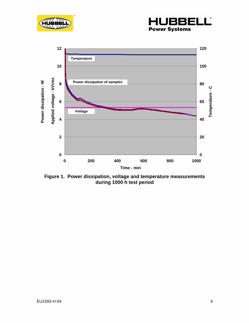
TESTS PERFORMED: Accelerated aging tests were performed on three resistor elements, each 56mm diameter and 41mm long. The tests were conducted in accordance with the requirements of clause 10.8.5 of IEC 60099-4 (requiring the accelerated ageing procedure of clause 8.5.2 to be administered). The test samples were placed in an air oven and energized at a voltage equal to the corrected maximum continuous operating voltage, Uct, for 1000 hours. Uct is the voltage that corresponds to the maximum voltage to which a resistor would be subjected in a complete arrester, taking into account non-uniform voltage distribution along the arrester length. EVP arresters are designed such that the maximum voltage stress at any point along the resistor column is not more than 1.15 times the average stress along the column.
The temperature of the samples was maintained at 115 C 2 C for the duration of the test. Power dissipation was measured on each sample throughout the 1000 h test period. Clause 8.5.2 of IEC 60099-4 defines three power dissipation values:
P1ct, measured 1 h to 2 h after the initial voltage application
P2ct, measured after 1000 h
P3ct, the minimum value attained during the 1000 h test period. If P2ct is equal to or less than 1.1 times P3ct, then the switching surge operating duty test of Clause 8.5.5 of IEC 60099-4 is to be performed on new resistors. Furthermore, if P2ct is equal to or less than P1ct, then the rated voltage and continuous operating voltage used for the operating duty test are not subject to any modification.

EU1593-H-04 3
RESULTS: Table 1 lists sample characteristics and calculated minimum test voltage Uct. The test voltage was set to 5.30 kVrms
Table 1. Parameters for accelerated ageing test
Sample 1 Sample 2 Sample 3
Reference current - mA 9.5 9.5 9.5
Reference voltage, Uref – kVpk/√2
5.76 5.75 5.74
Uc (0.795 x Uref) - kVrms 4.58 4.57 4.56
Uct (1.15 x Uc) - kVrms 5.27 5.26 5.25
Figure 1 graphically displays the measurements made during the 1000 h test period. Table 1 summarizes the values of P1ct, P2ct and P3ct for each sample. The requirements that P2ct is equal to or less than 1.1 times P3ct, and P2ct is equal to or less than P1ct are met for all three samples. Consequently, no modification needs to be made to the rated voltage and continuous operating voltage in the operating duty test, and the operating duty test can be performed on new resistors.
Table 2. Power dissipation values
Sample
Number
Power dissipation
at 2 h
Power dissipation
at 1000 h
Minimum power
dissipation
P1ct (W) P2ct (W) P3ct (W)
1 6.39 4.11 4.11
2 6.36 4.11 4.11
3 6.17 4.01 4.01
EU1593-H-04 4
0
2
4
6
8
10
12
0 200 400 600 800 1000
Time - min
Po
wer
dis
sip
ati
on
- W
Ap
pli
ed
vo
ltag
e -
kV
rms
0
20
40
60
80
100
120
Tem
pera
ture
- C
Temperature
Voltage
Power dissipation of samples
Figure 1. Power dissipation, voltage and temperature measurements
during 1000 h test period

IEC Type Test Report
Report No. EU1593-H-05
EVP Polymer-housed Arrester
10,000 A Line Discharge Class 3
Heat Dissipation Behaviour of Test Section
This report records the results of type tests made on EVP 10 kA Line Discharge Class 3 arresters, rated up to 228 kV. Tests were performed in accordance with procedures of IEC Standard 60099-4, Ed. 2.2, 2009, “Surge arresters - Part 4: Metal-oxide surge arresters without gaps for a.c. systems.” To the best of our knowledge and within the usual limits of testing practice, tests performed on these arresters demonstrate compliance with the relevant clauses of the referenced standard.
Dennis Lenk Chris Kulig Principal Engineer Product Engineer
Date: 5/10/2012

EU1593-H-05 2
IEC TYPE TEST REPORT
Heat Dissipation Behaviour of Test Section
INTRODUCTION: Tests were performed as required by clause 10.8.5 of IEC 60099-4 and Appendix B as defined in 37/391/CD, to compare the cooling characteristics of the test section used for type tests with those of a full-size arrester unit.
PURPOSE: The purpose of this test is to verify that the thermal cooling curve for the Type EVP prorated section, when internally heated, will cool slower than that of a full size EVP arrester unit.
PROCEDURE: A full size single unit 72 kV rated EVP arrester and a prorated section were heated up by applying a temporary overvoltage to the test samples. Per 37/391/CD, both samples (the arrester and the prorated section) were energized in approximately 10 minutes to a starting temperature of 140 ºC, at which time the voltage was removed. Both samples were instrumented with (1) fiber-optic sensors located in the middle of the MOV disc stack. During the cooling portion of the test, the temperature of the arrester and the test section were monitored at 5 minute intervals to develop the arrester unit cooling curve. Per 37/391/CD, the cooling rate during the 1
st 15 minutes was slower for the
EVP section than the arrester. To assure thermal equivalency, as allowed by the standard, the starting temperature of the section cooling curve was raised from the targeted 140 ºC point (for the arrester) to 147.7 ºC for the prorated section.

EU1593-H-05 3
SUMMARY: The following cooling curve confirms that the cooling rate of the EVP prorated section is slower than that of the full size EVP arrester unit, confirming the thermal equivalency of the prorated section to the full size arrester.

IEC Type Test Report
Report No. EU1593-H-06
EVP Polymer-housed Arrester
10,000 A Line Discharge Class 3
Switching Surge Operating Duty Test
This report records the results of type tests made on EVP 10 kA Line Discharge Class 3 arresters, rated up to 228 kV. Tests were performed in accordance with procedures of IEC Standard 60099-4, Ed. 2.2, 2009, “Surge arresters - Part 4: Metal-oxide surge arresters without gaps for a.c. systems.” To the best of our knowledge and within the usual limits of testing practice, tests performed on these arresters demonstrate compliance with the relevant clauses of the referenced standard.
Dennis Lenk Chris Kulig Principal Engineer Product Engineer
Date: 5/10/2012

EU1593-H-06 2
IEC TYPE TEST REPORT
Switching Surge Operating Duty Test
TESTS PERFORMED: Switching surge operating duty tests, in accordance with the requirements of clause 10.8.5 of IEC 60099-4, were performed on three prorated test sections. The test sections were prepared based on the results of the tests to verify heat dissipation behavior of test sample (see EU1593-H-05 section of EVP type test report). Each section consisted of two resistors (56 mm diameter, 41 mm long) in series. The resistors were selected to represent the lowest acceptable reference voltage level. Prior to the conditioning portion of the test, measurements were made of the lightning impulse residual voltage of each section, and also of reference voltage of each section. The conditioning portion of the test consisted of two parts. In the first part, a series of twenty 8/20 lightning current impulses was applied to each section, with peak value of the impulses being equal to the nominal discharge current. The series of impulses was divided into four groups of five, with the interval between impulses within each group being between 50 and 60 seconds and the interval between groups being between 25 and 30 minutes. Test sections
were energized at 60 Hz voltage of 1.2 Uc during the application of the impulses within each
group. The impulses were timed to occur 60 before the crest of the 60 Hz voltage with the same polarity of the impulse. In the second part, a series of two 100kA 4/10 impulses were applied to each section, with the section allowed to cool to ambient temperature between impulses. Following the conditioning portion of the test, each section was placed in an oven and heated
overnight to 68 C per thermal equivalency design test. After removal from the oven, each section was subjected to two long duration current impulses, with time between impulses being between 50 and 60 seconds. The parameters of the transmission line used to generate these impulses conformed to the requirements for Line Discharge Class 4 in Table 5 of Clause 8.4.2 of IEC 60099-4. Within 100 milliseconds of the second long duration current impulse, rated voltage (Ur) was applied to each section for 10 seconds, immediately followed by Uc for 30 minutes, during which period the power dissipation was monitored to verify thermal stability. At the end of the above test sequence, each section was allowed to cool to ambient temperature, at which point the lightning impulse residual voltage at nominal discharge current was re-measured. Table 1 lists the parameters of the test sections and the corresponding transmission line parameters used for the test. Uc for the EVP series of arresters has been established as 0.795 times the lowest acceptable reference voltage in routine tests, and Ur has been established as 1.25 times Uc . This is represented in this type test by assigning the test sample Uc equal to 0.795 x Uref of the test sample, and test sample Ur at 1.25 times this value . The minimum energy required for each line discharge for Class 3 arresters is determined from the following formula given in Clause 8.4.2 of IEC 60099-4
W = Ures x (UL – Ures) x 1/Z x T where Ures is the switching impulse residual voltage at 250 A.

EU1593-H-06 3
Table 1. Initial Measurements and Parameters for Line Discharge Tests
Parameter Sample 1 Sample 2 Sample 3
Switching impulse residual voltage (kV) Ures Initial Residual Voltage (kV) @ 10 kA, 8/20 Reference Current (mA) Iref Reference Voltage (kVc / √2) Vref COV ( kV rms) Uc Rating (kV rms) Ur Arrester Classification (kA) Line Discharge Class Virtual Duration of Peak (µs, 90-90%) - min Surge Impedance (Ω) Zg - max (1.3 Ur) Charging Voltage (kV) UL – min (2.8 Ur) Energy required (kJ) - min
21.73 26.71 9.5
11.52 9.16
11.45 10 3
2400 14.88 32.06 36.2
21.65 26.58 9.5
11.51 9.15
11.44 10 3
2400 14.87 32.03 36.3
21.67 26.56
9.5 11.56 9.19 11.49
10 3
2400 14.94 32.17 36.5
RESULTS:
A summary of results of the three sections for the 20-shot 10 kA conditioning test is shown in
Table 2. The sections were exposed to still air at ambient temperature of 20 C during the test.
Table 2. 20-Shot Conditioning Test
IMPULSE
NUMBER
SECTION 1
I (kA)
SECTION 2
I (kA)
SECTION 3
I (kA)
1 10.3 10.3 10.1
2 10.2 10.0 10.2
3 10.2 10.1 10.1
4 10.2 10.1 10.2
5 10.2 10.1 10.1
Cool
6 10.2 10.2 10.1
7 10.1 10.1 10.1
8 10.1 10.1 10.1
9 10.1 10.0 10.1
10 10.1 10.1 10.1
Cool
11 10.1 10.1 10.2
12 10.5 10.2 10.1
13 10.0 10.1 10.1
14 10.1 10.1 10.1
15 10.0 10.1 10.1
Cool
16 10.2 10.2 10.2
17 10.1 10.2 10.2
18 10.1 10.1 10.1
19 10.1 10.1 10.1
20 10.1 10.2 10.1

EU1593-H-06 4
Subsequent to the completion of the 20 shot test, each section was subjected to two (2) 100 kA nominal 4/10 µs conditioning impulses. Table 3 shows test results of the first and second 100 kA impulses for the three sections. Figure 1 shows oscillograms of the 100 kA test for the Section #3.
Table 3. 100 kA, 4/10 µs Conditioning Test
IMPULSE
SECTION 1 I (kA)
SECTION 2 I (kA)
SECTION 3 I (kA)
1 100.9 100.1 101.3
2 102.8 102.2 102.6
Section 1, Shot 1, Discharge Current = 101.3 kA
Section 1, Shot 2, Discharge Current = 100.4 kA
Figure 1. 100 kA nominal 4/10 µs impulses.

EU1593-H-06 5
Prior to the switching surge portion of the operating duty test, the test sections were preheated to 68 deg C. Immediately after removal from the oven, the prorated sections were subjected to two long duration discharges spaced one minute apart. Figure 2 shows the results of the short circuit test performed on the transmission line generator, confirming the surge impedance to be 14.3 ohm and the peak duration to be 2465 milliseconds.
Figure 2: Generator Short Circuit waveform Table 4 summarizes the 2-shot long duration discharge duty on the three test sections.
Table 4
Impulse
Section 1 Section 2 Section 3
I
(A)
V
(kV)
E
(kJ)
I
(A)
V
(kV)
E
(kJ)
I
(A)
V
(kV)
E
(kJ)
1 613 21.7 36.9 606 21.7 36.6 602 21.8 36.6
2 614 21.9 37.9 600 21.8 36.5 598 21.9 36.5
Table 5 summarizes the results of the 10 second rated portion of the operating duty test.
Table 5. 10-Second Rated Voltage Test. Section 1 Section 2 Section 3
Time
(Second)
Rated
Ur
(kVc)
Current I
(mA)
Time
(Second)
Rated
Ur
(kVc)
Current I
(mA)
Time
(Second)
Rated
Ur
(kVc)
Current I
(mA)
0.06 16.23 120 0.06 16.41 159 0.06 16.30 165
1 16.35 120 1 16.42 153 1 16.40 158
2 16.37 117 2 16.42 151 2 16.44 155
5 16.39 114 4 16.42 144 4 16.43 149
7 16.37 112 7 16.42 143 6 16.47 157
8 16.39 112 8 16.44 145 8 16.46 151
10.2 16.38 110 10.2 16.44 145 10.2 16.45 150

EU1593-H-06 6
Figure 3 shows a typical oscillogram of the long duration current discharged thru prorated test Section #3 during the switching surge operating duty portion of the ODC test. The upper trace shows the long duration trace. The middle trace displays the 10 second @ rated voltage portion of the test while the bottom trace integrates the energy absorbed during the 10 second test.
Figure 3
Thermal stability defined by Section 10.8.5.5 of the Standard 60099-4 was verified during the recovery period by continuous monitoring of power dissipation of the test sections. Results are summarized in Table 6. Typical recovery voltage and current oscillograms for each section are shown in Figure 3. The results indicated that all three sections demonstrated thermal stability.

EU1593-H-06 7
Table 6. Power Dissipation in Thermal Models during Recovery .
RECOVERY TIME (Min)
SECTION 1 WATTS LOSS (W)
SECTION 2 WATTS LOSS (W)
SECTION 3 WATTS LOSS (W)
0 26.8 31.0 35.8
0.5 23.2 26.4 31.3
1 21.7 24.2 30.2
2 20.0 22.3 27.9
5 17.6 17.7 24.3
10 15.0 14.8 21.5
20 12.4 12.2 19.1
30 10.6 10.5 18.0
Results of the residual voltages measured before and after the operating duty test are summarized in Table 7. The maximum change of the residual voltages of the three sections is less than the permissible value of 5%.
Table 7. Summary of Residual Voltage Measurements.
SECTION RESIDUAL VOLTAGE (kV) Change
Before After (%)
1 26.71 26.97 +1.0
2 26.58 26.89 +1.2
3 26.56 26.91 +1.3
Per section 10.8.5.5.2, final verification of the electrical integrity of the EVP sections requires that each section be subjected to a final long duration discharge. Figures 3, 4, and 5 show the oscillograms of Sections 1, 2, and 3, respectively.
Figure 3 Section 1 Long Duration Oscillogram

EU1593-H-06 8
Figure 4 Section 2 Long Duration Oscillogram
Figure 5 Section 3 Long Duration Oscillogram
TEST SUMMARY: The three prorated sections successfully passed the switching surge operating duty test per Section 10.8.5 of IEC Standard 60099-4, Ed. 2.2, 2009. All three sections demonstrated thermal stability. The change of residual voltage measured before and after the test is less than 1.5%, below the allowed 5% limit. Finally, the long duration discharge tests, performed at the conclusion of the ODC test, confirm the electrical integrity of each section, as required in Section 10.8.5.5.2 The three EVP test sections have successfully fulfilled the operating duty test requirements for the 10 kA Class 3 arrester.

IEEE Design Test Report Report No. EU1593-H-07
Type EVP Station Class Arrester
Short Circuit Pressure Relief
This report summarizes the results of design tests made on the Type EVP Station Class arrester design. Tests were performed in accordance with short circuit test procedures specified in IEC 60099-4 Standard for Metal-Oxide Surge Arresters for AC Power Circuits. To the best of our knowledge and within the usual limits of testing practice, tests performed on these arresters demonstrate compliance with the relevant clauses of the referenced standard.
Dennis Lenk Chris Kulig Principal Engineer Product Engineer
Date: 5/10/2012

EU1593-H-07 2
Type EVP Station Class Surge Arrester Short Circuit Pressure Relief
INTRODUCTION: The short circuit pressure relief tests were performed on type EVP test sample arresters in the Powertech High Power Laboratory in Surrey, B.C. Canada, at current levels and durations specified in the attached summary table. SAMPLE PREPARATION: Three 76 kV rated type EVP samples (longest single mechanical unit) were assembled for the rated current and intermediate current tests. A 30 kV rated sample was assembled for the 400-800 Arms low current test. TEST PROCEDURE: For the samples tested per the 2-source test procedure, the first part of the failure test consisted of the application of an overvoltage, causing the test sample to fail within the allowed 2-8 minute time frame. When applied voltage dropped, indicating MOV disc failure, the fault current circuit was connected. TEST CIRCUIT: Figure 1 shows the configuration of the test circuit.
Figure 1

EU1593-H-07 3
TEST RESULTS: Table 1 summarizes the claimable short circuit capability of the Type EVP family of arresters tested at the Powertech laboratory.
Table 1
Test #
Claimable Test
Current - kArms
Measured Short Circuit
Duration
Duration of Open
Flames
Comments
1 63 14.5 cycles 0 Arrester Intact/ Polymer Housing Fractured/no hard
parts outside containment wall
2 25 13 cycles 0 Arrester Intact/ Polymer Housing Fractured/no hard
parts outside containment wall
3 12 13 cycles 0 Arrester Intact/ Polymer Housing Fractured/no hard
parts outside containment wall
4 .600 1.01 seconds 0 Arrester Intact/ Polymer Housing Fractured/no hard
parts outside containment wall

IEC Type Test Report
Report No. EU1593-H-08
EVP Polymer-housed Arrester
10,000 A Line Discharge Class 3
Internal Partial Discharge
This report records the results of type tests made on EVP 10 kA Line Discharge Class 3 arresters, rated up to 228 kV. Tests were performed in accordance with procedures of IEC Standard 60099-4, Ed. 2.2, 2009-05, “Surge arresters - Part 4: Metal-oxide surge arresters without gaps for a.c. systems.” To the best of our knowledge and within the usual limits of testing practice, tests performed on these arresters demonstrate compliance with the relevant clauses of the referenced standard.
Dennis Lenk Chris Kulig Principal Engineer Product Engineer
Date: 5/10/2012

EU1593-H-08 2
IEC TYPE TEST REPORT
Internal Partial Discharge
Clause 10.8.8 of IEC 60099-4, in reference to Clause 8.8, requires that the longest electrical unit of the arrester design be subjected to an internal partial discharge type test. Under the prescribed testing procedure, the partial discharge level at 1.05 times the continuous operating voltage of the unit shall not exceed 10 pC. Clause 9.1 c) of this same standard requires that all manufactured units be subjected to an internal partial discharge test that is identical to that of Clause 8.8, and that the partial discharge level of all units produced shall not exceed 10 pC. Routine test reports are provided on request verifying that this requirement has been met. By performing the routine testing of units according to Clause 9.1 c), the type test requirements of Clause 8.8 are automatically met.

IEC Type Test Report
Report No. EU1593-H-09
EVP Polymer-housed Arrester
10,000 A Line Discharge Class 3
Bending Moment
This report records the results of type tests made on EVP 10 kA Line Discharge Class 3 arresters, rated up to 228 kV. Tests were performed in accordance with procedures of IEC Standard 60099-4, Ed. 2.2, 2009-05, “Surge arresters - Part 4: Metal-oxide surge arresters without gaps for a.c. systems.” To the best of our knowledge and within the usual limits of testing practice, tests performed on these arresters demonstrate compliance with the relevant clauses of the referenced standard.
Dennis Lenk Chris Kulig Principal Engineer Product Engineer
Date: 5/10/2012

EU1593-H-09 2
IEC TYPE TEST REPORT
Bending Moment
TESTS PERFORMED: The bending moment test was performed on three test samples as described in Clause 10.8.9 of IEC 60099-4, for polymer-housed arresters without enclosed gas volume. Prior to the mechanical testing, the test samples were subjected to electrical tests to establish initial watts loss, partial discharge, and residual voltage values. Tests were performed per Chart M6 of the standard. Per Section 10.8.9.3a), after electrical testing, each of the three test samples was subjected to 1000 cycles of bending moment load. Each cycle consisted of loading the samples from zero to the arrester’s specified long-term load (SLL), followed by loading to the SLL in the opposite direction, then returning to zero load. This procedure was repeated 1000 times on each arrester at an approximate frequency of 3 HZ. The maximum deflection (for each sample during the test) and the un-loaded residual deflection (at the completion of the test) were recorded. Per the M6 Chart, after the three samples completed the 1000 cycle test, two of the samples were subjected per Section 10.8.9.3 a) to the specified short-term load (SSL) bending moment test. Each of these two test units was securely mounted to the horizontal base of the test equipment and lateral (horizontal) loading was applied to the free end of the unit, in a direction perpendicular to the axis of the unit, at a rate necessary to reach the bending moment corresponding to the specified short-term load (SSL) in approximately 50 s. The load was then maintained at this level for about 90 s. Deflection was measured prior to release of the load. After release of load, the test sample was inspected to verify that no mechanical damage had occurred, and the load-deflection curve was examined to verify that there was no discontinuity which might indicate mechanical damage. As with the 1000 cycle test, the unloaded residual deflection was measured on each sample. The third sample from the 1000 cycle test was subjected to mechanical/thermal preconditioning per Section 10.8.9.3.1. This test procedure loads the test sample to its specified long-term load (SLL) while the arrester is being thermally cycled from -40 to +60 degree C. The final stage of the Bending Moment test (section 10.8.9.3.2) consisted of submersing the three test samples under boiling salt water for 42 hours. At the conclusion of the boiling water test, electrical tests were repeated on each sample (per section 10.8.9.4) to verify that any changes were within allowed limits, and a visual inspection was made to verify that no mechanical damage had occurred.

EU1593-H-09 3
TEST RESULTS: Per Clause 10.8.9.2 of IEC 60099-4 Ed. 2.2 2009-05 Standard, preliminary electrical tests were performed on the three EVP 76 kV Uc arrester samples. Table 1 summarizes the results of these preliminary electrical tests.
Table 1
Test Parameter Sample #1 Results
Sample #2 Results
Sample #3 Results
Initial Watts Loss at Uc 5.66 5.48 7.65
Residual Voltage at 10 kA –kVc 230.3 230.6 231.1
Partial Discharge at 1.05*Uc- pC 3 3 3
Next, per Clause 10.8.9.3.a), each test sample was subjected to the 1000 cycles of bending moment test. Each cycle consists of loading the arrester from zero to its specified long-term load (SLL) in one direction, followed by loading to SSL in the opposite direction, then returning to zero load. The tested SLL load applied to each test sample was 8,000 in-lb. Figure #1 plots the deflection versus time characteristic curve for the required 1000 test cycles on sample #1. This plot is typical of those recorded on the samples # 1 and 3. There was no recordable residual deflection on the three test samples after release of the top end applied load.
Figure 1

EU1593-H-09 4
Per step 2.1 of Clause 10.8.9.3.a), test samples # 1 and 2 were rigidly base mounted in a cantilever fixture and loaded within 30 to 90 seconds to the arresters claimed specified short-term load (SSL) and maintained at this moment load for 60 to 90 seconds, after which the applied load was slowly removed. Figure #2 shows the test sample’s top end deflection as plotted against time for test sample #2, typical of that measured on sample #1. The recorded residual deflection on both test samples was less than .2”.
Figure 2
Per step 2.2 of Clause 10.8.9.3.a), test sample #3 was subjected to thermo-mechanical preconditioning as specified in Clause 10.8.9.3.1.2. During this test, the test sample is placed inside a thermal cycling oven which loads the top end of the sample to its rated 8,000 in-lb SLL. Figure 3 shows the sample’s load and temperature cycle.
At the completion of the specified mechanical loading, samples 1, 2, and 3 were placed into boiling NaCl water for 42 hours, as specified in Clause 10.8.9.3.2. After 42 hours exposure, the water bath temperature was reduced to 50 deg C. After stabilizing in 50 deg C water bath, the test samples were dried off and 60 HZ electrical tests were repeated per Clause 10.8.9.4.
Table 2
Test Parameter Sample #1 Sample #2 Sample #3
Final Watts Loss at Uc 5.66 5.42 7.93
Watts Loss % Increase 0 -1.1 +3.7
Final PD at 1.05*Uc-pC 5 4 6

EU1593-H-09 5
Figure 3
As specified in Clause 10.8.9.4, to further confirm the electrical integrity, each test sample was subjected to the following test sequence
Final Test Steps
Test Description Test Sample #1
Test Sample #1 Test Sample #1
1 9.5 ma Uref kVc 97.79 98.04 98.26
2 8/20 10 kA IR-kVc 231.0 231.5 231.3
3 8/20 10 kA IR-kVc 231.5 231.3 231.3
4 9.5 ma Uref kVc 97.72 98.24 98.14
Figures 4 thru 9 show oscillograms of the 10 kA residual measured during steps 2 and 3 for each test sample.

EU1593-H-09 6
Figure 4
Sample 1 Residual Voltage Shot 1
Figure 5
Sample 1 Residual Voltage Shot 2
Figure 6
Sample 2 Residual Voltage Shot 1

EU1593-H-09 7
Figure 7
Sample 2 Residual Voltage Shot 2
Figure 8
Sample 3 Residual Voltage Shot 1
Figure 9
Sample 3 Residual Voltage Shot 2

EU1593-H-09 8
CONCLUSION: Three EVP 76 kV Uc arresters were subjected to bending moment tests as defined in Clause 10.8.9 of IEC 60099-4 Ed 2.2 2009-05 Standard. Specified short-term load (SSL) testing was successfully completed at 16,000 in-lbs, while specified long-term load (SLL) testing was successfully completed at 8,000 in-lbs. 60 HZ electrical tests, performed on each arrester prior to and after the mechanical and moisture ingress tests, confirmed arrester PD levels below the allowed 10 pC and watts loss change ranging from -1.1 to +3.7%, well below the allowed 20% change. 10 kA residual voltage tests also confirmed the electrical integrity of the three test arresters. In summary, the three EVP test arresters successfully passed the bending moment test at the designated SLL and SSL levels.

EU1593-H-09 9
Attachment A

IEC Type Test Report
Report No. EU1593-H-10
EVP Polymer-housed Arrester
10,000 A Line Discharge Class 3
Radio Influence Voltage (RIV)
This report records the results of type tests made on EVP 10 kA Line Discharge Class 3 arresters, rated up to 228 kV. Tests were performed in accordance with procedures of IEC Standard 60099-4, Ed. 2.2, 2009-05, “Surge arresters - Part 4: Metal-oxide surge arresters without gaps for a.c. systems.” To the best of our knowledge and within the usual limits of testing practice, tests performed on these arresters demonstrate compliance with the relevant clauses of the referenced standard.
Dennis Lenk Chris Kulig Principal Engineer Product Engineer
Date: 5/10/2012

EU1593-H-10 2
IEC TYPE TEST REPORT
Radio Influence Voltage (RIV)
TEST PROCEDURE AND SAMPLE: Internal ionization and RIV testing was performed per clause 8.12 of the IEC 60099-4-2009 standard. The test was performed on a 180 kV MCOV EVP arrester.
TEST EQUIPMENT: Equipment and test methods conformed to NEMA LA 1-1992 requirements. Prior to the test, the Stoddart Noise Meter NM-25T was calibrated using a General Radio Signal Generator Type 1001-A.
TEST RESULTS:
A background noise level of 1.2 V was measured at an open circuit voltage of 189 kV (105% MCOV). With the 180 kV arrester placed in the circuit, a noise
level of 1.2 V was measured.
CONCLUSION: The 180 kV MCOV EVP arrester passed test requirements per Section 8.12 of the IEC 60099-4, 2009 standard, as measured noise levels were within the 10
V RIV test limit.

IEC Type Test Report
Report No. EU1593-H-11
EVP Polymer-housed Arrester
10,000 A Line Discharge Class 3
Weather Ageing
This report records the results of type tests made on EVP 10 kA Line Discharge Class 3 arresters, rated up to 228 kV. Tests were performed in accordance with procedures of IEC Standard 60099-4, Ed. 2.2, 2009, “Surge arresters - Part 4: Metal-oxide surge arresters without gaps for a.c. systems.” To the best of our knowledge and within the usual limits of testing practice, tests performed on these arresters demonstrate compliance with the relevant clauses of the referenced standard.
Dennis Lenk Chris Kulig Principal Engineer Product Engineer
Date: 5/10/2012

EU1593-H-11 2
IEC TYPE TEST REPORT
Weather Ageing
INTRODUCTION:
The polymer housing accelerated aging test was performed per Section 10.8.14.2.1 of the IEC 60099-4-Ed 2.2, 2009 standard. The purpose of this test was to verify the electrical integrity of the arrester polymer housing after being subjected to 1000 hours in a salt fog environment.
SAMPLE PREPARATION: A 115 kV MCOV EVP arrester (longest electrical unit) was assembled for this test.
TEST PROCEDURE: The 1000 hour weathering test was performed to verify Test series A per Section 10.8.14.2.1 of the IEC 60099-4-Ed 2.2, 2009 standard.
TEST RESULTS: The test arrester successfully withstood the 1000 hour salt fog exposure test with no evidence of surface tracking, erosion, or puncturing. Per Section 10.8.14.3, the reference voltage change, as a result of the 1000 hour test, was less than the allowed 5%. In addition, the partial discharge measured at the completion of the test was less than the allowed 10pC.
TEST CONCLUSIONS: The EVP Station Class arrester design successfully passed the 1000 hour salt fog test, as defined in Section 10.8.14.2 Test Series A of the IEC 60099-4-2009 standard.

EU1593-H-11 3
ANNEX- Salt Fog Test
The following attachment confirms the successful completion of the salt fog polymer aging test performed on the longest Type EVP electrical unit.

IEC Type Test Report
Report No. EU1593-H-12
EVP Series Polymer-housed Arrester
10,000 A Line Discharge Class 3
Power Frequency Voltage Versus Time
This report records the results of type tests made on EVP 10 kA Line Discharge Class 3 arresters, rated up to 228 kV. Tests were performed in accordance with procedures of IEC Standard 60099-4, Ed. 2.2, 2009, “Surge arresters - Part 4: Metal-oxide surge arresters without gaps for a.c. systems.” To the best of our knowledge and within the usual limits of testing practice, tests performed on these arresters demonstrate compliance with the relevant clauses of the referenced standard.
Dennis Lenk Chris Kulig Principal Engineer Product Engineer
Date: 5/10/2012

EU1593-H-12 2
POWER FREQUENCY VOLTAGE VERSUS TIME CHARACTERISTICS
IEC ANNEX D
The claimed power frequency voltage capability for the IEC 10 kA Type EVP Class 3 design is summarized in Figure 1. The test procedure is listed below:
1. Preheat to 67deg C., as required by Thermal Equivalency test;
2. Apply two long duration discharge spaced 60 seconds apart, with Long
duration energy compliant with Clause 8.4.2 of IEC 60099-4
W = Ures x (UL – Ures) x 1/Z x T where Ures is the switching impulse residual voltage at 250 A. 3. Within 100 ms of the second discharge, apply the selected p. u. of voltage for
a time greater than the abscissa value on targeted TOV capability curve.
4. Apply the recovery voltage (Uc) for 30 minutes and monitor the power loss to confirm thermal stability.
The Type EVP Class 3 arrester prior duty TOV data points are shown on the TOV claimable capability curve below.

EU1593-H-12 3
Table 1 summarizes the prior duty TOV capability of the Type EVP arrester as a function of time duration of overvoltage.
Table 1
TOV Duration -seconds Prior Duty TOV – Per Unit times Uc
0.1 1.480
1.0 1.409
10 1.323
100 1.247
1000 1.170


![3EK7 Medium Voltage Silicone Insulated Surge Arresters · Table 3: Typical 3EK7 arresters for system voltages according to IEC 60099-4 Highest voltage for equipment Um [kV] Rated](https://static.fdocuments.in/doc/165x107/5b5ad0607f8b9a55388cf2cb/3ek7-medium-voltage-silicone-insulated-surge-arresters-table-3-typical-3ek7.jpg)