IEC 62263 Live Working - Guidelines for the Installation and Maintenance OPGW
46
PU BLI SHED DOCUMENT PDIEC fi'R ==; .... __-----===== 6 2263:2005 Live working - Guidelines for the installation and maintenance of optical fibre cables on overhead power lines
description
IEC 62263 Live Working - Guidelines for the Installation and Maintenance OPGW
Transcript of IEC 62263 Live Working - Guidelines for the Installation and Maintenance OPGW
PUBLISHE D DOCUMENT PDIECfi'R ==;....__-----===== 62263:2005
Live working -Guidelines for the installation and maintenance of optical fibre cables on overhead power lines

PD IECfi'R 62263:2005
' l'bi.ll f'ubl.idl<ld O.K:u.mcnt wu. publi.dw:d ttnclr.r the outb11rit)• nl tbe S&ll..nd4ni• (•l)licty nnd Strot•:gy Cummitt•:~ oo 30 Jnnullry 2006
0 DSI 30 ,Ju.nuiUY 2006
JSRN o 580 47585 9
National foreword
Thia Published Da<:ument reproduc:e.s verbatim JECITR 62263:2006.
The UK participation in ita preparation was entru.sted to T ech.nU:al C<)mmittee PEl/78, Live working, which has the responsibility to:
aid enquirers to understand the te.xt;
present to the responsible international/European committee any enquiries on the interpretation, or proposals for change, and keep UK intereata informed;
monitor :related international and European developments and promulgate them in the UK.
A list of organ.izations represented on t.bis committee can he obtained on request to ita secretary.
Cross-references
The British Stand.ards which implement international publications referred to in this document may he found in the DSI Catalogue under the section entitled "International Standards Correspondence IndeX', or by using t.he "Search'• facility of the BSI Electronic CatakJgue or of British Standards Online.
Thia publica tion does not purport to include all the necessary provisions of a contract. Users are responsible ft>r its correct application.
Compliance with a Published Document does not of itself confer immunity from legal obligations.
Summary of pages
This dO<:ument c-ompriaEm a front co\'er, an inside front cover, the IECII'R title page, pagea 2 f.() 4a and a back <:o\'er.
The BSI copyright notice displayed in this document indicates when the dO<:ument was last issued.
Amendments iiMued since publication
Amd. No. Date Comments
TECHNICAL REPORT
Live working -
PD IECITR 62263:2005
CEI IEC
TR 62263 First edtUon
2005-1 2
Guidelines for the installation and maintenance of optical fibre cables on overhead power lines
Ill Reference number CEIJIECfTR 62263 :2005

PD IECITR 62263:2005 -2-
CONTENTS
INTRODUCTION . ...... ....... ... ... ..... ..... ....... ..... ....... ..... ... ... ..... ... ... ..... ... ... ..... ..... ....... ... ....... 4
1
2
3
4
5
Scope ... ... .. .. . ... ... .. .. . ... ... .. .. . ... ... .... .
Tenns and definitions ..
Understanding the hazard - Basic theory .. 3.1 Electric field Induction from n&arby circuits
. ... 5
... . 5
. .. ... .. .. . ... ... .. .. ... . ... .. . 8
... ... . 8 3.2 Magnetic field induction from nearby circuits ...... ..... ....... .. . . .. ... .. .. .. 9 General considerations .. ....... ..... ... ........ ... ... ..... ..... .. . . .. ... ... .. .. .. . ... ... .. .. . ... ... .. ... . . 10
4.1 Engineering considerations. 4.2 Safety Issues ..... .. ... ... ... .. .. . 4.3 Earthing .. ..... ....... ..... ....... .. . Optical ground wire (OPGW) cable.
5.1 Engineering considerations. 5.2 Installation pro~dures ... 5.3 Safety Issues ..... .. .. . 5.4 Earthing .. ..... ....... ..... .... .
... 11 . .. ... .. 12
. .. 15 . .. ... .. .. . ... ... .. .. ... . ... .. .. ... .. ... . .. ... .. .. . ... ... .. .. . . . 17
6 Optical pnase conductor (UPPG) caDte
. .. 17 .1 9 .20
. .. 2 1 . . 21
. .21
. .. 2 1
7 Optical attached cable (OPAC) ... .. ..... .. .
7.1 Engineering considerations. 7.2 Installation pro~dures ..... .. . . .. ... .. 22 7.3 Safety Issues ..... .. ... ... ... .. .. . . .. ... .. 23
8 All dielectric self supporting (ADss; cable ... ..... ..... ....... ... ... ..... .. . . . .. .. .. ... .. ... . . 24
8.1 Engineering considerations. 8.2 Installation pro~dures ... 8.3 Safety Issues ....... .. .
8.4 Earthing .. ..... ....... ..... .... .
. .. 24 .25 .26
. .. 26 9 Maintenance ...... ... ... ..... ... ... ..... ... ... ..... ... ... ..... ... ... ..... ... ... ..... ... ... ..... ... ........ ... ... .... 27
9.1 Safety Issues ....... ... ... ..... .. . 9.2 Routine maintenance periods 9.3 Detailed Inspection ... .. . 9.4 Corrective maintenance ... .. .
10 Summary of considerations ...... ..... .
. .. ... .. ... .. 27
. .. ... .. ... .. 28 . ... .. .. 28
. ... .. .. ... .. 28 . .. ... .. .. . ... ... .. .. . ... ... .. .. ... .. ... .. .. ... . ... .. .. ... .. .. . . .. ... . 29
Annex A (Informative) Choosing the size of earths, earth cables and bonds ........ ..... ..... ..... 42
Bibliography .. ..... ....... ..... ....... ..... ....... ...... ..... ..... ....... ... ... ..... ... ........ ... ... .......... ....... ... ..... 43
Figure 1 - Typical anti-twist running board (see 2.3 and 5.1.1 ) .. . .. ... .. .. ... .. .. . ... ... .. .. . ... .. 30
Figure 2- Multi-span cradle block system- General layout (see 2.7 and 5.2.2) ...... . .... 31
Figure 3 - The multi-span cradle block system work procedure (see 2. 7 and 5.2.2) ... ... ... .... 32

PD IECJTR 622·63::2005
Figure 4- T he sing le span cradle block system work procedure, (see 2. "'I and 5·.2.3) . .. ......... .. 33
Fl gu re 5 - E lectrtic f~eld Induced vo ltage on a para I le i optical fl bra cab le llelng Instal led (see, 3 .1. 1) .. ____ ... __ .. ..... __ ... __ ... __ .. ... . __ ... __ .. .... __ ... __ .. . ____ ... __ .. .... __ .. . __ .. . ____ ... . __ .. . ____ .. . __ ... __ ...... __ .. . __ ... __ 34
Fl gu re 6 - E lectrtic field Induced current on a par-a lie I opUcati fl ore cable' (see 3 .. 1 . 2) __ . _. __ .. ... 35
Figure 7- Magnetic fle~d Induced current on a paralle l optical fibre cable (see 3.2 .. 1 )' ... .... .. ... 36
Figure 8- Magnetic fletid Induced voltage on a parame~ optllca l fibre cable (sea 3 .. 2.2') . ... .... .. .. . 37
Figure 9- Typical muiH~span motorized crad le block tug, radio controlled (see 5.2.2) .... ... .. 38
Fl gu re 1 0 - 'fyp lea I mu ltl-.s pan crad le block (see 5. 2 .2) ... __ .. . __ .. ... __ .. .... . _ ..... .. . __ .......... . __ . _ ... __ ... 38
Figure 11 - Brake unit (see 5.2.2 and 5 .2.3)'-- ·- ··· ····· -- ·-·---- ·-·-- ·- ··--- ·· ·--·· ·· ··· ·· ··· ···· ·--·· ·--·-·· ·-- ···39
Figure 12 - Typ ica l single span cradle blodc (see 5 .. 2.3) ---·-·-- ·-·--·-·- ·--·-·-- --·- ·--· -·-- ·-·-·-- ·-·----· -·39
Figure 13- Typ ica l single span battery powered crad le block 1ug, radio conh"olled (see 5. 2. 3) .. __ ... ... __ . _ ..... __ ... __ . _. __ . _. _. __ . _. __ . _. _. __ . _. __ . _. ____ . _. __ . _. _. __ . _. __ . _. -~ __ . _ ..... _. ____ . _. __ . _ ..... ... _. __ ... .... . _ ..... 40
Figure 14 - Typica l types of optica l fibre cable (see 7) . ........ ..... ... .... .... .. ........ .... ..... ... .. ............. .. 410
Fl gu r;e 15 - Typ lea I optical fl bra cable1 motorized tlllg and wrappting machine (see 7·.1). _. __ . _ .. . 41

PD lECITR 62263:20 05 -4-
INTRODUCTIOIN
'"fhls Technical Report has been preparsd In accordance with the requirements of IEC 61477 where ap pllcable.

-5- PD IEC/TR 62263:2005
LIVE WORKING -GUIDELINES FOR THE INSTALLATION AND MAINTENANCE OF OPTICAL FIBRE CABLES ON OVERHEAD POWER LINES
1 Scope
The present T echnlcal Report covers procedures for the installation and maintenance of optical fibre cables on overhead power lines. This Includes:
- opHcal ground wire (OPGW) fibre cable:
- optical phase conductor (OPPC) fibre cable;
- opHcal attached flbre cable (OPAC):
- all dielectric self supporHng (ADSS) optical fibre cable.
Optical fibre cables are considered for single and multi-circuit constructions In common use wtthln some countries.
The primary concern Is the necessary precautions Co ensure the safety of personnel and equipment when Installing or maintaining these types of optical fibre cable on overtlead power lines.
2 Terms and definitions
For the purposes of this document the following terms and definitions apply.
2.1 all dielectric self supporting cable ADSS non-metallic all dielectric opUcal fibre cable which Is physically and operationally separate from the power conductors and which can generally support Itself over spans approaching 1 km, with the strength and resilience to withstand the most severe climates
2.2 a&ollan vibration periodic motion of a conductor induCGd by the wind predominantly In a vertical plane, of relatively high frequency of the order of ten or more Hz and small amplitude, of the order of the conductor diameter
[lEV 466-01-1 7, modified]
2.3 anti-twis t running board (see Figure 1) anti-twis t headboard pulling deviCG designed to resist the torque generated by a change In tension of the OPGW cable thus preventing rotation In order to maintain opUcal fibre strain margin
2.4 blow-out cable swing caused by the wind
PD IECITR 62263:2005
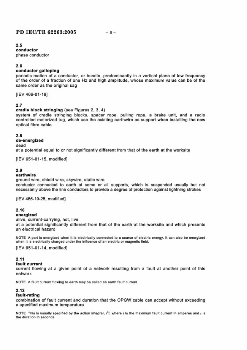
2.5 conductor phase conductor
2.6 conductor galloping
-6-
periodic motion of a conductor. or bundle, predominantly In a vertical plane of low frequency of the order of a fraction of one Hz and high amplitude, whose maximum value can be of the same order as the original sag
[lEV 466-01-1 9[
2.7 cradle block s tringing (see Figures 2, 3, 4) system of cradle stringing blocks, spacer rope, pulling rope, a brake unit, and .a radio controlled motorized tug, which use the existing earthwlre as support when installing the new optical fibre cable
2.8 de1nerglzed dead at a potential equal to or not significantly different from that of the earth at the worksite
[lEV 651-01-1 5, modified]
2.9 earthwlre ground wire, shield wire, skywlre, s tatic wire conductor connect&d to earth at some or all supports, which Is suspended usually but not necessarily above the line conductors to provfde a degree of protection against lightning strokes
(lEV 466-10-25, modified]
2.10 energized alive, current-carrying, hot, live at a potential significantly different from that of the earth at the worksUe and which presents an electrical hazard
NOTE A part Is energtzed \\1\en It Ia elecltlcally conneded to a source or e1ec1t1c energy. 11 can also be energized wt1en Il ls elec«rtcally charged under the lnnuence of an elec«rte ot magnetic field.
[lEV 651-01-14, modified]
2.11 fault current current flowing at a given point of a network resulting from a fault at another point of this network
NOTE A fault currenl flowing to earth may be called an earth faun current
2.12 fault-rating combination of fault current and duration that the OPGW cable can accept without exceeding a specified maximum temperature
NOTE This Is usually speclned by the action Integral, f t, vlhere i i s the maximum raul! currenl ln ampere;a and t is lhe du.rauon In a.econds.

-7-
2.13 Induced cu nre nt cmrent flowing as a result of Induced voltage
NOTE Anwnwanted Induced ctJ rrent along an lnaulal lng surface Ia .a leakage ctJrrent.
2~14 optical attached cable. OPAC ground wlr& wrapped optlc:a~ (GWWOP) cable non~me1:a.ll lc optical fibre ca.ble designed to be wrapped or lashed onto the ex~stlng aarthwlre or phase conductor
NOTE One o1 1h& lollowlmg tllr.ee an acl'lm.enm metliloda l a. used :
- wrapped= .all n lelectJtc {wrap):: using special machinery, a •lgliltwelg l'lt 1lex:lble llon-melall lc opl lcal ftbre· calllte •C81'11 b& wrapped lil&llcally around ellher tiLe ear1hwlre orthe ph8.3& conductor;
- l8.:!11led: non-met al[lc cable:s that ai!'EI ln:stal led longlludlllally a loog&ld& the e~rtli'l\'l1 r&, tile plila-se oondwd or or 0 111
a separate catel!lary (on a pole roul e} and are lhe1d 111 position \~lth a binder or adhealve eord:
- preform anacl'lled= almlls:r to !he lalll'lled cables excspt that 1lhie IN!ithod o1 atlachmenl lnvotvaa. tile use ot special preformed spiral anaehmem dips.
2.15 optical phas.a conductor cable OPPC stranded metaUic cable lncorpora11ng opt ica l flbres wtl lch has the dual performance function of a phase conductor with te~ecommunfic:aUon capabilities
2~16 optical ground wlra cabfa Q1PGW stranded metanlc cable. fincorpora.tlng optical fibre-s which has the dual performance funcHon of a convendonal earthwlre, with telecommunicat ion capabiiiU&s
2.17 optical time domain raftactometetr OTDR Instrument which Is used to measure and lo{;ate point and distributed losses along the length of an optical flbre
2~18 pull section pull setting, s~rlnglng section &action of l ~na whar& tha optical fibre cabh;t fis being pulled Into place
2~19
.sagJglng proeess of pulling the oplilca l fibre cable up to Its final sag whare app l~cable
2.20 sealing en dl assamblly throug1h which OP'ltcal fibres pass pmvldlng suffldent Insulation and voltage whtlstand ca.paclly to maintain system Integrity

PD IECITR 62263:2005
2.21 stringing
-8-
process of pulling pilot ropes, pulling ropes, optical fibre cables, e.arthwlre and conductors over stringing blocks supported on s tructures of overhead lines
2.22 vibration damper device attached to a conductor or an earthwire In order to suppress or minimize vibrations due to wind
[lEV 466-11-16]
3 Understanding the hazard - Basic theory
The protection of personnel from Injury during the process of Installing, or during maintenance of optical flbre cables on overhead lines Is most Important. The personnel at the work sHe shall be protected against induced voltages and currents caused by energized adjacent Jines. Personnel protection can be achieved by property applying adequate protective earthing systems at the work area, by the use of correct work methods and specialized training, and by the use of equipment, which incorporates devices to protect against these types of hazards.
Electrical charges or voUage may appear on an optical fibre cable being installed, or on the other equipment and components such as the ropes Involved in the cable stringing process, due to one or more of the following factors:
a) electromagnetic Induction (I.e., capacitive andfor Inductive coupling) from adjacent energized lines, or when crossing energized lines;
b) accidental contact of the optical fibre cable or ropes being installed, with an existing adjacent energized line:
c) electrostatic charging (I.e., conductive coupling) of the optical fibre cable or ropes by atmospheric conditions or by an adjacent high voltage direct current (HVDC) transmission line;
d) lightning strikes In the vicinity, or a lightning strike to the cable being Installed or other equipment and components such as the ropes involved In the s tringing process.
The hazards caused by lightning strikes, accidental contact with a live conductor, and switching errors are generally understood. However, the hazards caused by Induced voltages and currents are probably less understood and are therefore explained In some detail here. It is Important to note that the basic difference between the hazard caused by Induction, and the other $OUrCe$ given a bove I$ that the Ind uction I$ co nUnuou$ a$ long a$ the $Ource line I$ energized, rather than Instantaneous or transient In the case of lightning or a fault current.
NOTE In the lollovJing examples, lnduCUon Is shown aa occurring on an optical fibre cable; hOw~ver, the same result and hazard v1111 oooor lot otfler components used in the stringing process such as conduCUng (metallic) pulling or pilot ropes. or earthwf res.
3.1 Electric fteld Induction from nearby circuits
There are two common types of Induction problems caused by nearby energized a.c. Jines: electric ffeld and magnetic field. Each has both voltage and current implications.
3.1 .1 Induced voltage
The electric field around an energized conductor produces a voltage on an Isolated and unearthed conducting object nearby (see Figure 5).

-9- PD IEC/TR 62263:2005
The voltage produced depends on the source voltage magnitude and the geometry of the system but not on the length of the parallel between the energized line and the new optical flbre cable being Installed.
If the circuli Is unearthed, the induced voltage may be as much as 30 % of the energized line voltage. This Induced voltage can be calculated, but it Is generally not necessary to do so. If the new optical fibre cable being Installed Is earthed at any point, the charge Is reduced to a much lower s teady state value, depending on the resistance to earth of the earth path.
NOTE tt the nearby nne I& an energized d.c. transmlaalon line, electrostauc charging wt ll result from ion drln aoo can produce even hig:l\er vol tages than If the nearby line was an a.c. Une.
3.1 .2 Induced cunent
With an a.c. system, the energized lines and the earthed conductor being installed act like the plates of a condenser or capacHor, and a charging current flows across the air gap between them (sea Figure 6).
The two following aspects should be considered.
a) A current flows through the temporary earth connection between the optical fibre cable and earth. It Is proportional to the length of parallel between the energized conductor and the cable being Installed. This current may amount to several amperes.
b) If the temporary earth connection becomes defective, Is dislodged, or removed, the capacitive voltage is Immediately re-established. Thus, if a worker Is In fairly solid contact with the system and the only earth connection Is dislodged, the worker can be exposed to a dangerous voltage and current. If the worker attempts to contact the optical flbre cable or connected parts, he wtll receive a aangerous dlscnarge current, followed oy a steadystate current. Thus, the worker shall avoid coming In close proximity to the optical fibre cable or connected parts since the Induced voltage may be high enough to cause arcover. Also, It should be noted that the steady-state capacitive current occurring after the contact may reach a dangerous level.
3.2 Magnetic field Induction from nearby circuits
3.2.1 Induced cunent
In addition to the electric field caused by the voltage of the adjacent energized line, another effect Is caused by the current flowing In the energized line.
The energized, current-carrying conductor and the nearby optical fibre cable being installed may be looked upon as the primary and secondary windings of an air-core transformer.
If the optical fibre cable Is earthed at two places, It acts like the secondary of an air·core transformer, short-circuited through the earth. A circulating current will flow along the cable, through one earth connection, back through the earth and up the other earth connection to complete the loop (see Figure 7a). This Induced current Is proportional to the current In the energized line and Is dependent on the geometry and Impedance of the loop.
If a series of earth connections are applied, a series of loops are formed, each carrying curran! (see Figure 7b).
It would appear that the currents would cancel In the Intermediate earth connections.
PD IECITR 62263:200a -10-
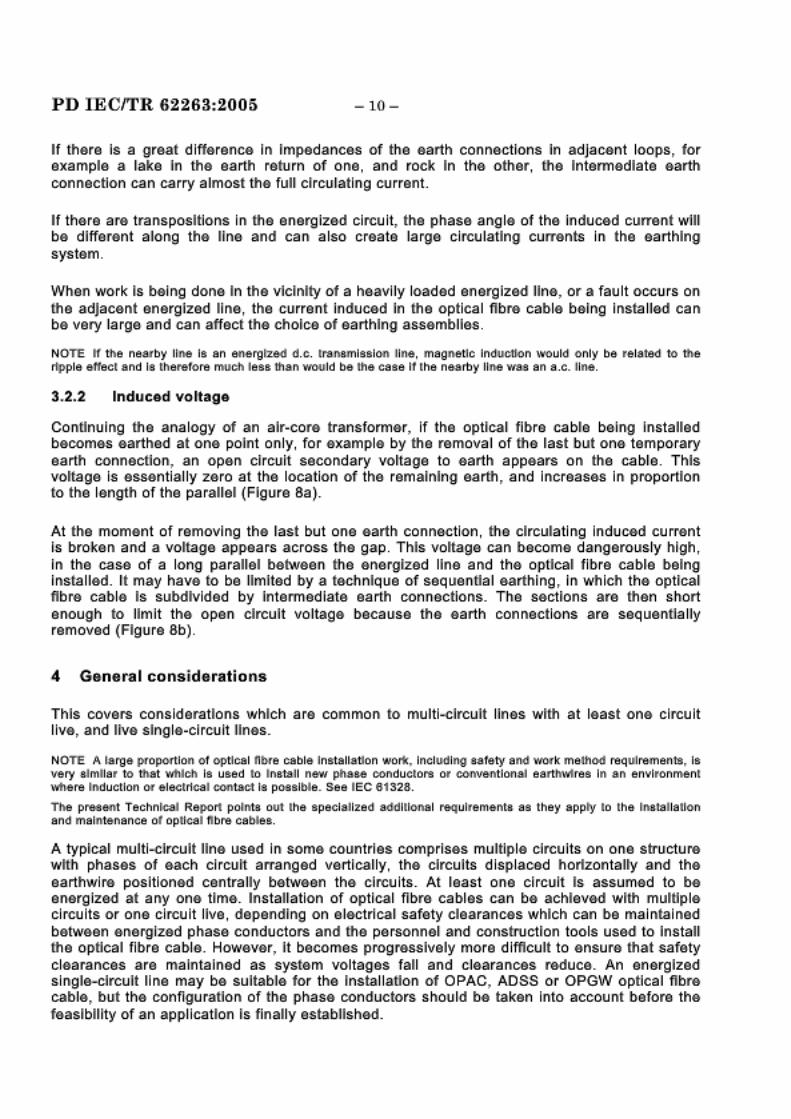
If there Is a great difference In ~mpedances off the earth connections In adjaoont loo[pS, for example, a ~ke In the earth retu rn off one, and rock In the o ther , 1he lntermec:Uate earth connection can ,carry almost the fun drcu~tl1111g cmrent.
If th&re are transpositions In lhe energized circuit, the phase, angle of the, lnduca.d current win b& different along th& nne' and can a I so create large, clrcu latJng currents In the earthing syst.em.
When work k being done In the vicinity of a heavily l oad~ed energ ized line, or a fault oocurs 01111 1he ad)ac&nt energized line,, the ·current lnduc&d In the opt ica l flbre cable be~ng lnsta lle.tl can be very large' and can affect the choioe of earthing assemb lies.
NOTE tf t ile nesrby line IB an en erg~ d.c . Irs l'lllfl'lh~B ioo line , magnetic lnductf.on \WCUid only be· related to the r1p ple· e.1teo~ and Ia tl'lere1ore rmJoll ~esa 11ilalll would be. llile case 11 lhe nearby liRe 'WiiS an a .c. ~ln:e .
3 .2.2 lnduceal voUage
Con11nulng 1he analogy of an alr~core t ransformer, If the ·OpUc.al fib re cable being Installed beoom&S earthed at on& point o1111ly, for example by ~e removal of ftle ~ast but on& temporary earth ~oonnec111on, an op&n circuit secondary voltage to earth appears on the cable. This voHage Is essentially z.er~o at the, location off the remaining ear1.h, and lncreas&S In proportlonr to the lengrth of the pa raUel (Figure 8a )-
At the moment of removing the last but one earth connection, ftle circulating Induced current Is broke,n and a voHage, appears across the gap. This voltage, can become dangerously high, In the ca&e of a long paraUel betweenr the energltzed line and the optical fibre cabfe being Insta lled. ~may have to be limited by a tedhnlque off sequenOal Mrlhlng , In wtllch the optlca~ ftbre cable Is sub-divided by Intermediate, earth connections. The secUons are, 1tl~n short enough to limit th& open d rcult vo ltage because the earth connections are sequen111ally removed (Figure 8b). ·
4 G&ne r.a I co nsid&r.ati o os
lihls covers considerations which are common to multl-drcult lines wHh at least one clrcu l1t live, and lllve slngJie~clr,eult Unes.
NOTE A la rge. proportion o1 optical lime cable. lnBtallatlon wort, Including sa1e.ty and Wfll'k mel l'loo requirements, IB very :similar to that wtJJoll Is uBed tfl l llls.ts11 new pl ta1111!1 ooi!Jduclors or CO'JW&ntlona1 eartln'ilres In a lll envlronmenl Vt'lu!lre Induction or e lecl r1caJ contact Is possible. See IEC 61323.
Tile present TeehnllcaJ Rep ort pol:nt'!l out lhe· spec:la'llzed 841i1111M al requlr>emelllts as they .apply lo lhe lns-'t!ll lal lolll and malntelllanoe ot opl lcal 11bre, oablea.
A typical multi-circuit line used In som& countries oomprlses multip le circuits on one structii.Jre wHh phases of each circuit arranged vertlcamy, the drcults dlsplaoed horlzontalty and the earthwlre positioned centra lly b&tween the circuits. At ~east one circuit Is assumed to be energ ized at any one tim&. lnstanatlon o,f optical fllbre cables can be achieved wlittl multip le circuits or ·one circu it live, depending on electrical safe,ty d earances which can be maintained betw&en energized phase' conductor~ and 1tle personnel and construction tools II.Jsed to lnstan the optical fibre ca bl~e_ However, It becomes progressively more dlfflcLllt to ensii.Jre 1hat saffe,ty clearar11ces are rna lnta lned as system voltag}es fall a1111d c l&ara noes reduce,_ An ener·glzed slngle,..cJrcult line may b& sultabl& for the lnstalla1Jon of OPAC, ADSS. or OPGW opt lca l .flbr-e c.ab l&, but th& oonflgLlrafio,n of the phase conductors should be taken Into account before the feaslbnlty of an applicat ion Is finally established.

-11- PO IECfrR 62263:2005
4.1 Engineering consider ations
4.1.1 General
Helical fi ttings with a reinforcing layer are preferred for maximum optical and mechanical protection of the optical cable. They will ensure that mechanical loads are evenly spr.ead and the cables are not crushed, thereby affecting the optical perfonnance.
Splice closures should be reslstanc to damage, and be located where possible, out of public reach.
Minimum bend radii, as specified by the optical flbre cable manufacturer, should be observed during all installation processes In order to preserve the Integrity of the optical flbres. This w111 dictate the minimum diameters of tensloner bullwheels, stringing blocks, sagging/tensioning devices, and clamps which are to be used.
The optical ftbre cable marnufacturer may require that the sb'fnglng blocks have an elastomer lined sheave. In this case, a stringing block earth connection will be necessary Co provide the required earthing path.
To ensure maximum reliability and avoid cable damage, It Is important to ensure that all fittings chosen are compatib le wfth the optical cable system selected.
The optical fibre cable should be Installed smoothly with no sudden changes In stringing spMd or tAnston. Ma~lmurn stringing sp66d rAtoMM&ndAd by th6 eabiA manufaeturAr should be followed. If the cable manufacturer does not specify a maximum stringing speed, a conservative value Is 40 m/mln.
The tension on the optical fibre cable during stringing should be measured at the tensloner. This tension should not exceed the manufacturer's maximum tension recommendations which are normally 15% of the rultlmate tensile strength of the cable. Some utility specifications require that a s trip chart recorder be Incorporated Into the tensloner such that a printed or electronic record of actual tension on the cable Is provided.
Under certain circumstances, to maintain clearance from energized conductors, It may be necessary to increase the stringing tension above 15% of the ultimate tensile strength of the OPGW fibre optic cable. This increase In stringing tension should be approved by the manufacturer before Installation begins. Also, the length of the woven wire mesh grip may have to be Increased from the typical 1, 7 m up to 3,0 m to accommodate the lncll'ease in stringing tension.
The optical fibre cable sho1Jid be allowed to Initially settle after pulling Info place and before clamping ln. However, this should not exceed 24 h. Typically cable manufacturers require a minimum time for this to be done.
The continuity of all fibres for each reel of optical flbre cable should be checked when the reel arrlves at the work sHe, and before it is Installed on the s tructures. After completion of this test, the cable ends should be re-sealed against moisture entry.
Continuity should also be checked after the optical fibre cable has been Installed on the transmission line to ensure continuity remains.
Continuity should be checked once again after any splices are made.

PD IECITR 62283:2005 -12-
It Is also recommended that the cable be checked for attenuation loss when the repeater section has been completed.
4.1 .2 Specific
The completed system should be capable of working within a specified temp-erature range wtth the optical flbre.s remaining strain-free under heavily loaded conditions, such as wind and Icing.
4.2 Safety Issues
4.2.1 Choosing the correct equipment
For tho cable lndallatfon procou It h~ Important to choo~o Gqufpmont with s;ufRclont capacity Co perform the work to be done. This should ensure a margin of safety beyond the actual requirements of the work.
4.2.2 Pre-work check of equipment
When Installing new optical fibre cable near existing energized circuits where electrical contact or Induction may occur, It Is especially Important that the equipment used such as pullers, tensioners, and lugs be thoroughly checked beforehand by competent trained persons Co ensure they are functioning properly. In particular, braking systems should be checked to ensure correct operation and maximum load holding capabiltty.
The puller and the Censloner should have controls which will allow the operator to preset the maximum line pull or tension which will not be exceeded. This will prevent overstressing of the optical fibre cable as It is being Installed.
Pulling ropes shoul:t be examined for possible dama·1e that may severely reduce their strength. It Is recommended that a sample of synthetic r~es used as pulling or pilot ropes be tested for ultimate strength at least once each year. \Veak or damaged ropes should be replaced.
Where synthetic ropas are used as pulling or pilot ropes, they should not be considered as Insulating. They maj' initially present a high resistance electrical path, but experience has shown that over tlma and with use, the surface of the synthetic rope becomes sufficiently contaminated to be conductive, particularly In wet or hum!d conditions.
It is also Important 10 choose a pulllnQ rope which has low elasticitY or stretch when under load. The rope should also match the Weight per metre of the optical fibre cable or be even lighter so the rope will not sag lower than the optical fibre cable thus ensuring electrical clearance Is maintained.
Where an existing earthwlre Is to be replaced wtth an c·ptical fibre cable, often the existing earthwlre Is used as a pulling rope to pull in the new optical fibre cable. Since the mechanical strength of the existing earthwlre, and particularly the compression joints, may be very questionable, this procedure should require extra caution. It is highly recommended that the existing earthwlre :~e examined beforehand to determine If wire breakage, or other deterioration has occurred. If such significant damage Is detected, the existing earthwlre should not be used as a pulling rope.

-11.3- PD IEC/TR 62263.:2005
It the existing ear1tlwlra Is used as a pulling rope, o.xtra caution Is nudad. The pass~ng of old .earthwlre. ]olnts or sp l lc~ around the buUwheals of a do>Ubl& bu llwhael or multi~groove.
pu ller. can causa sudden failure of the j oints . This failure. normally oecurs wtum the joints are bent and than stra lghtened a number of tl mas as they pass from groove to groove on the. bu llwiha&ls. The exls11ng earthwllre and the· optical f jbre cable may drop, causing damage to the ca bfa or the. II ne. structures, and may cause dangemus elactrl cal contact.
A preferred procedure. Is to cut out the. compression Joint when lit arrives In front of the. puller , and to 1lt a w.ovan wiJre, grip on b-ol'l e.nds ot ltle severed eoarthwlre. This grflp Is passed througlh the puller bulllwhea l\s, and can be removad before the. earthwlr.e Is wound on fue reel winder . Also this problem can be e. lim Iiila ted without cuttln g out t tle compression joln1 by the use of a single V-groove bullwh9<91 puller.
Run nlng ear1tls, ear111 cab les, ear1tl clamps, and strl nglng block .earths should be. checked to ensure they are operating correc11y and have no bmke.n or damaged parts that wou ld ne.gatlvely affeot the desired low res I stance earth path.
4.2.3 Pra-work conference
It Is especially Important where the poss~blllty of the optical fibre cabfe being lnstalloo can become. energized through lnductio·n, or when working n.ear existing e.nergl:zed conductors , that all members of the work crew understand the hazards Involved. The.y should have ttle wor1k procedures and their duties clearly explained lmmoo~at.elly before. wmk begins. They shou ld be .aware of Ole necessity of using the eart.hlng and bonding systems d&seribed tle.reln, and In I E!!!C 81328, and tney should know how to Install and use these earth lng and bondlng1 syst·sms properly_
It the soop& of the job changes , or U ]ob p;9rsonnel changes , work proced ures and dunes slhall be explained once again to all personnel affected.
Be1m.e wonk beg ins , 11le project supervisor should t rav-el 11le work site from pu ller s.lte to tensloner site·. Tnls Is done to ensure that all potential contact points wltn ,existing ener;glzed eq ulpm·ent or conductors ar.e adequately protected from contact wltll tne opUcal fibre cable being Installed by clearance, by Insulating covers or by rider poles and ne1s.
4.2.4 Tra lnad oper.ator.s
The. specialized equipment used In the slrllnglng of opt ical f ibre cable requ ires that operators be ·given s,peclal training beforehand In Its safe, and proper use. Tnls Is partlcula.,ly lm(}ortant wnen they wlm be working o·n projects where maximum .ea rthing pro.cadu!">ss are. requ ired, due to the possibility of the cable or e:qulpment becoming energized.
4.2.5 Com m u nlcatlons.
The. abiiH.y of the equipment oper-ators , supervisory personnel and observers at orltlca l points In the pull section (sudh as at energized llns crossings) to communicate. dearly and quickly wllttl one another Is extremely Important when lnsta~llng optical t lbre cables.

PD IECITR 62 2 6 3:20 0 5 -14 -
ihesa persa nnel sha II each have a rad lo system wltrn a cha.nnel that Is free from a u'lslde signal and nollse Interference, and Is located at their operating position. lnchuded In this communication channel should ~}a the, pulle.r operator . 1tJg tanslonar operator, the supervlsor(s~ and, If applicable, 1tle person following the an1J~lwlst running board as It moves from tower to tower, and persons at Intermediate check points_
Falhi.Jrn of any radio· In the system shall be ca.use for Immediate stoppage, of the pulling operatl on_
l'he radio or telecommunication .system used by tha puller operator and the' tens~oner operator shall be, a portable set with e.arphones and mlcrophona, but with no conductive wire connection between the operator a.nd l!he machine. Such a ronngcOan could create a dangerous electrical path to the oper.ator If electrical contact Is made during stringing and If 1tle operator were to leave the· bonded area with his radio still attached to his person.
lo ensure that there al"ff no undetected problems due to machinery becoming Jfammed or ropes snagged. It Is recommended lJh.at observers are placed at regular lnterv·als along the sac11an so that tlhey have a ·continuous view oftha work baing conducted_ -
4,.2.6 Of!ner .safety requlr·ama,nts
lhe minimum safety clearance' as spadfled in the applicable, local safety ru las shall be maintained at all 11mes_ This Is often most critical at anglelt&rmlnal towers .
l hroug hout 1tle I ns1allatlon process, It the mIn I mum optical fl bre bendIng radii us ·can be maintained, ropes and cables at 1Jlg puller and tenstonar gnds of the pull sQ:cUon srnould be routed 111rougn the body of the tower from the tower p,aak to the t&nsloner or pulfer at ground laval. Equipment shall ba hauled up the centre' of 1he tower, or on a face perpendicular to tne eartlhwlre, or by helicopter, particularly when bo1tl circuits of a double, circuit tower are live. Control of ropes and eq ulpment Is critical In thQ vlcl nlty of any lllwli circuit. Whera one clrcu It can be de~energltzed on a double clreult tower, all wort ls restricted to the de~energlzed side of a II towers_
All tawf!lrs. components and equipment snail be protected from mechanical ave.rloadlng by appraprmat<9 methods ·Of working_ The method of working should ensure that, In the case of a med1anlcal failure of a component tha nacessary restraint Is provided to prevent the optical flbrg cabla moving towards a live circuit.
Emergancy proc9dures shall l}e In place' In case, of unforeseen events which could result In mln~mum safety clearance helng Infringed or personnel being endangered In any other way_
Work should proceed only If weathar conditions permit. WIJnd, humidity, l ~ghtrnlng storrms, and visibility are. all Important cansldera11ans In tills regard.
During Interruption of the work pertod, the optical fibre cable sadlon should be ssoored ~n a safe and appro prtiat& manner .
-15- PD IECITR 62263-:2005
It Is reoommended that water-b locked and .sheathed ropes are used when working near live circuits In order to avoid Induced currents In wet rope'S which can cause Dum lng as they dry ~out. Where synthetic ropes ars u~sd as pullllng or pilot ropes, they shou~d not be cons~dered .as Insu lating. They may ln~tlally present a high resistance elec,trlcal path, but expertenc~e has shown that over Ume, and with use, the surface of the synthetic. rope Decomes sufficiently oontamlnat&d to bt:t conductlvt:t, particularly In wet or humid oondltlon.s.
When working on the Installat ion of optical flbrt:t ca ble which Is close, to a l ln ~e carrying high electrical (oads, or to an adjac9nt llvt:t circuit, cart:t shoii.J id be tak9n to accommodate by means ~o f ~sa rthlngJ ami bondIng the, hfigh Induced CI!J rrt:tnts. and volftage which can occur In the optical flbre cab Is.
In 1tle cas9 of live sing le... or multi-circuit lines, wort can be I!Jnd9rtak9n o~n OPA.C and .AIJSS systems If sufficient electrical .safety dea.ranc9 to the live circuit l.s obta~ned. Work can be undertaken on OPGW .systems wllth the circuit or circuits live If .sufflclernt ele.ctrlcal clearances are ach lev<ed.
For slngle-drci!Jit and mu~tl-clrcult lines which are de-energized, all types of optical flDre cable may be Installed and malntaln<ed as they wou ld be, for dead circuit oondltlon.s dt:tpendlng on th~e positioning of tht:t earthwlr<e(s), but Induction from ad]acernt lllve lines or live lines crossing ths optical fibre circuit may s.tll l be, an Important consideration.
Work on llvt:t lines shall De conducted with ths dt:tlayed auto recloser (DAR) swltcht:td out and It shoi!Jid be tagged with a nom to Indicate that the' DAR Is In fact sw11tched out.
Work on lines which have either one or mort:t circuits. energized shou ld only be undertaken where It Is Lmr<easonabl<e for a.ll circuits to be d~s-energlzed, tor tht:t time period essentia l for carrying out th<e work. The system network management contro l should confirm that fact In wdOng, gllvlng reasons If any network circuit outages would be avallahrs for a short,sr parted and und<er what conditions. - -
4. 3 Earth lng
The, d<egrt:te of t:tarthlng prot&ctlon requlrt:td ·for a gfvt:tn optical ·flbrt:t cable Installation project depends upon ·fbe ~exposure to electdcal hazardls which t:txlst wlllhln the particular work area
~on ltls proj ;Bcct.
When new o pUcal fl Dre ca.ble Is Installed In an area rematt:t trom ener,glzsd lines, or when adjae&nt lines on the same towt:tr ars de-energized. and wllth no 1tlunderstorm acUv~y present, ths minimum ear1tllng requirements, at least. shall be used. These mlnlmi!Jm requirements Include b-onding and earthing of a.ll ~equipment Involved at pi!JII and tension sites. In addition, running earths should be Insta lled on all metallic pulling r~opes, Olfl1 the ~optical fibre, cablle, and ~on the-<Bxlstlng earthwlre (If It Is to De used as a pulling rope}, In front of the pulling and tensioning equ lpme nt. When ml n I mum earthIng requIrements ar9 used, It shouf,d De noted that protection of workt:trs from .step and touch potential does not exist

PD IECITR 62263:2005 -16-
In contrast to thiB' abo·Vft, for a projQet located ~n a con g0sted area ~nvo lvllng exposure to numerous energ l:z.91d parallel lines. or when working adjac£tnt to IB,:xJistlng energl:z.Q;d mnes on ·fhe same tower. or If the project calls for the cross~ng of IB,xlsftng energ ized lines, and If th0re Is a h~gh probab~llty of thundeorstorm activity and advers9 weatheor conditions, then maximum earthIng reoqu I r·emeonts shall be used _
Such maxlmi!Jm earth ing reqi!Jirements ~neii!Jde bonding and eantllng of equ lpm0nt, th e use of running ;earths, !11arth mats at work sites. and slrlng~ng blodk earths on each stringing block. Th9Sa earths and mats sham be sl::z.ftd and d0slgned for a fau lt curr,ent where. direct contact wtlh an ftnergllzed line Is poss~bliB' .
Sizing of the lndlvldi!Ja.l earth cla.mps, eart.h cable'. or earth rods .are mot detailed h0reo, but some. glenera~ gi!Jidem nes can be found In Annex A.
In addiHon to making sure the appropriate swltcheos em th0 line. where the neow optical fibre. cablft ~s beolng lns1:a lloo are opeon and disabled, 91arthlng and other protective measures shall be em pfoyed to ensure ad~Bqllate' and reatSOnable protection to all pers{)n nel. T he best safety pl'6c:.autlorn Is to cons~diB,r all equlpm41rnt. and the optica l fibr41 cable, as tf It could beoomft energ Ized at any 11m eo. Th0' degme of protection provldS~d for a spoclflc project shall be a deoclslon mad41 by thft projed supervlsGr, subject only to the' applicable r!l1gu lations ~n force for that situation, and based on a clear understanding ofthe potential ha::za.rds.
Wihen working In populat0d areas wh9rf!ll onlookers cou ld ~nadvertently wand&r Into work sit& areas. addltllonal measur!l1s for loo~tlng the. work site. such as safety· observers and warnlngJ slgrns. are r~Bqulr''!Bd . Work sites shall b& surrounded wilth ktnce and warnlrng signs prominently posted to alert ·onlookers to the dang~Br.
Where a pull&r, t~ensloner and othtBr assocJated &qu lpment are required for tht9 opUcal flbM cable Installation, a funced equlpot~BnHa l ::zone' or earth mat should be. created (as detalltBd In IEC 61328) to provide electrical pro1eetlon to the p0rsonntBI operatlrng1 the equipment
A running earth should b& used adJacent to both the tens~oner and the puller to guard against the effects of Induced voltages In the earthwlre or cable, during the Installation process (see IEC 61328).
It Is. r~ecommendQ;d that the lnt~Bgrity of the, earth bondlrng betweoen 1tle towftr piBoak and th41 earthwl re be veorlfled b&fore commeonclng work.
Wher-e earth rods are used, the, resistance of the &arth rods shall be &lectrlcally tested (meggtBred ) to ensure the reslstan oe of tht9 &arth rod Is less than .25· fl.
NOTE. tt Is Important to check thai lhe pmtecl loo on a:ny energized l ine wfl lcli'l coul.d oonlact the optical flb.re cable berng lnsl all ed Is deelg ned to clear tile 'fau lt oorr&nt It the Impedance or the eartlh r od Is aB high a:s Z5 n.
If an ~Boarth rod r&slstance of less ·than 25 n can not be obtalnoo, a.n earth mat a"l the work site {see, IEC 61328) shall be used If the. worr1k sltft Is at ground leve l, or an equlpote.ntJial &alif:hlngJ system used In elevated work sl1e!S.
In order to &nsuM that th& d lfferent earth rods at 0ach work sltt9 hav0 the sam& potential, 1tley sha II be bo nde.d tog,eth0r with tum sl::z.ed tBarth clamps and earth cables.

- 1l7- PD IECITR 6226.3.:2005
Wlhen Installing earth rods , .caution should be taken to avoid all underground l.IOIIt les such as existing energized underground electrtc lines, gas, se.wer, and water pipes, communications cables, etc_ A check of underground utlltty sel"'llices In the. area may be. ne8ded before eartlh rod.s are lnst.all&d. ~
5 Optical ground wire (OPGW) ca.b~e
OPGW Is ac::krlowledged as the mos·t .se;cure. o.f the foi!Jr alt·ematlves (see Clai!Jse 1 )•, due to the mechanical protection belrng afforrded to the comnrli!JnlcaftOfl f~br<es by the outer strands ·Of the ground wire. This system can b9 lnstaUsd on new lines and on e.XIlsllng lln<9s durtng1 refurbishment_ ~
5~1 Engineering eonslderatlotns
There are two methods used to Install OIPGW optical fjbre cables:
the oonvenUonal tension me.thod,
the cradle block stringing method.
5~1.1 Con~vantlonall stringing metltod
The OOIIwe.nl onal method of OPGW Installation , I.e. contlni!Jous tension .stringing, Is generally considered the preferab le method If 1he r·equlrsd electrical! dear.ances can bs achieved. It re(!ulres les.s equipment and lns1:a llatlon can be achieved faster.
The. conv&ntlona l tension stringing method will require th& use. of an an11&lwlst running b-oard (sse. Figure 1} for a single layer OFI'GW, and may require an anti-twisting running board for two layer OIPGW, to keep the. OPGW from rotating during Installation. This running b-oard k<Beps the op11cal f•bres straln~fre& during Installation whlcll Is a fundamen1:al feature of th& cable design. This running board should hav<B a flx&d/.solld oonnecUon to 1he OPGW so no relative rota11on between 1he OPGW and the running board tak<es place. If a woven wire mesh grip Is used at the front <Bnd o.f the OIPGW to conne.ct It t·o the running bo·ard, care . .should b& 1:ak&n to ensure thl.s g1rlp has si!Jffici<Bnt capability to withstand the potential ·twiJsl ng force lmparmd from th& OPGW as It Is b&lng pull&d. This running board .should have an appropriate swlv&l at the front end for connection~ to the pu I ling rope,_ Th Is .swlve I wl II not a II ow any twist which occurs In the pulling rope "to be. transferred to th& OPGW. This antl&twlst running board should be designed sucll tha1 It pa.sse.s through th& stringing blocks with minimum effort, especlamy those on line angle· support .stri!Jclures. The running board normally has two weighted tall.s to offse.t the twisting tendency of the OPGW. In some cases, where a J,arger dla meter o.f OIPGW Is being I nsta.lled, It has been found necessary to add a third tall to com plstely offset the. OPGW twist
DI!Jrlng the planning of an OIPGW Installation, to avoid pos.slbl& &lec1J1cal oontact, consideration shoi!Jid -b9 gJiv&n to the dlff&renUal sag be.twe&n the· OPGW and the conductors, partlcularlly when the OPGW and conductors are. operating at dlffe:r<Bnt t.emperati!Jres.
Using the corTQCt stringing block sheave and ten.sloner bullwhe<BI dlamete.r Is Important to protect the OPGW cabl9.
PD 1ECITR 62 2 6 3:.20 o 5 -18-
If the specific stringing block sheave recomme,ndatlons are not avallab~e from the cable manufacturer , a conservative s.heav·e dlame·ter Is 40 times the dlame,ter of the OPGW.
If a .specific tensiDneor bu llwhee l dlame.ter Is not avallabl·e from lhe cable manufacllurer. a oonservaUve bu llwlheel ala meter Is 7'0 tlmeo.s llhe dtiameteor of the' OPGW _
5 .1.2 Cradl& block strlngl ng method
Cradle block sbi'lnglng Is genera~ly used for fttose applications where the required electrical clearance for conventional stringing methods canrnot be achiEwect
Crad~e block meU"'ods of lnstanatlon require unrestricted travel of a radio conlrolled motorlsed fu g aloo g the existing earthwlre. Before an I ns1a lla.tlcn commences. the e:xlsUng ea rthwlre should be. Inspected to ensure that It Is not damaged and lhat thera are no loose ·Or damaged wires_ 111' any damage 1:o the .earthwi'lre, Is found, U shoi!J' d be repaired before th.e Installation commences, or consideration shoi!J id be given to no·t using It as a support member for the cr.ad le blocks_
l'here are two cradle block .stringing me'fhods I!JSBd, d·eperndlng on the proJect being worked on_
Where' n&w OIPGW ~ rep lacing exlstl ng .earthwlre, and Is to be I nsta lied for a number of s paM, the m uiU~spa n crad!e bl'ock system Is norrmally used _
Where, an e~:x1stilng OPGW Is to be replaced In one sparn only di!Je to damage, the sing le span crad le block system tis normally used.
5 .. 1.2.1 Tha multi-span cradle blaock .system
'fhe forces mqi!Jired to pu ll and maintain sag In the new OPGW o¥er many .spans- up to 5 km, require that a larger motorized tug, a pu ller and a ternsloner be used during the Installation of 1tle n.ew OPGW_ TensloM used during the, cradle block str~nglng lnstaUatlon process are however low compare-d to thra norma~ h1stamatilon of phaSts conductor and accurate rontro~ Is required _ Puller and tensloner equipment used for tension s.trlng lng of phase conductors will not genera lly offer the fl ne control r.equ I r·8d at the. few levels of te nslon which therefore, may require specifically d.eslgned .equipment glv~ng excellen-t low tension contro~ of llnepu ll and speed. Gen.era l requlr.8meonts for pullers and te,nsloner.s are d8scrloed In IEC 61328.
l'he. lower tens~ons used for pi!Jmng lh8 earthwlre and the. OPGW In crad le. bloo'k strlng~ng reduce 1tl.e likelihood of faUurft, of the. pulling rope.. the connedors and the earthwlr8 .. However, because the circuit or clrcu Its on the line be~ng worked on are I live and road and ra II crossings are not usually scaffolded. any fa llure of the e:xJistlng earthwlre I the OPGW' or the' pu I ling or mnslonlng sysmm could potentially have serious consequences_ Hfgh lnt·egtrity connections should be used betwe,-sn th8 pu lling rope. and the existing earthwlre, or to connect to the OPGW_
Since It Is dlffici!Jit to dete.rmlne the condition o1f ttl s pulling rop-e. the nominal breaking load of 1tle pu iUngJ rope shou ld be rate.d at feast 10 times the eMpected puUing force when I!Jsed In the cr.ad le block method. 'l'he rope shou ld De lnspeded regularly_
- 19- PD IECITR 62263:2005
Th& mulitl~span tug must have 1he tractlv9 capabi lity to Install U'l9 pulling rope and cradle blocks over many spans up· to 5· km.
As part of the cradle block stringing procedul'!e, It tis necessary to· transf9r the tug around tll'l9 tower p&ak from on9 span to the next. To secure ·ltJe tug during transfer, tll'l9 tug should be ftrst attached to th& tower p9ak by a safety tether, before lmlng It from tll'l9 Installed span Into the next span.
5.1.2.2 The s ingle spain cradle lb ~ock sy.sta m
Where. the n9w OPGW ~ to be, lnstamed In one .span only as a rgpiJacement for the exmstlng damagied OPGW, the force required to pull the cradlle blocks and pulling rope Is qLdte small and ca.n be accomplished by using a battary power&d single span lug.
Removal of the· damaged OPGW and lnsl:alllng of fua new OPGW can be acoompllsll'l9d with a .small winch, or even til:y hand.
ll should be noted tll'lat th Is system can b9 us9d to Install new 0 PGW to r9 pl!ace exmstlng eartll'lwlre In more than one span . but doing so one span at a tlmg,_ It Is however not as cost effectlv·& as usIng 1h a multi-span cradl9• bloc!k S:!Jtstem.
5.2 I nsta~ latlon p roceduros
5.2.1 •Conva ntlonal strl ng mng meth·c:td
Tens I on s1ringlng tach ntiques, as descrl bed In I EC 61.328 can be used to Install tll'le 0 PGW. It Is recommended that fullly hydraulic systems on the· pum.er, tenslonar and ra91 stands b& used. If sl.lfflclent clearance from existing live clrculits on the structure cannot be obtained, a circu it outag,e may have. to be obtained.
5.2.2 Mult,l~.span cradle block string ing method
T ecll'ln lques exist whmch allow replace men1 of th& existing 9arftlrWira without switching out the power drcuU or circuits on the· structure. or on any lower voltage circuits crosslfllg underneath.
One such scheme mak9s use of th9· cradle block s1rlnglng system for multi~span lnstallaUon of OPGW (g,ee Figures 2. 3, 9, 10 an1d 11). lhls Is a S!Jtstem consisting of a puller, a tens~oner,
an earthwi!'J9 taka up stand, and an OPGW l9·t off stand. This syst9m also Includes cradle strilnglng blo-cks, spacer rope, pulling rofle, a brak8 unlit, a.nd a mo~torfrz.ed lug, alii of wll'llcll'l use the existIng ea rthwlre a.s support when I nsta I ling th9r new optlca I flbre ca ole.
Th& advantages of using the cradle' block syst9m are that clr,cult outages are not necessary, and full-fa ulf cllJrrent r.ated, low~reslstance. earth contJJn ullty Is ma lnta I flied th rollJgJhout the operation. The need to prot.ect roads. rai lways. low voltag& lines and other obstrucUons Is mln~m lsed.
In ltla~ly th8· sag of th9• 9Xlstlng earthwl re Is measured wfllch enables the sagging tension of the OIPGW to be calcu lat8d and matched to· the axlsUng earttlwlre. Tll'l9 9XIstlng earthwlr-a Is th,en transferred to temporary anchor points on th& towrar, ensuring that the· con1lfnulity of earth bonding Is maintained. All cable block lnstallaUon equipment Is raised wlfhln the body of the .structure .

PD mcrrR 62 2 s a.:2o o 5 -20-
In a typical mi!J itl-span cradle block str~nglng procedure, 1tla motorl:z.ed tug UJnll ,(seoe Figure 9) Is used to pull two ropes across the span to the next to~wer. The flrs1: rope Is used as a pulling rope for 1he OPGW. whi le, the second, a spacer rope'. Is also attached to the tug unU to a.llow crad le blocks to be pulled oi!Jt along ·fh,e existi ng earthwlr9. The cradle, block (s-ea Figure, 10) has a pu~l ey In each of four corners and an opening gate on each slds. One of the top p1UIIeys. of the cradle block runs along the existing earthwlre and the bottom pulley supports the pu I ling rope,_ - ·
The cradle blocks are clipped onto the spacer rope at approximately 10 m Interva ls as ths motor ized tug progresses acmss 111e span. The exact spacln g Is de term In ad by ensuring that, If the cradle blocks move towards each other due to a loss ot contml of the spacer r~ope durtng Insta llation , the, loops formed by the ropes do not Infringe the e~edrica l safety dearance required.
The pulling rope Is Installed as a continuous l!anglh over the pull section of earthwlre to be replaced , wlllh stringIng blocks to carry It through the lntennad late towers. The pull section length wUI depend on the line roi!Jte, but lengths of 3 km to 5 km are most practical to hand le.
Once the pu lling rope has lleen Installed over the pum se.ctlon, It Is used to piUII In the new OPGW. at a low tension, using a puller located at 111a puller snd of the section. The OPGW Is tensioned during lnstalla1Jon by a tensloner located a1: tlh.a tensloner end of the secUon. and 111an sagg'rad , dipped to Its anc!hors, and bonded electrically to every tower, llhus ma~nta~nlngJ
111a earth conti nuity. The 1:ensfoner ·end of 111e old aarthwlre Is then connected to a light pulling rope, and whi le the old earthwlre ~ being pulled througJh th{IJ cradle blfocks by the puller, ft Is 1:enslonsd out by tlh.a tensloner IIJslng a light pulmng rope to provld·e back ~enslon .
DIUrlng flnal operation tlh.a end of the light pulling rope Is connected to a brake unit (see Figure 11) which Is pulled along the' OPGW and this blrake, unit provides back tension to maintain cradfa bllock spacing. The crad le blocks am recovered from the OIPGW at each tow0r as the lfght pulling roi)a Is baing wound up at tlh.a p1UIIar .
5,..2.3 Single span aadla block stringing method
The cradle bfock stringing system ~s also used for single span Installation of OIPGW to replace an ex~Ung damaged OPGW (see F~gur~es 4, 11, 12 and 13). This Is a system consisting of a radio controlled sing le span battery powered tug , a hydraulnc braked OPGW let off stand, p~us crad le stringing blocks, spacer rope, p1UIIIng rope, and a blrake unit, all of wh~ch IIJse, the axlstJngJ damaged OIPGW as siUpport when Installing the new OPGW In a single span.
Many of the lnstamatlon procedures are the sam a as described for the multi-span crad Is block system.
5,.3 Safety ~sues
Thera are considerable benefllts wh lett will accrue from the lm proved safety of crad le block s1rlngl ng. This procedure uses greaUy redu oed pu ll ~ng tensions. the OIPGW and the exlstlngJ aarttlwlre are supported at regular Intervals and the, earth continullty Is fu lly fallJ it~rated. Thus-, both llhe risk and the consequences of live line contact are red ucad _
-21- PO IEC/TR 62263:2005
5.4 Earthing
The cradle block Installation procedure can provide a fully fault-rated earth connection at all times, if properly Implemented. In order to achieve this, It Is necessary to provide two earth connections at each tower such that the new OPGW and old e.arthwlre can both be attached simultaneously. It Is very Important that the new OPGW and the existing earthwlre are properly bonded at each tower before the existing earthwlre Is removed. This may involve modifying or replacing the fi ttings for the existing earthwfre before pulling In the new OPGW.
6 Optical phase conductor (OPPC) cable
OPPC Is a stranded metallic cable Incorporating optical fibres and Is specifically designed to be used as a phase conductor as well as having telecommunications capabilities. The mechanical and electrical characteristics of OPPC are matched Co those of the other conductors in the circuit. While the fittings for this type of conductor are similar to those used wHh OPGW, special phase-to-earth arrangements are required. An Insulator assembly is used to allow the optical fibres to b& taken from lin& voltage to earth potential at terminations. The optical flbres are fully protected and a sealing end system prevents water Ingress at the point where the optical fibres are separated from the conductor. To daCe, the use of OPPC has been limited to dlsb'tbutfon voltages within some countries, due to limitations Imposed by the special phase-to-earth .arrangements and therefore is not covered In greater detail In this technical report.
7 Optical attached cable (OPAC)
OPAC cable Is a non-metallic fibre optic cable lashed or .attached to an existing earthwlre or a phase conductor.
OPAC cable systems (see Figure 14) have been Installed on existing earthwlres and also on conductors at lower system voltages, where s imilar phase Co earth optical arrangements to OPPC will b& needed. The techniques to allow Installation on earthwlres without a power system outage have been available for some time and OPAC cable has been widely selected for post-fit applications.
Helical wrap OPAC cable Is designed to b& helically wrapped around the existing conductor or existing earthwlre.
Lashed OPAC cable Is designed to be placed longitudinally beside the host existing conductor or existing earthwlre, and a tap& or tapes are wrapped around the pair to hold the lashed optical fibre cable In place.
Preform actached cable Is similar to the lashed cables except that the method of attachment Involves the us& of special preformed spiral attachment clips.
7.1 Engineering considerations
Normally, helical wrapping or lashing Is carried out on existing earthwlres, but on system voltages below 150 kV, conductors of a de-energized clrcutt may be helically wrapped or lashed. The Installation requires unrestric ted travel of the tug and wrapping/lashing machine along the existing earthwire or conductor, since any loose strands could unravel and foul the tug or wrapping/lashing machine as they pass (see Figure 15). Therefore, prior to installation, It is recommended that the existing earthwfre or conductor Is Inspected and any damage, such

PD IECITR 62263:2.00~ -22-
as loose strands, Is repaired be,fore lnslalla1Jon commenc·es. The normal recovery procedure cannot be, used where a tug or wrapping machine Is entang led wllth broken earthwlre, or conduc:lor strands. In this situation, a sing le-circuit outagQ shou~d be .arranged If necessary and a crane used to e.ffQct the r&oovary.
DataUad d~eslgn of the, tug .and wrapping/lashing machine shou ld b-e to a high standard to an sura they cannot fan from fhe earthwlre/conductor by using gates that fully close around the aarthwlre/conductor. Removable' parts of the tug and wr.applng/lash~ng machine, such as cou nter~ba lance we~g hls and cabl-e drums. should be secured to 1tle main body of the machine using fixings with locking p~ns to provide a h igh de:grea of Integrity.
lo ensura that safety clearance Is ma~nta~nQd, the equlpmant rop&S shoul1d ba care,fully controllad during llftlng1 to ensure, that ltay cannot blow out Into the condudors. lFhls can be b&St ach~e,yed by l ffi:l ng a II the e,-qu lpment Inside. thQ towar body llf there Is suftldent space,_ lhe other mathod of mftlng Is om the lower face perpendicular to the line_ Wh-en using th~s method, control slings shoulld be used to rna lntaln the' rope and ;a.qu lpme nt on ttl e tower ce,nlr& I Ina.
Whan machinery Is baing moved around lha tower peak. It shou~d be tetherad to the tower to prevent It from faUing If mishandled_
lhe success of the wrapping/lashing technique, Is critically dependant on 1he Installed tension of the, op6cal fibre cable, since, once tension Is lost, It cannot be restored and l&ose loops. wllll form. Adequate tension Is requ I r&d to ensure, that, under all environ manta I condHio ns, the wra ppe.d/lashad cabl'e remal ns tight to the exlstlng earth wire or conductor. The wrapplngftashlng of the cable .around the earthwlra or condudor Is to ba undertake,n lrn a controlled mannar at constant tension , speed, and lay leng1ih. to avoid loops forming at .a la ter stage. The Wg and wrapping/lashing machine design should ensure lhat. while It Is stationary. 111 e ca bla or la~hlng tension can be maintained for a pro longed pe rlod ..
7,.2 I n.sta nation p rncadures
OPAC ca bias ara cost effective when they are Installed onto an axlstlng ear1tlwl re or conductor wh~ch Is Judged to have suffktiant remaining s~rvlceable UfQ. No heavy Qqulpment or vehicles .are, n~eeded , lrnstaUatlon Is quick and requl ras no earthing proteetlon. OPAC cables are especially suited to, e~:xllsllng lines where Induced vo ltage gradients prevent 'the Installation of selfasupportlng a~erllal cables such as OPGW. OPAC cab~as may be the only viab le solutllon where ground claarances or 'lower loading prevQnt the use of ADSS cables and difficult terrain orr limited access may pre,v9nt tlhe use of altemat lvGJ syst~Bms.
OPAC cable, Is Installed on an earthwlre or a deaenerglzQd conductor with speclall y dave loped ma.chlnery normally provided by the cabiQ supplier and matched to the ~cable to be lnstall·ed. With an Installation on the ~earthwlre, llhe clrcullts can r~emaln live. depe.nd~ng on local worrklngJ regulations. Obvious ly, lnstalla1Jon onto conductors Is not feasible for a double,-clrc:ult mne wlth1 both cii'Clllts e.nargl:z.ed. Nor can OPAC cables be wrapped or lash"Bd onto bundled conductors. l he Installation machinery consists of a counterabalanced wrapping/lashing maclllne pulled by a radio-controlled motorlsed tug, or pulled manually from the ground for lower OPAC cables.
-23- PD IEC/TR 62263:2005
Machines have also· been developed to remove wrapped cable and 1ft Is recommended that these be, considered as an I nlegral part of the wrapping system_
Warning devices, such as alrcra.ft warning spheres. bird f llg1ht dlv&rters and vibration dampers ate. , should be remov~d lmmoolataty prior to Installation ·of the OPAC cable. At the designated .start point (known as a spinning tower) the tower Is rilggad to ra~se the Installation machinery to the approprlat& posiUon on the lower. The first Items to be raised and placoo onto t ile axlsUng earthwlre or condii.Jctor are the motorlsed tugs_ OPAC wrapped cab~a Is normalty supplied on drums, wound back to back as a cassette, wh lch ensums maxi mlllm dIstance b&tw&en splice'S. However , In soma clrcumstanc&S, a single drum may be ~JSJed. The cab le drums are the,n lnstalfad on the wrapping! machine, t ile Wihole assembty raised up the tower, transferred onto 1tla ·existing earthwlre or conduotor and coupled to the lugs_
Wllan the wrapping/lashing machine and tug are posltlloned on ltle conductor ·or earthwlre, .safe1.y lodks which prevenU ha machines from leaving the conductor, are engaged. The optical flbre cable, which nas be~n designed for earthwlr& or conductor lnstaUatlons. Is secured around the tower and on both span ·ends before the wrapp~ngJilasnlng Installation starts. This Is done at every tower by Lllslng a cable· clamp and a mechardcal bridging device arolllnd the tower. Similar devices are used to bridge conductor tlttlngs sucll as vibration dampers. Wrapping or lashing ·ltJen proceeds In elither one or both directions from the tower.
from ttle spinning tower, one span ~s Lllsually complefe;d before starting tne other which ansu res that the l'!e will b-e no lnte ractlon between the rad lo control units ot each lug. A hellcopmr can also be used to tow the macnlne In ·certain applications. The' use of helicopters to move machln&S and p-eople from structure 1o structure, .speeds up the Installation s.lgnlflcanUy _
On comple1Jon of a span, llt Is essen·Ual 'lo secur~e tne optical cable to 1ha conductor to pr~vent loss of tension during transfer of tne machinery to the next span_ Du~ to Its walglht. the maclhlnery Is transferred around the tower using a smaU Jib and hand winch. ·
When the wrapping/lashing machine reaches a designated splice point or terminal towll1lir, tne remaining ca.ble Is urrwoun·d from the, drum . The cable Is then pass&d throi!Jgh a condllllt wtllch had previously been s9:curad down the tower leg_
7. 3 Sahdy las ues
The wrapplngilashlng machln&ry shou ld oontrol the cabta slllch tnat, should a faiiii.Jre occur . long1 loops ot cable cannot form, possibly Infringing ltl.a safety clearance_ 'lhls Is particu larity relevant to cable r&moval machines.
Before an ~nstalla1Jon commences, the· ·condition of th& axmsUng aartnwlm or conductor and fittings .should be assessed to e~nsure that tney can safely suppo-rt the load of the tug, and the wrapplnglllash I ng machine, a full paylo·ad of cable and racove ry equ lpme nt wlhlch1 wi ll be used If a breakdown occurs_ Adequate factors of .safety shoutd be allow,ed when considering the load on the ear1tlwlre or conductor .

PD IECITR 62 2 6 3:.20 0 5 - 24L-
The approval process o.f a wrapping/lashing! sy.stem should Include a fu ll risk anallys~s of the machinery and procedures to ensure that It ~s safe for use under lllve line condiUons. ihera should De an appropriate emergency plan wllthln the procedures wh~ch adequateny descrllbas 1tle actions to De takran If, during lnstallat~on , there Is a danger of ·ltle safety clearance lbelng Infringed.
Motor lsed tugs .should be equ~ppsd with an emargsncy stop facility to allow l~na cr.sws to ha.lt 1tla ti!Jg at the span and If r.ad lo co n1rol Is fost. ·
8 All dielectric seW supporting (ADSS) ,cable
AD,SS cables are non~mstalllc optical fibre cab l&s which are physlcallly and operationa lly separate from ths conductors. Thra cables are selif~supporUng on spans I!JP to 1 km and have 11'1 e strength and reslltience to withstand the· most sev,sre climates. ADSS ca Dl e has many of 1tla advantages of OPAC caDis with the added benefit of being lndepend.snt of the aarthwlre and the conductors. Howeveor, there Is concern that electrical degradation may sometlmas occur on these ca Diles In hi ghar voltag'a environments, typlcallly o,n lin as with a system voltage above 150 kV. Heavily poUI!Jtad envlronmants can create full'ther problems below this system voltage ..
8 .• 1 Engineering eonslder.atlo~ns
All dle,lectll'lc cables.. part leu larly when lnstaUed on Urnes wHh phasa voltages g raater than 110 kV, are prone to s.he.altl degradation. ~n some clrci!Jmstanoes, deg1radatlon may be mitigated by f:lhe use of special shBath~ng compounds, specia lly designed fittings and by pladng the cable betweern the phases where the space potential Is a minimum. lihe cab le suppmerfllnstalfler. togeth,er with the utUity, should asse.ss the voltag•e stress applicable to the particular llnte. The supplier sh ould pro~de evidence of t!he withstand performance of the cable· sy.stem.
There are a variety of computer models whfich Illustrate the lrave~ of capaeltlvely Induced voltage. on thra s urfa oe of an AJDSS cable. Space. potentia~ plots of doub le--c:lrcu It lines witt! alternate. phasing show a null point at the diagonal lnters~B<etlon of H1e bottom two phases from each circuit. Selecting a cable si!Jpport point In ti'lls region will ensure that, when both clr~eults are. Uve, degradation of the cable sheath wi ll be minim lsed or erad lcate,tl. 'There Is aliso a sl ml lar nu II ptll~nt between the phases of the top two cross arms, lh owever this posiHon on ti'le tower lis not advantageous and will give rise to Increased bending moment:s on ti'le tower. Any slgnUicant periods of slng l e,~clrcu lt working will reduce any phas.e canoe~llng benefits, and so 1tl ls sltuaUon must be considered In the rilsk assessment.
Certain phase arrangemranls do not provide a null point. However, 1tle computer models are able to Indicate tha. most advantageous larndlng point for reduced Induced V·oltaga. leve ls_
When ti'le opt I mi!Jm cable support pol nt has b~B<en chosen. I nsta llatlon beg1l ns with the, fitting of 1tla attachment points and any necassary reinforcing steelwork 'lo each of the· towers al!ong 1tle sec:tfon . The drilling of steel tower members to provide a cable support point Is to be avoided and this shoi!Jid only be carried oLJt wi'len absolutely necessary.

-25- PD IECJTR, 62263:2005
The. design ·Of the puller and the tensloner should allow fine control to ensure 1hat the puiUng force Is always maintained within a reasonable margin. The puller and the tensloner shou ld Incorporate safety systems and redundancy In critical components to ensure 1tlat the rope and AD.SS cable are ne.ver ovar~pumsd and that tension lls maintained llf ~er~ ~s a failure of the machilnerry, thi!Js preventing the ADSS cable c lashing wllth lllve circuits.
The attae!hme nt of 1tle puUI ng rope to the' ADSS cable should be via a h~g h Integrity c:onnsctllon and a swive l. Tlle pu iUng attachment should be S;Q;cured to 1he strengtlh member of the AD SS cable.. If the pllJIUng attachm'Bnt Is to be flb!:sd to the s~rength mem bar with an adhesive, this Is best carried out nmd9r factory conditions. The cable Is th9n supplied wltlh the pu I ling a.ttachment f itted.
A slgnUicant factor In de·termlnlngJ clash ing conditions Is the. weight of llhe ADSS cabfe relative to· the conductor. Tihs ADSS cable lls usually much mghter and will tend to blow out furttler than the conductor. For la.terati wind condltlorns. the b•ow~out for the. AOSS cable can be caticulat·sd. However. the. s ltuaUon Is more complex for long ltud I nal wind cond ltl ons. Wlrnd along the line routs will tend to shift the cable sag towards the leeward tow&r and this effect will be greater for ll.ghter ADSS cables on long spans. llf the ADSS cable. Is .above , or level witt! a co1nductor. this effect malkes tit difficult to calculate the clearances and ensure, that clash~ng Is avoided. Where .suffl elent ground clearance eJdsts. a possible so11utlon Is to attach ths ADSS cable below ~a lowest oond uctor. ADSS cable, has a rela11valy h lg1h str,engiO'I to weight ratio. therefore the sag Is ve.ry sma ll, which helps to maintain ltle mld~span clearance.
Varloi!Js computer mo-dels exist to show the sag p;Qrformancs arnd relatllve movemsnts of different cab les under a range of climatic cond ltlons.
8.2 I nstallla.tlon p rocaduras
A prime oonce~rn during Instal lation should be to preserve, the Integrity of lhe cab le shsath. All dlele.ctrlc. cables shou ld be Installed using the tenslorn s1rlnglng method (s;Q;S IEC 61328) , thus ensuring that the cable is held high enough be,twean structures so· It Is not snagged or abraded along the gr-ound. Tlhe pulling rope' Is raised lrn a oontrolnsd manne.r so tlhat It cannot blow Into the phase, before It Is fi!JIIy tensioned. Ad·squats tension shou ld be ma.l ma.lned at all times such that the pu lllng rope and ca b~e are pulled through tower to lower. keepIng them well clear ofthe conductors and oth&r hazards along the route.
Control of the pmot rope and the pulling rope Is essential as they are raised and brought up to te,nslon. Traditiona lly this has been done by having llrnes men at mld~span using a control rope to contain blow~oo1 until the requlr·ed pulling fore& lhas bee.n established. The linesman tlhsn s lld·es the corntrol rope alan g the ADSS to the. tower and 1he rope lls remo·ved. A mors reU.able way of contro iUrng the, pull ing rope Is to I!Jse tenslo1nlng weights at th9 span ends. It Is recommended that groundf..level protection Is provided. as re_qulred, over obstacles si!Jch as low voltage lines, roads and ralllway lines.
Using the corre-Ct strlng~ng blloc:k shsave. and tenslloner bullwheel dlam&ter Is Important lo protect the ADSS cable.
If the specH~c stringing b lock sh&ave recommendations are not avallab~s from the cable manufacturer , a c:onse.rva11ve sheave diameter Is 30 times the, diameter of 1tle ADSS cable.
PD IECITR 62 263:200 s -26-
If a speclf~c 1:ensloner bullwtlee l dlame.u!lr Is no·t .avaUalble from the cable manufactu rer. a conservative bu llwheel dla meter Is 35 t imes 1he diameter of the A[)SS ca ofe.
Installation and maintenance may be carried out. subJect to corl'!ect safaty pro.cedures, wlthoi!Jt lntellference wUh tne power system. In this respect, self-supporting cables offer a minimal M&an Tl me, to Rep a lr {MTTR) .
The basic principles and techn iques used In the lnstallatlon ·ot these. cables ars very slmUar to 1hose used In the. Installation of ths oornd uctors. Conventional tension s1rtnglng tachnlques are adopted whsre.ver posslofs utilising .standard Installation machinery and accessorfss, although In some ca.sas. specla I mach~ne ry may bs nesdad. Then~ fa re It Is Important to follow the advice of the cab le manufacturer In all asp-ects ofl tne Insta llat ion process.
8*3 Safety k sues
A[)SS cable hlas usually been strung at bottom cross arm level with cl rou Its live'. sm pnaslslngr Its ~ndepsndence from the power system. T he procedure ror stringing with one circuit live. on a mu ltl~clrcu lt system may b-s mars hazardous because of hfgher lnduc·ed vo~tag&s on the cable shea1tl.
When tension stringing ~nstalnatlorn of the optical fibre, cable ~s used, U Is reoommendsd that Ule pullll ng ropes be made of new polyester or poiYPropyle ne materia I, to p 1'19V9nt eltner me.cihan lea I or optical damage to the caMe. At tne highest system voltages, 1he I!Jse of waterblocked arnd sneathed ropes Is recommended lo p r·event el ectrlcal degradation. Where syn1tlstlc ropas ara UJSad as puUing or pilot ropes, they snould not oe considered as Insulati ng. They may· ~n ltla llly present a h~g h- resistance elactrlcal pa1tl , but experience has shown thi!t ove r t ime and with use, the surface of 1hs syntna11c rope becomes si!Jfflclently contaminated to be conductive, partlou larlry In wst or hum~d .c.orndltlons.
It Is a~so Important to cnoose a. pullIng rope. whtich has low elasticity or stretch whan under I oad. lhe rope .should also m ateh the we lg ht per metre of the optlca I fib re ca b~e ·Or be even llghtsr so the rope. will not sag lowsr tnan 1he opt lea I f ibre cable, thus ensurlngr electrical cleara nee Is ma lnta lned.
8 .A Earthing
Although ADSS cables are manufactured from Ins ulating material, thel'ie ~ still a posslbllllty 1hat faa kage curre,nts will occur. Therefore, as with meta llic conductors , a running eall1h shoulld also be· employed on the ADSS ca bl e adJ~cent to both the tan.sloner and '1t1s puller to ensure that any ~nd uced volltages or leakage currents do not present a hazard to tne operators.
Tem porary ea.rth lng clamps should be Installed on the fittings at towers during strlnglrng to pre.vent any l&akagre current wn len cou ld oe harmfu~ to personne~. partlcunarty In wet . h umld anti/or polluted oondiUons .
-27- PD IECITR 62263:2005
9 Ma intenanea
Malnlenanoe of the optical caole systems Is essent ial to ensui"Q that communication Is uninterrupted _ Work on ·mhe power system should not Interfere with the' opera11on of the optical c:.ab le system_ This applies to aU voltage ne,tworks up· to and lnc:'ludlngl 400 kV. Maintenance fa lls Into two main c:.ategorl&s~ rout ine maintenance and correc,tlve maintenance as a result of fa I lura.
The following recommendations are applicable to a ll four op11cal flora ·cable systems, that Is : OPGW cable, OIPAC c:.ab le. ADSS caole and OPIPC caole, and ar~ all also dependent on natlonallilocal leg islation and the overhead line company· poUcy_
9 .• 1 Safety llsroues
RouOne r9!placement of damaged fltHngs and splice closures shou ld on ly be' undertaken with 11'1e clrcult(s) ·energized If the comprehensive risk analysis that has been carried out on safety Issues Indicates that such operation can be performed safely. This an<alysls shou ld Include earth ing, Infringement ot working clearances and training of line, personnel on similar systems. The rl!sks and ha.zards consldefQtl should Include Items such as the nature of the defect and Its likelihood of premature fa ilure, earltl bonding. contact w ith &nerglze d conductors, danger to line personnel and the general pub lic, swlftchlng out of th& DAR, access to towers and security of communications and power systems during repairs_
Where r&pa Irs af(lo requIred on an OIPGW, OPAC or OPPC somewh&re In mid span, these' can be accomp lished using llv~e line working procedures, by suspending linesmen In a ba.sket from a hellooptar. R~epalrs from the to.war can be accomplished on OPGW. OPPC, OPAC and AIJ.SS by using helical or other r~epalr t lttlngs . temporary sllpo.ver heat shrinkable, sl·eeves , two~part crimped repair sllacwes or an approved sheath welding systam, as applica ble. Trials have shoWfl that It Is possible to use a standard repair s~ee,ve under wrapped cable applied by uslrng a hyd raullc crimpIng tool_
AD·SS cable should be repaired oy lowering ot the, ca bf.e, usln1g similar te.dhnlques as for Insta llation _ It Is a lso recommended that suosequent r~epalr be carried out as described abow.
Seriously damaged OPGW or OPPC and OPAC cabl& shourd be replaced. As a temporary measure. e ither a SQ;cUon of ground deplo·ye.d cable, or se lf~supportlng caore should be' used unrtll a permanent r&placement c:.an safely be Installed. If a prior risk analysis a llows normal Installation proced ures, the temporary link should oe Installed with clrcult(s) energized_
Where mechanical damage h:as oocurr,ed only to the sheath of OPAC or ADSS ,cables , a repair using a heat shrink or other sl8oeve to restor& the lnteg1rlty of the c:.ab le may oe suitable. If heat shrink .sl&eves am used, a suitable heat shle~d should l:te employed ·to prot&c:t th& cable du rl ng the process_
A rontroll,ed hand~over betwe.111n the operator and repairer Is recommended 1o ansur,e that no opt ical safety hazard exists to the repair personnel. Before ·commencing a repair to lndlvBdual fibres. It Is recommended ftlat a fibre ld&ntlfler be used to ensure that the. fibre Is unlit.

PD lECITR 62 26 3:20 0 s -28-
9~2 ltoutlna maintenance periods
All overhead mne' syste,ms are~ survey~ed at regular lnterva.ls, l{liWler by ground pa1rol or hellcopt&r. Thlls allows remote ld ~entlflcadon of any obvious problems on the electrical power syst,em with all c.lrcult(s) ~energized . During this survey. the optical cable; system should be routinely I nspe.c.ted ~n the same man ne~r.
9*3 metal led lnspactlon
RouOne maintenance should consist ot visual Inspections of 1bs cable and fittings during normal line patrols.
A more thorough inspect~on of the power network Is normally carried out on sacll circuit less frequQntly, often with clreult(s) de-energized. During these periods, the opOcal cable should also be subJect to a detaUed lnspec1Jon, partlcularJy o f fittings, cable sheath. OPGW, OPAC and OPPC mands.
Spllc.e closurQs should be Inspected externally to loolk for weather or other related damage. Including 1tlat f rom e~xcesslve mechanical vibration (gaUoplng and aeolian) and vandalism. Invasive I nspectlons. for example opening and lnspecdng splices, should not be performed un l&ss there, Is evidence of a closure fa llu re.. -
In order to check for any optical attenuation or contllnulty prob lems. op1Jcal measurements can be taken at any 1Jme with the power system en&rgl:zed. lin the case of ADSS ca bfe systems. a close ~nspecHon of the, cable sheath should only be carried out with clrcult(s)' ener~glz,ed If the safety clearance Is not Infringed.
9.A Correcttve ma intenance
Repair strategies should be formu,ated to determine the best course of acdon for varilous fai lure scenarios. Repairs may be permanent or temporary depending on the' type of failure and tt'le ne.gd for the urg·ent restoradon of service . As a means of temporary repair. ground deployed cables can off>9r the' fastest return to service. -
Repair will norrnamy be required as a r&Sult of mechanica l damage to the optical fibre cable. For this reason, maintenance requirements for OPGW will be slgnlfllc:antly lower than for e ither OPAC ~or ADSS cables. Splice cllosures wiU also require maintenance from tlms to~ tlms and tiH~ Incidence for each cable lype will be simi lar.
It Is not practical to have a splice In the' span on any of the cable designs. Repa lr w~ll norma lly be acoompl~shed by replacing at least two spans of cab~e as ~ lls Improbable that suffllclent cab le, either side of the damage, will be available to be brought down each tower to a splice box. Wh&n decldlngJ on the, repair strategy, oons~deratlon should be given to detenn lnlng the new opdcal budget It .addi1Jornal splices are added . If the margin Is too small , replacement of 1tle optica l sectio·n Is recommended.
The first lndlcaHon of a fib re fau lt will normally be an alarm raised by 1fl.e transmission equipment when the fllbre fal ls. However , there ar·e systems, which can monitor the characterist ics of a Itt fJb re and give an early warning of tihe need for a closer Inspection lfi the fibre de,v~ates f rom Its deflned operational parame·ters. Real-time monitoring! may be considered necessary for critlca.l cl rc.u Its whare alternate 11'01Jrtlng Is not posslb I e.

-29- PO IEC/TR 62263:2005
When a fault Is detected, an opttcal time domain reflectometer (OTDR) should be used to determine the location of the fault. Initially, a measurement Is made from the terminal end to determine the approximate location of the fault and a survey of the line Is made to determine the exact location of the fault If there Is no physical Indication of damage to the optical flbre cable, a second OTDR measurement may be made at the end of the optical section nearest to the fault. The exact location of the fault should be determined before taking repair action so that the span or spans affected can be Identified.
A short term solution to failure of an Individual fibre may be to route a service on to an alternattve fibre within the cable. Fibre failure Is usually associated with mechanical damage to the cable and It Is recommended that every Incidence of failure be followed by a full Inspection of the cable.
Working procedures should be developed for the replacement of damaged fittings and/or the removal and replacement of damaged OPAC, ADSS, OPGW, or OPPC cable.
Following completion of both temporary and permanent repairs, a full series of optical tests should be carried out to ensure that the repair has been effective and has not Introduced high attenuation due to micro-bending.
10 Summary of considerations
Several different types of optical fibre cable are being routinely Installed on electrical power lines at all voltage levels under conditions which may be hazardous.
Optical flbre cables are frequently Installed with power circuits energized. Guidance Is given on how to ensure that such Installations are carried out safely In conjunction with local safety rules.
Methods of working safely are very dependent on system voltage level and type of construction.
Major factors affecting safety include:
- the use of properly trained, competent staff, certified In Installation procedures;
- adequate survey of conditions before work commences;
- the pre-planning of procedures to be adopted In the event of an emergency;
- the use of risk analysis techniques to Identify and minimise risk:
- minimising the risk of loss of control of cables or conductors:
- earthing practice to prevent dangerous Induced current or voltages, or electrical contact:
- maintaining an adequate electrical safety clearance at all times:
- continuous monitoring of weather conditions:
- the use, where appropriate, of equipotential zones or earth mats;
- the use, where appropriate, of sheathed and water-blocked ropes;
- delayed auto-reclose facilttfes to be disabled during optical fibre cable Installation.
The Installation and maintenance of optical cabling on energized power lines can be achieved wtth acceptable levels of safety. Work on the power or optical systems shall not affect the operational security of either system.

PD
IEC
trR 6
22
63:2
00
5
" il u
•
-30
-
--
---
----
~ ~
..; -g " "' ri t !?. '!! " 0 .., "' c c c 2
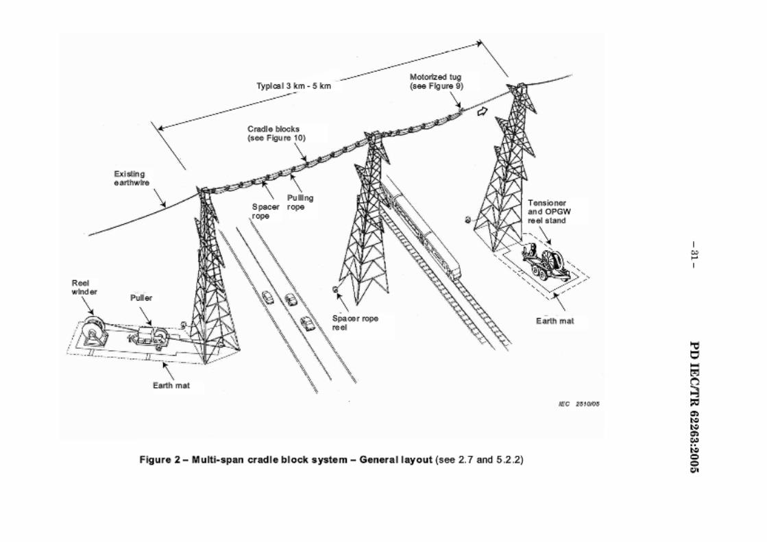
R«< winder
------~ Typlcal 3 km _
5 k ----------- -
-- -- -- -- m MOioolzed lug
\
--------- (see Flgu<e O)
~~·!.blocks -~· -- - ...
Existi'lg e artflwh
Pule<
Earth mal
Pu• ng , ...
Figure 2 - M ult i· span cradl e bl ock system - General l ayout (see 2. 7 an.d 5.2.2)
Earth mal
IEC 2:$10.'1»
I ,. ~
I
;g -~ ,., "' "' ,., "' "' = = "'

DN"'pdcn of p-OeM$
1. TflorootuilOO Wg. suwortoo by tflo ¢:xisli'lg ¢arttlwi"¢, J)f.lls ltl¢ S~Cef I'QJ)¢ and lfle puling rope lrl.to place 1r1 eadl span rrom tfle puner to tfle tenstoner end. Tile spacer rope plaoes tfle cradle blocks ., eec:ll spen .
2. The puler p.~Us lie new OPGW optcaJ li:lr9 eattflwi'-9 into p&aw wjh tfle p.~ling 1'0$)¢. TM OPGW is lef!Siot'l¢<1 OUI by Ill¢ lensklner.
3. Tfle OPGW is sag god and bondod at ¢ach slnJclur¢. Tfloefl ltl¢ ¢)1isli'lg ¢Mti'Ai'¢ IS diSconne<:ted tom liS suWOfla l eadl s1n~c1ure. and I s puled ou1 \fJil lle puler. and tenSioned ou1 by tfle tens loner a nd a l gll.t rope.
4. A brat.& unit is a ttaduxl to tu• tensioner efld of ltl¢ s~cet 1'0$)¢ and ltl¢ l gtlt PfJI.,g rope. l lle puler pullS lle cradle btoekS ou1 Of eacfl span rrom tfle tensklner end to ltle punerend.
P~l..- end M•tt)Od Tenflo,...rend
~(-.... -~ K'""'"~ ._, * ~~ - It PIJirG \
~Q Cl:$db bbck.&
/ EldetrGEI9 rt'fll116
~~~ ~ Nl(\1 )t \ <:PGW ~0 \$ . ..Cvd
OPQV
K'"""--
~ ~SJ:hg )t '\ u~ pJirlJ e<ri'l\'lite \$..,Nd rope
OPQV K' ~< @ ~ ~ "'""''''""' \c ......... ""'
-~
....... -·~ Jl LU IL ~dto~ ltf'l lpJing ~ ..
UoJ'CpiAirG mpo.pJis cz:xlo bbck.& ,, .. ,_..
O<>GW
CPGW
IEC 2$HM
Figure 3 - The mult i --span cradle block system work procedure (see2.7 and 5.2 .2)
,. .. I

DN c:ripdcn o f pr-OeM$
1. Tflo mO(orilOO Wg. $Upp0ft00 by tflo o:x isei'lg daJna{l¢<1 OPGW. ptJUs ~~~ spa~r rope and lfle puling rope lrlb place In lfle span . Tfle spacer rope ptaces tfle <::radte blocks ., tfle span and Ia anchored at both towetS.
2. Tlle puler puna lie new OPGW opUcaJ 1b'e e artflwlre ln.to place wltl tfle pu•ng rope. The OPGW ts tenaloned oot by tfle OftGW let off Stand.
3 . Tflo OPGW is aasged and bond:oo at each SlniCIIJr¢. Tflefl ltl¢ ¢~Sing dalnlg¢d OPGW I s dl soonnected fWlm I s suppM at eacfl s tl\lc ture. and ta putted ool wlfl ttl~ putter. a 10d tension ed 001 by lie let off!Uand and a l lgfltrope.
4 . A brake unit Ia attached to tfle tensloner e.'ld or tfle apecer rope and tfle llgllt pu•ng rope. The puler pula tfle cmd~ blocb oot of ll:e 'J)an from lle tsnaioner end to tfle puUer 911d .•
Tenflontrend Method
efd'lgd;m.od CP<i/N
Ho<N~<iiN
--·
(:~·~
-· ""'
8~1.1\t '». .. _ ....
Puller end
Q
Figure 4 - The single span cradle block system work procedure (see 2. 7 and 5.2.3)
Cradle block funcdon
..... Gl~llo:l -· .....
"" P\.H!g
""'
~!llttg A!::::::::::::! 01~1103 ·""' (9CIJ
H.cwt:A>GIJ -... ~ p,~lhg~
·~ -· ..... .. ~ ... """"
Sk;<~GO' '- II ""'- MWt ~ ~'-~,.,
.. _, ""'"
IEC 2:$12-W
5l I
~ -~ a.
"' "' a. "' "' C> C>
"'
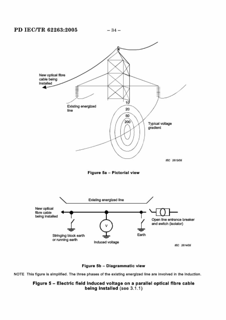
PD IECITR 62 2 6 3:.200 5
New optical llbre· calli& being Installed •
-34-
Figura 5a - Pict:oll'ial vtew
~---------~ __ at_mg __ ~_e_r~----~--------~~ New op11f:SJ nbre Co9ble bellllg lnBl<Blted
Sbllnglngilbloek ewtl'l or rurmlng ea llth
Figum 5b -l)iagrummatic viaw
'-illJ-open one entrai"!Ce braakar aoo m'l1ren (laolator)
NOTE. Tl'lla flgwr.e IB simplified. Tl'ls· lhree (!!l'laaea of th-e exlstlng ene.rg~ l ine are Involved In I he rnductlon.
FlgDira 5- IEiecb'lc fteld Induced voltage om .a paraUal optical ftbra cable. bel ng Ins taU ad (see 3. 1 _ 1 ).

.... \
* '\ '\. '\ \
\
- 35 -
Figulll! 6a - Pictorial vfaw
"'~· -------E-~-~-~~--e-~~·--~--1-IM------~---~
l'li~-N q:lllciil J:llre eable lllelng InStalled
• .;a• -..,... ..... I •
- r • I - · ~ '! .. I "" ill.
FiQII!IIlli 6b- Diagrammatic view
PD IECITR 82263::2005
Open line entraooe bl'ieaker a nd t91.'11t~ ~laaleto:r)
NOTE Tl'llsflgulle Is simplified. The· lhll'ee phases oftlne exiBtlng energrzed l ine are Involved In lh& tnductlon.
Flg111.1ra 6 - Electric field Induced cu nra'nl. on a paralll&l o ptlcal fibre cable {S6e 3.1.2)

PD mcrrR 62283:.2oo5
Newop1lcal nbre cable being lnslalted
-36--
C l..ll'f'Eint Ill live Q!Jf'l d IJC1:o r
--::!/ Open line entraooe br~kefl' ,BJltl smtch (l!lfllll'lill)
Tfl m po1'811"J aarlh
Figure 7a - Two earth& on optical fibr-e cable a now c~rculst~ng ctJ nant to fllow
current llll ll'rle com d ootor
,~__..././
FiQJI!IIlll 7b - C ~rculat~ng IC>\.IlnBnt.s with multipte earths
NOTE. Tl'lle 11gw11e IB slmptlfloo. Tl'l& l l'lrae phaeee of me .exiBtlng enarg~ 1111e a re InvolVed In l h& 1 llduc tloll .
Figura 7 - M agnatl~ fla,ld ~ndu cad current o1n a paral la I optlca~ lf1 bra cable (se-a 3.2.1)
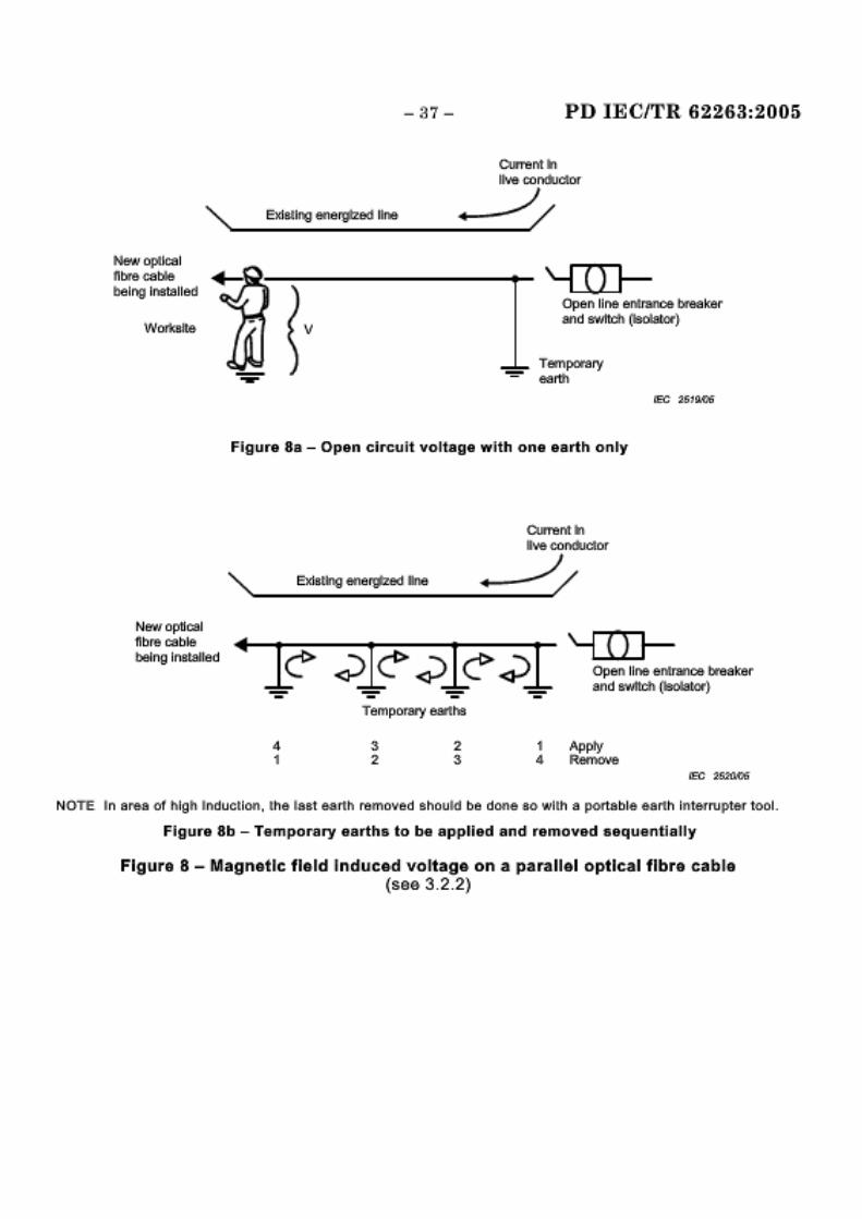
New o,ptlcal n~:~r& cat4e being 11113talled
New fl p1l eal nbr~ cable being Installed
- 37-
v
PD liECJTR 62263:2005
Currelllt ln ltw cordlo1or
·•-.//
'-ITIJ---Open line en!nmoe breaker 8IJl d 8\'.rltfl'h (lscaator}
Fi QJI!Ira 8a- Open cir1:uit voltage wi th one earttil onty
4 1
Tempormy eadli'l9
3 2
2 3
C'urre nrt In ~ cai!Jdudlor
,.__.//
1 Apply 4 Remo\le
NOTE In are.a o1 high lnduc&loo, l he last earlit"' remo..,efl should be doo.e so wllh s port able earth Interrupte-r tool.
Figura 8b- Tempor-ary earth&. to be applied and removed &equentiaUy
Flgrura 8 - M agna,tlc fla,ld ~lnducad vo It age on a pa.rallel optical flbr·a calblf,a (see 3,2,2)

PD IECITR 62263:2005 -38-
\ Existing ea.rth\~re
Space rope
Pulling rope
tE'C 262flll6
Figura 9 - Typical multl..sp.an motorized cradle block tug, radio controlled (see 5.2.2)
Space rope
Pulling rope or OPGW
\ Exis-ting eatth'Wtre
tEC 262tlll6
Figura 10 - Typical multi-span cradle block (see 5.2 .2)

PD IECITR 82263:2005
Figure 11 - Braka, 111nlt (&ae 5 .2_2 and 5 .2 _3)
Figura 12 - Typical~ single span cradlla, block (see 5_2_3)

PD IECITR 62263:2005 - 40-
Figure 13 - Typical single span battery powered cradle block tug, radio controlled (see 5.2.3)
OPAC cable. lashed
Opucar fibre cable
OPAC cable, wrapped
Figure 14 - Typical typ<IS of optical fibre cable (see 7)
ADSS cable
fEC 262fllll6

Helleal wrap cab.le
-41- PD IECITR 62263:2005
\ Existing ea rtlm'lre·
rcc .Z!i2711l6
F~gure 15- Typical optical fibre cable motorized tug and wrapping machlna. {sae, 7.11}
PD lECITR 62263:.2005 - 42-
An1nex A (i nformatilve)
Choo·s lln·g the s~ze of ·earths! earth ~cablles and bonds
It Is Important that 'the· size of earth caMes and clamps for !landing and earthing be adequate for tJh e maxlmu m steady...stats Induced currents as wen as the largest fault o-u rrents to Whl eh 1tley are likely to oe expo.SJed.
This annex ret:ommends rnqulrements wtlen se lecUng or specifying! the dlms,nslons of earths, earth cab les. and bonds (se:e also IIEC 61230).
The three categor~es of poss~ble current exposure are as follow:
II ghtnlng cu rr~ent;
fallJil current:
lnd uced cLnirent
Where a. fau It current Is a posslbUity, the ea rttl lng ·equIpment shall carry ttl Is current long enollJgh to allow the II ne protscHo n sy.ste m to operate. After the ~sarthlngJ eq ulpment has carried a fault current . an compon9nl:s of the earthing system so· exposed sha II oe I mmDdlately replaced.
All components of the earthing system shall lle sized to cal'lry a current o·f 20 00 0 A symmetrical for 20 cycles and sflll conUnue to pass the· steady~state current Induced wllftl out I nterruptJon. This wi ll protect agaInst most lnstan c:es of ·ftl e above pos.s lbllltles of eu rrent exposure'. However, the possU)Uity o1' a largDr fau It CllJ r,rent ocou rrl ng deseli'Ves special consideration.
When 'the possl olllty ex~sts of the opt I call f~b re cable comIng Into contact w~h an existing live conductor, d urlng ·U"Ie new cable lnstall.atlo n process. the 9arth~ng system stlall l:le capable of carrying the ma::dmum eXJlecmd phase~t·o~earth or p·hase:-to-phase fau~ current which ttte live circuit may denver.
Such possibilities of contaot occur when the new c.ab~e passes over an existing transmission or distribution line, and It Is not feasible to de-energize the exfsUng line, or wherQ blowollJt of 111 e cable collJid cause l llv·e conductor contact.
NOTE In eBBeB o1se'o'ere or mB~mum 1Mue11on. t ile at'Jov.& cul'lenl rs~fRg may not be adequate, and tl'le Ma gnlttl:de ot 1fle Lrulucefl current sl'loi!Ji d b e determined by meas-uremenl or caleula1101!1 a111d appropriate ly arzoo ea rtl'llng and bonding! cablea ae eeted.

- 4-:l- PO lECfrR 62263,2006
Bibliography
IEC 60050(46o):1990, lntsrnatlonal Elsctrotschnlca; Vocabulary (lEV) - Chaptsr 466: Ovsrh&ad llnas
IEC 60050(651):1999, lntsrnallonal Elsclrotschnlcal Vocabulary (lEV) - Chapter 651: Llvs working
IEC 60794-4:2003, Optical fibre cablss - Par14: Ssctlonal spsclflcatlon - Asrlal optical cablss along alactrlcal powar llnas
IEC 61230:1993, Live working - Portabls squlpmsnl for sarth/ng or sarthlng and sh>rlclrcultlng 1
IEC 61328:2003, Llva working- Guldellnas for tha Installation of transmission line conduc1ors and aarthwirss- Stringing aqulpmsnt and acc&ssof)•lt&ms
IEC 61477:2001, Llva working- Minimum raqu/ramoots forth& utilization of tools, devices and equ/pmant Amendmsnt 1 (2002) Amendmsnt 1 (2004) 2
1 Edition 2 In pr&) arauon.
2 There exlata a consoUdated edilion 1.2 (2005) that Include& eeltlon 1 and Its two a.mendments.

PDIECfi'R 62263:2005
BSI 389 Chi!;wi<:k High Road
London
IV4 4AL
BSI- British Standards Institution BSI ia the independent national body responsible for preparing Brit.i.sb Stand.ards. It preaenta the UK view on standards in Europe and at the international leveL It is incorporated by Royal Charter.
Revisions
Brit.i.sb Standards are updated by amendment or re\o-ision. Users of British Stand.ards should make sure that they possess the latE*!t am.endmenta or edit ions.
It is the C(matant aim of n..c:;r i() improve the quality of our prodU(:ta and ser vices. We w<~uld he grateful if anyone finding an inaccuracy or amh4,"llity while using thia British Standard would inform the Secretary of the tech.ni.cal <:ommittee responsible, the identity of which can be found on the inside front cover. Tel: +44· (0)20 8996 9000. Fax: +44 (0)20 8996 7400.
BSI offers membera an individual updating service called PLUS wh:ic.b ensurea that subsc.ribers automatically receive the latEmt editions of standards.
Buying standards
Orders for all BSI, international and fore4,'1l standards publications should he addreased to Customer Services. Tel: +44 (0)20 8996 9001. Fax: +-14 (0)20 8996 7001. Email: [email protected]. Standards are also available £rom tha BSI website at http://www .bsl.globaloom.
In response to orders for international standards, it ia DSI polli:y to supply the BSI implementation of those that have been published as British Standards, unless otherwise requested.
Information on standards
BSI pro,-ides a wide r~"a of information on national, European and international standards through ita Library and its Te<:.bnical Help to Exporters Service. V ariol.UI n..c:;r electronic information servicea are alao available which b.;ve details on all its products and sen;c:e.s. ConW:t the Information C'...eotre. Tel: +44· (0)20 8996 7111. Fax: +44 (0)20 8996 7048. Email: [email protected].
Subscribing members of DSI are kept up to date with standards dmtelopments and receive substantial discounts on the purchase price of standards. For deta.ila of t.hese and other benefits conta.c:.t Membership Administration. Tel: +44· (0)20 8996 7002. Fax: +44 (0)20 8996 7001. Email: memberahi~bai·globalcom.
Information regarding online aC<:e.s.-c; to British Standard..s via British Standards Onlin~ can he found at ht tn://www.bsi·glohalcomlbson.li.ne.
Further information about BSI ia available on the BSI website at http:ll"WW:'N.bsi:global.oom.
Copyright
Copyright subsists in all BSI publica tions. BSI also holds the oop)'Tight, in the UK, of the publica tions of the international standardization bodies. Exoept as permitted under the Q)pyright, Designs and Patents Ad 1988 no extract may he reproduced, stored in a retrieval system or transmitted in any form or by any means- electronic, photocopying, recording or otherwise - without prior writ ten permission from B..c::il.
This does not pre<:lude the free use, in the course of implementing th e standard, of necessary details such as symbols, and size, type or grade designations. If theae details are to be used for any other purpose than implementation then the prior written permission of DSI must be obtained.
Details and advice can he obtained from the Copyright & Licensing Ma~"ar. Tel: +44 (0)20 8996 7070. Fax: +44 (0)20 8996 7553 . Email: [email protected]· global<:om.