
IEC 61850 Interface Configuration for Allen-Bradley Protection Relays
9
A A A p p p p p p l l l i i i c c ca a a t t t i i i o o o n n n N N o oo t t t e ee IEC 61850 interface configuration for Allen-Bradley Bulletin 857 and 865 1. Overview This document applies to Allen-Bradley protection relays, which have a so called “native” 61850 interface, this is available starting from software version 10.1. IEC 61850 protocol is available with the op tional inbuilt Ethernet port. IEC 61850 protocol can be used to read / write static data from the relay or to receive events and to receive / send GOOSE messages to other relays. IEC 61850 server interface is capable to do the following: Configurable data model: selection of logical nodes corresponding to active application functions Configurable pre-defined data sets Supported dynamic data sets created by clients Supported reporting function with buffered and unbuffered Report Control Blocks Supported control model: direct with normal security Supported horizontal communication with GOOSE: configurable GOOSE publisher data sets, configurable filters for GOOSE subscriber inputs, GOOSE inputs available in the application logic and ou tput matrix The inbuilt Ethernet is available as communication option, consult the manuals of the individual devices for more information. 2. Configuration The configurat ion of t he 61850 is done with SETP OINTPS. SETPOINTPS ma y be connected to the relay either via serial interface to the front panel connector or via the Ethe rnet network. Correct version of the SETPOINTPS is 2.2.41 or later. Also the ICD file can be generated with SETPOINTPS. 2.1 Setting the main parameters TCP PORT, IP address and NetMask The configuration is started by selecting the IEC-61850 protocol as the “ETHERNET PORT protocol” and setting the IP Address and the NetMask of the device (see figure 2.1-2).
Transcript of IEC 61850 Interface Configuration for Allen-Bradley Protection Relays

7/27/2019 IEC 61850 Interface Configuration for Allen-Bradley Protection Relays
http://slidepdf.com/reader/full/iec-61850-interface-configuration-for-allen-bradley-protection-relays 1/8
AAAppppppllliiicccaaatttiiiooonnn NNNooottteee
IEC 61850 interface configuration for Allen-Bradley
Bulletin 857 and 865 1. Overview
This document applies to Allen-Bradley protection relays, which have a so called
“native” 61850 interface, this is available starting from software version 10.1.
IEC 61850 protocol is available with the optional inbuilt Ethernet port. IEC 61850
protocol can be used to read / write static data from the relay or to receive
events and to receive / send GOOSE messages to other relays.
IEC 61850 server interface is capable to do the following: Configurable data model: selection of logical nodes corresponding to active
application functions
Configurable pre-defined data sets
Supported dynamic data sets created by clients
Supported reporting function with buffered and unbuffered Report Control
Blocks
Supported control model: direct with normal security
Supported horizontal communication with GOOSE: configurable GOOSE
publisher data sets, configurable filters for GOOSE subscriber inputs, GOOSE
inputs available in the application logic and output matrix
The inbuilt Ethernet is available as communication option, consult the manuals of
the individual devices for more information.
2. Configuration
The configuration of the 61850 is done with SETPOINTPS. SETPOINTPS may be
connected to the relay either via serial interface to the front panel connector or
via the Ethernet network. Correct version of the SETPOINTPS is 2.2.41 or later. Alsothe ICD file can be generated with SETPOINTPS.
2.1 Setting the main parameters TCP PORT, IP address and NetMask
The configuration is started by selecting the IEC-61850 protocol as the “ETHERNET
PORT protocol” and setting the IP Address and the NetMask of the device (see
figure 2.1-2).
7/27/2019 IEC 61850 Interface Configuration for Allen-Bradley Protection Relays
http://slidepdf.com/reader/full/iec-61850-interface-configuration-for-allen-bradley-protection-relays 2/8
Application Note 2
Please notice that IP address and netmask must be properly set in reference to
client system in order to get the communication to work properly. In customer
network please consultant with IT responsible to obtain proper addresses allowed
to be used.
Also notify that the device doesn’t support DHCP while PC can obtain different
addresses each time connected to a network. Such trouble might occur especially
if testing the communication in office environment.
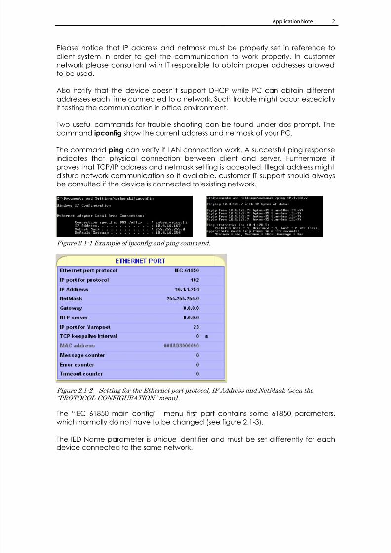
Two useful commands for trouble shooting can be found under dos prompt. The
command ipconfig show the current address and netmask of your PC.
The command ping can verify if LAN connection work. A successful ping response
indicates that physical connection between client and server. Furthermore it
proves that TCP/IP address and netmask setting is accepted. Illegal address might
disturb network communication so if available, customer IT support should always
be consulted if the device is connected to existing network.
Figure 2.1-1 Example of ipconfig and ping command.
Figure 2.1-2 – Setting for the Ethernet port protocol, IP Address and NetMask (seen the “PROTOCOL CONFIGURATION” menu).
The “IEC 61850 main config” –menu first part contains some 61850 parameters,
which normally do not have to be changed (see figure 2.1-3).
The IED Name parameter is unique identifier and must be set differently for each
device connected to the same network.

7/27/2019 IEC 61850 Interface Configuration for Allen-Bradley Protection Relays
http://slidepdf.com/reader/full/iec-61850-interface-configuration-for-allen-bradley-protection-relays 3/8
Application Note 3
Figure 2.1-3 – The “IEC 61850 main config” menu.
2.2 Selecting the Logical Nodes and Datasets for event reporting
The Logical Nodes (LN) to be visible via the IEC 61850 interface are selected in “IEC
61850 data map (1)”… “IEC 61850 data map (n)” (see figures 2.2-1 and figure 2.2-2).
Figure 2.2-1 – IEC 61850 configuration menus in SETPOINTPS.
Data
maps
7/27/2019 IEC 61850 Interface Configuration for Allen-Bradley Protection Relays
http://slidepdf.com/reader/full/iec-61850-interface-configuration-for-allen-bradley-protection-relays 4/8
Application Note 4
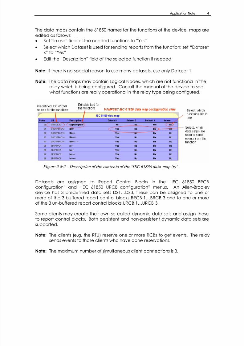
The data maps contain the 61850 names for the functions of the device, maps are
edited as follows:
Set “In use” field of the needed functions to “Yes”
Select which Dataset is used for sending reports from the function: set “Dataset
x” to “Yes”
Edit the “Description” field of the selected function if needed
Note: If there is no special reason to use many datasets, use only Dataset 1.
Note: The data maps may contain Logical Nodes, which are not functional in the
relay which is being configured. Consult the manual of the device to see
what functions are really operational in the relay type being configured.
Figure 2.2-2 – Description of the contents of the “IEC 61850 data map (x)”.
Datasets are assigned to Report Control Blocks in the “IEC 61850 BRCBconfiguration” and “IEC 61850 URCB configuration” menus. An Allen-Bradley
device has 3 predefined data sets DS1…DS3, these can be assigned to one or
more of the 3 buffered report control blocks BRCB 1…BRCB 3 and to one or more
of the 3 un-buffered report control blocks URCB 1…URCB 3.
Some clients may create their own so called dynamic data sets and assign these
to report control blocks. Both persistent and non-persistent dynamic data sets are
supported.
Note: The clients (e.g. the RTU) reserve one or more RCBs to get events. The relay
sends events to those clients who have done reservations.
Note: The maximum number of simultaneous client connections is 3.
7/27/2019 IEC 61850 Interface Configuration for Allen-Bradley Protection Relays
http://slidepdf.com/reader/full/iec-61850-interface-configuration-for-allen-bradley-protection-relays 5/8
Application Note 5
Figure 2.2-3 – Report Control Block configuration.
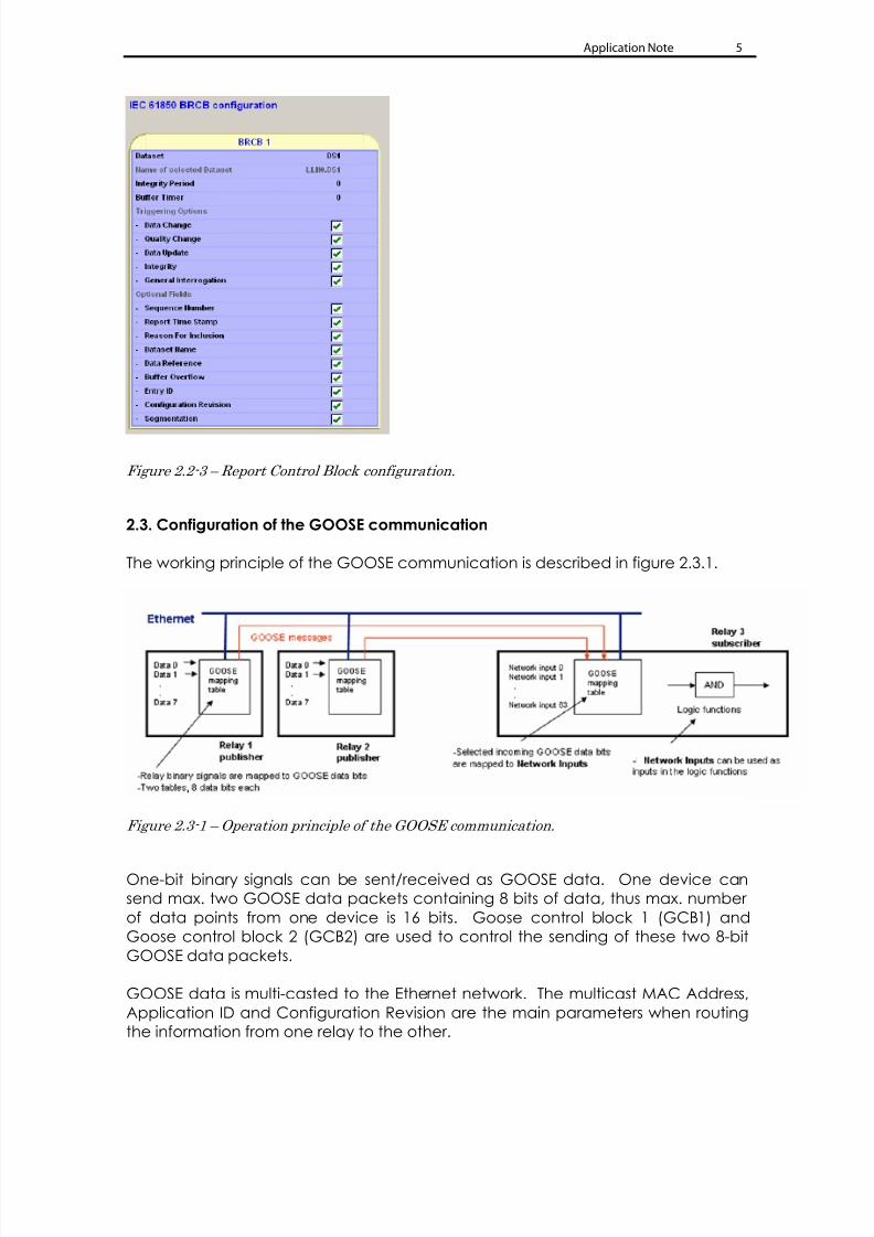
2.3. Configuration of the GOOSE communication
The working principle of the GOOSE communication is described in figure 2.3.1.
Figure 2.3-1 – Operation principle of the GOOSE communication.
One-bit binary signals can be sent/received as GOOSE data. One device can
send max. two GOOSE data packets containing 8 bits of data, thus max. number
of data points from one device is 16 bits. Goose control block 1 (GCB1) and
Goose control block 2 (GCB2) are used to control the sending of these two 8-bit
GOOSE data packets.
GOOSE data is multi-casted to the Ethernet network. The multicast MAC Address,
Application ID and Configuration Revision are the main parameters when routing
the information from one relay to the other.

7/27/2019 IEC 61850 Interface Configuration for Allen-Bradley Protection Relays
http://slidepdf.com/reader/full/iec-61850-interface-configuration-for-allen-bradley-protection-relays 6/8
Application Note 6
Note: The MAC Address used in GOOSE communication is totally independent
from the MAC Addresses of the devices in the Ethernet network!
One device can receive max. 64 bits of GOOSE data. These can be utilized in the
device internal logic and output matrix - these are named as GOOSE NI1…GOOSE
NI64.
The main parameters of the GOOSE communication are available via
“GOOSE configuration” menu (see figure 2.3-2).
Figure 2.3-2 – The main parameters of GOOSE configuration.
Note: Use different “Application ID” in different relays, because this is the main
criteria when receiving GOOSE data in the Allen-Bradley relays. Use also
different “Application ID” for GCB1 and GCB2.
Note: Allen-Bradley relays can receive GOOSE data only via one MAC Address.

7/27/2019 IEC 61850 Interface Configuration for Allen-Bradley Protection Relays
http://slidepdf.com/reader/full/iec-61850-interface-configuration-for-allen-bradley-protection-relays 7/8
Application Note 7
The bit values to be sent are selected in GOOSE mapping tables “GOOSE GCB1:
DATA POINTS” and “GOOSE GCB2: DATA POINTS” (see figure 2.3-3).
Figure 2.3-3 – Examples of selected data bits to be sent in the two 8-bit GOOSE data blocks.
Note: All the lines in the GOOSE GCB data point lists must indicate OK, otherwise
no data is sent (see figure 2.3-3).
The bit values to be received as GOOSE data are defined in “GOOSE Subscriber:
DATA POINTS” (see figure 2.3-4).
Figure 2.3-4 – An example of data point definition to receive GOOSE data.
Note: All devices sending GOOSE data to Allen-Bradley relays must use different
“Application ID”, because this is the main criteria when receiving data in
the Allen-Bradley relays.
2.4 Creating ICD file with SETPOINTPS
IED Capability Description (.ICD) file defines complete capability of an IED. This file
needs to be supplied by each manufacturer to make the complete system
configuration. The file contains a single IED section, an optional communication
section and an optional substation part which denotes the physical entities
corresponding to the IED.

7/27/2019 IEC 61850 Interface Configuration for Allen-Bradley Protection Relays
http://slidepdf.com/reader/full/iec-61850-interface-configuration-for-allen-bradley-protection-relays 8/8
Application Note 8
In order to create the IEC61850 description file connect the device with SetPointPS
and select “COMMUNICATION” ; “Get ICD File”
From the SCL generation options you can select whether the RCB names contain
indexes or not (selection “RCB names with indexes”). The need for indexed or non-
indexed report control blocks depens on the client system - in most of the cases
the indexes are used. Consult the client system manufacturer about this. In case
this is not known, the best way is to create both and test. You can also enable
some features of the 61850 Edition 2 – normally you can skip these.
After selections press OK the .icd-file is generated and you can select directory to
save the .icd file to.
Figure 2.4-1 – Create ICD file with SETPOINTPS program
Medium Voltage Products, 135 Dundas Street, Cambridge, ON, N1R 5X1 Canada, Tel: (1) 519.740.4100, Fax: (1) 519.623.8930, www.ab.com/mvb
Publication 857-AP020A-EN-P – June 2011 Copyright © 2011 Rockwell Automation, Inc. All rights reserved. Printed in Canada.