IEC 61850 bENEFITs - ABB Group · IEC 61850 bENEFITs Figure 1: Reduction in the number of IEDs for...
8
-
Upload
vuongkhanh -
Category
Documents
-
view
226 -
download
0
Transcript of IEC 61850 bENEFITs - ABB Group · IEC 61850 bENEFITs Figure 1: Reduction in the number of IEDs for...

user acceptance for higher degrees of integration. One of the advantages of having a common platform for protection and control is that such functionality as serial communication, event as well as disturbance recording are designed only once for the whole family of IEDs and is available on a more cost-effective basis as compared to dedicated equipment.
On distribution level, it is common practice to combine protection and control in one device per feeder at bay level. For higher voltage levels, however, discussions are still ongoing as to whether such a concept is acceptable. Meanwhile, several utilities have already accepted to go for high integration in transmission networks, using for instance a main 1 device, a main 2 device and a bay controller (only three devices in total) per feeder (additionally, one device in case of a decentralised busbar protection). From the technological point of view, the capabilities needed for higher integration are available today.
A corroborative example can be presented for the case of a one and a half breaker arrangement: A diameter with two lines can be protected and controlled by using only two IEDs (see Figure 1) instead of seven devices previously (one controller per breaker and two protection devices per line). All this integration makes it possible to omit a lot of auxiliary contacts, otherwise needed for signal multiplication in a traditional solution, and to include numerous logics and additional functions such as pulse counters, measurements (e.g. currents and voltage values), disturbance recording, logic gates and timers, etc. inside the few IEDs.
To be able to take full advantage of the new technology, the organisation of the company (utilities, suppliers) needs to be adapted as well. The joint usage of equipment and data sooner or later leads to a closer cooperation of experts for control and protection for certain tasks or even to their grouping in a single entity.
It also induces a change in the specification, going away from a box approach to describing the real requirements (functional requirements, additional requirements with respect to protection philosophy, availability aspects, geographical layout, etc)
without giving the final solution.The approach of basing the specification
on functional requirements without reference to any possible implementation is also a condition to be respected for the proper implementation of optimised solutions based on IEC 61850.
But, independent of the technology used, it is possible to define the required functionality for each type of bay in the substation (e.g. line or transformer or coupler bay for specific voltage levels).
This approach is being used on both the utilities’ and suppliers’ side. Utilities are examining and defining typical bays for the different voltage levels. Suppliers are trying to optimise their processes by also creating standard bay types, based on the choice of the object to be protected and controlled as well as on the voltage level, as illustrated in Figure 2. Flexible suppliers will of course
adapt their different bay types to the requirements of the utilities.
In addition, the required quality of each function (e.g. distance protection, re-closer and control functions) needs to be indicated as in the earlier specifications. This means for instance, that all quality aspects of the functions are to be listed such as characteristics, tripping times, accuracy, etc. This is done per function, independent of the equipment to which the function is allocated.
In conclusion, two basic considerations are important for a technically and economically optimal solution:• Requirements should be functional rather than solution-oriented. The system integrator will propose an optimal solution based on the requirements given by the utility. • Functionality should be placed as close as possible to the primary process. This is the result of experience gained from the implementation of a large number of substation automation systems.
serial communicationWith the introduction of serial communication, several standards have been developed but were limited in their fields of application. With respect to openness, a new standard, IEC 61850, was needed in order to: • Cover the communication issues inside the substation• Ensure interoperability between the functions existing inside the substation (as preliminary condition for inter-changeability)
IEC 61850 bENEFITs
Figure 1: Reduction in the number of IEDs for a one and a half breaker scheme with two lines.
Figure 2: Typical solution at bay level.
feature
33July + August 2008 MEGAWHAT

• Support all types of architectures used, e.g. centralised ones based on RTUs and decentralised ones as used in fully developed substation automation systems• Support different degrees of integration, e.g. high functional integration at bay level or facility to integrate sensors and actuators via process bus• Be future-proof, i.e. to cope with the fast development in communication technology in the slowly evolving application domain of power systems.
These represent very ambitious goals because all functionalities needed in substations had to be examined with respect to their communication behaviour and requirements.
bAsICs OF THE sTANdARd IEC 61850The basic approach of the new standard IEC 61850 can be summarised as follows:• Data model for all functions inside the substation• Substation Configuration description Language (SCL) for a comprehensive description of the complete SA system supporting the goal of interoperability• 100 Mbit/s Ethernet network with switches• Standardised communication mechanisms (services) needed for:• SCADA applications in the substation• Time-critical information exchange• Connection of the primary process.• Methodology:
Object-oriented data model, grouping the data into the smallest possible sets referring to the smallest possible functions to be implemented independently. The smallest possible functions are named “Logical Nodes.”
The standard impacts the whole project execution, from system design to commissioning and maintenance.
IEC 61850: sCAdA applications in the substationSupervisory Control and Data acquisition (SCADA) is one of the basic tasks of a substation automation system. This mainly comprises: [1]• Local and remote operation of the switchgear and other high voltage equipment• Acquisition of switchgear information and power system measurands• Handling of events and alarms.
The SCADA application is related
to human operation of the network and is performed by a local or remote operator. The data communication for this application is directed vertically (Figure 3), i.e. from a higher hierarchical control level down to a lower one (commands of any kind from the operator’s place) or reverse (binary indications like breaker or isolator positions, measurands from instrument transformers and other sensors, events, alarms). It allows to operate and to supervise the power system.
For this vertical relationship, IEC 61850 is using the client-server concept. Here, the server is the local or remote operator’s workplace and the clients are the bay level IEDs. In a client-server communication, the client controls the data exchange. Therefore, client-server communication is very flexible in terms of the data to be transmitted.
Compared to a master-slave system, the client-server concept facilitates the implementation of multiple clients in the same system. Since this communication concept relies on the full seven-layer stack using a confirmed transmission layer, it is highly reliable yet time-consuming. This makes it suitable for communication with an operator having a response time in the order of one second, but unsuitable for time-critical data transmission.
IEC 61850 not only specifies the method of the data transfer. It defines the process data of the servers as well. For this purpose, IEC 61850 uses an object-oriented approach with Logical Nodes (LN) as core objects. This is a functional grouping of data and represents the smallest function, which may be implemented independently in devices. The Logical Nodes, the data and the attributes including their names and semantic interpretation are defined by the standard. Logical Nodes are grouped in Logical Devices and Logical Devices are implemented in physical devices (IEDs).
IEC 61850: Time-criticalinformation exchangeThere are several automated functions in the substation automation system, which require a fast and reliable exchange of binary information between functions located within the same bay or in different bays. A typical example is the exchange of information between bays for station interlocking.
These functions are generally not using human interaction and are time-critical, because they are safety-critical. The maximally accepted communication delay is in the range of several milliseconds. If the functions exchanging the information are located in different IEDs, the information exchange may be done using copper wiring with contacts and auxiliary relays or serial communication. This information exchange is mainly a horizontal communication between devices at the same hierarchical level (Figure 4).
Figure 4: Horizontal communication in the substation automation system with hardwired process interface.
An appropriate communication concept for this purpose is the publisher-subscriber communication. The publisher is distributing the information via the communication network; the subscriber may receive the information according to its needs. For the exchange of this type of (binary) information over serial communication, IEC 61850 introduces a specific information exchange service called GOOSE (Generic Object Oriented Substation Event) based on the publisher-subscriber concept. The content of a GOOSE message is defined with a dataset. GOOSE messages are sent over the communication network
Figure 3: Vertical communication in the substation automation system.
feature
MEGAWHAT July + August 200834
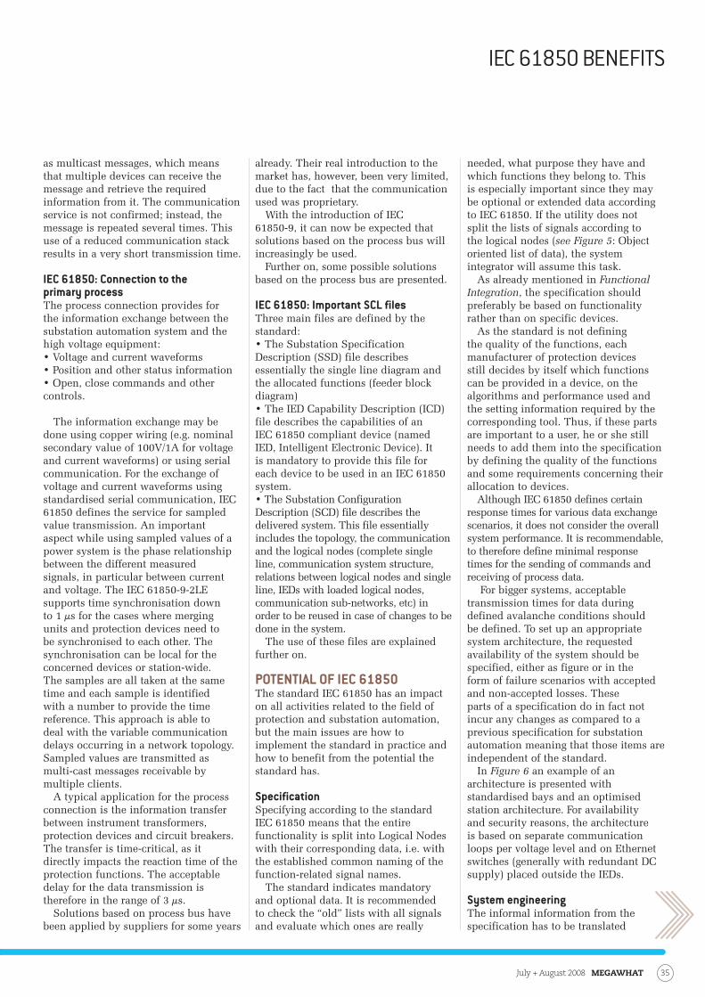
as multicast messages, which means that multiple devices can receive the message and retrieve the required information from it. The communication service is not confirmed; instead, the message is repeated several times. This use of a reduced communication stack results in a very short transmission time.
IEC 61850: Connection to the primary processThe process connection provides for the information exchange between the substation automation system and the high voltage equipment:• Voltage and current waveforms• Position and other status information• Open, close commands and other controls.
The information exchange may be done using copper wiring (e.g. nominal secondary value of 100V/1A for voltage and current waveforms) or using serial communication. For the exchange of voltage and current waveforms using standardised serial communication, IEC 61850 defines the service for sampled value transmission. An important aspect while using sampled values of a power system is the phase relationship between the different measured signals, in particular between current and voltage. The IEC 61850-9-2LE supports time synchronisation down to 1 µs for the cases where merging units and protection devices need to be synchronised to each other. The synchronisation can be local for the concerned devices or station-wide. The samples are all taken at the same time and each sample is identified with a number to provide the time reference. This approach is able to deal with the variable communication delays occurring in a network topology. Sampled values are transmitted as multi-cast messages receivable by multiple clients.
A typical application for the process connection is the information transfer between instrument transformers, protection devices and circuit breakers. The transfer is time-critical, as it directly impacts the reaction time of the protection functions. The acceptable delay for the data transmission is therefore in the range of 3 µs.
Solutions based on process bus have been applied by suppliers for some years
already. Their real introduction to the market has, however, been very limited, due to the fact that the communication used was proprietary.
With the introduction of IEC 61850-9, it can now be expected that solutions based on the process bus will increasingly be used.
Further on, some possible solutions based on the process bus are presented.
IEC 61850: Important sCL filesThree main files are defined by the standard: • The Substation Specification Description (SSD) file describes essentially the single line diagram and the allocated functions (feeder block diagram)• The IED Capability Description (ICD) file describes the capabilities of an IEC 61850 compliant device (named IED, Intelligent Electronic Device). It is mandatory to provide this file for each device to be used in an IEC 61850 system.• The Substation Configuration Description (SCD) file describes the delivered system. This file essentially includes the topology, the communication and the logical nodes (complete single line, communication system structure, relations between logical nodes and single line, IEDs with loaded logical nodes, communication sub-networks, etc) in order to be reused in case of changes to be done in the system.
The use of these files are explained further on.
POTENTIAL OF IEC 61850The standard IEC 61850 has an impact on all activities related to the field of protection and substation automation, but the main issues are how to implement the standard in practice and how to benefit from the potential the standard has.
specificationSpecifying according to the standard IEC 61850 means that the entire functionality is split into Logical Nodes with their corresponding data, i.e. with the established common naming of the function-related signal names.
The standard indicates mandatory and optional data. It is recommended to check the “old” lists with all signals and evaluate which ones are really
needed, what purpose they have and which functions they belong to. This is especially important since they may be optional or extended data according to IEC 61850. If the utility does not split the lists of signals according to the logical nodes (see Figure 5: Object oriented list of data), the system integrator will assume this task.
As already mentioned in Functional Integration, the specification should preferably be based on functionality rather than on specific devices.
As the standard is not defining the quality of the functions, each manufacturer of protection devices still decides by itself which functions can be provided in a device, on the algorithms and performance used and the setting information required by the corresponding tool. Thus, if these parts are important to a user, he or she still needs to add them into the specification by defining the quality of the functions and some requirements concerning their allocation to devices.
Although IEC 61850 defines certain response times for various data exchange scenarios, it does not consider the overall system performance. It is recommendable, to therefore define minimal response times for the sending of commands and receiving of process data.
For bigger systems, acceptable transmission times for data during defined avalanche conditions should be defined. To set up an appropriate system architecture, the requested availability of the system should be specified, either as figure or in the form of failure scenarios with accepted and non-accepted losses. These parts of a specification do in fact not incur any changes as compared to a previous specification for substation automation meaning that those items are independent of the standard.
In Figure 6 an example of an architecture is presented with standardised bays and an optimised station architecture. For availability and security reasons, the architecture is based on separate communication loops per voltage level and on Ethernet switches (generally with redundant DC supply) placed outside the IEDs.
system engineeringThe informal information from the specification has to be translated
IEC 61850 BEnEfIts
35July + August 2008 MEGAWHAT

into a formal description using SCL (Substation Configuration description Language). This will normally be done by the system integrator. The use of SCL warrants high quality, ensures integrity and consistency during the entire implementation process, from the general system design to the final commissioning, facilitating corresponding checks in each step of project execution.
Based on this approach, the system integrator plays an essential role, especially in the multi-vendor environment possible with IEC 61850. It is responsible for elaborating an optimal solution for the user, taking into consideration not only the direct impact of the standard, but also all boundary conditions indicated in the specification such as geographic arrangement, availability aspects, need for process bus, etc.
However, the utility has to decide which role its people should play in conjunction with IEC 61850.
If the utility has just little knowledge about the standard, the adaptation e.g. of the signal lists according to the logical nodes will be done by the system integrator. If the utility has a comprehensive knowledge of the standard, it will be able to elaborate a SSD file (System Specification Description file) describing the single line diagram and the allocated functions. The system integrator will use this file as direct input for the system configuration tool. The use of the SSD file will bring a significant potential for cost saving and elimination of errors due to multiple data entries or misunderstandings. This opens the door for a higher degree of automation in the whole process. In this respect it is also
evident that the system engineering tool is a machine-oriented tool.
It is in any case important that utilities start as soon as possible with using the methodology defined by the standard (e.g. split in logical nodes),
the common naming of functions and signals used in the data model and the substation configuration language.
For building a SA system, it is a prerequisite that the components used are compliant to the standard IEC 61850 and supplied with the so-called ICD files describing the device capabilities. Their proper behaviour should preferably be verified by a detailed test within a complete system environment.
Each IEC 61850-compliant IED can be configured using its dedicated tool. With all these IEDs and their respective tools being compliant with IEC 61850 regarding the standardised data model and data access (services), the system integrator can ensure the integration of third party IEDs into a substation automation system by using an appropriate and powerful tool.
Figure 5: Object-oriented list of data.
Figure 6: Typical IEC 61850 substation automation system with bay solutions and separate communication loops for the transmission and subtransmission levels.
feature
MEGAWHAT July + August 200836
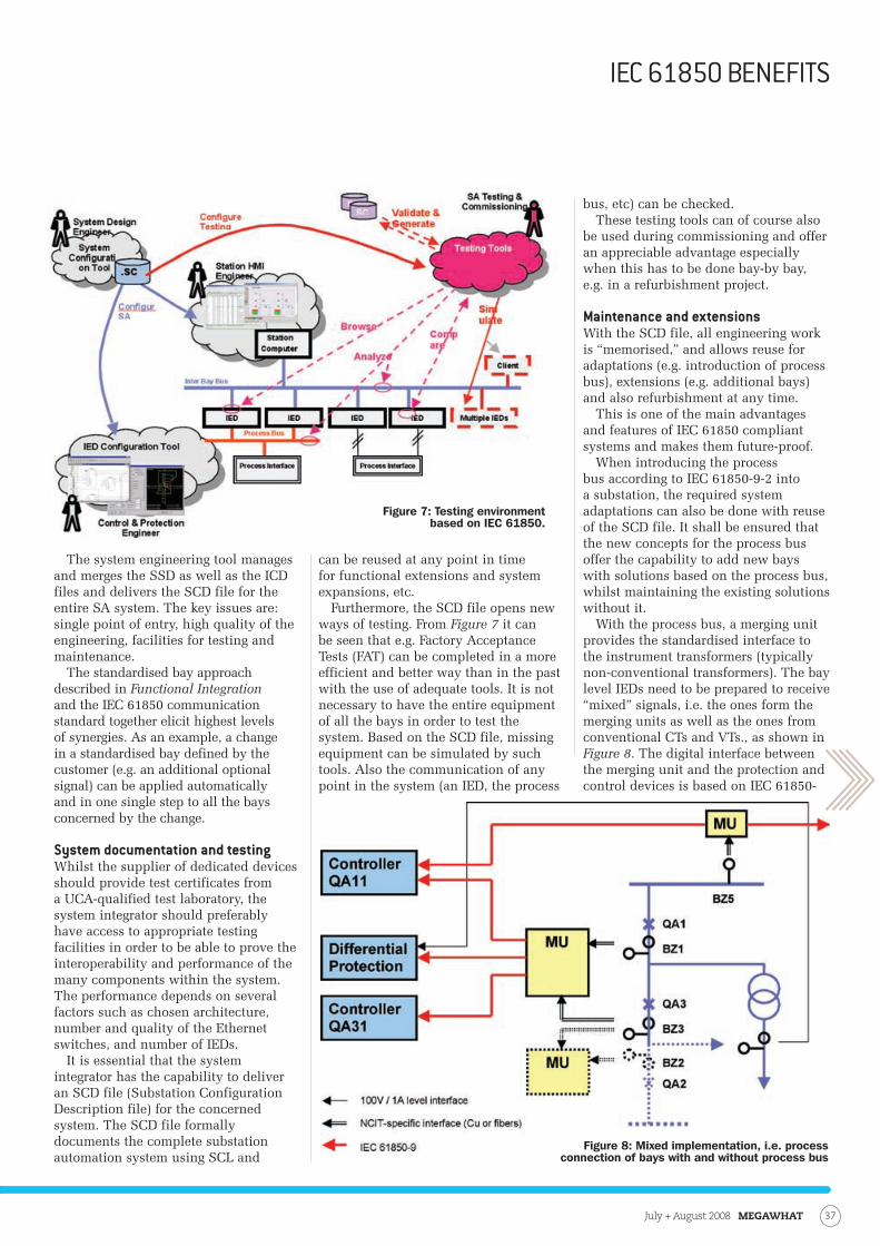
The system engineering tool manages and merges the SSD as well as the ICD files and delivers the SCD file for the entire SA system. The key issues are: single point of entry, high quality of the engineering, facilities for testing and maintenance.
The standardised bay approach described in Functional Integration and the IEC 61850 communication standard together elicit highest levels of synergies. As an example, a change in a standardised bay defined by the customer (e.g. an additional optional signal) can be applied automatically and in one single step to all the bays concerned by the change.
system documentation and testingWhilst the supplier of dedicated devices should provide test certificates from a UCA-qualified test laboratory, the system integrator should preferably have access to appropriate testing facilities in order to be able to prove the interoperability and performance of the many components within the system. The performance depends on several factors such as chosen architecture, number and quality of the Ethernet switches, and number of IEDs.
It is essential that the system integrator has the capability to deliver an SCD file (Substation Configuration Description file) for the concerned system. The SCD file formally documents the complete substation automation system using SCL and
can be reused at any point in time for functional extensions and system expansions, etc.
Furthermore, the SCD file opens new ways of testing. From Figure 7 it can be seen that e.g. Factory Acceptance Tests (FAT) can be completed in a more efficient and better way than in the past with the use of adequate tools. It is not necessary to have the entire equipment of all the bays in order to test the system. Based on the SCD file, missing equipment can be simulated by such tools. Also the communication of any point in the system (an IED, the process
bus, etc) can be checked. These testing tools can of course also
be used during commissioning and offer an appreciable advantage especially when this has to be done bay-by bay, e.g. in a refurbishment project.
Maintenance and extensionsWith the SCD file, all engineering work is “memorised,” and allows reuse for adaptations (e.g. introduction of process bus), extensions (e.g. additional bays) and also refurbishment at any time.
This is one of the main advantages and features of IEC 61850 compliant systems and makes them future-proof.
When introducing the process bus according to IEC 61850-9-2 into a substation, the required system adaptations can also be done with reuse of the SCD file. It shall be ensured that the new concepts for the process bus offer the capability to add new bays with solutions based on the process bus, whilst maintaining the existing solutions without it.
With the process bus, a merging unit provides the standardised interface to the instrument transformers (typically non-conventional transformers). The bay level IEDs need to be prepared to receive “mixed” signals, i.e. the ones form the merging units as well as the ones from conventional CTs and VTs., as shown in Figure 8. The digital interface between the merging unit and the protection and control devices is based on IEC 61850-
Figure 7: Testing environment based on IEC 61850.
Figure 8: Mixed implementation, i.e. process connection of bays with and without process bus
IEC 61850 BEnEfIts
37July + August 2008 MEGAWHAT
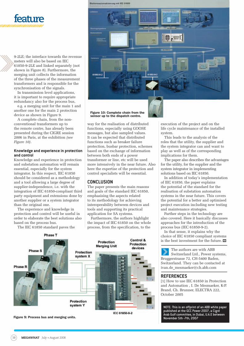
9-2LE; the interface towards the revenue meters will also be based on IEC 61850-9-2LE and linked separately (not shown in Figure 8). Furthermore, the merging unit collects the information of the three phases of the measurement transformers and is responsible for the synchronisation of the signals.
In transmission level applications, it is important to require appropriate redundancy also for the process bus,
e.g. a merging unit for the main 1 and another one for the main 2 protection device as shown in Figure 9.
A complete chain, from the non-conventional transformers up to the remote centre, has already been presented during the CIGRE session 2006 in Paris, at the exhibition (see Figure 10).
Knowledge and experience in protection and controlKnowledge and experience in protection and substation automation will remain essential, especially for the system integrator. In this respect, IEC 61850 should be considered as a methodology and a tool allowing a large degree of supplier-independence, i.e. with the integration of IEC 61850-compliant third party equipment and extensions done by another supplier or a system integrator than the original one.
The experience and knowledge in protection and control will be useful in order to elaborate the best solutions also based on the process bus.
The IEC 61850 standard paves the
way for the realisation of distributed functions, especially using GOOSE messages, but also sampled values. It can be expected that distributed functions such as breaker failure protection, busbar protection, schemes based on the exchange of information between both ends of a power transformer or line, etc will be used more intensively in the near future. Also here the expertise of the protection and control specialists will be essential.
CONCLUsIONThe paper presents the main reasons and goals of the standard IEC 61850, emphasising the aspects related to its methodology for achieving interoperability between devices and tools and supporting its practical application for SA systems.
Furthermore, the authors highlight the impact of IEC 61850 on the whole process, from the specification, to the
execution of the project and on the life cycle maintenance of the installed system.
This leads to the analysis of the roles that the utility, the supplier and the system integrator can and want to play as well as of the corresponding implications for them.
The paper also describes the advantages for the utility, for the supplier and the system integrator in implementing solutions based on IEC 61850.
In addition of today’s implementation of IEC 61850, the paper explains the potential of the standard for the realisation of substation automation systems in the near future. This covers the potential for a better and optimised project execution including new testing and maintenance strategies.
Further steps in the technology are also covered. Here it basically discusses approaches for the introduction of the process bus (IEC 61850-9-2).
In that sense, it explains why the choice of IEC 61850 compliant systems is the best investment for the future.
The authors are with ABB Switzerland Ltd., Power systems,
Bruggerstrasse 72, CH-5400 Baden, Switzerland. They can be contacted at [email protected]
REFERENCEs[1] How to use IEC 61850 in Protection and Automation , I. De Mesmaeker, K-P. Brand, Ch. Brunner, ELECTRA 222, October 2005
Figure 9: Process bus and merging units.
Figure 10: Complete chain from the sensor up to the dispatch centre.
NOTE: This is an offprint of an ABB white paper published at the GCC Power 2007, a Cigré Arab Gulf committee, in Dubai, U.A.E between November 5th -7th, 2007
feature
MEGAWHAT July + August 200838