IEC 61347-2-13 Part 2: Particular requirements: Section...
29
Page 1 of 39 Report No.: GZ12060239-1 Test Report issued under the responsibility of: Intertek Testing Services Shenzhen Ltd. Guangzhou Branch TEST REPORT IEC 61347-2-13 Part 2: Particular requirements: Section Thirteen – d.c. or a.c. supplied electronic controlgear for LED modules Report Number................................: GZ12060239-1 Date of issue .....................................: 27 Jul. 2012 Total number of pages....................... 39 Applicant’s name ............................: Eaglerise Electronics (Foshan) Co., Ltd. Address.............................................: No. 4, East Huanzhen Road, Beijiao, Shunde, Foshan, Guangdong, 528000, China Test specification: Standard ...........................................: IEC 61347-2-13:2006 used in conjunction with IEC 61347-1 (Second Edition) : 2007+A1:2010 EN 61347-2-13:2006 used in conjunction with EN 61347- 1:2008 + A1: 2011 and additional requirements of DIN 57710-14: 1982 (See appendix of TRF No.: IEC61347_2_13C) Test procedure..................................: S + LVD Non-standard test method…………..: N/A Test Report Form No. .....................: IEC61347_2_13C Test Report Form(s) Originator ........: Intertek Semko AB Master TRF .......................................: 2011-06 Copyright © 2011 IEC System for Conformity Testing and Certification of Electrical Equipment (IECEE), Geneva, Switzerland. All rights reserved. This publication may be reproduced in whole or in part for non-commercial purposes as long as the IECEE is acknowledged as copyright owner and source of the material. IECEE takes no responsibility for and will not assume liability for damages resulting from the reader's interpretation of the reproduced material due to its placement and context. If this Test Report Form is used by non-IECEE members, the IECEE/IEC logo and the reference to the CB Scheme procedure shall be removed. This report is not valid as a CB Test Report unless signed by an approved CB Testing Laboratory and appended to a CB Test Certificate issued by an NCB in accordance with IECEE 02.
Transcript of IEC 61347-2-13 Part 2: Particular requirements: Section...

Page 1 of 39 Report No.: GZ12060239-1
Test Report issued under the responsibility of: Intertek Testing Services Shenzhen Ltd.
Guangzhou Branch
TEST REPORT IEC 61347-2-13
Part 2: Particular requirements: Section Thirteen – d.c. or a.c. supplied electronic controlgear for
LED modules
Report Number................................: GZ12060239-1
Date of issue.....................................: 27 Jul. 2012
Total number of pages....................... 39
Applicant’s name ............................: Eaglerise Electronics (Foshan) Co., Ltd.
Address.............................................: No. 4, East Huanzhen Road, Beijiao, Shunde, Foshan, Guangdong, 528000, China
Test specification:
Standard ...........................................: IEC 61347-2-13:2006 used in conjunction with IEC 61347-1 (Second Edition) : 2007+A1:2010
EN 61347-2-13:2006 used in conjunction with EN 61347-1:2008 + A1: 2011 and additional requirements of DIN 57710-14: 1982 (See appendix of TRF No.: IEC61347_2_13C)
Test procedure..................................: S + LVD
Non-standard test method…………..: N/A
Test Report Form No. .....................: IEC61347_2_13C
Test Report Form(s) Originator ........: Intertek Semko AB
Master TRF.......................................: 2011-06
Copyright © 2011 IEC System for Conformity Testing and Certification of Electrical Equipment (IECEE), Geneva, Switzerland. All rights reserved. This publication may be reproduced in whole or in part for non-commercial purposes as long as the IECEE is acknowledged as copyright owner and source of the material. IECEE takes no responsibility for and will not assume liability for damages resulting from the reader's interpretation of the reproduced material due to its placement and context.
If this Test Report Form is used by non-IECEE members, the IECEE/IEC logo and the reference to the CB Scheme procedure shall be removed. This report is not valid as a CB Test Report unless signed by an approved CB Testing Laboratory and appended to a CB Test Certificate issued by an NCB in accordance with IECEE 02.

Page 2 of 39 Report No.: GZ12060239-1
TRF No. IEC61347_2_13C
Test item description..................... : Electronic controlgear for LED (Electronic LED driver)
Trade Mark .......................................:
Manufacturer.....................................: Same as applicant
Model/Type reference.......................: EIP012C****LS Remark: The 1st to 4th “*” indicate the output current of LED driver; can be replaced by “0250” to “1200” and increasing in multiplies of 50. “0250” means 250 mA; “1200” means 1200 mA.
Ratings..............................................: Input: 220-240 VAC; 50/60 Hz; 0,09 A; Class II; IP 20; SELV; ta 50 °C; tc 75 °C; Independent type; 110 °C thermal protection; Inherently short-circuit proof; Output: Constant current type for output; MM mark; Suitable for direct mounting on normally flammable surfaces; Other parameters refer to appendix for model list.


Page 4 of 39 Report No.: GZ12060239-1
TRF No. IEC61347_2_13C
List of Attachments (including a total number of pages in each attachment): This report is totally 39 pages; Page 1-31 is test report; Page 32 is model list; Page 33-39 is product photos.
Summary of testing: The test samples fulfilled the requirement of the standard. All models had the same mechanical structure, output load, PCB layout; the only deference is the parameters for the components used in secondary circuit. Model EIP012C1200LS was selected to do the full tests as its maximum secondary output current. Models EIP012C0700LS; EIP012C0250LS were also selected to do abnormal conditions test and construction check.
Tests performed (name of test and test clause): 7 Marking 8 Protection against accidental contact with live parts9 Terminals 11 Moisture resistance and insulation 12 Electric strength 14 Fault conditions 16 Abnormal conditions 17 Construction 18 Creepage distances and clearances 19 Screws, current-carrying parts and connections 20 Resistance to heat, fire and tracking 21 Resistance to corrosion Annex C Particular requirements for electronic lamp controlgear with means of protection against overheating Annex I Particular additional requirements for independent SELV d.c. or a.c. supplied electronic step-down convertors for filament lamps
Testing location: Block E, No.7-2 Guang Dong Software Science Park, Caipin Road, Guangzhou Science City, GETDD, Guangzhou, China
Summary of compliance with National Differences: Not checked.

Page 5 of 39 Report No.: GZ12060239-1
TRF No. IEC61347_2_13C
Copy of marking plate The artwork below may be only a draft. The use of certification marks on a product must be authorized by the respective NCBs that own these marks.
(Representative)
Location: attached on the enclosure and visible during installation
Remark on above marking:
1. The height of graphical symbols shall not be less than 5 mm;
2. The height of letters and numerals shall be not less than 2 mm.

Page 6 of 39 Report No.: GZ12060239-1
TRF No. IEC61347_2_13C
Test item particulars...............................................:
Classification of installation and use.........................: Independent; Class II; for use with LED
Supply Connection....................................................: Terminal blocks
Possible test case verdicts:
- test case does not apply to the test object .............: N/A
- test object does meet the requirement...................: P (Pass)
- test object does not meet the requirement.............: F (Fail)
Testing .....................................................................:
Date of receipt of test item........................................: 05 Jun. 2012
Date (s) of performance of tests ...............................: 05 Jun. 2012 to 27 Jul. 2012

Page 7 of 39 Report No.: GZ12060239-1
TRF No. IEC61347_2_13C
General remarks:
The test results presented in this report relate only to the object tested. This report shall not be reproduced, except in full, without the written approval of the Issuing testing laboratory. "(See Enclosure #)" refers to additional information appended to the report. "(See appended table)" refers to a table appended to the report. Throughout this report a comma is used as the decimal separator. Clause numbers between brackets refer to clauses in IEC 61347-1. When determining for test conclusion, measurement uncertainty of tests has been considered. This report is for the exclusive use of Intertek's Client and is provided pursuant to the agreement between Intertek and its Client. Intertek's responsibility and liability are limited to the terms and conditions of the agreement. Intertek assumes no liability to any party, other than to the Client in accordance with the agreement, for any loss, expense or damage occasioned by the use of this report. Only the Client is authorized to permit copying or distribution of this report and then only in its entirety. Any use of the Intertek name or one of its marks for the sale or advertisement of the tested material, product or service must first be approved in writing by Intertek. The observations and test results in this report are relevant only to the sample tested. This report by itself does not imply that the material, product, or service is or has ever been under an Intertek certification program. The test report only allows to be revised only within the report defined retention period unless standard or regulation was withdrawn or invalid. The clause which indicated with * is the subcontract test item. This report should be read with test report GZ12060239-2 for Additional requirements of independent Electronic controlgear for LED according to standard EN 60598-2-6:1994+A1:1997 used in conjunction with EN 60598-1:2008+A11: 2009. EMF requirement according to EN 62493: 2010 has been considered.
Manufacturer’s Declaration per sub-clause 6.2.5 of IECEE 02:
The application for obtaining a CB Test Certificate includes more than one factory location and a declaration from the Manufacturer stating that the sample(s) submitted for evaluation is (are) representative of the products from each factory has been provided ..............................................................:
Yes Not applicable
When differences exist; they shall be identified in the General product information section.
Name and address of factory (ies) ...................... :
Name: Eaglerise Electronics (Foshan) Co., Ltd. Address: No. 4, East Huanzhen Road, Beijiao, Shunde, Foshan, Guangdong, 528000, China.
General product information: The products covered by this report are independent; SELV; LED driver.

Page 8 of 39 Report No.: GZ12060239-1
IEC 61347-2-13
Clause Requirement + Test Result - Remark Verdict
TRF No. IEC61347_2_13C
4 GENERAL REQUIREMENTS P
Compliance of independent controlgear enclosure with EN 60 598-1
P
Independent SELV controlgear comply with Annex I
(see Annex I) P
6 (6) CLASSIFICATION —
Independent convertor.......................................... : Yes No ⎯
Built-in convertor .................................................. : Yes No ⎯
Integral convertor ................................................. : Yes No ⎯
SELV-equivalent or isolating convertor ............... : Yes No ⎯
Auto-wound convertor .......................................... : Yes No ⎯
Independent SELV controlgear ............................ : Yes No ⎯
7 MARKING P
7.1 (7.1) Mandatory markings: P
- mark of origin P
- model number, type reference .......................... : EIP012C1200LS (Representative)
P
- symbol for independent convertor, if applicable P
- correlation between interchangeable parts and convertor marked
N/A
- rated supply voltage (V) .................................... : 220-240 P
- earthing symbol N/A
- wiring diagram P
- value of tc 75 °C P
- symbol for declared temperature 110 °C P
Constant voltage type: Yes No ⎯
- rated supply voltage (V) .................................... : N/A
Constant current type: Yes No ⎯
- rated output current (A) ..................................... : 1200 mA P
- rated maximum output voltage (V) .................... : 13 VDC P
- indication if for LED modules only N/A
7.2 (7.1) - information to be provided, if applicable: P
- declaration on protection against accidental contact
P

Page 9 of 39 Report No.: GZ12060239-1
IEC 61347-2-13
Clause Requirement + Test Result - Remark Verdict
TRF No. IEC61347_2_13C
- cross-section of conductors (mm²) .................... : Input: 0,5~0,75 mm2; Output: 0,5~1,5 mm2
P
- number, type and wattage of lamp(s) P
- declaration of mains connected windings N/A
- declaration for SELV-equivalent convertor N/A
- (7.2) Marking durable and legible P
Rubbing 15 s water, 15 s petroleum; marking legible
P
8 (10) PROTECTION AGAINST ACCIDENTAL CONTACT WITH LIVE PARTS P
- (10.1) Controlgear protected against accidental contact with live parts
P
- (A2) The current flowing between the part concerned and earth is measured and does not exceed 0,7 mA (peak) or 2 mA d.c. .................................. :
N/A
- (A2) For frequencies above 1 kHz, the current does not exceed 0,7 mA (peak) multiplied by the value of the frequency in kilohertz or 70 mA (peak) ...... :
N/A
- (A3) The voltage between the part concerned and any accessible part is measured and does not exceed 34 V (peak) ........................................................... :
N/A
- (10.1) Lacquer or enamel not used for protection or insulation
P
Adequate mechanical strength on parts providing protection
P
- (10.2) Capacitors > 0,5 μF: voltage after 1 min (V): < 50 V .................................................................. :
Max. 0,148 μF Measured max. 8,9 V peak discharged voltage after 1 second.
N/A
8.1 SELV-equivalent controlgear accessible parts are insulated from live parts by double or reinforced insulation according 8.6 and 13.1 in IEC 60065
N/A
8.2 Exposed terminals of SELV or SELV-equivalent controlgear if: - the rated or maximum rated output voltages ≤ 25 V r.m.s. - the no-load output voltage ≤ 30 V r.m.s. or 33 √2 V peak
N/A
Insulated terminals if convertor with rated output voltage > 25 V
N/A
One capacitor Y1 or two capacitors Y2 complying with IEC 60384-14 of the same values used in series between SELV or SELV-equivalent output and primary circuits
One Y1 capacitor P

Page 10 of 39 Report No.: GZ12060239-1
IEC 61347-2-13
Clause Requirement + Test Result - Remark Verdict
TRF No. IEC61347_2_13C
Other components bridging the separating transformer complying with IEC 60065, clause 14
N/A
9 (8) TERMINALS P
Separately approved, component list (see Annex 1) P
Screw terminals: compliance with Section 14 of IEC 60598-1
(see Annex 2) N/A
Screwless terminals: compliance with Section 15 of IEC 60598-1
(see Annex 3) N/A
10 (9) PROVISION FOR EARTHING N/A
Terminal complying with clause 8 in Part 1 N/A
Locked against loosening and not possible to loosen by hand
N/A
Not possible to loosen clamping means unintentionally on screwless terminals
N/A
Earthing via means of fixing N/A
Earthing terminal only used for the earthing of the control gear
N/A
All parts of material minimizing the danger of electrolytic corrosion
N/A
Made of brass or equivalent material N/A
Contact surface bare metal N/A
Earth contact via the track on the printed board N/A
Test with a current of 25 A between earthing terminal and each of the accessible metal parts; measured resistance (Ω): < 0,5 Ω ....................... :
N/A
11 (11) MOISTURE RESISTANCE AND INSULATION P
After storage 48 h at 91-95% relative humidity and 20-30 °C measuring of insulation resistance with d.c. 500 V (MΩ):
P
For basic insulation ≥ 2 MΩ ................................. : >100 MΩ P
For double or reinforced insulation ≥ 4 MΩ ......... : >100 MΩ P
Adequate insulation between input and output terminals not bounded together in SELV-equivalent controlgear
⎯
12 (12) ELECTRIC STRENGTH P
Immediately after clause 11 electric strength test for 1 min P

Page 11 of 39 Report No.: GZ12060239-1
IEC 61347-2-13
Clause Requirement + Test Result - Remark Verdict
TRF No. IEC61347_2_13C
Working voltage ≤ 42 V, test voltage 500 V 500 V P
Working voltage > 42 V ≤ 1000 V, test voltage (V): P
Basic insulation, 2U + 1000 V 1480 V P
Supplementary insulation, 2U + 1750 V N/A
Double or reinforced insulation, 4U + 2750 V 3710 V P
No flashover or breakdown P
Windings in separating transformers in SELV-equivalent convertors according to 14.3.2 of IEC 60065
N/A
14 (14) FAULT CONDITIONS (Carried out on three samples) P
When operated under fault conditions the controlgear: P
- does not emit flames or molten material P
- does not produce flammable gases P
- protection against accidental contact not impaired
P
Thermally protected ballasts does not exceed the marked temperature value
P
Fault conditions: capacitors, resistors or inductors without proof of compliance with relevant specifications have been short-circuited or disconnected
P
- (14.1) Short-circuit of creepage distances and clearances if less than specified in clause 18 (except between live parts and accessible metal parts)
(see appended table) N/A
Creepage distances on printed boards less than specified in clause 18 provided with coating according to IEC 60664-3
N/A
- (14.2) Short-circuit or interruption of semiconductor devices
(see appended table) P
- (14.3) Short-circuit across insulation consisting of lacquer, enamel or textile
(see appended table) P
- (14.4) Short-circuit across electrolytic capacitors (see appended table) P
- (14.5) After the tests has been carried out on three samples: P
The insulation resistance ≥ 1 MΩ >100 MΩ P
No flammable gases P
No accessible parts have become live P
During the tests, a five-layer tissue paper, where the test specimen is wrapped, does not ignite
P
Page 12 of 39 Report No.: GZ12060239-1
IEC 61347-2-13
Clause Requirement + Test Result - Remark Verdict
TRF No. IEC61347_2_13C
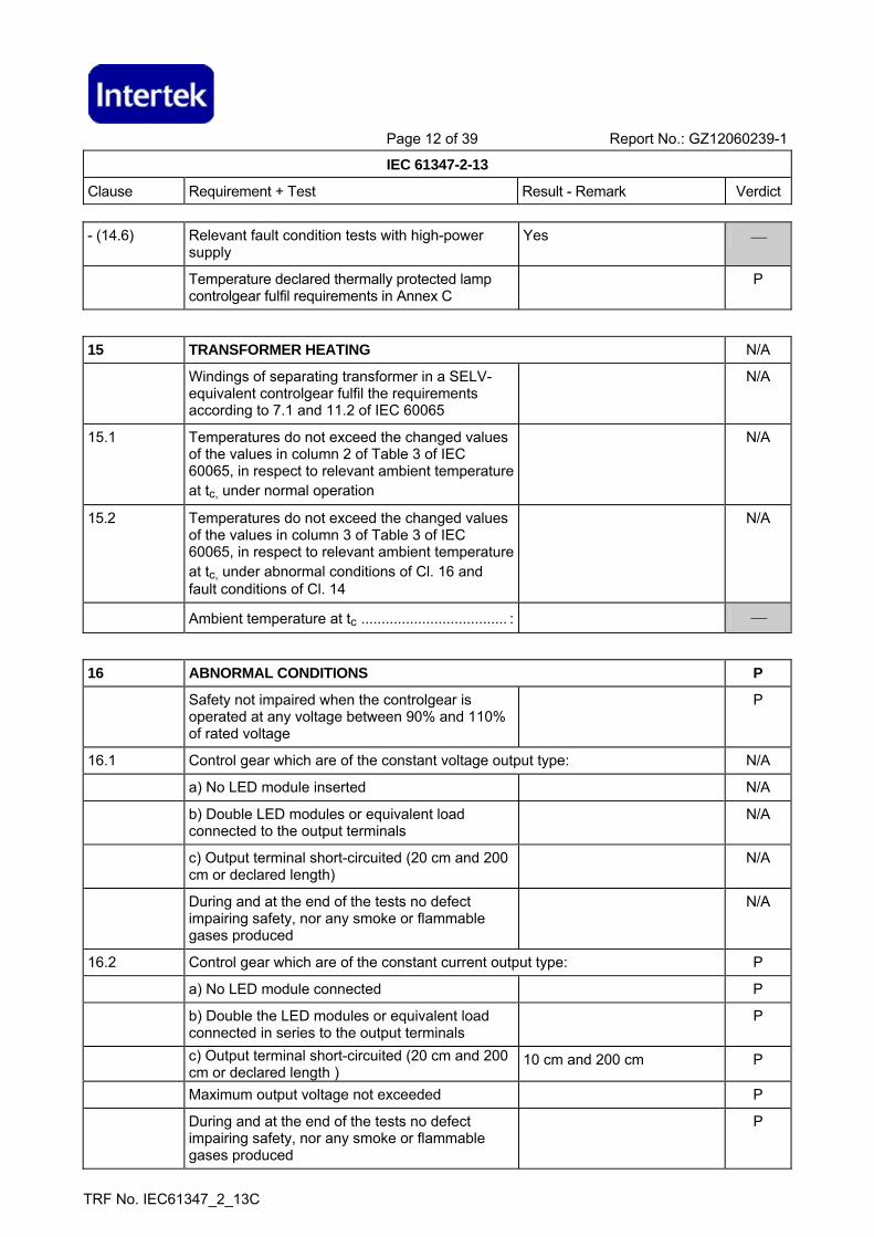
- (14.6) Relevant fault condition tests with high-power supply
Yes ⎯
Temperature declared thermally protected lamp controlgear fulfil requirements in Annex C
P
15 TRANSFORMER HEATING N/A
Windings of separating transformer in a SELV-equivalent controlgear fulfil the requirements according to 7.1 and 11.2 of IEC 60065
N/A
15.1 Temperatures do not exceed the changed values of the values in column 2 of Table 3 of IEC 60065, in respect to relevant ambient temperature at tc, under normal operation
N/A
15.2 Temperatures do not exceed the changed values of the values in column 3 of Table 3 of IEC 60065, in respect to relevant ambient temperature at tc, under abnormal conditions of Cl. 16 and fault conditions of Cl. 14
N/A
Ambient temperature at tc .................................... : ⎯
16 ABNORMAL CONDITIONS P
Safety not impaired when the controlgear is operated at any voltage between 90% and 110% of rated voltage
P
16.1 Control gear which are of the constant voltage output type: N/A
a) No LED module inserted N/A
b) Double LED modules or equivalent load connected to the output terminals
N/A
c) Output terminal short-circuited (20 cm and 200 cm or declared length)
N/A
During and at the end of the tests no defect impairing safety, nor any smoke or flammable gases produced
N/A
16.2 Control gear which are of the constant current output type: P
a) No LED module connected P
b) Double the LED modules or equivalent load connected in series to the output terminals
P
c) Output terminal short-circuited (20 cm and 200 cm or declared length )
10 cm and 200 cm P
Maximum output voltage not exceeded P
During and at the end of the tests no defect impairing safety, nor any smoke or flammable gases produced
P

Page 13 of 39 Report No.: GZ12060239-1
IEC 61347-2-13
Clause Requirement + Test Result - Remark Verdict
TRF No. IEC61347_2_13C
17 (15) CONSTRUCTION P
- (15.1) Wood, cotton, silk, paper and similar fibrous material not used as insulation
P
- (15.2) Printed boards used as internal connections complies with clause 14
P
Socket-outlet in the output circuit does not accept plugs complying with IEC 60083 and IEC 60906
N/A
Not possible to engage plugs accepted by socket-outlet in the output circuit with socket-outlets complying with IEC 60083 and IEC 60906
N/A
18 (16) CREEPAGE DISTANCES AND CLEARANCES P
Creepage distances and clearances according to Table 3 and 4, as appropriate
(see appended table) P
Printed boards see clause 14 P
Insulating lining of metallic enclosures N/A
19 (17) SCREWS, CURRENT-CARRYING PARTS AND CONNECTIONS P
Screws, current-carrying parts and connections in compliance with IEC 60598-1 (clause numbers between parentheses refer to IEC 60598-1)
P
(4.11) Electrical connections P
(4.11.1) Contact pressure P
(4.11.2) Screws: N/A
- self-tapping screws N/A
- thread-cutting screws N/A
- at least two self-tapping screws N/A
(4.11.3) Screw locking: N/A
- spring washer N/A
- rivets N/A
(4.11.4) Material of current-carrying parts P
(4.11.5) No contact to wood P
(4.12) Mechanical connections and glands N/A
(4.12.1) Mechanical stress P
Screws not made of soft metal P
Screws of insulating material N/A
Torque test: part; torque (Nm) ............................. : Fixed enclosure screw: 0,5 Nm
P

Page 14 of 39 Report No.: GZ12060239-1
IEC 61347-2-13
Clause Requirement + Test Result - Remark Verdict
TRF No. IEC61347_2_13C
Torque test: part; torque (Nm) ............................. : N/A
Torque test: part; torque (Nm) ............................. : N/A
(4.12.2) Screw diameter < 3 mm screwed into metal N/A
(4.12.4) Locked connections N/A
(4.12.5) Screwed glands: force (N) ................................... : N/A
20 (18) RESISTANCE TO HEAT, FIRE AND TRACKING P
- (18.1) Parts of insulating material retaining live parts in position, ball-pressure test: P
- part; test temperature (°C) ................................. : Enclosure; 95 °C P
- part; test temperature (°C) ................................. : Bobbin of T2; 125 °C P
- (18.2) Printed boards in accordance with 8.7 of IEC 61189-2 and relevant parts of IEC 61249-2
N/A
- (18.3) External parts of insulating material preventing electric shock glow-wire test 650 °C
Enclosure P
- (18.4) Parts of insulating material retaining live parts in position, needle-flame test 10 s: P
- flame extinguished within 30 s Bobbin of T2 P
- no flaming drops igniting tissue paper P
- (18.5) Tracking test according section 13 of IEC 60598-1 if required
N/A
21 (19) RESISTANCE TO CORROSION N/A
Applicable parts comply with 4.18.1 of IEC 60598-1
N/A
Adequate varnish on the outer surface N/A
- (20) NO-LOAD OUTPUT VOLTAGE N/A
No load output voltage not differ more than 10 % from rated voltage
N/A
14 TABLE: tests of fault conditions P
Part Simulated fault Hazard
DB1 primary input (Un=240V)
Short-circuited; No hazards, F1 broken No
C2 Short-circuited; No hazards, C12 broken No
C8 Short-circuited; No hazards, recoverable when removed the fault No

Page 15 of 39 Report No.: GZ12060239-1
IEC 61347-2-13
Clause Requirement + Test Result - Remark Verdict
TRF No. IEC61347_2_13C
C7 Short-circuited; No hazards, recoverable when removed the fault No
D1 Short-circuited; No hazards, R11 broken No
D3 Short-circuited; No hazards, recoverable when removed the fault No
D5 Short-circuited; No hazards, C12 broken No
D7 Short-circuited; No hazards, C2 broken No
Q1 (c&e) Short-circuited; No hazards, recoverable when removed the fault No
18 (16) TABLE: creepage distances and clearances N/A
Minimum distances for a.c. (50/60 Hz) sinusoidal voltages N/A
RMS working voltage (V) not exceeding 50 150 250 500 750 1000
1) minimum distances between live parts of different polarity. Specify the value measured.
2) minimum distances between live parts and accessible parts which are permanently fixed to the ballast, including screws or devices for fixing covers or fixing the ballast to its support. Specify the value measured.
- required creepage distances (mm), insulation PTI ≥ 600
0,6 1,4 1,7 3 4 5,5
- required creepage distances (mm), insulation PTI < 600
1,2 1,6 2,5 5 8 10
- required clearances (mm) 0,2 1,4 1,7 3 4 5,5
3) minimum distances between live parts and a flat supporting surface or a loose metal cover, if any, if the construction does not ensure that the values under 2 above are maintained under the most unfavourable circumstances
- required clearances (mm) 2 3,2 3,6 4,8 6 8
Minimum distances for non-sinusoidal pulse voltages N/A

Page 16 of 39 Report No.: GZ12060239-1
IEC 61347-2-13
Clause Requirement + Test Result - Remark Verdict
TRF No. IEC61347_2_13C
rated pulse voltage (peak kV) 2,0 2,5 3,0 4,0 5,0 6,0 8,0
required minimum distances, clearances (mm)
1,0 1,5 2 3 4 5,5 8
Specify the value measured
rated pulse voltage (peak kV) 10 12 15 20 25 30 40
required minimum distances, clearances (mm)
Specify the value measured
rated pulse voltage (peak kV) 50 60 80 100 - - -
required minimum distances, clearances (mm)
75 90 130 170 - - -
Specify the value measured

Page 17 of 39 Report No.: GZ12060239-1
IEC 61347-2-13
Clause Requirement + Test Result - Remark Verdict
TRF No. IEC61347_2_13C
A ANNEX A (NORMATIVE), TEST TO ESTABLISH WHETHER A CONDUCTIVE PART IS A LIVE PART WHICH MAY CAUSE AN ELECTRIC SHOCK
N/A
A.2 See clause 8 A.2 in this Test Report N/A
A.3 See clause 8 A.3 in this Test Report N/A
C ANNEX C – PARTICULAR REQUIREMENTS FOR ELECTRONIC LAMP CONTROLGEAR WITH MEANS OF PROTECTION AGAINST OVERHEATING
P
C3 GENERAL REQUIREMENTS P
C3.1 Thermal protection means integral with the convertor, protected against mechanical damage
P
Renewable only by means of a tool N/A
If function depending on polarity, for cord-connected equipment protection means in both leads
N/A
Thermal links comply with IEC 60691 N/A
Electrical controls comply with IEC 60730-2-3 N/A
C3.2 No risk of fire by breaking (clause C7) P
C5 CLASSIFICATION P
a) automatic resetting type No ⎯
b) manual resetting type No ⎯
c) non-renewable, non-resetting type No ⎯
d) renewable, non-resetting type No ⎯
e) other type of thermal protection; description ... : Yes, Inherently circuit feedback protection
P
C6 MARKING P
C6.1 Symbol for temperature declared thermally protected ballasts
110 °C P
C6.2 Declaration of the type of protection provided In the user manual P
C7 LIMITATION OF HEATING P
C7.1 Preselection test: P
Test sample placed for at least 12 h in an oven having temperature (tc - 5) K
70 °C P
No operation of the protection device P
C7.2 Functioning of protection means P
Normal operation of the sample in a test enclosure according to Annex D at an ambient temperature such that (tc +0; -5) °C is obtained
P
No operation of the protection device P

Page 18 of 39 Report No.: GZ12060239-1
IEC 61347-2-13
Clause Requirement + Test Result - Remark Verdict
TRF No. IEC61347_2_13C
Introducing of the most onerous test condition determined during test of clause 14
P
Output of windings connected to the mains supply short-circuited, and other part of the convertor operated under normal conditions
N/A
Increasing of the current through the windings continuously until operation of the protection means
P
Continuous measuring of the highest surface temperature
P
Ballasts according to C5 a) or C5 e) operated until stable conditions are achieved
P
Automatic-resetting thermal protectors working 3 times
N/A
Ballasts according to C5 b) working 6 times N/A
Ballasts according to C5 c) and C5) d) working once
N/A
Highest temperature does not exceed the marked value
Measured Max. 85 °C P
Any overshoot of 10% over the marked value within 15 min
N/A
D ANNEX D – REQUIREMENTS FOR CARRY OUT THE HEATING TESTS OF THERMALLY PROTECTED LAMP CONTROLGEAR
P
Tests in C7 performed in accordance with Annex D, if applicable
P
E ANNEX E – USE OF CONSTANT S OTHER THAN 4500 IN tw TESTS N/A
Annex E if windings of 50 Hz/60 Hz N/A
E1 Constant S claimed N/A
Claimed test method N/A
E2 Procedure A N/A
Adequate data provided by the manufacturer N/A
The inverse of the slope is greater than or equal to the claimed value of S
N/A
Compliance with the failure criteria for procedure B
N/A
E3 Procedure B N/A
Claimed value of T1 N/A
Claimed value of T2 N/A
Endurance test carried out at: N/A

Page 19 of 39 Report No.: GZ12060239-1
IEC 61347-2-13
Clause Requirement + Test Result - Remark Verdict
TRF No. IEC61347_2_13C
T1 (7 samples) N/A
T2 (7 samples) N/A
Duration of test calculated from equation (2) N/A
T1 N/A
T2 N/A
During the test: - No open circuit - No breakdown insulation
N/A
The claimed constant S is deemed to be verified N/A
F ANNEX F - DRAUGHT-PROOF ENCLOSURE P
Draught-proof enclosure in accordance with the description
P
Dimensions of the enclosure P
Other design; description N/A
H ANNEX H - TESTS P
All tests performed in accordance with the advice given in Annex H, if applicable
P
I ANNEX I - PARTICULAR ADDITIONAL REQUIREMENTS FOR INDEPENDENT SELV D.C. OR A.C. SUPPLIED ELECTRONIC CONTROLGEAR FOR LED MODULES
P
I.3 Classification ⎯
I.3.1 Class I Yes No ⎯
Class II Yes No ⎯
I.3.2 a) non-inherently short circuit proof controlgear Yes No ⎯
b) non-inherently open circuit proof controlgear Yes No ⎯
c) inherently short circuit proof controlgear Yes No ⎯
d) inherently open circuit proof controlgear Yes No ⎯
e) fail safe controlgear Yes No ⎯
f) non-short-circuit proof controlgear Yes No ⎯
g) non-open-circuit proof controlgear Yes No ⎯
I.4 Marking P
Adequate symbols are used P
I.5 Protection against electric shock P

Page 20 of 39 Report No.: GZ12060239-1
IEC 61347-2-13
Clause Requirement + Test Result - Remark Verdict
TRF No. IEC61347_2_13C
I.5.1 No connection between output winding and body P
No connection between output winding and protective earthing circuit
N/A
I.5.2 Input and output circuits electrically separated from each other
P
I.5.2.1 Insulation between input and output winding of the HF-transformer consists of double or reinforced insulation
P
Class II: insulation between input/output and body consists of double or reinforced insulation
P
Class I: insulation between input and body consists of basic and between output and body supplementary insulation
N/A
I.5.2.2 Insulation between input and output winding via the core consists of double or reinforced insulation
P
Insulation between cord and windings of the HF-transformer consists of basic insulation
P
I.5.2.3 Serrated tape, additional layer N/A
I.5.2.4 Class I controlgear for fixed connection provided with basic insulation plus protective screening comply with the following conditions:
N/A
a) Insulation between the input winding and the protective screen complies with the requirements for basic insulation
N/A
b) Insulation between the protective screen and the output winding complies with the requirements for basic insulation
N/A
c) Metal screen consists of a metal foil or of a wire wound screen
N/A
d) Metal screen so arranged that both edges cannot simultaneously touch a magnetic core
N/A
e) Metal screen and its lead-out wire have a cross-section sufficient to ensure that an overload device will open the circuit before the screen is destroyed
N/A
f) Lead-out wire sufficiently fixed to the metal screen
N/A
I.5.2.5 Last turn of each winding of the transformer retained by positive means
P
Impregnated winding N/A
Winding held together by means of insulating material
P
I.5.3 Components bridging between input and output circuit
P
Page 21 of 39 Report No.: GZ12060239-1
IEC 61347-2-13
Clause Requirement + Test Result - Remark Verdict
TRF No. IEC61347_2_13C
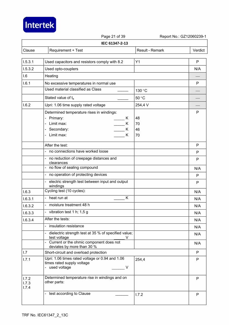
I.5.3.1 Used capacitors and resistors comply with 8.2 Y1 P
I.5.3.2 Used opto-couplers N/A
I.6 Heating ⎯
I.6.1 No excessive temperatures in normal use P
Used material classified as Class _____ 130 °C ⎯
Stated value of ta _____ 50 °C ⎯
I.6.2 Upri: 1.06 time supply rated voltage 254,4 V ⎯
Determined temperature rises in windings: - Primary: _____ K - Limit max: _____ K - Secondary: _____ K - Limit max: _____ K
48 70 46 70
P
After the test: P
- no connections have worked loose P
- no reduction of creepage distances and clearances
P
- no flow of sealing compound N/A
- no operation of protecting devices P
- electric strength test between input and output windings
P
I.6.3 Cycling test (10 cycles): N/A
I.6.3.1 - heat run at _____ K N/A
I.6.3.2 - moisture treatment 48 h N/A
I.6.3.3 - vibration test 1 h; 1,5 g N/A
I.6.3.4 After the tests: N/A
- insulation resistance N/A
- dielectric strength test at 35 % of specified value; test voltage _____ V
N/A
- Current or the ohmic component does not deviates by more than 30 %
N/A
I.7 Short-circuit and overload protection P
I.7.1 Upri: 1.06 times rated voltage or 0.94 and 1.06 times rated supply voltage - used voltage ______ V
254,4 P
I.7.2 I.7.3 I.7.4
Determined temperature rise in windings and on other parts:
P
- test according to Clause ______ I.7.2 P

Page 22 of 39 Report No.: GZ12060239-1
IEC 61347-2-13
Clause Requirement + Test Result - Remark Verdict
TRF No. IEC61347_2_13C
- Primary winding ______ K 0 P
- Limit max ______ K 125 P
- Secondary winding ______ K 0 P
- Limit max ______ K 125 P
- External enclosure ______ K 0 P
- Limit max K 55 P
- PVC insulation of input wiring ______ K 0 P
- Limit max K 35 P
- PVC insulation of output wiring ______ K 0 P
- Limit max K 35 P
- Supports ______ K 0 P
- Limit max K 55 P
I.7.5 Fail-safe convertors N/A
I.7.5.1 - Upri: 1.06 times rated supply voltage ............... V: ⎯
- Isec: 1.5 times rated output current ................. A: ⎯
- time until steady-state conditions t1 (h) .............. : ⎯
- time until failure t2 (h): < t1; < 5 h ....................... : N/A
I.7.5.2 During the test: N/A
- no flames, molten material, etc. N/A
- temperature rise of enclosure < 150 K N/A
- temperature rise of plywood support < 100 K N/A
After the test: N/A
- electric strength (test voltage; 35 % of specified value); no flashover or breakdown for primary-to-secondary and for primary-to-body
N/A
- live parts not accessible by test finger through holes of enclosure
N/A
I.8 Insulation resistance and electric strength P
I.8.1 Conditioned 48 h between 91 % and 95 % P
I.8.2 Adequate insulation (500 V d.c. for 1 min) between: P
Live parts and the body -for basic insulation not less than 2 MΩ ....................................................... :
N/A
Live parts and the body -for reinforced insulation not less than 4 MΩ ................................................. :
>100 MΩ P
Input- and output circuits not less than 5 MΩ ........ : >100 MΩ P
Metal parts of class II controlgear which are separated from live parts by basic insulation only and the body not less than 5 MΩ ........................... :
N/A

Page 23 of 39 Report No.: GZ12060239-1
IEC 61347-2-13
Clause Requirement + Test Result - Remark Verdict
TRF No. IEC61347_2_13C
Metal foil in contact with the inner and outer surfaces of enclosures of insulating material not less than 2 MΩ ....................................................... :
>100 MΩ P
I.8.3 Electric strength test: P
1) Between live parts of input circuits and live parts of output circuits ................................................. :
3750 V P
2) Over basic or supplementary insulation between: P
a) live parts which are or may become of different polarity ................................................................ :
1875 V P
b) live parts and body if intended to be connected to protective earth .................................................. :
N/A
c) accessible metal parts and a metal rod of the same diameter as the flexible cable or cord ...... :
N/A
d) live parts and an intermediate metal part ........... : N/A
e) intermediate metal parts and the body .............. : N/A
3) Over reinforced insulation between the body and live parts ............................................................. :
3750 V P
No flashover or breakdown occurred P
I.9 Construction P
I.9.1 Comply with all requirements P
I.9.2 The distance between input and output terminals shall not be less than 25 mm ................................. :
48 mm P
I.10 Components N/A
I.10.1 Socket-outlets in the output circuit does not accept plugs complying with IEC 60083 and IEC 60906-1
N/A
I.10.2 Self-resetting protective devices shall not be used unless it is certain that there will be no hazards
N/A
Compliance is checked by connecting the controlgear for 48 h at 1.06 times the rated voltage with the output short-circuited
N/A
I.11 Creepage distances and clearances P
1. Insulation between input and output circuits: P
a) measured values > specified values (mm) ........ : Between component of primary circuit and secondary circuit: >=6,1 mm (limited: 6,0 mm);
P
b) measured values > specified values (mm) ........ : N/A
c) measured values > specified values (mm) ........ : Certificated reinforce insulation winding as secondary winding; Three layers insulation tapes: 0,12 mm thickness (limited: 0,1 mm)
P
2. Insulation between adjacent input circuits: measured values > specified values (mm) ........ :
N/A
2. Insulation between adjacent output circuits: measured values > specified values (mm) ........ :
N/A

Page 24 of 39 Report No.: GZ12060239-1
IEC 61347-2-13
Clause Requirement + Test Result - Remark Verdict
TRF No. IEC61347_2_13C
3. Insulation between terminals for external connection: N/A
a) measured values > specified values (mm) ........ : N/A
b) measured values > specified values (mm) ......... : N/A
c) measured values > specified values (mm) ........ : N/A
4. Basic or supplementary insulation: N/A
a) measured values > specified values (mm) ........ : Fuse resistor N/A
b) measured values > specified values (mm) ........ : N/A
c) measured values > specified values (mm) ........ : N/A
5. Reinforced insulation: measured values > specified values (mm) ........................................ :
live parts and the enclosure: >= 6,1 mm (limit: 6,0 mm)
P
6. Distance through insulation: P
a) measured values > specified values (mm) ........ : N/A
b) measured values > specified values (mm) ......... : live parts separated by enclosure (reinforced insulation): >= 1,5 mm (limit: 1,0 mm)
P
c) measured values > specified values (mm) ........ : N/A
d) measured values > specified values (mm) ........ : N/A
Page 28 of 39 Report No.: GZ12060239-1
IEC 61347-2-13
Clause Requirement + Test Result - Remark Verdict
TRF No. IEC61347_2_13C
ANNEX 2: screw terminals (part of the controlgear) N/A
(14) SCREW TERMINALS N/A
ANNEX 3: screwless terminals (part of the controlgear) N/A
(15) SCREWLESS TERMINALS N/A

Page 29 of 39 Report No.: GZ12060239-1
IEC 61347-2-13
Clause Requirement + Test Result - Remark Verdict
TRF No. IEC61347_2_13C
Appendix of TRF No.: IEC61347_2_13C
CENELEC COMMON MODIFICATIONS (EN) P
16 (16) TABLE: creepage distances and clearances P
Minimum distances for a.c. (50/60 Hz) sinusoidal voltages P
RMS working voltage (V) not exceeding 50 150 250 500 750 1000
1 between live parts of different polarity -- N/A 6,0 mm -- -- --
2 between live parts and accessible metal parts which are permanently fixed to the ballast, including screws or devices for fixing covers or fixing the ballast to its support
-- >= 6,1 mm
>= 6,1 mm
-- -- --
3 for ballasts declared not to rely on the luminaire enclosure for protection against electric shock –between live parts and outer accessible surface of insulating parts
-- >= 6,1 mm
>= 6,1 mm
-- -- --
PTI≥600 0,6 0,8 1,5 3 4 5,5 Basic insulation
PTI<600 1,2 1,6 2,5 5 8 10
PTI≥600 -- 0,8 1,5 3 4 5,5 Supplementary insulation PTI<600 -- 1,6 2,5 5 8 10
Creepage distances
Reinforced insulation -- 3,2 5 6 8 11
Basic insulation 0,2 0,8 1,5 3 4 5,5
Supplementary insulation -- 0,8 1,5 3 4 5,5 Clearances
Reinforced insulation -- 1,6 3 6 8 11
Page 30 of 39 Report No.: GZ12060239-1
IEC 61347-2-13
Clause Requirement + Test Result - Remark Verdict
TRF No. IEC61347_2_13C
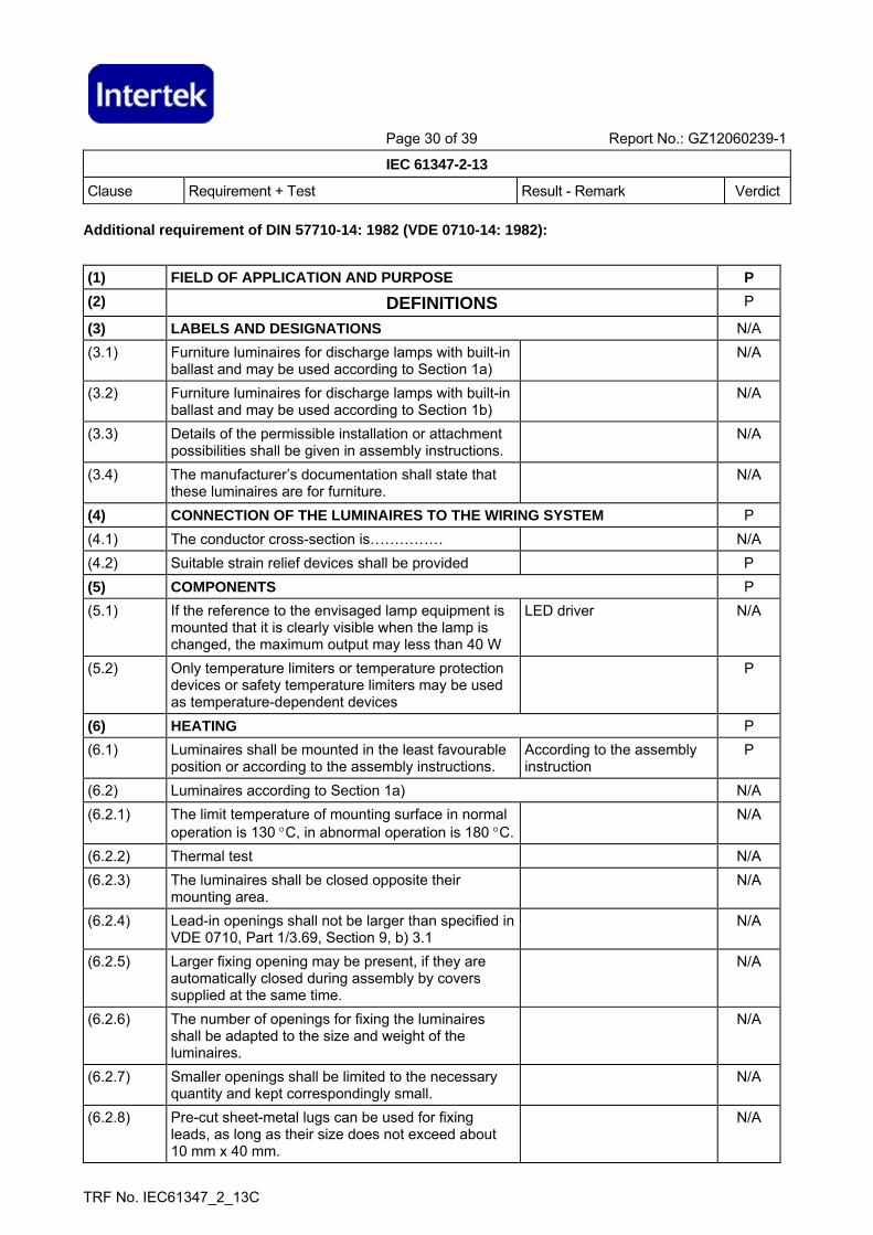
Additional requirement of DIN 57710-14: 1982 (VDE 0710-14: 1982):
(1) FIELD OF APPLICATION AND PURPOSE P (2) DEFINITIONS P
(3) LABELS AND DESIGNATIONS N/A (3.1) Furniture luminaires for discharge lamps with built-in
ballast and may be used according to Section 1a) N/A
(3.2) Furniture luminaires for discharge lamps with built-in ballast and may be used according to Section 1b)
N/A
(3.3) Details of the permissible installation or attachment possibilities shall be given in assembly instructions.
N/A
(3.4) The manufacturer’s documentation shall state that these luminaires are for furniture.
N/A
(4) CONNECTION OF THE LUMINAIRES TO THE WIRING SYSTEM P (4.1) The conductor cross-section is…………… N/A (4.2) Suitable strain relief devices shall be provided P (5) COMPONENTS P (5.1) If the reference to the envisaged lamp equipment is
mounted that it is clearly visible when the lamp is changed, the maximum output may less than 40 W
LED driver N/A
(5.2) Only temperature limiters or temperature protection devices or safety temperature limiters may be used as temperature-dependent devices
P
(6) HEATING P (6.1) Luminaires shall be mounted in the least favourable
position or according to the assembly instructions. According to the assembly instruction
P
(6.2) Luminaires according to Section 1a) N/A (6.2.1) The limit temperature of mounting surface in normal
operation is 130 °C, in abnormal operation is 180 °C. N/A
(6.2.2) Thermal test N/A (6.2.3) The luminaires shall be closed opposite their
mounting area. N/A
(6.2.4) Lead-in openings shall not be larger than specified in VDE 0710, Part 1/3.69, Section 9, b) 3.1
N/A
(6.2.5) Larger fixing opening may be present, if they are automatically closed during assembly by covers supplied at the same time.
N/A
(6.2.6) The number of openings for fixing the luminaires shall be adapted to the size and weight of the luminaires.
N/A
(6.2.7) Smaller openings shall be limited to the necessary quantity and kept correspondingly small.
N/A
(6.2.8) Pre-cut sheet-metal lugs can be used for fixing leads, as long as their size does not exceed about 10 mm x 40 mm.
N/A

Page 31 of 39 Report No.: GZ12060239-1
IEC 61347-2-13
Clause Requirement + Test Result - Remark Verdict
TRF No. IEC61347_2_13C
(6.2.9) Pre-punched openings closed when the luminaire is new shall likewise be permissible, insofar as they are not within the ballast area.
N/A
(6.2.10) Opening other than those so far specified may be face the mounting area only if they are closed by covers which can be removed only by a tool.
N/A
(6.3) Luminaires according to Section 1b), the mounting surface shall not exceed 95 °C
P
(6.3.1) The mounting surface shall not exceed 115 °C during normal and abnormal operation with 1,1 Un
76 °C P
(6.3.2) Determination of the temperatures during abnormal operation and in the case of a ballast fault.
P
(6.3.2.1) Luminaires without temperature-limiting devices. N/A (6.3.2.2) Luminaires with temperature-limiting devices. P (6.4) In the case of luminaires in which exceeding of the
limit value is prevented by temperature-dependent devices, it shall be proved by the following test that disconnection takes place before or on attainment of the specified limit values. The limit is 180 °C for the luminaires according to 1a), 115 °C for the luminaires according to 1b).
85 °C P
(7) CORROSION RESISTANCE N/A (7.1) The test according to VDE 0710, Part 1/3.69,
Section 19. N/A
(8) REPAIR OF LUMINAIRE N/A Only DIN 57701, Part 1/VDE 0701, Part 1 shall apply
to the repair of luminaires in VDE 0710, Part 1/3.69, Section 21.
N/A

Page 32 of 39 Report No.: GZ12060239-1
IEC 61347-2-13
Appendix I: model list
TRF No. IEC61347_2_13C