IEA Bioenergy Task 34: Direct Thermochemical Lique...
24
Canadian perspectives on typical subjects, such as bioenergy production, biorefining, supply chain, policy drivers, and snapshots of the frontiers of commercialization. It included a Direct Thermochemical Liquefaction session entitled Technology Commercialization – Achieving Success in Pyrolysis, Cellulosics, Hydrothermal Liquefaction, and Hydrofaction™ for Long-haul Transport. Yet there were also unusually fascinating panels on banking and financing, communication and collaboration, raising capital, and sourcing new research talent. Hidden gems included impassioned requests from environmental regulators for help in overcoming permitting and compliance barriers that are currently slowing adoption of some bioenergy. This event was opportunity to see the collaboration of technologists and CEOs, bankers and regulators, which is needed for successful bionenergy. What of the biomass used by Canada, Sweden, and New Zealand? It’s no surprise that these countries share a common interest in bioenergy and bioproducts: the cold Inside this Issue: Pg 3: Axel Funke compares intermediate and fast pyrolysis bio-oils from multiple biomass types fed to screw-type reactors. Pg 6: Charles Mullen describes production and isolation of catalytic fast pyrolysis co-products, such as methoxy- & alkyl- phenols Pg 8: Marjorie Rover demonstrates applications for phenolic oils from pyrolysis: hydrotreating, solid fuel, and asphalt binder. Pg 11: Bert van de Beld runs a 4-cylinder diesel engine on fast pyrolysis bio-oil, describing the modifications to achieve success. Pg 14: Yaseen Elkasabi discusses the composition and potential for biorenewable calcined coke as a co-product from pyrolysis. Pg 16: Robert Brown captures ISU’s progress on operation of continuous solvent liquefaction and product fractionation systems. Pg 19: Steve Rogers introduces the Licella and their progress on commercialization of the Catalytic Hydrothermal Reactor Pg 22: Paul de Wild gives an update on the PYRENA reactor, its progress, and considerations for catalytic pyrolysis and upgrading. What do Canada, Sweden, and New Zealand have in common? All three are producing bioenergy and bioproducts from the same biomass, proving it can be grown sustainably over decades and generations. It occurred to me arriving in Ottawa, Canada, for the Task 34 meeting held in November alongside Bioenergy for the Future, where the IEA announced the new “Technology Roadmap: Delivering Sustainable Bioenergy”, and Scaling Up 2017, an inspiring event highlighting the immediate need for scaled-up bioenergy. Scaling Up was a uniquely refreshing experience, driven exclusively by topic centered Q&A panels with limited introductory remarks. The format breathed life into dynamic discussions of differing perspectives on a range of issues crucial to getting biofuels and bioenergy into the market, with hard questions from the audience generating interesting debate. Topics included both global and Demonstrating sustainable bioenergy…and Scaling it up Fig. 1: Biomass production and fuel storage in Sweden destined for transport diesel fuel. December 2017 Task 34: Direct Thermochemical Liquefaction IEA Bioenergy For more info: [email protected] or task34.ieabioenergy.com/
Transcript of IEA Bioenergy Task 34: Direct Thermochemical Lique...

Canadian perspectives on typical
subjects, such as bioenergy
production, biorefining, supply chain,
policy drivers, and snapshots of the
frontiers of commercialization. It
included a Direct Thermochemical
Liquefaction session entitled
Technology Commercialization –
Achieving Success in Pyrolysis,
Cellulosics, Hydrothermal
Liquefaction, and Hydrofaction™ for
Long-haul Transport.
Yet there were also unusually
fascinating panels on banking and
financing, communication and
collaboration, raising capital, and
sourcing new research talent. Hidden
gems included impassioned requests
from environmental regulators for help
in overcoming permitting and
compliance barriers that are currently
slowing adoption of some bioenergy.
This event was opportunity to see the
collaboration of technologists and
CEOs, bankers and regulators, which
is needed for successful bionenergy.
What of the biomass used by
Canada, Sweden, and New
Zealand? It’s no surprise that these
countries share a common interest in
bioenergy and bioproducts: the cold
Inside this Issue: Pg 3: Axel Funke compares intermediate and fast pyrolysis bio-oils from multiple biomass types fed to screw-type reactors.
Pg 6: Charles Mullen describes production and isolation of catalytic fast pyrolysis co-products, such as methoxy- & alkyl- phenols
Pg 8: Marjorie Rover demonstrates applications for phenolic oils from pyrolysis: hydrotreating, solid fuel, and asphalt binder.
Pg 11: Bert van de Beld runs a 4-cylinder diesel engine on fast pyrolysis bio-oil, describing the modifications to achieve success.
Pg 14: Yaseen Elkasabi discusses the composition and potential for biorenewable calcined coke as a co-product from pyrolysis.
Pg 16: Robert Brown captures ISU’s progress on operation of continuous solvent liquefaction and product fractionation systems.
Pg 19: Steve Rogers introduces the Licella and their progress on commercialization of the Catalytic Hydrothermal Reactor
Pg 22: Paul de Wild gives an update on the PYRENA reactor, its progress, and considerations for catalytic pyrolysis and upgrading.
What do Canada, Sweden, and New
Zealand have in common? All three
are producing bioenergy and
bioproducts from the same biomass,
proving it can be grown sustainably
over decades and generations.
It occurred to me arriving in Ottawa,
Canada, for the Task 34 meeting held
in November alongside Bioenergy for
the Future, where the IEA announced
the new “Technology Roadmap:
Delivering Sustainable Bioenergy”,
and Scaling Up 2017, an inspiring
event highlighting the immediate need
for scaled-up bioenergy.
Scaling Up was a uniquely refreshing
experience, driven exclusively by topic
centered Q&A panels with limited
introductory remarks. The format
breathed life into dynamic discussions
of differing perspectives on a range of
issues crucial to getting biofuels and
bioenergy into the market, with hard
questions from the audience
generating interesting debate.
Topics included both global and
Demonstrating sustainable bioenergy…and Scaling it up
Fig. 1: Biomass production and fuel
storage in Sweden destined for
transport diesel fuel.
December 2017
Task 34: Direct Thermochemical Liquefaction IEA Bioenergy
For
mo
re in
fo: P
yN
eE
dito
r@g
ma
il.co
m
o
r ta
sk3
4.ie
ab
ioe
ne
rgy.c
om
/

PyNe 41, IEA Bioenergy Task 34 Page 2 of 24
products are starting to displace
petroleum use. In Sweden, Preem is
making diesel fuel from tall oil and
looking to advanced technology. In
Canada, Ensyn is actively delivering
pyrolysis oil to heat commercial
buildings. In New Zealand, Scion is
developing packaging material,
expanded foams, and bio-plastics from
wood sourced materials.
While there is no one-size-fits-all
solution to our international energy
needs, it is clear that sustainably
managed forestry products are
already filling an important role in both
renewable bioenergy and bioproducts.
And with a decades of evidence that it
can be managed sustainably, it will
certainly contribute for years to come.
. – Alan Zacher, Task 34 US NTL
Members of IEA
Bioenergy Task 34:
2016-2018
Netherlands
Bert van de Beld BTG Biomass Technology Group BV Josink Esweg 34 7545 PN, NETHERLANDS T: +31 53 486 1186 E: [email protected] New Zealand
Ferran de Miguel Mercader Scion, 49 Sala Street, Private Bag 3020 Rotorua 3046, NEW ZEALAND T: +64 7 343 5331 E: [email protected] Sweden
Magnus Marklund SP Energy Technology Industrigatan 1, 941 38 Piteå, SWEDEN T: +46 911 23 23 85 E: [email protected] USA
Alan Zacher (Task 34 Team Leader) Pacific Northwest National Laboratory (PNNL) 902 Battelle Boulevard, PO Box 999, Richland, Washington, 99352 USA T: +1 509 372 4545 El: [email protected]
Canada
Fernando Preto CanmetENERGY, Natural Resources Canada 1 Haanel Drive, Ottawa, CANADA K1A 1M1 T: +1 613 769 6259 E:[email protected] Finland
Kristin Onarheim VTT Technical Research Centre of Finland Ltd Tekniikankatu 1, TAMPERE, P.O. Box 1300, FI-33101 TAMPERE, Finland T: +358 040 176 3129 E: [email protected] Germany
Nicolaus Dahmen Karlsruhe Institute of Technology (KIT) Hermann-von-Helmholtz-Platz 1, D-76344 Eggenstein-Leopoldshafen, GERMANY T: +49 721 608 22596 E:[email protected]
climate of Canada and Sweden, and
the location of New Zealand make
these needs imperative. Yet I hadn’t
realized that all three countries were
also world leaders in sustainably
managing forests towards that goal.
It is easy to mistake a tree for a
consumable in the short term. One day
it is there, the next day it is not. Yet a
tree may be just another energy and
product crop if your farming
perspective covers multiple decade
investments.
Swedes, Canadians, and New
Zealanders do this today. Seedlings
planted today will have full impact in
20, 30, 50 years. So, in New Zealand,
they forecast wood tonnage yields
every year in 20-30 year horizons. In
Sweden and Canada, where growing
cycles are slower, those yield
Demonstrating sustainable bioenergy…continued
forecasts stretch out to 50 or more
years
Historically, these countries have
sustainably farmed and harvested
these natural resources for decades,
and in some cases hundreds, of years.
The difference is that today, their
Fig. 2: Pyrolysis oil combustion.

PyNe 41, IEA Bioenergy Task 34
Page 3 of 24
Water (ar) Ash (d) C (d) H (d) O* (d) HHV (d) Volatiles (d) (%) (%) (%) (%) (%) (kJ g-1) (%)
Beech wood 9.0 1.2 49.6 6.0 42.5 18.7 83.1 Poplar wood 7.8 2.0 48.9 5.9 43.2 18.7 82.1 Blend 7.0 4.0 47.7 5.8 42.5 18.6 77.3 Wheat straw 5.7 12.9 42.8 5.4 38.9 16.6 67.0
which reflects the temperature of secondary vapour phase reactions and also the mixing temperature of heat carrier/biomass particles in case of fast pyrolysis. The feed rate was in the same range and limited by the material with the lowest volumetric density (wheat straw). The condensation strategy of the two test rigs has been adapted for the specific products and shows significant differences. Final condensation temperature was kept as close as possible with the existing equipment so that the overall bio-oil yield (and its components) can be compared directly. A comparison of the bio-oil quality was not aim of this study and requires alignment of the
presented here have been supplied for analysis within this Round Robin (Elliott et al., 2017). The intention was to establish a broader context to compare bio-oil yields. Unfortunately, the results of aforementioned Round Robin have finally been published without an indication of bio-oils yields from the different laboratories. In addition to these three feedstocks, beech wood was chosen as one of the few biomass resources that are commercially available with a relevant quality control (particle size, ash content, bulk density, moisture content). Analyses of these feedstocks are summarized in Table 1. It is pointed out that the ash
actually quantify the differences in yields from intermediate and fast pyrolysis, which both aim at producing a bio-oil as main product.
The aim of the present study is to close this gap by comparing the product distribution of two pilot scale pyrolysis units with 10 kg h-1 feed capacity that are operated with intermediate and fast pyrolysis conditions for the same set of biomass (Funke et al., 2017). The type of biomass used was beech wood, hybrid poplar wood, wheat straw, and a blend (hybrid poplar, forest thinnings, wheat straw). The latter three feedstocks have been supplied as part of a Round Robin organized by the IEA Bioenergy Task 34 and the bio-oils obtained from the fast pyrolysis trials
Intermediate pyrolysis is a well investigated process with distinct differences to the commonly known slow and fast pyrolysis. Its primary aim is to produce a liquid product with transportation fuel quality (Neumann et al., 2015; Tomasi Morgano et al., 2015). It operates at a solid residence time of minutes rather than hours, as for the case of slow pyrolysis, or seconds, as for the case of fast pyrolysis. The biomass particles are heated with a heating rate of around 100 K min-1, which is orders of magnitude below that of fast pyrolysis. Another important characteristic is the vapour residence time at reactor temperature. In contrast to fast pyrolysis, secondary pyrolysis reactions of the vapour products are allowed or even promoted with special reforming steps. It is obvious and well-known that these operating conditions lead to a lower bio-oil and higher reaction water yield. This price of low yields is paid to obtain a bio-oil product that shows more favourable characteristics as a transportation fuel than typical fast pyrolysis bio-oil (Neumann et al., 2015). It is interesting to note that to date there was no concerted effort to
Comparison of intermediate and fast pyrolysis in screw-type reactors
Axel Funke Pending Karlsruhe Institute of Technology (KIT)
(Continued on page 4)
Table 1: Analyses of the selected feedstocks.
* by difference; ar: as received;, d: dry
content covers a broad range between 1-13 % (dry mass basis) The setup of the test rigs and general experimental procedures are described in detail elsewhere (Funke et al., 2016; Tomasi Morgano et al., 2015). Both test rigs incorporate screw type reactors. High heat transfer for fast pyrolysis conditions is achieved by adding a preheated heat carrier to the reactor, which is then mechanically mixed with the feedstock by two interlacing screws. The process conditions have been chosen to both reflect the different intermediate/fast pyrolysis process conditions and at the same time be as close as possible for comparison (see Table 2). They do not necessarily reflect optimum process conditions. Reactor temperature was controlled closely at the same level,

PyNe 41, IEA Bioenergy Task 34 Page 4 of 24
51.249
35.6
25.6
21.123.1
18.4 16.7
0
10
20
30
40
50
60
Beech wood Poplar wood Blend Wheat straw
Yie
ld, d
ry f
ee
dst
ock
mas
s b
asis
(%
)
Organic liquid (FP)
Organic liquid (IP)
Water of reaction (FP)
Water of reaction (IP)
Dur. Feed rate Rxtr. temp.
Heating rate Vapour res. time
Condens. temp(s)
Python 4-5 h 5-6 kg h-1 500°C >10.000 K min-1 <4 s 90°C; 20°C STYX 3-4 h 3 kg h-1 500°C ≈100 K min-1 <20 s 80°C; 15°C
Comparison of pyrolysis in screw-type reactors…Continued
…continued
(Continued on page 5)
Table 2: Process conditions of the experiments
condensation strategies to allow for a feasible data basis.
Screw-type reactors have been questioned to be representative for fast pyrolysis (Elliott et al., 2017). This hypothesis can be investigated with the present study because fast pyrolysis experiments have been conducted as part of the IEA Bioenergy Task 34 Round Robin and also because beech wood has been used additionally. The most meaningful basis to compare bio-oil yields is on the basis of the organic liquid yield, which excludes the water content of liquid product(s) (see Figure 1). The organic liquid yield obtained in this study from beech wood fast pyrolysis is comparable to the range of 50-55 % reported elsewhere for beech wood (Beaumont & Schwob, 1984; Greenhalf et al., 2013). Unfortunately, results in literature are often only reported for the bio-oil yield, i.e. including water. Such data for beech wood fast pyrolysis reports bio-oil yields of around 61-70 % (Beaumont & Schwob, 1984; Di Blasi & Branca, 2001; Jendoubi et al., 2011; Wang et al., 2005). These
for subsequent gasification (Dahmen et al., 2012; Nicoleit et al., 2016).
Obviously, the reactor type used to achieve fast pyrolysis conditions is of minor importance as long as heating rate and hot vapour residence time requirements are met. It is concluded that the screw-type reactor used in this study is suitable to achieve all necessary fast pyrolysis conditions and in consequence to produce a ‘typical’ fast pyrolysis bio-oil. All data indicate that it is a suitable representative for fast pyrolysis to allow for a comparison with intermediate pyrolysis.
The organic liquid yields obtained from fast pyrolysis are significantly higher than from intermediate pyrolysis, as expected. It is
results are in line with bio-oil yields obtained from beech wood fast pyrolysis in the present study, too (69.9±0.9 %).
Finally, the quality of the produced fast pyrolysis bio-oil from the feedstocks supplied by the IEA Bioenergy Task 34 Round Robin does not show a significant deviation from bio-oils produced by fluidized bed or ablative reactors (Elliott et al., 2017). Values can be easily checked because there has been only one participating laboratory that applied a twin-screw technology. The only exception to the quality parameters is the high solids content. The comparably poor solid separation prior to condensation is due to the current project requirements in which the condensate(s) are mixed with the solids to produce a bioslurry
Figure 1: Organic liquid and water of reaction yields (FP: fast pyrolysis, IP: intermediate pyrolysis). Error bars indicate the difference between two experimental runs.

PyNe 41, IEA Bioenergy Task 34
Page 5 of 24
interesting to observe that the yields
from fast pyrolysis are more heavily affected by the ash content of the feedstock. While more than twice as much organic liquid is produced in case of beech wood only 50 % more is produced for the ash-rich wheat straw. Consequently, the advantage of high organic liquid yields has to be evaluated with special consideration of the type of feedstock used. The high amount of reaction water produced during intermediate pyrolysis does not affect bio-oil quality negatively. Water content in the intermediate pyrolysis bio-oil of around 10 % has been observed with the current condensation and product recovery design.
The yield of several marker species has been evaluated for the obtained bio-oils. The results support the expected ongoing pyrolytic reactions in case of intermediate pyrolysis. Acetic acid yields are increased and so is the yield of phenol on the expense of guaiacol. It can even be observed that benzene and naphthalene are produced with yields one order of magnitude higher than for fast pyrolysis.
Surely, this study is a first step to allow for a more detailed comparison of these two pyrolysis technologies. It provides the required quantitative data to show differences in product distribution. The next step is to directly compare bio-oil quality and relate it to the differences in bio-oil yield. Such data is a mandatory prerequisite to allow for a rational decision for suitable pyrolysis technology dependent on feedstock and product use.
Comparison of pyrolysis in screw-type reactors…Continued
…continued References
Beaumont, O., Schwob, Y. 1984. Influence of Physical and Chemical Parameters on Wood Pyrolysis. Ind Eng Chem Process Des Dev, 23, 637-641.
Dahmen, N., Henrich, E., Dinjus, E., Weirich, F. 2012. The bioliq bioslurry gasification process for the production of biosynfuels, organic chemicals, and energy. Energ Sust Soc, 2(3).
Di Blasi, C., Branca, C. 2001. Kinetics of Primary Product Formation from Wood Pyrolysis. Ind Eng Chem Res, 40(23), 5547-5556.
Elliott, D.C., Meier, D., Oasmaa, A., van de Beld, B., Bridgwater, A.V., Marklund, M. 2017. Results of the International Energy Agency Round Robin on Fast Pyrolysis Bio-oil Production. Energ Fuel, 31(5), 5111-5119.
Funke, A., Richter, D., Niebel, A., Dahmen, N., Sauer, J. 2016. Fast Pyrolysis of Biomass Residues in a Twin-screw Mixing Reactor. J Vis Exp, 115, e54395.
Funke, A., Tomasi Morgano, M., Leibold, H., Dahmen, N. 2017. Experimental Comparison of Fast and Intermediate Pyrolysis. J Anal Appl Pyr, 124, 504-514.
Greenhalf, C.E., Nowakowski, D.J., Harms, A.B., Titiloye, J.O., Bridgwater, A.V. 2013. A comparative study of straw, perennial grasses and hardwoods in terms of fast pyrolysis products. Fuel, 108, 216-230.
Jendoubi, N., Broust, F., Commandre, J.M., Mauviel, G., Sardin, M., Lede, J. 2011. Inorganics distribution in bio oils and char produced by biomass fast pyrolysis: The key role of aerosols. J Anal Appl Pyr, 92(1), 59-67.
Neumann, J., Binder, S., Apfelbacher, A., Gasson, J.R., Ramírez García, P., Hornung, A. 2015. Production and characterization of a new quality pyrolysis oil, char and syngas from
digestate - Introducing the thermo-catalytic reforming process. Journal of Analytical and Applied Pyrolysis, 113, 137-142.
Nicoleit, T., Dahmen, N., Sauer, J. 2016. Production and Storage of Gasifiable Slurries Based on Flash-Pyrolyzed Straw. Energy Technology, 4(1), 221-229.
Tomasi Morgano, M., Leibold, H., Richter, F., Seifert, H. 2015. Screw pyrolysis with integrated sequential hot gas filtration. Journal of Analytical and Applied Pyrolysis, 113, 216-224.
Wang, X., Kersten, S., Prins, W., van Swaaij, W.P.M. 2005. Biomass Pyrolysis in a Fluidized Bed Reactor. Part 2: Experimental Validation of Model Results. Ind Eng Chem Res, 44, 8786-8795.
Contact:
Dr.-Ing. Axel Funke Fast Pyrolysis Group Hermann-von-Helmholtz-Platz 1 Building 727 76344 Eggenstein-Leopoldshafen, Germany Phone: +49 721 608-22391 Fax: +49 721 608-22244 Email: [email protected] Web: http://www.kit.edu/

PyNe 41, IEA Bioenergy Task 34 Page 6 of 24
Much of the research in biomass
pyrolysis over the last decade has
focused on modifications to the
pyrolysis process to produce stable,
partially deoxygenated bio-oils. This
has been done, usually, with the
ultimate goal of reducing the oxygen
content, after upgrading, to near zero
for use in advanced hydrocarbon bio-
fuels. However, there is now a
realization that to be commercially
viable, biorefineries will need to
produce high value chemical or
materials co-products in addition to
fuels, just as petroleum refineries do.
This is where preservation of some of
the inherent oxygen content, that we
have long sought to remove, may be an
advantage. Nearly limitless useful
oxygenated chemicals, from high
volume commodities to premium
pharmaceutical precursors are
produced through oxidation of
petroleum hydrocarbons, so
oxygenated biomass derived
replacements may be advantageous.
USDA-ARS has begun researching
ways to increase the yield of certain
targeted oxygenated hydrocarbons
during pyrolysis and also isolate them
from the complex mixture. One
examples is phenolics. The phenolic
aromatic C-O bond is among the most
difficult of all the C-O bonds found in
bio-oils to break, and phenols are found
Increasing production and isolation of phenols via pyrolysis of lignocellulosic biomass
reason, we sought to understand the
properties of these partially deactivated
zeolites, and mimic them to maximize
production of alkyl phenols. Catalyst
deactivation can occur by deposition of
carbon deposits on catalysts or by
poisoning by alkali metals; both of
these have the effect of decreasing the
Brønsted acid site density. We
therefore produced a simple series of
catalysts, reducing the acid site density
by exchanging the acid sites with
potassium (K).
As shown in Figure 1, when the KZSM-
5 catalyst was used for the CFP of
switchgrass, there was a 74% decrease
in the production of aromatic
hydrocarbons compounds and ~3-fold
increase in the production of the
selected alkyl- and methoxy phenols
compared to the parent HZSM-5. In
the case of methoxy phenols, the yield
was lower than that achieved non-
catalytically, which suggests they were
not formed catalytically but rather their
Charles Mullen USDA-ARS
Figure 1. Comparison of yields from selected compounds from switchgrass (SWG) and Cellulose (Cell) over HZSM-5 (23) and KZSM-5 (23) at 5/1 catalyst/biomass and 500 ºC. Alkyl phenols = phenol, o-,m-,p-cresols, 2,4-dimethyl phenol and 4-ethyl phenol. Methoxy phenols = guaiacol, 4-methylguaiacol, syringol. BTEX = benzene, toluene, ethyl benzene, xylenes. Error bars represent one standard deviation.
among the remaining oxygenates in
both the CFP and TGRP processes.
Furthermore, phenol is more valuable
than its completely deoxygenated
analog benzene. For these reasons
phenols are among the first oxygenated
chemicals we are targeting for
increased production during pyrolysis.
Two types of phenols are produced
from pyrolysis of lignocellulosic
biomass, alkyl phenols which can be
derived from either the cellulose or
lignin polymer, and methoxylated
phenols which are generated directly
from lignin depolymerization. Recent
developments in our laboratory have
increased the production of both
classes of phenols from pyrolysis of
biomass. In many studies of HZSM-5
zeolite catalyst deactivation, alkyl
phenols are often found as an
“intermediate” product, not produced by
fresh catalysts, but by partially
deactivated catalysts at levels well
above non-catalytic pyrolysis. For this
(Continued on page 5)

PyNe 41, IEA Bioenergy Task 34
Page 7 of 24
Eqs. of 1,4-Butanediol added - 0.125 0.250 0.500 1.000
Bio-oil Yield 30.4 37.8 40.1 39.7 44.3
Bio-oil Mw 1187.9 637.6 443.4 332.0 134.9
Bio-oil Mn 350.5 261.8 221.9 181.3 102.7
Bio-oil PDI 3.39 2.44 2.00 1.83 1.31
Methoxy-phenols selectivity(wt%) 5 9 31 55 62
Alkyl-phenols selectivity (wt%) 95 91 69 45 38
catalytic conversion to other products
was limited by the use of a less active
catalyst. However, the alkyl phenol
yield was substantially higher (>4-fold
increase) than that produced non-
catalytically, meaning the alkyl phenols
were the product of a catalytic reaction,
not merely a consequence of
diminished catalytic conversion.
Similarly, there was an increase in the
production of furans, particularly 2-,
whose production increased to a yield
of 4.6 mg/g, whereas only trace
may help lead to the development of
novel lignin co-processing methods.
We believe that the addition of the diol
may quench radical or acid initiated
reploymerization reactions leading to
the observed higher yield and lower
molecular weight, and also that
preservation of the methoxy groups
may also decrease the occurrence of
repolyemrization reactions during
pyrolysis. More details on this
development can be found in our recent
journal publication [2].
We are currently building off these
developments to further increase the
production of phenolics from cellulose,
lignin and biomass. This includes
development of catalysts more
selective for phenols, transfer of
operations to a continuous larger scale
process and development of methods
for the selective isolation of phenols
from bio-oil.
References
[1] Mullen, C.A., Tarves, P.C., Boateng,
A.A. Role of Potassium Exchange in
Catalytic Pyrolysis of Biomass over
ZSM-5: Formation of Alkyl phenols and
Furans. ACS Sustainable Chemistry
and Engineering, 5, 2154-2162. 2017.
[2] Tarves, P. C., Mullen, C.A., Strahan,
G. D., Boateng, A.A. Depolymerization
of Lignin via Co-pyrolysis with 1,4-
Butanediol in a Microwave Reactor.
ACS Sustainable Chemistry and
Engineering, 5, 988-994. 2017
Contact
Charles A. Mullen, PhD
Research Chemist
Sustainable Biofuels and Coproducts
Eastern Regional Research Center,
ARS, USDA
600 E. Mermaid Lane, Wyndmoor PA
19038 USA
+1-215-836-6916
decrease in the average molecular
weight of the bio-oil. Lignin is also the
most abundant natural source of
aromatic compounds in the biosphere,
which makes it an attractive renewable
feedstock for the production of biofuels,
commodity chemicals, and other value
added products. Unfortunately, limited
success has been achieved in
development of effective
depolymerization strategies to unlock
this potential.
amounts were observed for HZSM-5
(23) and non-catalytic pyrolysis.
When cellulose was used as the
starting material rather than
switchgrass, the same trend is
observed, and the production of alkyl
phenols from cellulose (not just lignin)
is verified. Selected alkyl phenols were
produced in a yield of about 9 mg/g
from cellulose over KZSM-5 (23),
compared with 3.8 mg/g over HZSM-5
(23) and only trace amounts non-
catalytically. Similarly, the yield of 2-
methyl furan increased to over 5 mg/g
over KZSM-5 (23), compared with ~1
mg/g using HZSM-5 (23). More details
of this work can be found in our recent
ACS Sustainable Chemistry and
Engineering publication [1].
Meanwhile, in another development in
our laboratory we have also found that
microwave co-pyrolysis of lignin with
high boiling diols can increase its net
depolymerization, resulting in an
increase in production of
methoxyphenols along with an overall
In our work, lab scale microwave
pyrolysis of lignin has been performed
and the liquid products obtained are
composed of smaller polymeric
components and moderate yields of
monomeric phenols. However, upon
the addition of 1,4-butanediol,
repolymerization reactions that limit the
yield of monomeric and other reduced
molecular weight products are inhibited.
As shown in Table 1, a 85-90%
reduction in the average molecular
weight of the liquid products was
observed concurrent to an overall
increase in liquid yield. At the
optimized ratio of 2:1 lignin to 1,4-
butanediol (w/w), the yield of selected
monomeric phenols increased three-
fold to ~3.4 wt% (based on feedstock),
while the yield of mono-aromatic
hydrocarbons decreased by
approximately 90%. The addition of the
diol co-reactant also led to a significant
shift in selectivity towards the
production of methoxy-phenols
(guaiacols, syringols) over non-
methoxylated alkyl-phenols (phenol,
cresols, etc.). The results obtained
Increasing production and isolation of phenols…continued
Table 1. Effect of adding 1,4-butandiol to lignin during microwave pyrolysis on bio-oil yield, molecular weight, dispersity index and phenolic selectivity.

PyNe 41, IEA Bioenergy Task 34 Page 8 of 24
Individual
Highlights:
Inside Story 2
Inside Story 3
Inside Story 4
Inside Story 5
Last Story 6
Fast pyrolysis of lignin results in a mixture of phenolic monomers and oligomers sometimes referred to as pyrolytic lignin although phenolic oil is a more accurate characterization. Iowa State University (ISU) has developed a fractionating recovery system that collects phenolic oil has part of a heavy ends fraction [1, 2]. A simple water extraction is able to separate the water-insoluble phenolic oil from water soluble sugars and anhydrosugars [3]. Phenolic oil presents 40-45% of the carbon content of the products of pyrolysis. Most of the aromatic content of the lignin is preserved. Its oxygen content is approximately 20-24%, much lower than that of the carbohydrate-derived products of pyrolysis, giving it an attractive heating value for production of fuels. However, it is extremely reactive in storage or during thermal processing, which can complicate its refining, although in some cases this reactivity can be exploited. This paper explores some options for upgrading phenolic oil into various products.
pressures. Due to the reactive nature of the phenolic oil, low-temperature, low-pressure hydrogenation (LTLP-H) was utilized to produce a stable, low viscosity product at high yields [4]. Low-temperature, low-pressure hydrogenation, which was performed at 21 °C and 1 bar pressure, resulted in high carbon yields: 98.2% to 98.7% for phenolic oils from corn stover and red oak, respectively. The viscosities of phenolic oil samples (measured at 60 °C) dropped dramatically after hydrogenation: cornstover fraction 1 decreased by 81% and fraction 2 decreased by 47%. Red oak fraction 2
Low-temperature, low-pressure hydrogenation The superficial similarities between petroleum and bio-oil have encouraged efforts to upgrade it in the same way as petroleum. Any facile comparison is overshadowed by the fact that petroleum contains non-polar hydrocarbons that are relatively stable, requiring elevated temperatures and pressures to encourage chemical transformations, whereas bio-oil consists of oxygenated organic compounds whose high degree of functionality makes them chemically reactive even at low temperatures and
Applications of Phenolic Oil Derived from Fast Pyrolysis
more severe hydrocracking, which reduces the molecular weight of heavy organic compounds. Cracking of phenolics clearly did not occur during LTLP-H. Further analytical testing suggested that viscosity thinning was the result of the self-solvation power of produced alcohol during hydrogenation.
heavy ends showed a more dramatic drop in viscosity, decreasing by 99%. This viscosity thinning after hydrogenation is in sharp contrast to the viscosity thickening observed by researchers who used higher temperatures and pressures to hydroprocess bio-oil. Viscosity reductions are usually associated with
Marjorie R. Rover Bioeconomy Institute Iowa State University
Fig. 1 - Gas chromatography simulated distillation (SimDist ASTM D2887) of hydrotreated phenolic oil utilizing sulfided CoMo and Ru-Pd catalysts. experimental runs.
(Continued on page 9)
PyNe 41, IEA Bioenergy Task 34
Page 9 of 24
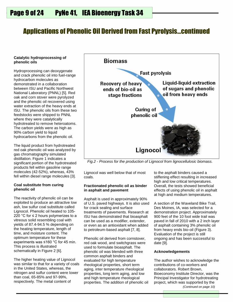
Catalytic hydroprocessing of phenolic oils Hydroprocessing can deoxygenate and crack phenolic oil into fuel-range hydrocarbon molecules as demonstrated in a collaboration between ISU and Pacific Northwest National Laboratory (PNNL) [5]. Red oak and corn stover were pyrolyzed and the phenolic oil recovered using water extraction of the heavy ends at ISU. The phenolic oils from these two feedstocks were shipped to PNNL where they were catalytically hydrotreated to remove heteroatoms. The carbon yields were as high as 90% carbon yield to liquid hydrocarbons from the phenolic oil. The liquid product from hydrotreated red oak phenolic oil was analyzed by gas chromatography simulated distillation. Figure 1 indicates a significant portion of the hydrotreated products fell within gasoline range molecules (42-52%), whereas, 43% fell within diesel range molecules [3]. Coal substitute from curing phenolic oil The reactivity of phenolic oil can be exploited to produce an attractive low ash, low sulfur coal substitute called Lignocol. Phenolic oil heated to 105-220 °C for ≤ 2 hours polymerizes to a vitreous solid resembling coal with yields of 87.4-94.5 % depending on the heating temperature, length of time, and moisture content. The optimum temperature for these experiments was ≤160 °C for 45 min. This process is illustrated schematically in Figure 2 [6]. The higher heating value of Lignocol was similar to that for a variety of coals in the United States, whereas, the nitrogen and sulfur content were lower than coal, 65-85% and 97-99%, respectively. The metal content of
to the asphalt binders caused a stiffening effect resulting in increased high and low critical temperatures. Overall, the tests showed beneficial effects of using phenolic oil in asphalt at high and medium temperatures. A section of the Waveland Bike Trail, Des Moines, IA, was selected for a demonstration project. Approximately 900 feet of the 10 foot wide trail was paved in fall of 2010 with a 2 inch layer of asphalt containing 3% phenolic oil from heavy ends bio-oil (Figure 3). Evaluation of the project is still ongoing and has been successful to date [9]. Acknowledgements The author wishes to acknowledge the contributions of co-workers and collaborators. Robert Brown, Bioeconomy Institute Director, was the Principal Investigator for hydrotreating project, which was supported by the
Lignocol was well below that of most coals. Fractionated phenolic oil as binder in asphalt and pavement Asphalt is used in approximately 90% of U.S. paved highways. It is also used for crack sealing and surface treatments of pavements. Research at ISU has demonstrated that bioasphalt can be used as a modifier, extender, or even as an antioxidant when added to petroleum-based asphalt [7, 8]. Phenolic oil derived from cornstover, red oak wood, and switchgrass were used to formulate bioasphalt. The phenolic oil was blended with three common asphalt binders and evaluated for high temperature rheological properties, short term aging, inter temperature rheological properties, long term aging, and low and high temperature rheological properties. The addition of phenolic oil
Fig.2 - Process for the production of Lignocol from lignocellulosic biomass.
Applications of Phenolic Oil Derived from Fast Pyrolysis…continued
(Continued on page 10)

PyNe 41, IEA Bioenergy Task 34 Page 10 of 24
U.S. DOE. Ryan Smith managed the projects LTLP-H and Lignocol projects, which were funded by the Bioeconomy Institute, Iowa State University. Douglas C. Elliott and Huamin Wang of Pacific Northwest National Laboratory performed the hydrotreating experiments. The bioasphalt experiments were done under the direction of R. Christopher Williams in his laboratory at ISU. He also oversaw the Waveland Bike Trail demonstration project. Lysle Whitmer managed the production of all oils used in the experiments while Jordan Funkhouser and Andrew Friend helped in the operation and maintenance of the pyrolysis system. Patrick Hall and Patrick Johnston helped in analyzing the bio-oil samples. Bob Mills assisted in preparing this article. References [1] Pollard, A. S.; Rover, M. R.;
Brown, R. C., Characterization of bio-oil recovered as stage fractions with unique chemical and physical properties. Journal of Analytical and Applied Pyrolysis 2012, 93, 129-138.
[2] Rover, M. R.; Johnston, P. A.; Whitmer, L. E.; Smith, R. G.; Brown, R. C., The effect of pyrolysis temperature on recovery of bio-oil as distinctive stage fractions. Journal of Analytical and Applied Pyrolysis 2014, 105, (0), 262-268.
[3] Rover, M. R.; Johnston, P. A.; Jin, T.; Smith, R. G.; Brown, R. C.; Jarboe, L., Production of Clean Pyrolytic Sugars for Fermentation. ChemSusChem 2014, 1662-1668.
[4] Rover, M. R.; Hall, P. H.; Johnston, P. A.; Smith, R. G.; Brown, R. C., Stabilization of bio-oils using low temperature, low pressure hydrogenation. Fuel 2015, 153, 224-230.
[5] Elliott, D. C.; Wang, H.; Rover, M.; Whitmer, L.; Smith, R.; Brown, R.,
[9] www.iowaltap.iastate.edu/documents/TN/2011/Oct-Dec/2011%20TN%20Oct-Dec-5-6%20bio-asphalt.pdf Iowa experiments with a "greener" pavement option.
Contact: Marjorie R. Rover [email protected] Bioeconomy Institute Iowa State University 617 Bissell Rd., 1140 Biorenewable Research Laboratory Ames, IA 50010 www.biorenew.iastate.edu
Hydrocarbon Liquid Production via Catalytic Hydroprocessing of Phenolic Oils Fractionated from Fast Pyrolysis of Red Oak and Corn Stover. ACS Sustainable Chemistry & Engineering 2015, 3, (5), 892-902.
[6] Rover, M.; Smith, R.; Brown, R. C., Enabling biomass combustion and co-firing through the use of Lignocol. Fuel 2018, 211, 312-317.
[7] Peralta, J.; Williams, R. C.; Rover, M. R.; Silva, H. M. R. D., Development of Rubber-Modified Fractionated Bio-Oil for Use as Noncrude Petroleum Binder in Flexible Pavements. In Alternative Binders for Sustainable Asphalt Pavements, Transportation Research Board: Washington D.C., 2012; pp 23-36.
[8] Williams, R. C.; Satrio, J.; Rover, M. R.; Brown, R. C.; Teng, S., Utilization of Fractionated Bio Oil in Asphalt. In Transportation Research Board 88th Annual Meeting, Transportation Research Board: Washington DC, 2009.
Fig. 3 – Paving Waveland Bike Trail, Des Moines, IA with a mixture of petroleum-based asphalt and phenolic oil.
Applications of Phenolic Oil Derived from Fast Pyrolysis…continued
PyNe 41, IEA Bioenergy Task 34
Page 11 of 24
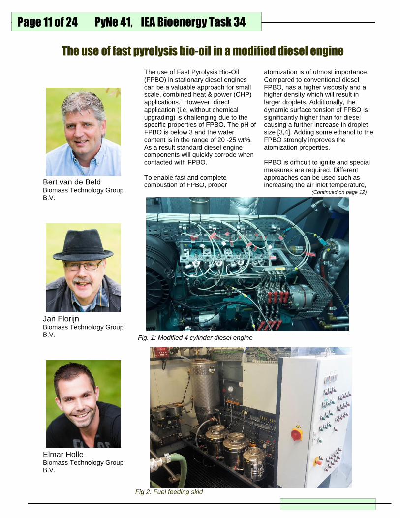
atomization is of utmost importance. Compared to conventional diesel FPBO, has a higher viscosity and a higher density which will result in larger droplets. Additionally, the dynamic surface tension of FPBO is significantly higher than for diesel causing a further increase in droplet size [3,4]. Adding some ethanol to the FPBO strongly improves the atomization properties. FPBO is difficult to ignite and special measures are required. Different approaches can be used such as increasing the air inlet temperature,
The use of Fast Pyrolysis Bio-Oil (FPBO) in stationary diesel engines can be a valuable approach for small scale, combined heat & power (CHP) applications. However, direct application (i.e. without chemical upgrading) is challenging due to the specific properties of FPBO. The pH of FPBO is below 3 and the water content is in the range of 20 -25 wt%. As a result standard diesel engine components will quickly corrode when contacted with FPBO. To enable fast and complete combustion of FPBO, proper
The use of fast pyrolysis bio-oil in a modified diesel engine
Fig. 1: Modified 4 cylinder diesel engine
Bert van de Beld Biomass Technology Group B.V.
Elmar Holle Biomass Technology Group B.V.
Jan Florijn Biomass Technology Group B.V.
Fig 2: Fuel feeding skid
(Continued on page 12)

PyNe 41, IEA Bioenergy Task 34 Page 12 of 24
increasing the compression ratio, adding cetane improvers to the fuel, or pilot fuel injection. Engine modification BTG has modified two compression-ignition engines to develop this application, viz. a one-cylinder and a four-cylinder prototype. Initial work was done with the 1-cylinder engine which has the advantage that only 1 fuel injection system needs to be constructed and installed. More recently, the modification of the four cylinder engine started which can be seen as a prototype for a commercial size CHP system. The prototype is based on the Weichai 226B engine, and the complete gen-set has been assembled and supplied by ABATO Motoren BV, the Netherlands. Subsequently, the unit has been modified by BTG to enable FPBO fueling. Four corrosion resistant fuel pumps and fuel injectors have been constructed in-house. The fuel pump is a two-stage system meaning that the original fuel pump is driving a 2nd fuel pump. The latter pump is connected to the fuel injector, and
smoothly and stable the fuel type is switched to rinsing liquid (ethanol or butanol) and engine will run for 5 or 10 minutes on this fuel. Finally, the switch is made to FPBO. So far all tests have been carried out with FPBO containing 20 wt% ethanol. The FPBO was produced by the Empyro plant from woody biomass. Initial results The major modification to the engine concerns the fuel feeding pumps and fuel injectors. To evaluate the new components their performance has been compared to the standard ones. Initially, reference runs have been carried out with diesel and the standard fuel pumps and injectors. Next, only the four fuel pumps were replaced with the modified fuel pumps, and the test runs were repeated with diesel as fuel. Finally, the new fuel injectors were installed and the same tests were carried out again. In Fig 3A and 3B the results of these tests are shown. Fig. 3A shows the fuel consumption for the three configurations as a function of the electrical load. Hardly any difference is
direct contact of FPBO with original parts of the engine is avoided. To overcome the poor ignition of FPBO the incoming air can be preheated; the compression ratio is kept to the original value of 18. Some pictures of the unit are shown in Fig. 1 and 2. The engine is started on diesel, and subsequently the inlet air heater is switched on. If the engine is running
Fig. 3A: Specific fuel consumption as a function of the load
The use of fast pyrolysis bio-oil in a modified diesel engine
Fig. 3A: Specific fuel consumption as a function of the load
(Continued on page 13)
PyNe 41, IEA Bioenergy Task 34
Page 13 of 24
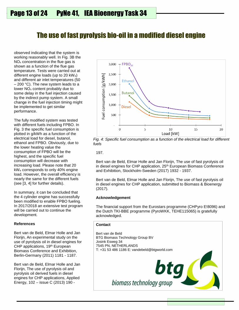
observed indicating that the system is working reasonably well. In Fig. 3B the NOx concentration in the flue gas is shown as a function of the flue gas temperature. Tests were carried out at different engine loads (up to 20 kWe) and different air inlet temperatures (50 – 200 °C). The new system leads to a lower NOx content probably due to some delay in the fuel injection caused by the indirect pump system. A small change in the fuel injection timing might be implemented to get similar performance. The fully modified system was tested with different fuels including FPBO. In Fig. 3 the specific fuel consumption is plotted in g/kWh as a function of the electrical load for diesel, butanol, ethanol and FPBO. Obviously, due to the lower heating value the consumption of FPBO will be the highest, and the specific fuel consumption will decrease with increasing load. Please note that 20 kWe corresponds to only 40% engine load. However, the overall efficiency is nearly the same for the different fuels (see [3, 4] for further details). In summary, it can be concluded that the 4 cylinder engine has successfully been modified to enable FPBO fueling. In 2017/2018 an extensive test program will be carried out to continue the development. References Bert van de Beld, Elmar Holle and Jan Florijn, An experimental study on the use of pyrolysis oil in diesel engines for CHP applications, 19th European Biomass Conference and Exhibition, Berlin-Germany (2011) 1181 - 1187. Bert van de Beld, Elmar Holle and Jan Florijn, The use of pyrolysis oil and pyrolysis oil derived fuels in diesel engines for CHP applications, Applied Energy, 102 – issue C (2013) 190 -
197. Bert van de Beld, Elmar Holle and Jan Florijn, The use of fast pyrolysis oil in diesel engines for CHP application, 25th European Biomass Conference and Exhibition, Stockholm-Sweden (2017) 1932 - 1937. Bert van de Beld, Elmar Holle and Jan Florijn, The use of fast pyrolysis oil in diesel engines for CHP application, submitted to Biomass & Bioenergy (2017). Acknowledgement The financial support from the Eurostars programme (CHPyro E!8096) and the Dutch TKI-BBE programme (PyroWKK, TEHE115065) is gratefully acknowledged. Contact Bert van de Beld BTG Biomass Technology Group BV Josink Esweg 34 7545 PN, NETHERLANDS T: +31 53 486 1186 E: [email protected]
Fig. 4: Specific fuel consumption as a function of the electrical load for different fuels
The use of fast pyrolysis bio-oil in a modified diesel engine

PyNe 41, IEA Bioenergy Task 34 Page 14 of 24
Calcined
petroleum
coke
Calcined
biocoke
(hardwood)
(wt%) C >96 98.5
H < 0.1 0.2
N 1 – 1.5 0.3
O 0 < 1.0
S 3 – 4 <0.05
(ppm) Ni < 200 < 10
V < 300 < 10
Na < 100 220
K -- 220
Ca < 200 166
Si < 250 240
Zn < 10 22
P < 10 9
Resistivity (mΩ*m)
< 100 100 – 200
% ash < 0.4 < 0.2
%volatiles < 0.4 < 0.2
Typically, the distillation of petroleum, followed by coking of the residues, produces ‘green petcoke’. The green coke is then sent to an industrial calciner for conversion into calcined petroleum coke (CPC). CPC is the only known material which can serve as anode material for the electrochemical reduction of Al2O3 into aluminium metal at industrially relevant scales. The main reason for this exclusivity revolves around the combination of properties, such as high electrical conductivity, high thermal tolerance, low ash and impurities (S, Ni, V, et. al.), high bulk density, and low coefficient of thermal expansion (CTE) [1]. Aluminum smelting uses consumable anodes which produce 1.5 tonne CO2/ tonne Al. Although some smelters can utilize hydroelectric power, at least a third of their total CO2 footprint originates from aluminum production. Furthermore, petroleum-based cokes are plagued by continually waning quality; high sulfur concentrations (5 – 6 wt%) often prevent smelters from meeting regulatory limits on emissions. Metallic impurities such as Ni, V, and alkali metals can either reduce current efficiency or otherwise contaminate
Biorenewable calcined coke as a pyrolysis co-product
Yaseen Elkasabi Sustainable Biofuels and Coproducts USDA-ARS
adequate quality of crystallite structure
is for the oil to contain elevated
aromaticity. Heteroatoms such as
DistillationResidues
Hydrocarbons
Phenolics
Acids
Calcination
~ 1200 oC
Calcined coke
Highly aromatic
bio-oils
Figure 1. Overview of how renewable calcined coke is made from bio-oils.
the aluminum product, leading up to $100/tonne coke in financial losses. One option to reduce the CO2 footprint is to source coke from biorenewable sources. At USDA-ARS, our goal has been to follow an analogous approach towards production of green and calcined cokes [1, 2], using catalytic and/or tail-gas reactive pyrolysis (TGRP) bio-oils (Figure 1). The bio-oils underwent batch distillation in typical laboratory glassware, making sure to maintain the residues in a molten state at elevated temperatures while collecting the distillates. The remaining residues typically have 30 – 45 wt% volatiles remaining. Subsequently, the residues undergo complete devolatilization (appx 900 oC) followed by calcination under inert atmosphere (1000 – 1200 oC).
While our initial product’s elemental
properties met and/or exceeded many
critical criteria measured for petroleum
(Table 1), physical properties had yet
to be tested. In particular, the degree
of polyaromatic crystallite stacking is
tied to many other important physical
properties such as real density and the
coefficient of thermal expansion. One
primary requirement for ensuring
Table 1. Typical properties for both petroleum and biomass-derived calcined cokes
(Continued on page 15)

PyNe 41, IEA Bioenergy Task 34
Page 15 of 24
oxygen prevent crystalline alignment
of PAHs via elevated viscosity and
cross-linking reactions. However, we
have demonstrated that this common
rule of thumb is not necessarily the
case for bio-oils with less than 15 – 17
wt% oxygen.
By modifying the distillation procedure,
we produced coke samples with high
degrees of anisotropy. Images from
polarized light microscopy (Figure 2)
illustrate the increase in anisotropy,
compared with what was produced
beforehand. Anisotropic textures are
the most favorable for smelting anodes
and comprise the majority of anodes.
Isotropic textures can be used as
blends with anisotropic cokes.
Amorphous cokes cannot be used at
all due to their tendency to crack under
thermal shock. When compared with
these standards, the coke we’ve
produced constitutes isotropic coke
with largely anisotropic domains, as
indicated by the stacking and
alternation of colored regions.
We are currently focusing on
developing larger-scale and/or
continuous processing of bio-oil
distillation residues. Recently, our lab
acquired a laboratory-scale tube
furnace that more closely mimics
rotary kilns used to calcine petroleum
coke industrially. More industrially
relevant process parameters should
now be obtained since there would be
a more accurate emulation of heat and
mass transport phenomena. The tube
furnace can also attain a maximum
temperature of 1600 oC, significantly
beyond that limits of our muffle
furnaces. Our goal is to produce
larger-scale batches of biorenewable
calcined coke for use in pilot-scale
anode testing and for characterization
of mechanical properties.
References
[1] Y. Elkasabi, A.A. Boateng, M.A. Jackson, “Upgrading of bio-oil
distillation bottoms into biorenewable calcined coke” Biomass and
Bioenergy (2015), 81, 415 – 423.
[2] Y. Elkasabi, H. Darmstadt, A.A. Boateng, “Coke produced from lower-
oxygen fast-pyrolysis oil: a new approach to produce renewable anode
raw materials” in Light Metals 2017, The Minerals, Metals, & Materials
Society (2017), A.P. Ratvik (ed.), 1221 – 1227.
Contact
Yaseen Elkasabi, Ph.D.
Research Chemical Engineer
Sustainable Biofuels and Coproducts
USDA-ARS, Eastern Regional Research Center
600 E. Mermaid Lane, Wyndmoor PA 19038
(215) 836-3797
Biorenewable calcined coke as a pyrolysis co-product…continued
250 mm
(a)
100 mm
(d)
250 mm
(b)
250 mm (c)
Figure 2. Polarized light microscopy images of pyrolysis oil-based calcined coke (a) initial amorphous samples. Subsequent improvements produced (b and c) mixed isotropic and anisotropic samples. (d) higher resolution image of mostly isotropic region.

PyNe 41, IEA Bioenergy Task 34 Page 16 of 24
Solvent liquefaction (SL) of biomass
is a promising technology for the
conversion of biomass to renewable
fuels and chemicals. Liquid-phase
thermal deconstruction of biomass in
the presence of hydrocarbon-based
hydrogen-donating solvents can
result in bio-oils with low moisture
and low oxygen content. These oils
are thermally stable and highly
miscible with hydrocarbon streams,
which make them a promising
biorenewable blendstock for
petroleum refineries.
At Iowa State University, we have
developed a 1 kg hr-1 continuous SL
pilot plant (Figure 1) to evaluate the
performance of SL of southern
yellow pine in a hydrocarbon solvent
[1]. The process development unit
(PDU) was also designed to
evaluate several unit operations
critical to large-scale operations.
PDU Operation
Three separate experiments, each
more than twelve hours long, were
conducted with the unit using
Southern yellow pine sawmill
Continuous solvent liquefaction research at Iowa State University
vessel operated at 400 °C and 43
bar. The solvent vapor pressure at
this temperature was estimated to
be 12.3 bar.
Liquids and solids exited the bottom
of the reactor and entered a solids
filtration vessel. A 50 µm stainless
steel pleated mesh filter separated
the particulate matter from the heavy
liquid as it was pumped out of the
vessel with a high-viscosity pump,
passing through a 5 µm stainless
steel filter to a vessel where the
liquid, a mixture of heavy product
bio-oil and solvent, was stored for
subsequent bio-oil fractionation.
Vapors and non-condensable gas
products exited the top of the reactor
and entered the first of three stages
of liquid recovery. The first stage
condensed vapors to liquids at 260
°C with the goal of recovering
hydrocarbons and/or phenolic
monomers produced during solvent
liquefaction. Any remaining
condensable vapors were collected
in the second stage of liquid
recovery, which was mostly water
Robert C. Brown Iowa State University
residue dried to 4% moisture and
ground and sieved to 6.4 mm (0.25
in) size.
The solvent was a blend of two
hydrocarbon liquids. The majority of
the solvent was comprised of
commercially available naphthalene-
depleted heavy aromatic solvent
(CAS # 64742-94-5). The hydrogen
donor solvent was a proprietary cut
of light cycle oil (LCO) (CAS #
64741-59-9) that was specially
hydrotreated.
Biomass feeding was done in a two-
stage process. The first feeder
consisted of a 15 L hopper on top of
a single-screw auger that metered
biomass at a constant rate of 0.7
kg/h. The second stage was an
extruder with two co-rotating,
intermeshed screws where solvent
was injected into the feed stream
with a solvent-to-biomass ratio of
approximately 4:1. Pressures in the
extruder ranged from 42 to 53 bar.
The biomass/solvent slurry was
injected directly from the extruder
exit into the side of the reaction
(Continued on page 17)
Fig. 1 - A 1 kg/h continuous pilot plant was constructed to evaluate the performance of solvent liquefaction of southern yellow pine in a hydrocarbon solvent

PyNe 41, IEA Bioenergy Task 34
Page 17 of 24
and light oxygenated compounds.
Gases exiting this second stage
passed through a 10 µm barrier filter
and into the third stage of recovery,
which was a knockout vessel
designed to remove any fume from
the non-condensable gas stream
before gas analysis.
To improve separation of heavy bio-
oil and solid residue recovered from
the bottom of the reactor, an optional
system for injecting acetone into this
mixture and subsequently recovering
the acetone was constructed. The
liquid stream entered this step at
approximately 120 °C, while the
vessel itself was controlled to 93 °C
and 1.1 bar. The operating
conditions were established such
that acetone would flash from the
liquid phase and carry overhead into
the next separation unit. No other
compounds were expected to flash
off with acetone due to the low
volatility of the compounds present
in this portion of the system.
After solids and acetone were
removed from the liquid stream, bio-
oil was transferred to the bio-oil
fractionation system. The primary
goal of this system was to separate
a cut of the bio-oil for use as a
potential recycle solvent. This cut
was targeted to contain molecules
near the boiling point range of the
hydrocarbon solvent. Hot nitrogen
gas was used as the stripping agent.
The overheads stream passed
through a heat exchanger that
condensed products at 5 °C and
were collected in another separator.
Liquefaction Performance
Three tests were conducted to
evaluate the overall liquefaction
performance and repeatability of the
SL PDU. At least three steady-state
samples were collected for each run
to determine averages. Most of the
bio-oil from fast pyrolysis, which is often
in the range of 10-20 MJ/kg. The
average oxygen balance across the
three runs was determined (Figure 2).
Approximately 17.6 wt% of the initial
oxygen in the feedstock was recovered
as water produced from dehydration and
hydrodeoxygenation.
Decarbonylation and decarboxylation
were prominent means for
deoxygenation. Over 23.4 wt% oxygen
was rejected from the biomass through
these reactions. This resulted in
approximately 55.6 and 3.4 wt% of the
oxygen remaining in the bio-oil and solid
residue, respectively. Considering the
initial oxygen content of the southern
yellow pine was 41.7 wt% this results in
a total oxygen content of 23.2 wt% in
the bio-oil as a whole.
Char was removed with the acetone-
free on-line filtration system for at least
6 h of continuous operation without
clogging the filters. The total calculated
filtration efficiency was 99.8%.
Acetone separation from the heavy bio-
oil achieved 97% efficiency (i.e. 3%
acetone loss) at a flash temperature of
135 °C. Additional increases in the
vessel temperature were expected to
product gas was accounted for in the
overhead products system; however,
some degassing did occur in the
solids filtration and acetone recovery
system due to the pressure letdown
in solids removal system.
Primary gases produced during
liquefaction were CO2 and CO,
products of biomass decarboxylation
and decarbonylation, respectively.
Minor gaseous products were light
hydrocarbons (CH4, C2H4, and
C2H6).The bio-oil yield for the
system ranged from 47.2 wt% to
54.1 wt%, with an average of 51.2
wt% across the three runs. On
average, the mass fraction of
remaining products was essentially
equal: aqueous (13.4 wt%), gas
(17.7 wt%), and char (18.8 wt%)
products.
Due to the tendency of the bio-oils to
separate into organic and aqueous
phases, bio-oils had very low
moisture content. This behavior is
attributed to partial hydro-
deoxygenation of the bio-oil by the
hydrogen donor included in the
solvent mixture. The higher heating
value (HHV) was also higher than for
Fig. 2 - Oxygen balance across the whole system on an ash-free, moisture-free biomass basis. Error bars represent the standard error of the mean for the three runs.
Continuous solvent liquefaction research at ISU…continued
0%
10%
20%
30%
40%
50%
60%
70%
Bio-oil Water Gas SolidO
xyge
n D
istr
ibu
tio
n (
wt%
)
Product
(Continued on page 18)
PyNe 41, IEA Bioenergy Task 34 Page 18 of 24
result in improved separation
efficiency, but long-term thermal
stability of the bio-oil was a concern
at elevated temperatures.
Prior to implementation of the
fractionation system, a series of
tests were conducted to determine
the thermal stability of the product
stream. Only modest changes of
about 5% or less were found for the
bio-oil, and increasing temperature
up to 300 °C appeared to have
insignificant influence compared to
lower temperatures. The conclusion
was that the heavy oil product
exhibited sufficient thermal stability
to remain unchanged following
thermal fractionation up to 300 °C.
After the operating conditions of the
bio-oil fractionation system were
established, several extended-
duration experiments were
conducted to verify its operational
consistency. For more than 25 h of
run time the average split was 24%
bottoms and 76% overheads, each
with a 1% standard error of the
mean. The overheads were
predominantly recovered
hydrocarbon solvent and wood-
derived monomers with boiling
points below 204 °C. This stream
accounts for approximately 93 wt%
of the initial solvent input. The
overheads product was a low-
viscosity clear liquid with an amber
hue. It is suitable for use as recycle
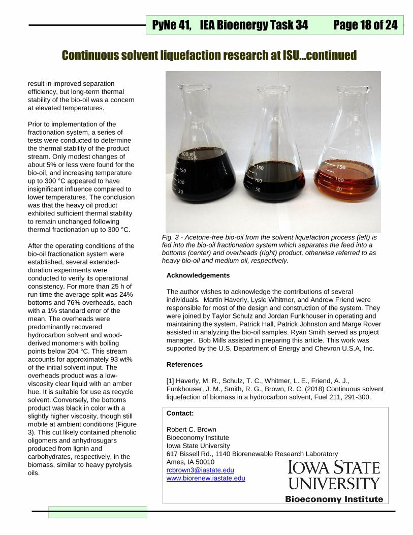
solvent. Conversely, the bottoms
product was black in color with a
slightly higher viscosity, though still
mobile at ambient conditions (Figure
3). This cut likely contained phenolic
oligomers and anhydrosugars
produced from lignin and
carbohydrates, respectively, in the
biomass, similar to heavy pyrolysis
oils.
Acknowledgements
The author wishes to acknowledge the contributions of several
individuals. Martin Haverly, Lysle Whitmer, and Andrew Friend were
responsible for most of the design and construction of the system. They
were joined by Taylor Schulz and Jordan Funkhouser in operating and
maintaining the system. Patrick Hall, Patrick Johnston and Marge Rover
assisted in analyzing the bio-oil samples. Ryan Smith served as project
manager. Bob Mills assisted in preparing this article. This work was
supported by the U.S. Department of Energy and Chevron U.S.A, Inc.
References
[1] Haverly, M. R., Schulz, T. C., Whitmer, L. E., Friend, A. J.,
Funkhouser, J. M., Smith, R. G., Brown, R. C. (2018) Continuous solvent
liquefaction of biomass in a hydrocarbon solvent, Fuel 211, 291-300.
Contact:
Robert C. Brown
Bioeconomy Institute
Iowa State University
617 Bissell Rd., 1140 Biorenewable Research Laboratory
Ames, IA 50010
www.biorenew.iastate.edu
Fig. 3 - Acetone-free bio-oil from the solvent liquefaction process (left) is fed into the bio-oil fractionation system which separates the feed into a bottoms (center) and overheads (right) product, otherwise referred to as heavy bio-oil and medium oil, respectively.
Continuous solvent liquefaction research at ISU…continued

PyNe 41, IEA Bioenergy Task 34
Page 19 of 24
Licella has developed the Catalytic
Hydrothermal Reactor (Cat-HTR™)
platform as a hydrothermal upgrading
process to transform a wide variety of
low cost biomass feedstocks, wastes
and residues into a stable biocrude.
Licella’s biocrude can be refined, using
conventional refinery infrastructure, to
a range of fuels and chemicals,
including:
Drop-in fuels, low Sulfur
(Gasoline, Kerosene, Diesel,
Gas and Fuel Oils) when co-
processed with conventional
petroleum feedstocks
Chemicals, that can be used,
for example, as components in
products such as adhesives
and tacifiers
The Cat-HTR™ has processed a wide
variety of feedstocks that can be
processed wet, removing the need for
any pre-drying step.
The Cat-HTR™ is a highly controllable
process, enabling it to process a wide
process is able to utilise inexpensive
and non-proprietary catalysts.
About Licella™
Licella™ was founded in 2007 and is a
subsidiary of Ignite Energy Resources
(IER). Licella ™ was formed to focus
on commercialising the Cat-HTR™
platform for biomass. In 2007 the first
design of the Cat-HTR™ (Generation
1) was completed and this very first
plant was commissioned in early 2008,
at Somersby on the New South Wales
Central Coast, about an hour north of
range of feedstocks, typically taking
between 15-25 minutes to produce the
biocrude that is stable, miscible and
for forest residues, normally has a
calorific value of 34-36 Mj/kg
(feedstock dependant).
The Cat-HTR™ process utilises
equipment that is already in
widespread use in other industries,
meaning capital costs are kept to a
minimum. Operationally most of the
energy required to initiate the series of
transformational cascading chemical
reactions is recovered. In addition the
Licella and the Catalytic Hydrothermal Reactor (Cat-HTR™)
of the Cat-HTR™ technology, resulting
in the construction of the current Large
Pilot Plant. The final scale up to a
commercial scale module is a x 2.2
scale up of the existing Large Pilot
Plant reactors.
Sydney, Australia.
Since then, Licella™ has used the
pilot plant facility, to refine the Cat-
HTR™ process for optimal yield,
product quality and economics. This
has involved three separate scale-ups
Steve Rogers Licella
Fig. 1: Examples of feedstock that have been processed by the Cat-HTR™ platform experimental runs.

PyNe 41, IEA Bioenergy Task 34 Page 20 of 24
`
Cat-HTR™ Development
The Cat-HTR™ platform was invented
in Australia by Dr Len Humphreys,
Licella™ CEO, and Professor Thomas
Maschmeyer, of the University of
Sydney.
“We began developing the Cat-
HTR™ technology in 2005, from a
related approach involving the use of
supercritical methanol to convert
simpler and much more economical
upgrading process.”
“The same Cat-HTR™
transformational principles that work
for lignite can, with some
modifications, also be applied to
biomass, such as pulp and paper
residues. We are today incredibly
excited to be moving towards our
fourth generation and commercial
scale Cat-HTR™ plants with our
partners.”
Technology Development to
Commercialisation
Licella™ has formed a global joint
venture with Canfor Pulp, a Canadian
(TSX) listed leading global supplier of
pulp and paper products. The joint
venture was formed to integrate
Licella’s Cat-HTR™ platform into kraft
and mechanical pulp mills, utilising
waste streams to create renewable
fuels and chemicals. Canfor and
Licella have formed a joint project
team who are currently undertaking
engineering work to integrate the Cat-
HTR into Canfor Pulp’s Prince George
(British Columbia) mill.
edible oils to biodiesel. We needed a
feedstock which was non-edible,
abundant and low cost. Lignite
became the new feedstock, and water
the processing medium in late 2006.”
“For many decades people had tried to
upgrade lignite by drying it. The
breakthrough for us happened when
we turned this approach on its head –
embracing water as the agent of
change, not the enemy. This lead to a
Fig 2: Cat-HTR™ scale-up showing reactor progression
Dr Len Humphreys, CEO & Co-Founder
Prof Dr Thomas Maschmeyer FAA FTSE, Technology Consultant & Co-Founder
Licella and the Catalytic Hydrothermal Reactor (Cat-HTR™)
IMAGE 3: Cat-HTR inventors Dr Len Humphreys and Professor Dr Thomas Maschmeyer

PyNe 41, IEA Bioenergy Task 34
Page 21 of 24
Once integrated, the Cat-HTR™
platform will convert wood residues
from the kraft pulping processes, into
renewable biocrude, to produce
advanced biofuels and biochemicals.
This additional residue stream refining
would allow Canfor Pulp to further
optimise their pulp production
capacity.
The formation of the joint venture
follows a successful program of trials
conducted on feedstock from Canfor
Pulp’s Prince George pulp mill at
Licella’s pilot plants in Australia.
Upon successful integration of the Cat-
HTR™ technology, the joint venture
look towards offering the Cat-HTR™
solution to Kraft and mechanical pulp
mills globally.
Contact:
Steve Rodgers [email protected]
For more information on Licella visit:
www.licella.com
To view our corporate video, visit:
www.licella.com/our-story
IMAGE 4: Licella’s Generation 3 Cat-HTR™ reactors, at the Large Pilot Plant in Somersby, NSW
IMAGE 5: Canfor’s 3 pulp mills in Prince George British Columbia and the
Husky Energy refinery
Licella and the Catalytic Hydrothermal Reactor (Cat-HTR™)

PyNe 41, IEA Bioenergy Task 34 Page 22 of 24
PYRENA is a novel integrated system
that features ONE reactor in which fast
pyrolysis and combustion are
combined. PYRENA is suitable for
(catalytic) fast pyrolysis and offers
continuous catalyst recycling in one
heat-integrated system. Especially the
flexibility regarding the use of catalysts
is an attractive option, because it
offers a route (via in-situ and ex-situ
catalysis) to a better bio-oil that
probably requires less downstream
test on fast pyrolysis [1]. PYRENA
bio-oil from poplar and wheat straw
was nicely comparable with other
state-of-the art pyrolysis reactors. The
pyrolysis of hybrid poplar fines (<0.5
mm), prepared by Idaho National
Laboratories, yielded 64% of a one-
phase oil (based on the poplar intake
weight a.r.) containing 42% organics
and 22% water. Overall mass balance
was 98% (64% oil, 12% gas, 22%
char). For the wheat straw fines (also
prepared by Idaho National
Laboratories, US) the results were
remarkably different. A clear two-
phase oil was obtained in a yield of
44% (based on the straw intake a.r.).
Almost half of the liquid was water
(24%) and 20% organic substances.
Mass balance was incomplete at 82%
(44% oil, 9% gas, 29% char).
The PYRENA set-up has been
modelled in a coarse techno-economic
evaluation, aimed at a scale of 300
kt/yr of dry biomass intake. Assuming
300 kton/a (dry) biomass (softwood),
Paul J. de Wild Energy research Centre of the Netherland (ECN)
upgrading when compared to
analogous pyrolysis systems.
PYRENA consists of a bubbling
fluidised bed reactor vessel, in the
center of which an internal riser
reactor is located for the pyrolysis, see
Figure 1. Biomass is fed to the riser
reactor at a maximum feed rate of 5
kg/hr and pyrolysed at 400 – 600°C.
The required heat is provided by hot
sand or catalyst that circulates from
the surrounding bubbling bed into the
riser. The sand is heated via the
combustion of the pyrolysis char that is
transported from the riser reactor via
an internal cyclone. The hot pyrolysis
vapours are quickly quenched and
recovered via direct or fractionated
condensation. The PYRENA system is
roughly comparable to a circulating
fluidised bed (CFB) system. A major
difference is the integration; most
state-of-the-art CFB reactors use an
external reactor for combustion of the
char and heating of the sand.
Figure 2 presents a detailed flow
scheme of the reactor set-up, including
product collection.
PYRENA has successfully participated
in a recent international round robin
(Continued on page 23)
PYRENA: PYROLYSIS EQUIPMENT FOR NEW APPROACHES
Figure 2: Detailed flow scheme of the PYRENA reactor set-up, including product collection
Figure 1: PYRENA consists of a bubbling fluidised bed reactor vessel, in the center of which an internal riser reactor is located for the pyrolysis

PyNe 41, IEA Bioenergy Task 34
Page 23 of 24
8000 hrs operation, CFB pyrolysis,
thermal pyrolysis(TP) followed by
catalytic hydrodeoxygenation (HDO)
was compared with catalytic pyrolysis
(CP) using state-of-the-art ZSM5
catalysts. TPHDO was modelled
using experimental data, while for CP
literature data were used [2, 3]. An
Excel model was constructed to
calculate mass- and energy balances
from both exp and literature data.
Results indicate a higher oil yield (36%)
and less char (13%) for the TPHDO
approach than for CP (17% oil, 24%
char), while CAPEX was higher for
TPHDO when compared to CP (100
M€ vs 70 M€).
Summary
In future work, PYRENA will be used to
study the effect of the environmentally
benign mineral olivine as a mild, cheap
and easily regenerable cracking
catalyst on the fast pyrolysis of
softwood. Presently, focus is on
fractionated recovery of pyrolysis
products from lignin and lignin-rich
biomass types to produce ample
samples in sufficient quantity for further
processing and/or application trials.
2. F. de Miguel Mercader, Pyrolysis oil
upgrading for co-processing in standard
refinery units, PhD thesis Twente
University, 2010.
3. V. Paasikallio, C. Lindfors, E.
Kuoppala, Y. Solantausta, A. Oasmaa,
J. Lehto, J. Lehtonen, Product quality
and catalyst deactivation in a four day
catalytic fast pyrolysis production run,
Green Chem. 2014, 16, 3549
Contact: Dr. Paul J. de Wild
Energy research Centre of the
Netherland (ECN),
Westerduinweg 3, 1755 LE Petten,
The Netherlands
PYRENA was deployed in a recent
Dutch national Catalytic Pyrolysis
project to produce bio-oil samples for
the project consortium and to tests
catalysts. The project dealt with the
application of catalysis in dedicated
pyrolysis reactors aiming at improving
the quality of the produced oil. One of
the target applications of the oil is a
refinery co-feed. PYRENA is a
promising candidate.
Acknowledgements
This research has been performed
within the framework of the CatchBio
program. The authors gratefully
acknowledge the support of the Smart
Mix Program of the Netherlands
Ministry of Economic Affairs and the
Netherlands Ministry of Education,
Culture and Science.
References
1. D.C. Elliott, D. Meier, A. Oasmaa, B.
van de Beld, A.V. Bridgwater, M.
Marklund, K. Toven, “Results of the IEA
Round Robin on fast pyrolysis bio-oil
production”, Energy Fuels, 2017, 31
(5), pp 5111–5119.
PYRENA: PYROLYSIS EQUIPMENT FOR NEW APPROACHES…continued
Figure 3: PYRENA process flow diagram for techno-economic evaluation including pyrolysis and hydrodeoxygenation

Disclaimer: This Task 34 newsletter was edited and produced by the Task Leader on behalf of IEA Bioenergy Task 34 Direct Thermochemical Liquefaction. Any opinions or material contained within are those of the contributors and do not necessarily reflect any views or policies of the International Energy Agency or any other organization.
For More Information
IEA Bioenergy Task 34 Website task34.ieabioenergy.com/ IEA Bioenergy www.ieabioenergy.com/ Past Issues of the Task 34 Newsletters task34.ieabioenergy.com/iea-publications/ Pyrolysis Demoplant Database task34.ieabioenergy.com/publications/pyrolysis-demoplant-database/ If you would like to contribute an article to the Task 34 newsletter, or have questions, please contact: Pyne Editor: [email protected]
Or visit us at task34.ieabioenergy.com/
December 2017
Task 34: Direct Thermochemical Liquefaction IEA Bioenergy