IDTTM IN-DIE TAPPING - daytonlamina.com · The special forming taps used in the in-die taping units...
12
IDT TM IN-DIE TAPPING
-
Upload
nguyenthuan -
Category
Documents
-
view
219 -
download
0
Transcript of IDTTM IN-DIE TAPPING - daytonlamina.com · The special forming taps used in the in-die taping units...

IDTTM
IN-DIE TAPPING

In-Die Tapping
In-Die Tapping Provides the Following Advantages and Benefi ts: Off-the-shelf ordering
Eliminates secondary or off-line tapping operations; form and tap in the same operation
Cam-operated ME tapping units designed to optimize performance in most mechanical presses
Compact, low profi le LP tapping units with no limitations on tapping angle; tap upwards, downwards or at any angle in between
Provides misfeed protection against a no-hole condition
Cold formed tapping results in high-strength threads without chip formation
Easy to move from one die set to another
No limitation with open die height or press stroke
HY1024 Series 1 ME1024 Series 2
LP25M6 & LP516M8 Series 3
Accessories and Replacement Parts LP Extensions 4Forming Taps 5Pitch Inserts and Tapholders 6
Maximum Tapping Depth/Material Thickness 7
Lubrication – Tapping Fluid 8
Tapping Unit Lubrication Kits 8
Made in the U.S.A.
PAGE NUMBER
1
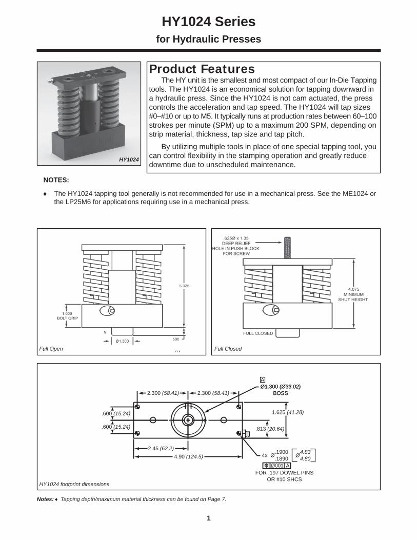
The HY unit is the smallest and most compact of our In-Die Tapping tools. The HY1024 is an economical solution for tapping downward in a hydraulic press. Since the HY1024 is not cam actuated, the press controls the acceleration and tap speed. The HY1024 will tap sizes #0–#10 or up to M5. It typically runs at production rates between 60–100 strokes per minute (SPM) up to a maximum 200 SPM, depending on strip material, thickness, tap size and tap pitch. By utilizing multiple tools in place of one special tapping tool, you can control fl exibility in the stamping operation and greatly reduce downtime due to unscheduled maintenance.
A
.813 (20.64)
.1900 4.83
.1890 4.80
Ø1.300 (Ø33.02)BOSS
Ø1.300 (Ø33.02)BOSS2.300 (58.41)2.300 (58.41)
.600 (15.24)
.600 (15.24)
1.625 (41.28)
4.90 (124.5)2.45 (62.2)
FOR .197 DOWEL PINSOR #10 SHCS
4x Ø Ø
Ø001 A
HY1024 Seriesfor Hydraulic Presses
Product Features
HY1024
HY1024 footprint dimensions
Notes: Tapping depth/maximum material thickness can be found on Page 7.
NOTES:
The HY1024 tapping tool generally is not recommended for use in a mechanical press. See the ME1024 or the LP25M6 for applications requiring use in a mechanical press.
Full Open Full Closed

2
The ME1024 is a simple and compact In-Die Tapping tool for tapping downward in a mechanical or hydraulic press. The ME1024 utilizes a cam driver to control tool acceleration. The ME will tap sizes #0–#10 or up to M5 and typically runs at production rates between 60–100 strokes per minute (SPM) up to a maximum 200 SPM depending on strip material, thickness, tap size and tap pitch. The cam driver is designed as a separate functional piece to maximize die design fl exibility and transfer the inherent sinusoidal motion of the press into a rotary motion for tapping. The cam driver mounts easily on a punch plate or upper die shoe above the tapping tool. The cam driver is application specifi c and can be manufactured by using the free “Rapid TAP” CAD design software. By utilizing multiple tools in place of one special tapping tool, you can control fl exibility in the stamping operation and greatly reduce downtime due to unscheduled maintenance.
Product Features
ME1024 Seriesfor Mechanical and Hydraulic Presses
ME1024
Notes: Tapping depth/maximum material thickness can be found on Page 7. All dimensions are in inches.
A = TAPPING STROKE + 5.776
ME1024 footprint dimensions
Full Open Full Closed

3
The LP is the most versatile of our mechanical In-Die Tapping tools with a simple and compact design capable of tapping in any direction. The LP units utilize a cam driver to control tool acceleration and tap speeds. The LP25M6 will tap size #0 – 1/4 or M6 and the LP516M8 will tap 1/4" – 5/16" or M8 while making either right or left-hand threads. The LP typically runs at production rates between 20–60 strokes per minute (SPM) up to a maximum of 100 SPM depending on strip ma-terial, thickness, tap size and tap pitch. The cam driver is designed as a separate functional piece to maximize die design fl exibility and transfer the inherent sinusoidal motion of the press into a rotary motion for tapping. The cam driver mounts easily on a punch plate on the upper die shoe above the tapping unit to provide the proper amount of tap acceleration and a positive return. The cam driver is application-specifi c and can be manufactured by using the free “Rapid TAP” CAD design software. Multiple standard tools can be used in place of a special multi-head tapping tool to add fl exibility and greatly reduce downtime.
LP25M6 & LP516M8 Seriesfor Mechanical and Hydraulic Presses
LP25M6
Product Features
Notes: Footprint dimensions are identical for both units. However, performance variations exist between the two units. Consult the Rapid Tap software. Tapping depth/maximum material thickness can be found on Page 7. All dimensions are in inches.
LP25M6 & LP516M8 footprint dimensions
NOTE A: Dowel pin holes ±0.001 Fastener holes ±0.005
The shut height from the upper shoe to the mounting surface cannot be less than 3.775", without engineered modifi cations.DO NOT manually alter the cam contour generated by the RapidTap software.
Important Note
4
Accessories and Replacement Parts
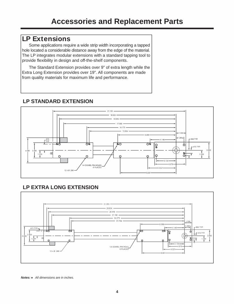
LP STANDARD EXTENSION
LP EXTRA LONG EXTENSION
Some applications require a wide strip width incorporating a tapped hole located a considerable distance away from the edge of the material. The LP integrates modular extensions with a standard tapping tool to provide fl exibility in design and off-the-shelf components. The Standard Extension provides over 9" of extra length while the Extra Long Extension provides over 19". All components are made from quality materials for maximum life and performance.
LP Extensions
Notes: All dimensions are in inches.

5
Accessories and Replacement Parts
The special forming taps used in the in-die taping units are available in inch and metric standard sizes listed below. All forming taps are sold with a TiN coating as standard. Other coatings for special material applications are available on request. Forming taps provide a superior quality and fi nish of thread, with no chip formation.
Forming Taps —Product Features
Standard Stock Taps are TiN CoatedSpecial Tap Sizes, Pitches and Coatings are Available per Quotation
1 Tap diameter shank size application: Small – 0 – #10 (M2 – M5) diameter taps: use in HY1024, ME1024, LP25M6 Medium – #12, ¼" and M6 diameter taps: use in LP25M6 Large – ¼" – 5/16" (M6 - M8) diameter taps: use in LP516M8
Taps are sold in packs of 12.
INCH SIZES
Part Number Shank Size1Tap Size &
D Limit R-006004 Small 2 - 56 – RH3R-006008 Small 4 - 40 – RH5R-006033 Small 4 - 40 – RH7R-006010 Small 5 - 40 – RH5R-006013 Small 6 - 40 – RH5R-006009 Small 4 - 48 – RH5R-006012 Small 6 - 32 – RH5R-006031 Small 6 - 32 – RH7R-006014 Small 8 - 32 – RH5R-006030 Small 8 - 32 – RH7R-006017 Small 10 - 32 – RH6R-006032 Small 10 - 32 – RH8R-006016 Small 10 - 24 – RH6R-006023 Medium 12 - 28 – RH6R-006022 Medium 12 - 24 – RH6R-006021 Medium 1/4 - 28 – RH6R-006090 Large 1/4 - 28 – RH6R-006020 Medium 1/4 - 20 – RH6R-006091 Large 1/4 - 20 – RH6R-006092 Large 5/16 - 32 – RH6R-006093 Large 5/16 - 24 – RH6R-006094 Large 5/16 -18 – RH7
METRIC SIZES
Part Number Shank Size1Tap Size &
D LimitR-006042 Small M2.0 x .40 D5R-006044 Small M2.5 x .45 D5 R-006045 Small M3.0 x .50 D5R-006046 Small M3.5 x .60 D6R-006047 Small M4.0 x .70 D6R-006049 Small M5.0 x .80 D7 R-006050 Medium M6.0 x 1.00 D8R-006095 Large M6.0 x 1.00 D8R-006096 Large M8.0 x 1.00 D8R-006097 Large M8.0 x 1.25 D8

6
Pitch inserts are interchangeable components of the tapping operation and are specifi c to the pitch of the tapped hole. Each pitch insert contains a tap holder with a quick release ball-detent collar. Taps can be easily changed in most applications. For applications which tap inside an embossment, a pitch insert extension can be made specifi c to your needs. Our engineering department will work with you to customize a pitch insert for your application.
Pitch Inserts/Tap Holders —Product Features
Accessories and Replacement Parts
Pitch inserts for non-standard sizes or pitches are by quotation.
1 Tap diameter shank size application: Small – 0 – #10 (M2 – M5) diameter taps: use in HY1024, ME1024, LP25M6 Medium – #12, ¼" and M6 diameter taps: use in LP25M6 Large – ¼" – 5/16" (M6 - M8) diameter taps: use in LP516M8
INCH SIZES
PitchTap
HolderSize1
PartNumber
for HY/ME1024
PartNumber
forLP25M6
Part Number
forLP516M8
56 Small R-002005 R-002024 —48 Small R-002006 R-002025 —40 Small R-002007 R-002026 —32 Small R-002008 R-002027 —28 Small R-002013 — —28 Medium — R-002031 —28 Large — — R-002112
10-24 Small R-002010 R-002029 —12-24 Medium R-002014 R-002032 —
5/16-24 Large — — R-00211320 Medium — R-002030 —20 Large — — R-00211418 Large — — R-002115
METRIC SIZES
PitchTap
HolderSize1
PartNumber
forHY/ME1024
PartNumber
forLP25M6
Part Number
forLP516M8
0.40 mm Small R-002048 R-002068 —0.45 mm Small R-002047 R-002067 —0.50 mm Small R-002046 R-002066 —0.60 mm Small R-002045 R-002065 —0.70 mm Small R-002044 R-002064 —0.80 mm Small R-002042 R-002062 —1.00 mm Medium — R-002060 —1.00 mm Large — — R-0021161.25 mm Large — — R-002117

7
Maximum Tapping Depth/Material Thickness
NOTE: Maximum material thickness (T) includes extrusion height and .020 inch (or 0.5mm) gap between the tip of the tap and the top of the material stock.
MAXIMUM MATERIAL THICKNESS (T) - INCH
Size andPitch
HY & ME1024
LP25M6 LP516M8
2-64 0.080 — —2-56 0.091 0.180 —3-56 0.091 0.180 —3-48 0.106 0.220 —4-48 0.106 0.220 —4-40 0.128 0.240 —5-44 0.116 0.270 —5-40 0.128 0.270 —6-40 0.128 0.270 —6-32 0.159 0.260 —8-36 0.142 0.250 —8-32 0.159 0.250 —
10-32 0.159 0.250 —10-24 0.213 0.230 —12-28 0.182 0.230 —12-24 0.213 0.220 —1/4-28 — 0.220 0.3001/4-20 — 0.190 0.290
5/16x32UN — — 0.2605/16x24UN — — 0.3405/16x18UN — — 0.275
MAXIMUM MATERIAL THICKNESS (T) - METRIC
Size andPitch
HY & ME1024
LP25M6 LP516M8
M2 x .4 2.0 3.9 —M2.5 x .45 2.2 4.5 —
M3 x .5 2.5 5.1 —M3 x .6 3.0 6.3 —
M3.5 x .6 3.0 6.3 —M4 x .7 3.5 6.6 —M5 x .8 4.0 6.3 —M5 x .9 4.5 5.9 —M6 x 1.0 — 5.6 8.6M8 x 1.0 — — 8.6M8 x 1.25 — — 7.9

8
Lubrication – Tapping Fluid
R-EDP00002 Pint Bottle R-EDP00003 Case of 12 Pint Bottles R-EDP00006 Case of 4 Gallon Bottles (case only) R-EDP00004 5-Gallon Pail
Designed specifi cally for forming taps
Faster tapping speeds
Extends tap life
Product Features
Forming Tap Lubrication
Tapping Unit Lubrication Kits
ME, HY Lubrication Kit R-003001 Tube of red grease Pint of red oil Grease gun 18" fl ex extension for grease gun Small diameter hydraulic coupler 90° fi tting for grease gun Straight extension for hydraulic coupler Oil can
** LP Lubrication Kit Model R-003002 Required with the ME, HY Lubrication kit
for use with LP tools Rubber tip 1/8" coupling
R-003002
R-003001

In-Die Tapping Application Sheet
CUSTOMER INFORMATION
Date: ________________________________
Company Name: ____________________________________________________________Contact Name: _____________________________________________________________ Contact Phone: _____________________________________________________________ Contact Email: ______________________________________________________________Address: __________________________________________________________________ _________________________________________________________________________ State: _______________________________ ZIP: _________________________________
PRESS INFORMATION
Press Type: Mechanical ____Hydraulic _____Press Stroke: __________________________Tapping Stroke: ________________________Stripper Travel: ________________________Desired Speed: ________________________
PART INFORMATION
Material Type: _________________________Diameter & Pitch: _______________________Number of Taps: _______________________Hole Layout: __________________________Tapping Direction (check one): Top Down ___Bottom Up ___Sideways ___Total Depth to Tap (T): __________________Clearance Gap (g): _____________________
Part Print Sent? Yes __________ No ___________Strip Layout Sent? Yes _________ No ___________
Part and layout prints are very helpful to ensure proper unit selection. Please send TO THE ATTENTION OF: In-Die Tapping Application Engineering Department, at
FAX: 800-406-4410 or EMAIL: [email protected]
9

© 2013 IEM. All rights reserved. 341 (W) 07/13
Committed to Quality & Customer Satisfaction
Anchor Lamina America, Inc. is a leading manufacturer of tool, die and mold components for the metal-working and plastics industries. As a customer focused, world-class supplier of choice, we provide the brands, product breath, distribution network and technical support for all your metal forming needs.
We will help our customers to compete globally by providing innovative and value added products and services.
Distributed by:
a MISUMI Group Company
Anchor Lamina America, Inc.38505 Country Club Drive Suite 100
Farmington Hills, MI USA 48331Tel: 001-248-489-9122 Fax: 001-248-553-6842
E-Mail: [email protected]
www.anchorlamina.com


![[PPT]No Slide Title - Wikispacesptec107.wikispaces.com/file/view/Flow_Measurement.ppt · Web viewFlange Taps Corner Taps Radius Taps Vena-Contracta Taps Pipe Taps Multivariable Pressure](https://static.fdocuments.in/doc/165x107/5ad6f9207f8b9a32618bb97e/pptno-slide-title-viewflange-taps-corner-taps-radius-taps-vena-contracta-taps.jpg)

![FARM TAPS 2019.pptx [Read-Only]Farm Taps • Exercise of Enforcement Discretion Regarding Farm Taps – Issued March 28, 2019 • Choice of managing risk to farm taps by either §192.740](https://static.fdocuments.in/doc/165x107/600e7275e0429a22ec32de4b/farm-taps-2019pptx-read-only-farm-taps-a-exercise-of-enforcement-discretion.jpg)