Identified Company (CompositeX) to manufacture Custom Composite Pressure Vessel ● Working pressure...
60
Identified Company (CompositeX) to manufacture Custom Composite Pressure Vessel ● Working pressure 1000psi ● Holds 8 kg Nitrous Oxide ● 700 cubic inch volume ● HDPE lined ● 1.4 lbs Composite Pressure Vessel (Chalice Concept) Liquid Nitrous Oxide Nitrous Oxide Vapor 8” 14”
-
date post
21-Dec-2015 -
Category
Documents
-
view
220 -
download
0
Transcript of Identified Company (CompositeX) to manufacture Custom Composite Pressure Vessel ● Working pressure...
Identified Company (CompositeX) to manufacture Custom Composite Pressure Vessel
●Working pressure 1000psi●Holds 8 kg Nitrous Oxide●700 cubic inch volume ●HDPE lined●1.4 lbs
Composite Pressure Vessel(Chalice Concept)
Liquid NitrousOxide
NitrousOxide Vapor
8”
14”
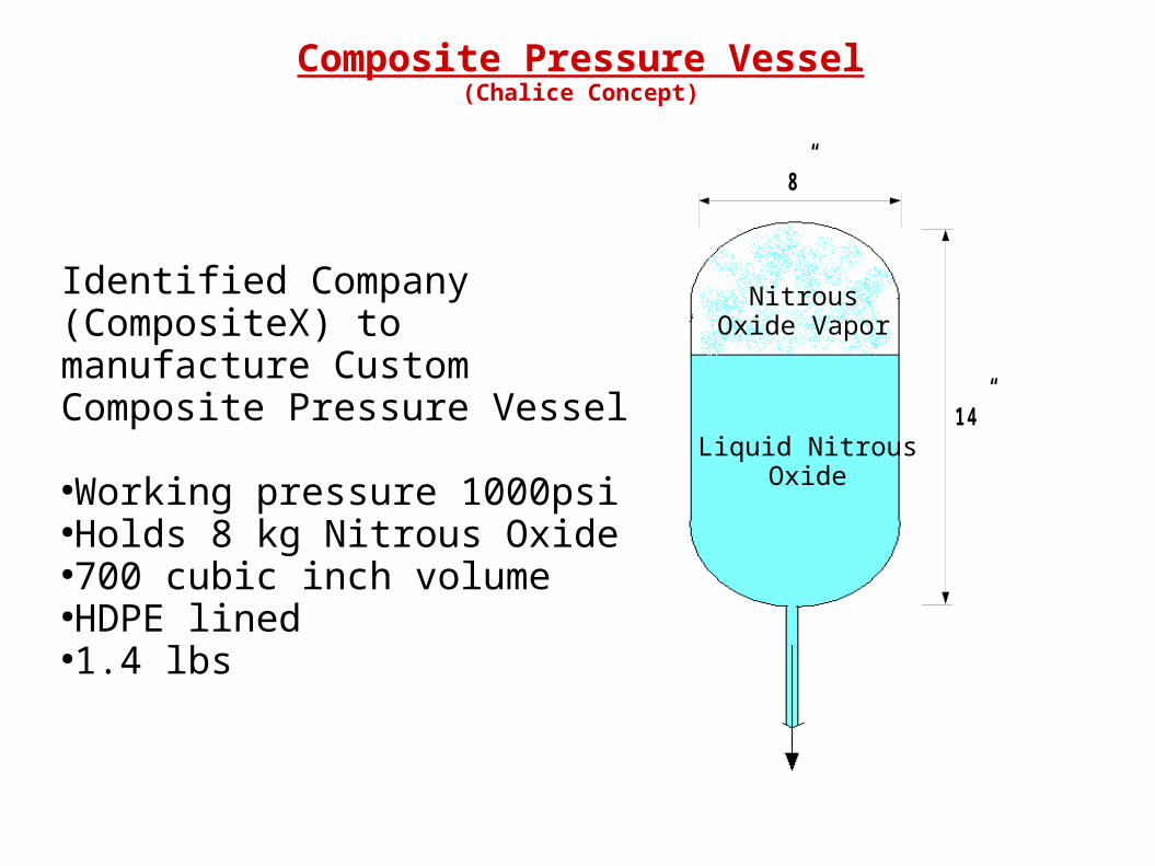
Composite Pressure Vessel(Chalice Concept)
Helium Gas
Liquid NitrousOxide
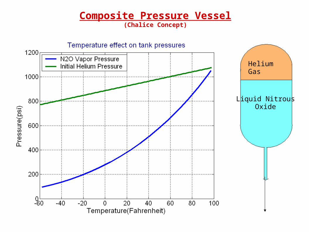
Composite Pressure Vessel(Chalice Concept)
●Ideal gas law used to model helium pressure
➔ p=m*R*T/V
●Verified from pressure/ temperature data that Helium will remain gaseous
➔ Compressibility factor ~1, so ideal gas assumption valid
●Tank weights listed estimated from quote of 700ci=1.4 lbs
➔ Also includes weight of Helium (case dependent)
Aluminum/Titanium Comparison
Aluminum alloy Aluminum alloy Titanium Alloy
Property 7075-T6 (ww-T-700) drawn tubing 7075-T6; 7075-T651 Grade 5 Ti6Al4V % Different
Source Casing.xls Matweb Matweb
Yield Strength (Mpa) 455 503 1103 219.28%
Ultimate Strength (Mpa) 531 572 1172 204.90%
E (Gpa) 71.76 71.76 113.85 158.65%
0.33 0.33 0.33
Density (g/cc) 2.81 4.43 157.65%
Melting Temp (oC) 477 1600 335.43%
Thermal Conductivity (W/m-K) 130 6.7 5.15%
Specific Heat (J/g-K) 0.96 0.5263 54.82%
Mass Calculation
Short Grain
HTPB Mass(kg) N2O Vol (m^3) N2O Vol (m^3) Structure Mass Allowable (10:2)
Multiplier 6 8 6 8
1.5 0.01144 0.01526 2.1 2.7
1.55 0.01182 0.01576 2.17 2.79
1.6 0.01220 0.01627 2.24 2.88
1.65 0.01259 0.01678 2.31 2.97
1.7 0.01297 0.01729 2.38 3.06
1.75 0.01335 0.01780 2.45 3.15
Long Grain
HTPB Mass(kg) N2O Vol (m^3) N2O Vol (m^3) Structure Mass Allowable (10:2)
Multiplier 3 6 3 6
2.5 0.00953 0.01907 2 3.5
2.55 0.00973 0.01945 2.04 3.57
2.6 0.00992 0.01983 2.08 3.64
2.65 0.01011 0.02021 2.12 3.71
2.7 0.01030 0.02059 2.16 3.78
2.75 0.01049 0.02098 2.2 3.85
Mass CalculationChalice Design, 7075-T6 Al
240mm OD, 1.75mm Thickness, FS 1.25
Short Grain
Low Height (cm) Low Mass (g) % All. Mass High Height (cm) High Mass (g) % All. Mass
26.05 973 46.32% 33.72 1259 46.65%
26.91 1005 46.32% 34.85 1301 46.65%
27.78 1038 46.32% 35.97 1343 46.65%
28.65 1070 46.32% 37.09 1385 46.65%
29.52 1102 46.32% 38.22 1427 46.65%
30.39 1135 46.32% 39.34 1469 46.65%
Long Grain
Low Height (cm) Low Mass (g) % All. Mass High Height (cm) High Mass (g) % All. Mass
21.70 811 40.53% 42.15 1574 44.98%
22.14 827 40.53% 43.00 1606 44.98%
22.57 843 40.53% 43.84 1637 44.98%
23.01 859 40.53% 44.68 1669 44.98%
23.44 875 40.53% 45.52 1700 44.98%
23.88 892 40.53% 46.37 1732 44.98%
Mass CalculationEmbedded Outer Shell Design, 7075-T6 Al
180mm OD, 61mm ID, 1.3mm Thickness, FS 1.25
Short Grain
Low Height (cm) Low Mass (g) % All. Mass High Height (cm) High Mass (g) % All. Mass
51.67 1075 51.19% 65.18 1356 50.23%
53.21 1107 51.02% 67.17 1398 50.10%
54.76 1139 50.86% 69.17 1439 49.97%
56.30 1171 50.71% 71.17 1481 49.86%
57.84 1203 50.57% 73.17 1522 49.75%
59.39 1236 50.43% 75.17 1564 49.65%
Long Grain
Low Height (cm) Low Mass (g) % All. Mass High Height (cm) High Mass (g) % All. Mass
43.75 910 45.51% 82.17 1710 48.85%
44.62 928 45.51% 83.67 1741 48.77%
45.50 947 45.51% 85.17 1772 48.68%
46.37 965 45.51% 86.67 1803 48.61%
47.25 983 45.51% 88.17 1834 48.53%
48.12 1001 45.51% 89.67 1866 48.46%
Mass CalculationEmbedded Inner Shell Design, Grade 5 Titanium
61mm OD, 0.5mm Thickness
Short Grain
Low Height (cm) Low Mass (g) % All. Mass High Height (cm) High Mass (g) % All. Mass
45.50 192 9.12% 45.50 192 7.09%
45.50 192 8.83% 45.50 192 6.87%
45.50 192 8.55% 45.50 192 6.65%
45.50 192 8.29% 45.50 192 6.45%
45.50 192 8.05% 45.50 192 6.26%
45.50 192 7.82% 45.50 192 6.08%
Long Grain
Low Height (cm) Low Mass (g) % All. Mass High Height (cm) High Mass (g) % All. Mass
63.00 265 13.26% 63.00 265 7.58%
63.00 265 13.00% 63.00 265 7.43%
63.00 265 12.75% 63.00 265 7.29%
63.00 265 12.51% 63.00 265 7.15%
63.00 265 12.28% 63.00 265 7.02%
63.00 265 12.06% 63.00 265 6.89%
Inner Shell (fuel grain housing)
Inner and Outer Shell ANSYS Stress Modeling (Embedded Fuel Grain Concept)
Outer radius: 2.40” (~61mm)
Inner radius: 2.36” (~60mm)
Height: 21.46” (~545 m)
Mat’l: Aluminum 7075 T6
Outer radius: 1.75” + 0.5 mm (0.03225 m)
Inner radius: 1.25” (0.03175 m)
Height: 1.5” (0.0381 m)
Mat’l: Al 7075 T6 with Composite over-wrap
Composite: IM7 Carbon (fiber) / PEEK (matrix)
Model Geometry
Outer Shell (NOS/rocket housing)
Material Properties
Al 7075-T6
(Modeled as Isotropic)
Density: 2810 kg/m3
Longitudinal Mod., E1: 71.7e9 Pa
Poisson’s Ratio, v12: 0.33
PEEK (matrix)
Density: 1376 kg/m3
IM7 Carbon Fiber (12,000 filaments)
(Modeled as Orthotropic)
Density: 1780 kg/m3
Longitudinal Mod., E1: 278e9 Pa
Poisson’s Ratio, v12: 0.20
Carbon/PEEK Composite
(Modeled as Isotropic)
Density: 1600 kg/m3
Longitudinal Mod., E1: 71.7e9 Pa
Transverse Mod., E2: 10.2e9 Pa
Poisson’s Ratio, v12: 0.30
Shear Modulus, G12: 5.7e9
Inner and Outer Shell ANSYS Stress Modeling (Embedded Fuel Grain Concept)
Outer Shell (w/ composite)
Inner and Outer Shell ANSYS Stress Modeling (Embedded Fuel Grain Concept)
Figure 1: Outer Shell of Imbedded Fuel Grain Design(Meshed Elements – 8node93)
Inner and Outer Shell ANSYS Stress Modeling (Embedded Fuel Grain Concept)
Outer Shell (w/ composite)
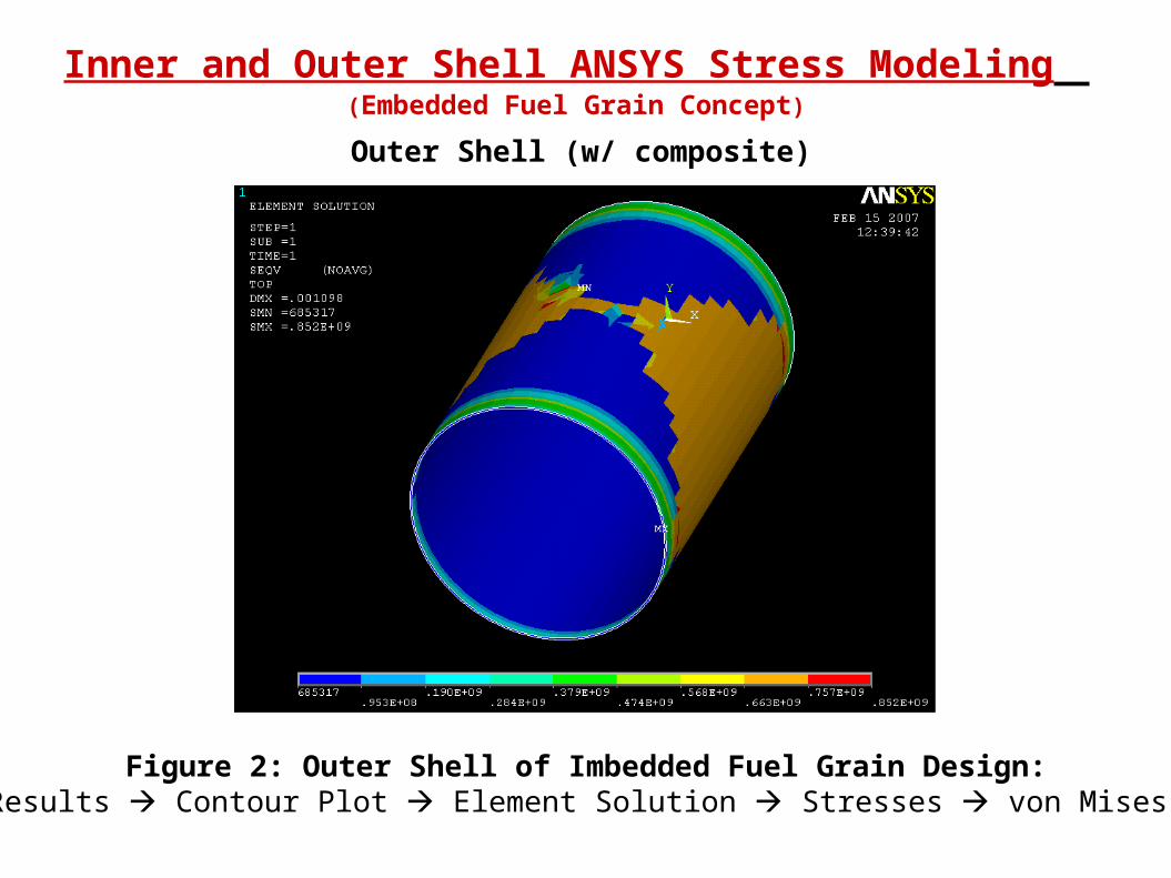
Figure 2: Outer Shell of Imbedded Fuel Grain Design: Plot Results Contour Plot Element Solution Stresses von Mises stress
Outer Shell (w/ composite)
Inner and Outer Shell ANSYS Stress Modeling (Embedded Fuel Grain Concept)
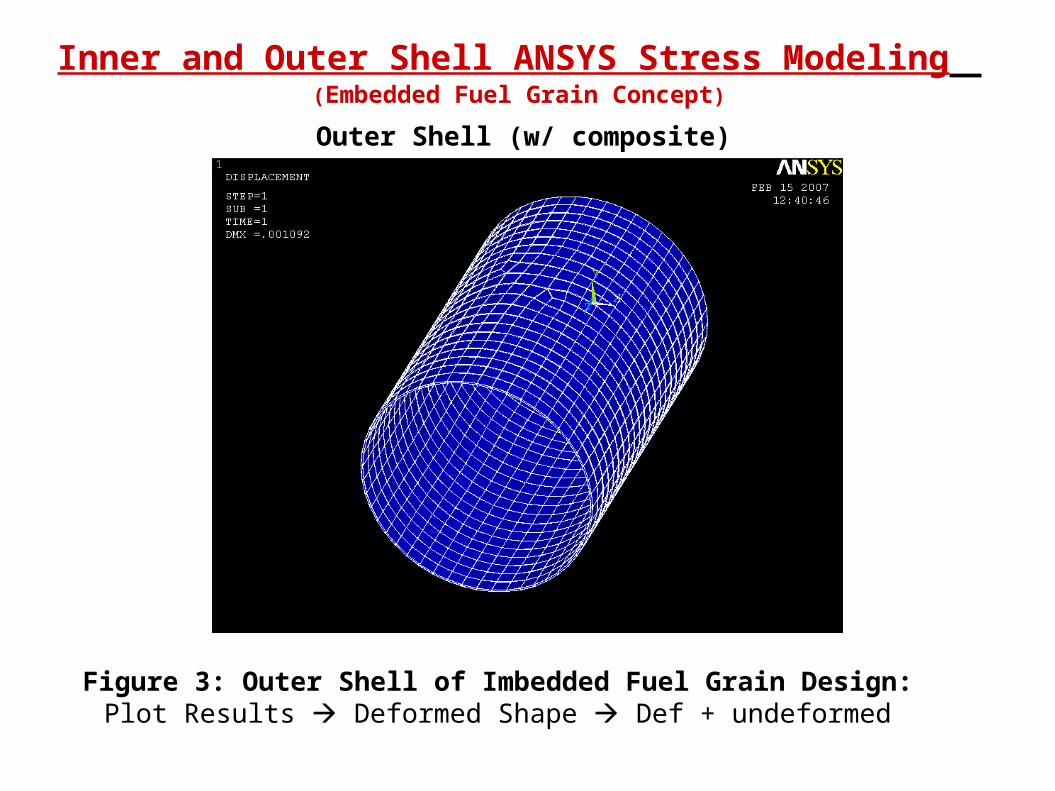
Figure 3: Outer Shell of Imbedded Fuel Grain Design: Plot Results Deformed Shape Def + undeformed
Outer Shell (w/ composite)
Inner and Outer Shell ANSYS Stress Modeling (Embedded Fuel Grain Concept)
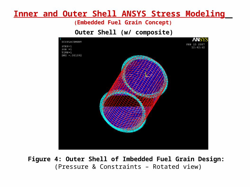
Figure 4: Outer Shell of Imbedded Fuel Grain Design: (Pressure & Constraints – Rotated view)
Outer Shell (w/ composite)
Inner and Outer Shell ANSYS Stress Modeling (Embedded Fuel Grain Concept)
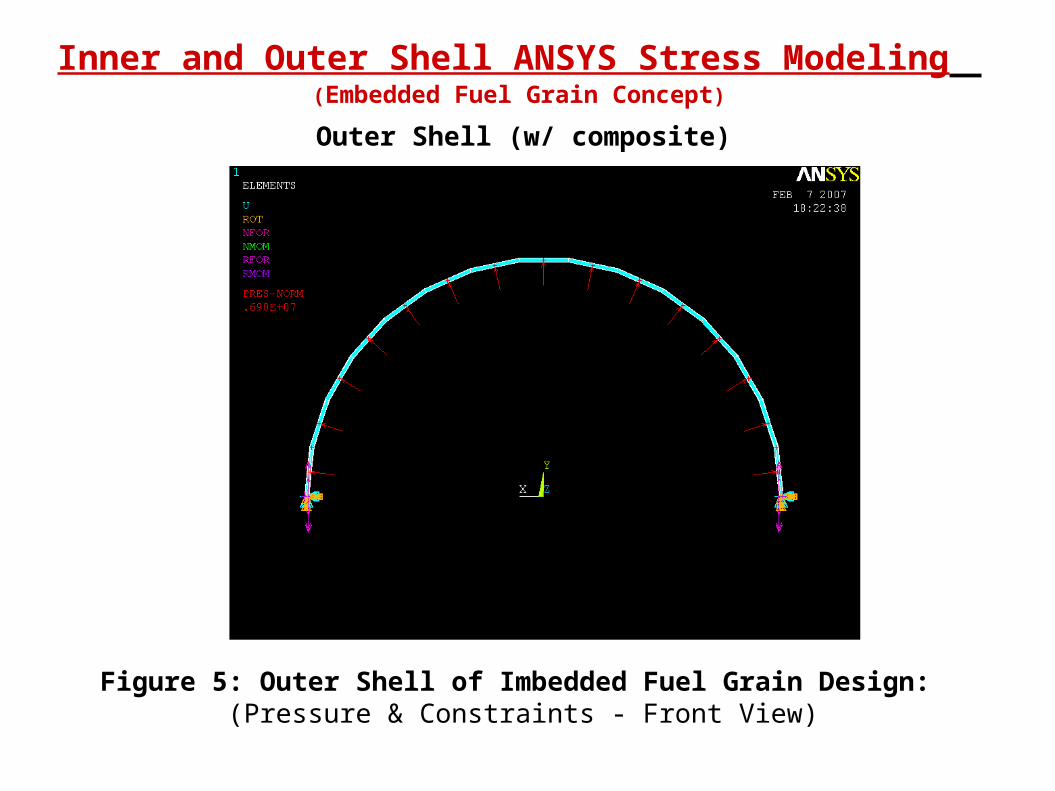
Figure 5: Outer Shell of Imbedded Fuel Grain Design: (Pressure & Constraints - Front View)
Outer Shell (w/ composite)
Inner and Outer Shell ANSYS Stress Modeling (Embedded Fuel Grain Concept)
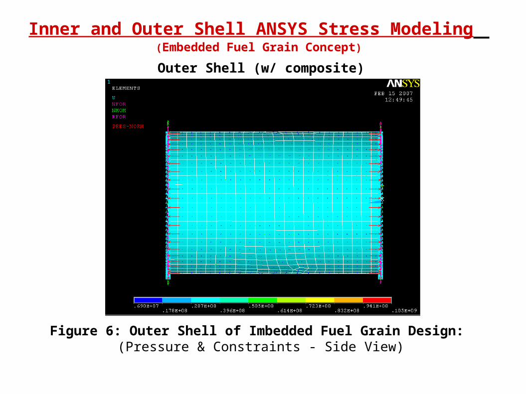
Figure 6: Outer Shell of Imbedded Fuel Grain Design: (Pressure & Constraints - Side View)
Inner Shell (All Aluminum)
Inner and Outer Shell ANSYS Stress Modeling (Embedded Fuel Grain Concept)
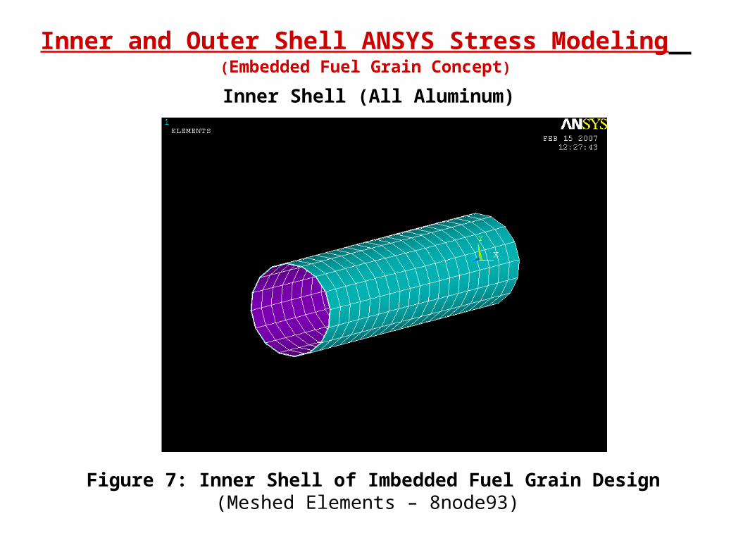
Figure 7: Inner Shell of Imbedded Fuel Grain Design(Meshed Elements – 8node93)
Inner Shell (All Aluminum)
Inner and Outer Shell ANSYS Stress Modeling (Embedded Fuel Grain Concept)
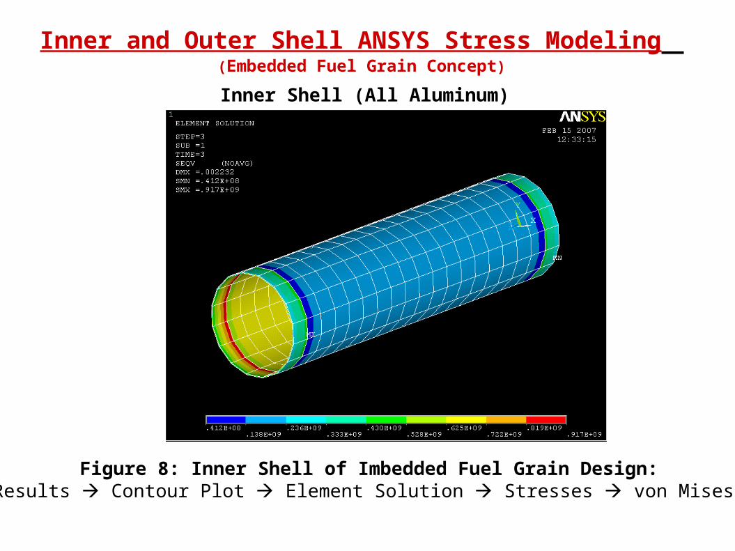
Figure 8: Inner Shell of Imbedded Fuel Grain Design: Plot Results Contour Plot Element Solution Stresses von Mises stress
Inner Shell (All Aluminum)
Inner and Outer Shell ANSYS Stress Modeling (Embedded Fuel Grain Concept)
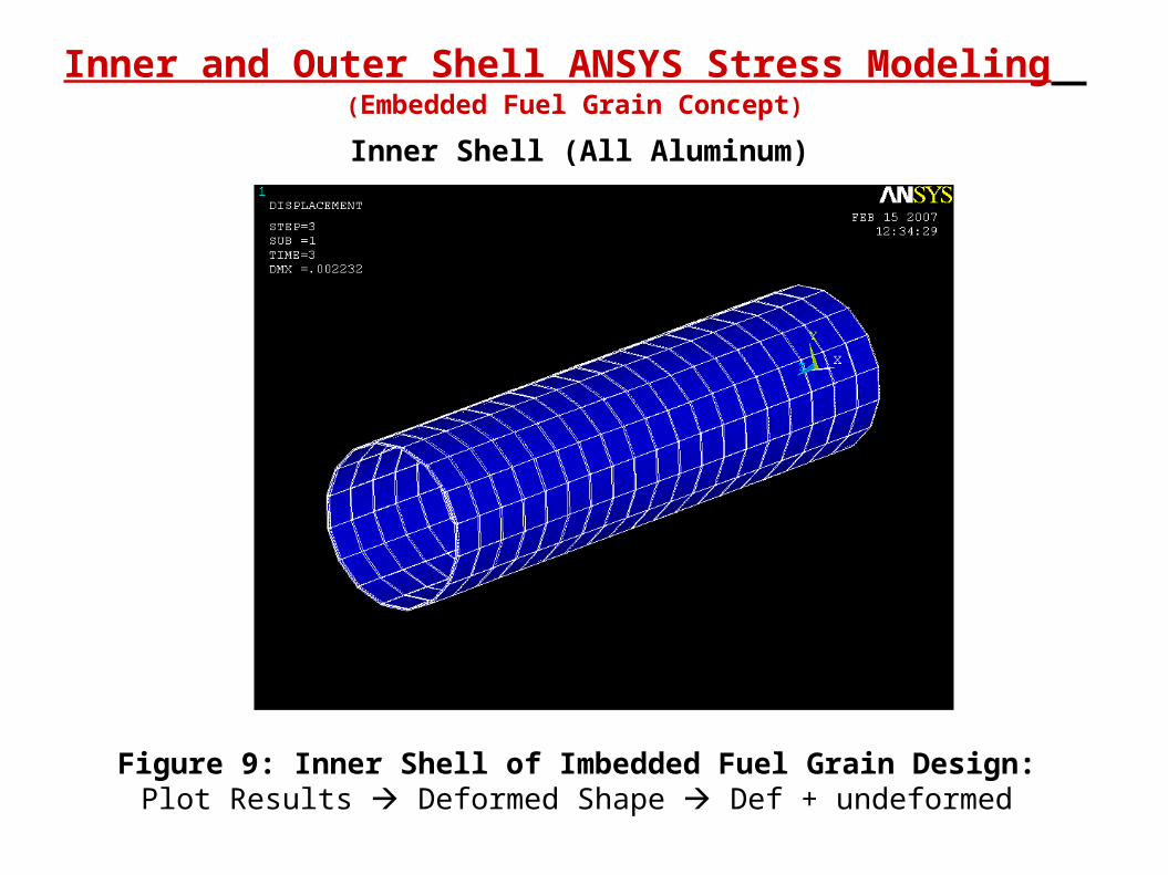
Figure 9: Inner Shell of Imbedded Fuel Grain Design: Plot Results Deformed Shape Def + undeformed
Inner Shell (All Aluminum)
Inner and Outer Shell ANSYS Stress Modeling (Embedded Fuel Grain Concept)
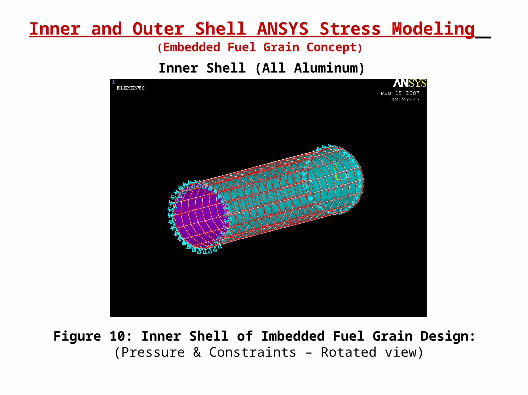
Figure 10: Inner Shell of Imbedded Fuel Grain Design: (Pressure & Constraints – Rotated view)
Inner Shell (All Aluminum)
Inner and Outer Shell ANSYS Stress Modeling (Embedded Fuel Grain Concept)
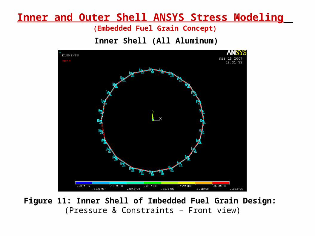
Figure 11: Inner Shell of Imbedded Fuel Grain Design: (Pressure & Constraints – Front view)
Inner Shell (All Aluminum)
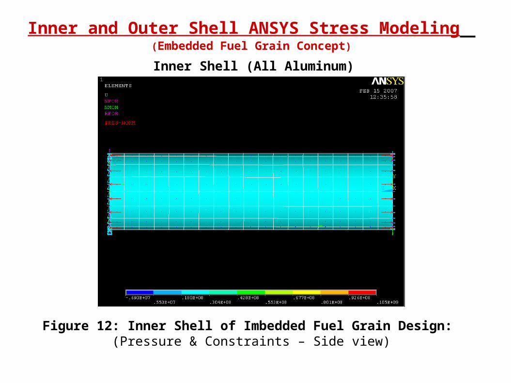
Inner and Outer Shell ANSYS Stress Modeling (Embedded Fuel Grain Concept)
Figure 12: Inner Shell of Imbedded Fuel Grain Design: (Pressure & Constraints – Side view)
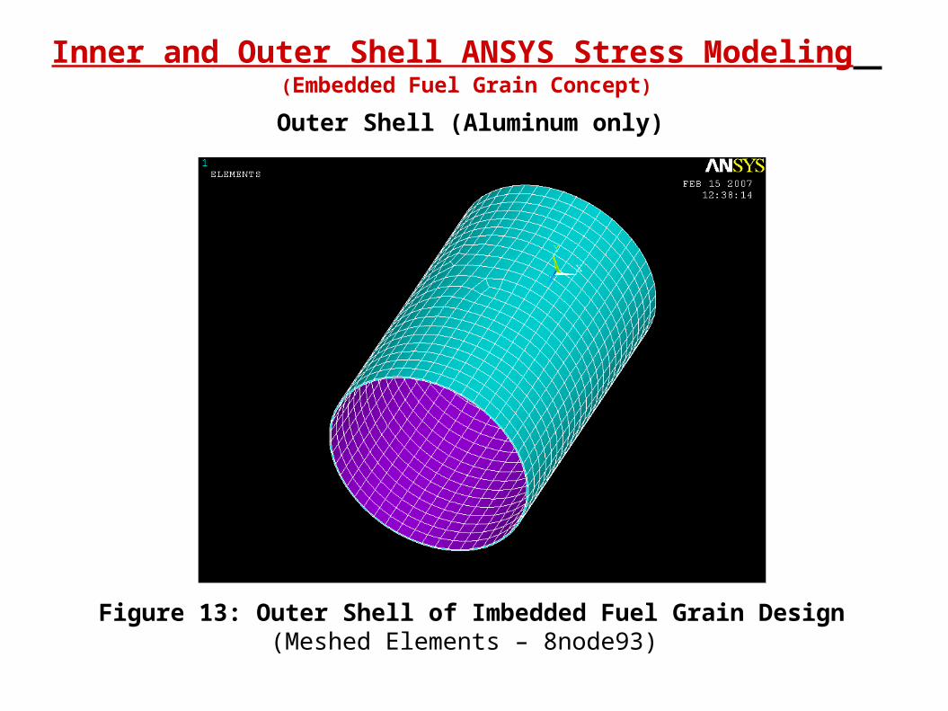
Outer Shell (Aluminum only)
Inner and Outer Shell ANSYS Stress Modeling (Embedded Fuel Grain Concept)
Figure 13: Outer Shell of Imbedded Fuel Grain Design(Meshed Elements – 8node93)
Outer Shell (Aluminum only)
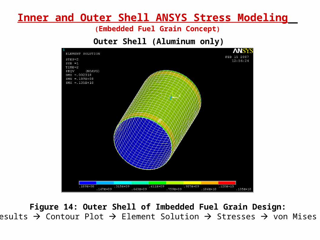
Inner and Outer Shell ANSYS Stress Modeling (Embedded Fuel Grain Concept)
Figure 14: Outer Shell of Imbedded Fuel Grain Design: Plot Results Contour Plot Element Solution Stresses von Mises stress
Outer Shell (Aluminum only)
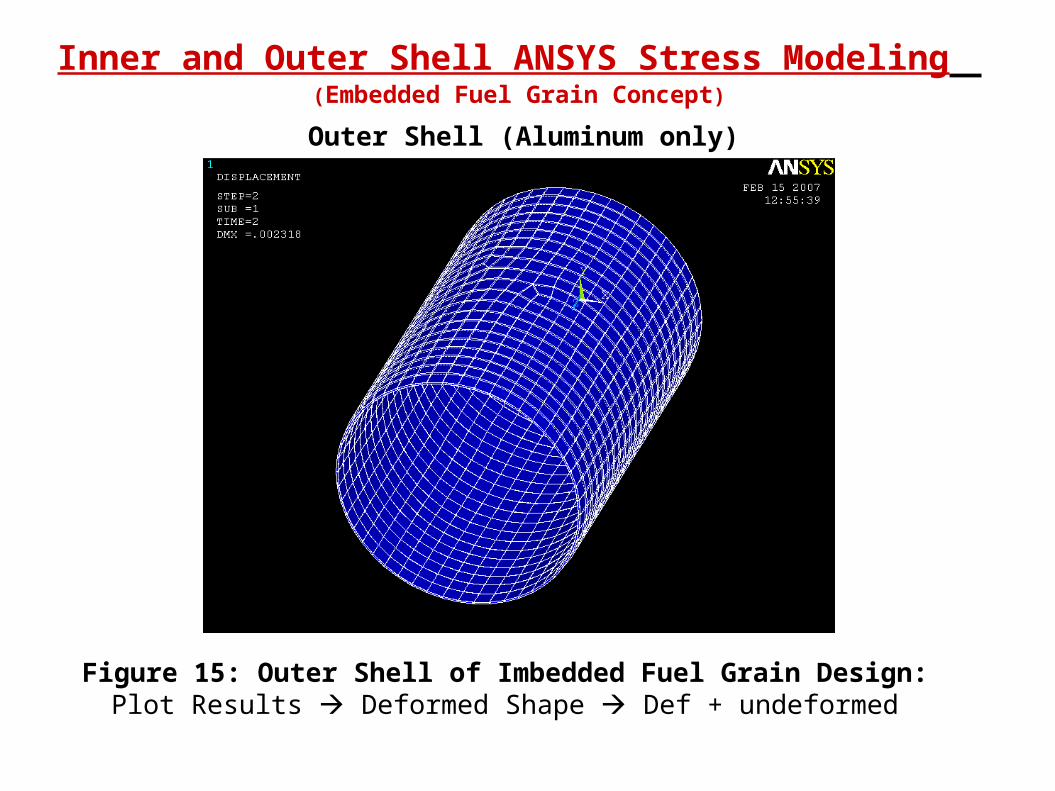
Inner and Outer Shell ANSYS Stress Modeling (Embedded Fuel Grain Concept)
Figure 15: Outer Shell of Imbedded Fuel Grain Design: Plot Results Deformed Shape Def + undeformed
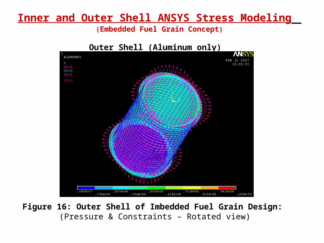
Inner and Outer Shell ANSYS Stress Modeling (Embedded Fuel Grain Concept)
Outer Shell (Aluminum only)
Figure 16: Outer Shell of Imbedded Fuel Grain Design: (Pressure & Constraints – Rotated view)

Inner and Outer Shell ANSYS Stress Modeling (Embedded Fuel Grain Concept)
Outer Shell (Aluminum only)
Figure 17: Outer Shell of Imbedded Fuel Grain Design: (Pressure & Constraints - Front View)

Inner and Outer Shell ANSYS Stress Modeling (Embedded Fuel Grain Concept)
Outer Shell (Aluminum only)
Figure 18: Outer Shell of Imbedded Fuel Grain Design: (Pressure & Constraints - Side View)
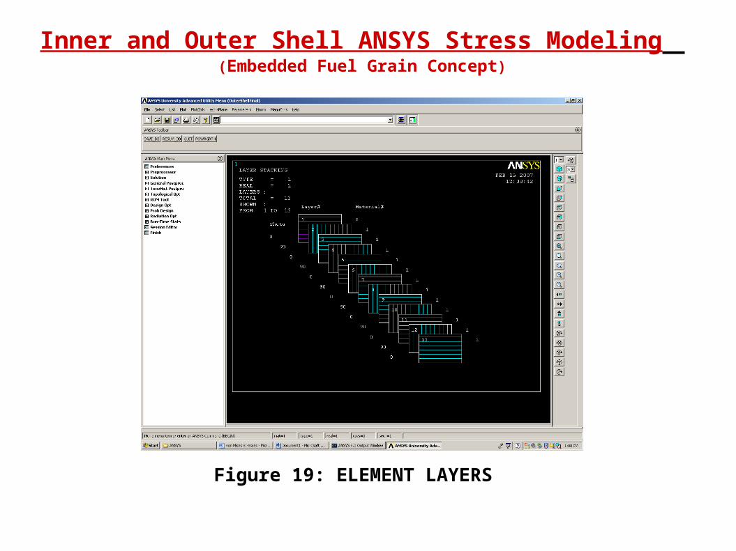
Inner and Outer Shell ANSYS Stress Modeling (Embedded Fuel Grain Concept)
Figure 19: ELEMENT LAYERS
Inner and Outer Shell ANSYS Stress Modeling (Embedded Fuel Grain Concept)
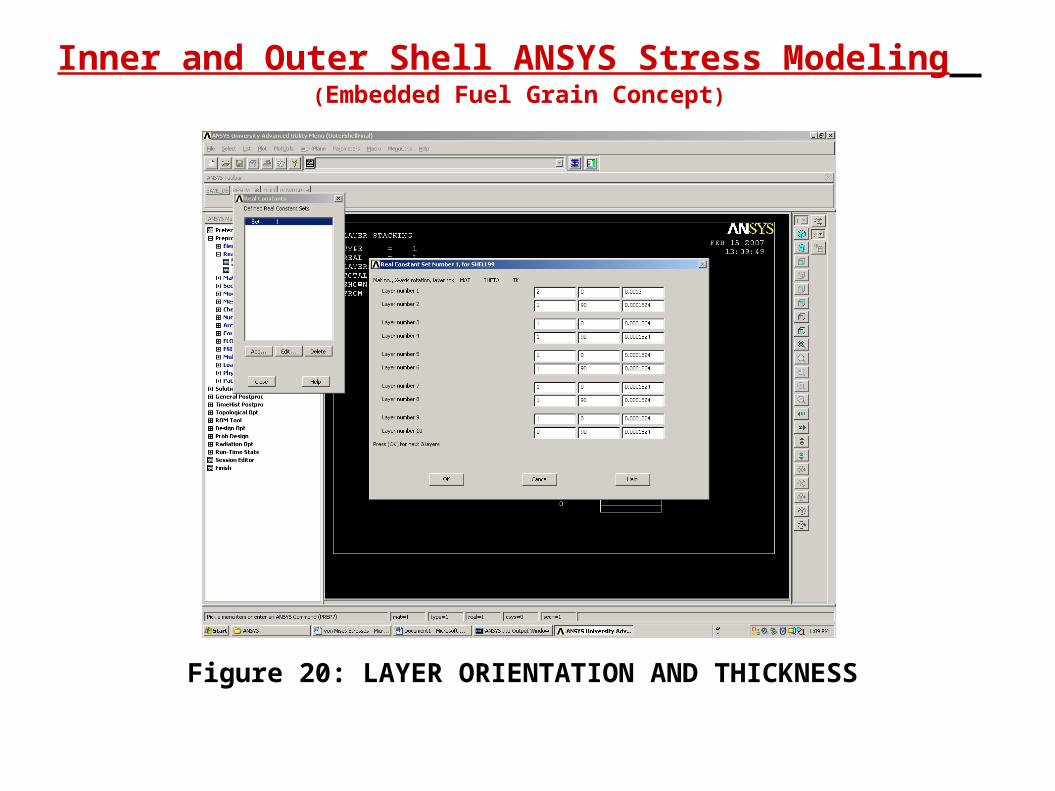
Figure 20: LAYER ORIENTATION AND THICKNESS
Inner and Outer Shell ANSYS Stress Modeling (Embedded Fuel Grain Concept)
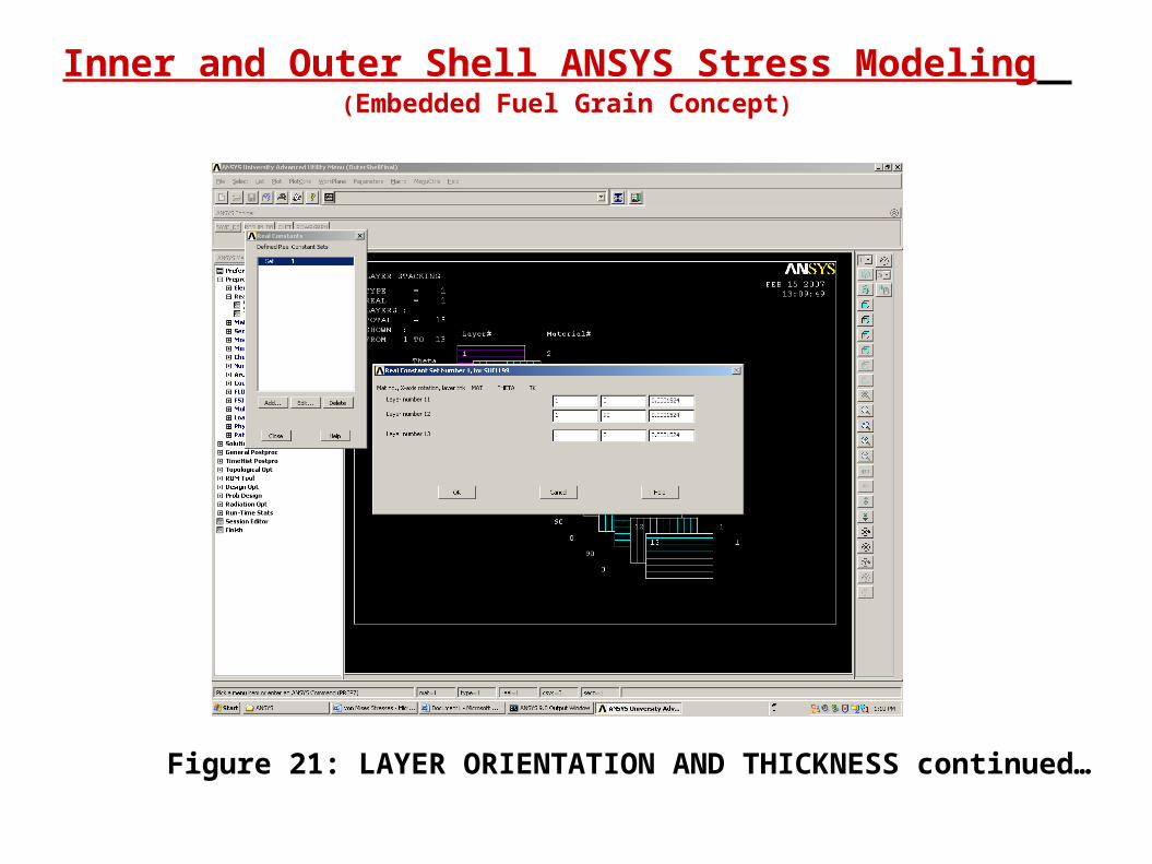
Figure 21: LAYER ORIENTATION AND THICKNESS continued…
Inner and Outer Shell ANSYS Stress Modeling (Embedded Fuel Grain Concept)
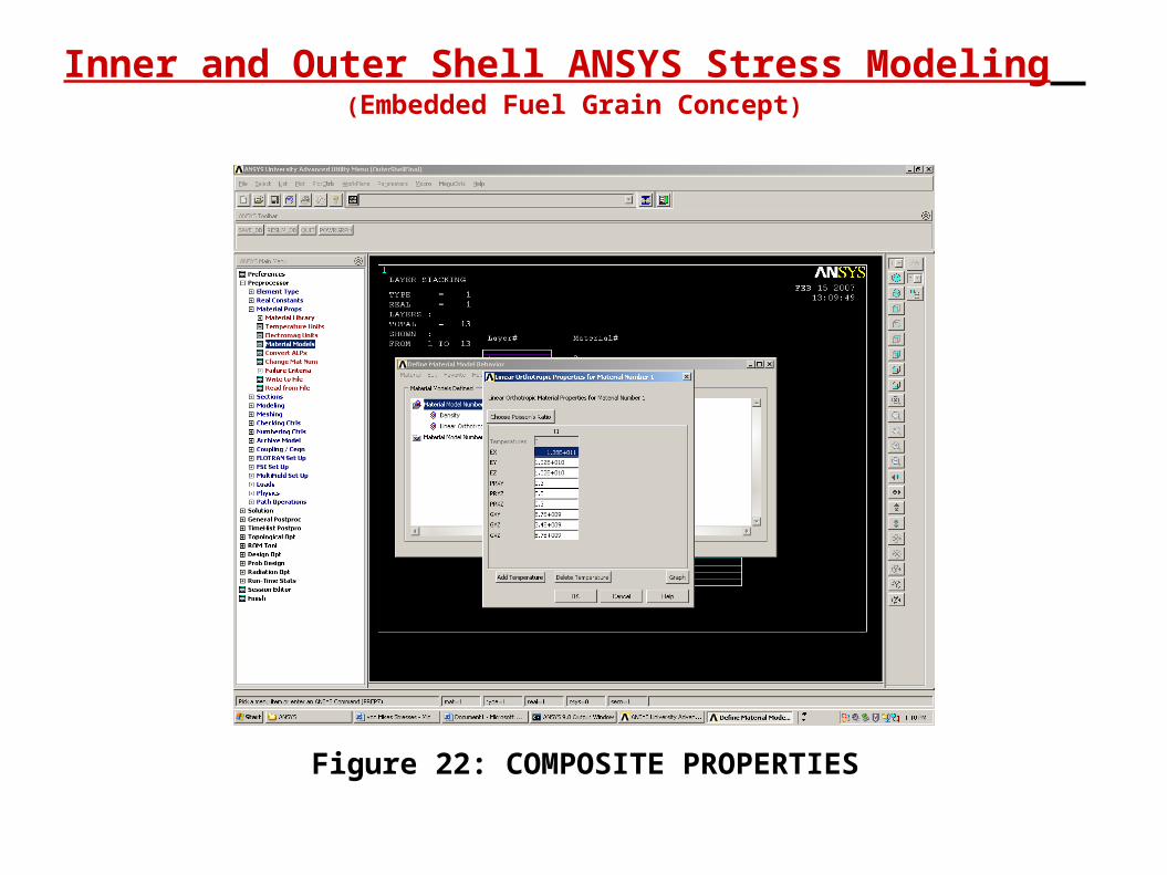
Figure 22: COMPOSITE PROPERTIES
Inner and Outer Shell ANSYS Stress Modeling (Embedded Fuel Grain Concept)
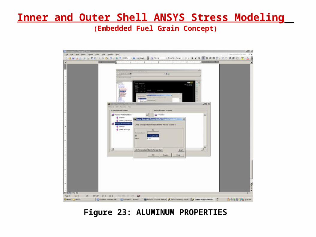
Figure 23: ALUMINUM PROPERTIES

Inner and Outer Shell ANSYS Stress Modeling (Embedded Fuel Grain Concept)
Figure 24: FAILURE CRITERIA FOR COMPOSITES
Inner and Outer Shell ANSYS Stress Modeling (Embedded Fuel Grain Concept)
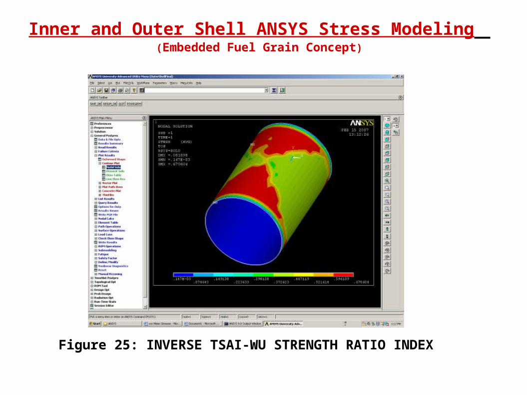
Figure 25: INVERSE TSAI-WU STRENGTH RATIO INDEX
Inner and Outer Shell ANSYS Stress Modeling (Embedded Fuel Grain Concept)
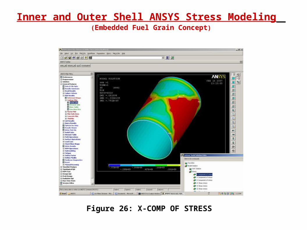
Figure 26: X-COMP OF STRESS
Inner and Outer Shell ANSYS Stress Modeling (Embedded Fuel Grain Concept)
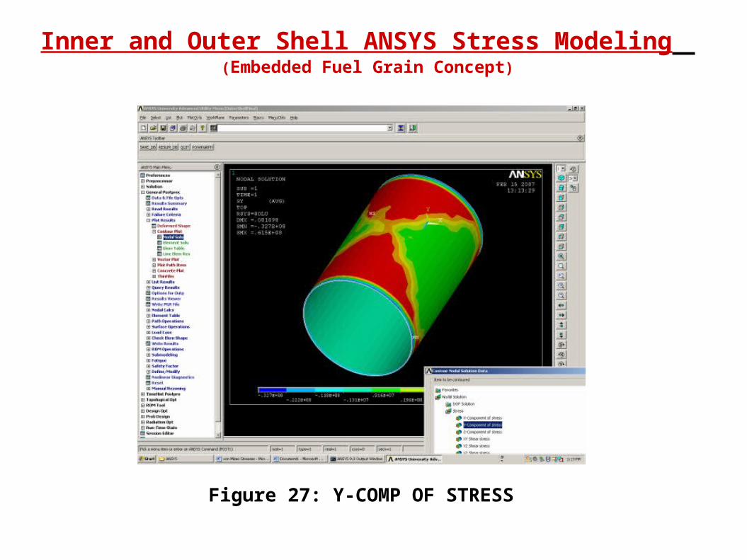
Figure 27: Y-COMP OF STRESS
Inner and Outer Shell ANSYS Stress Modeling (Embedded Fuel Grain Concept)
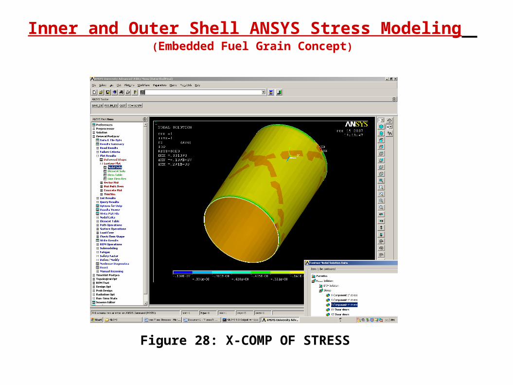
Figure 28: X-COMP OF STRESS
Inner and Outer Shell ANSYS Stress Modeling (Embedded Fuel Grain Concept)
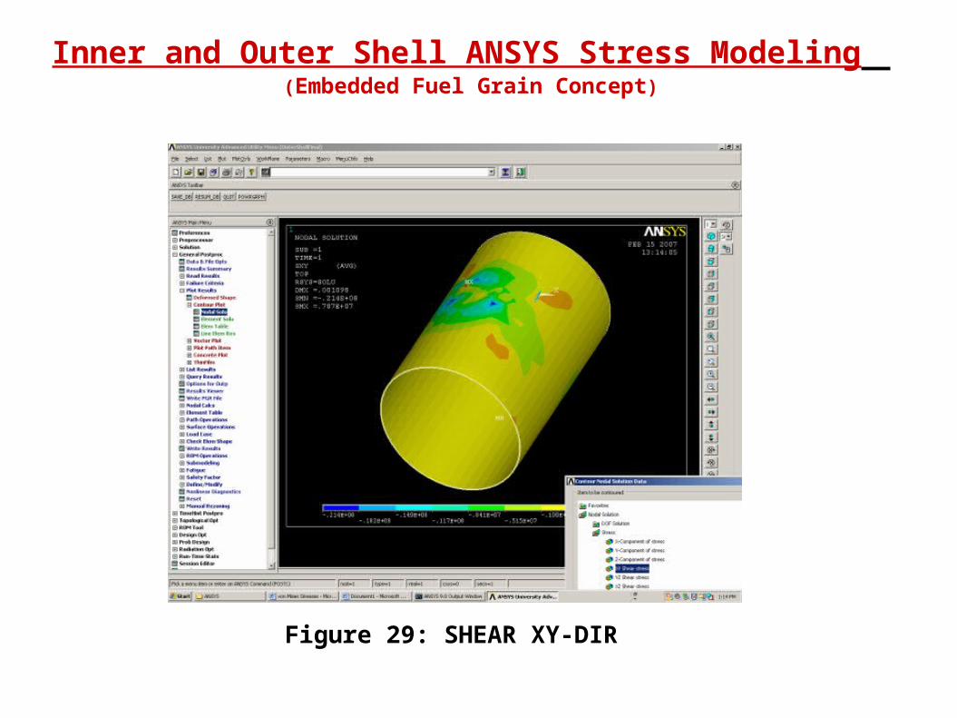
Figure 29: SHEAR XY-DIR
Inner and Outer Shell ANSYS Stress Modeling (Embedded Fuel Grain Concept)
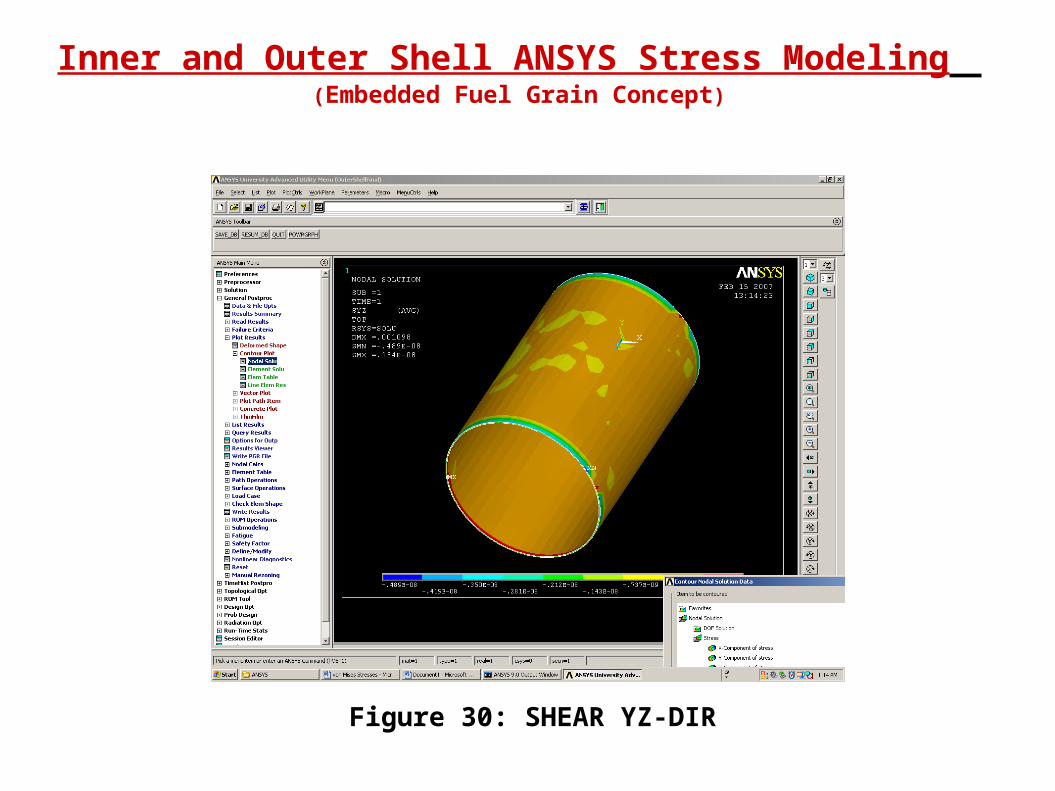
Figure 30: SHEAR YZ-DIR
Inner and Outer Shell ANSYS Stress Modeling (Embedded Fuel Grain Concept)
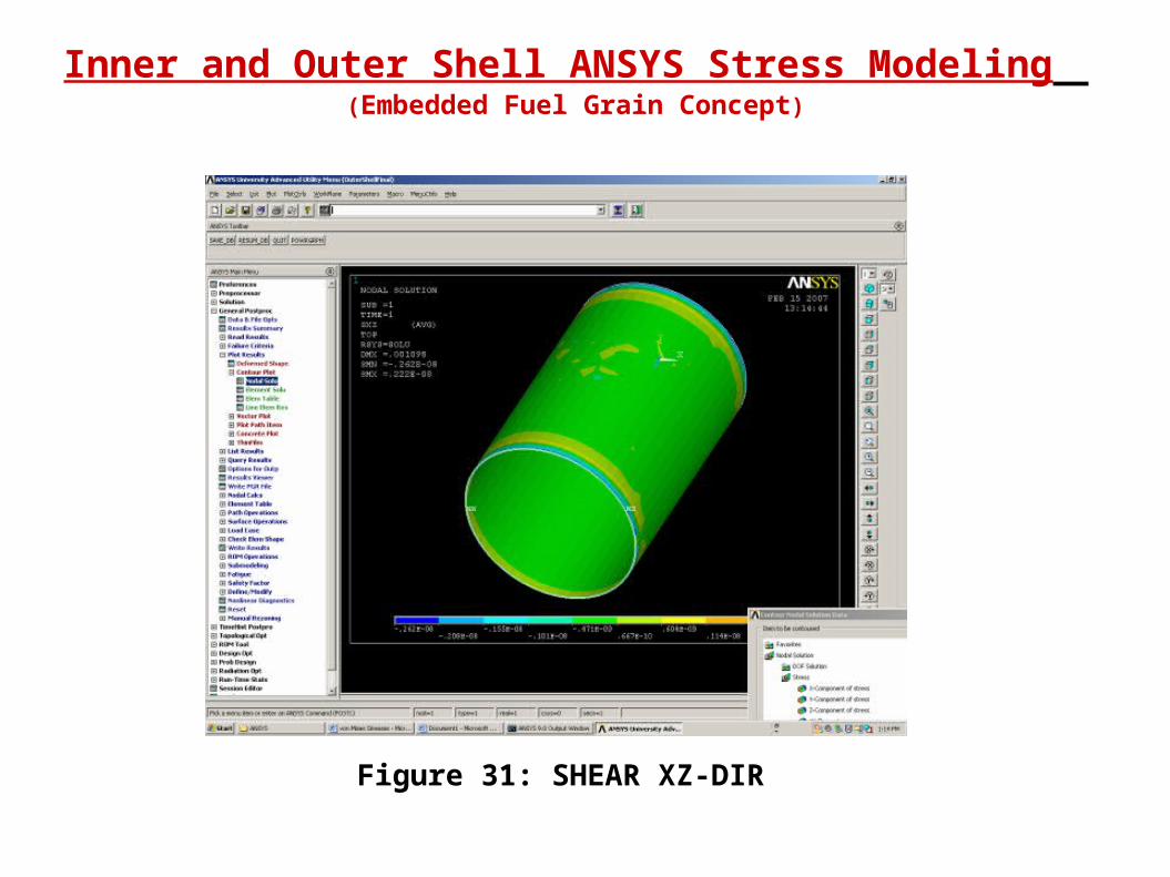
Figure 31: SHEAR XZ-DIR
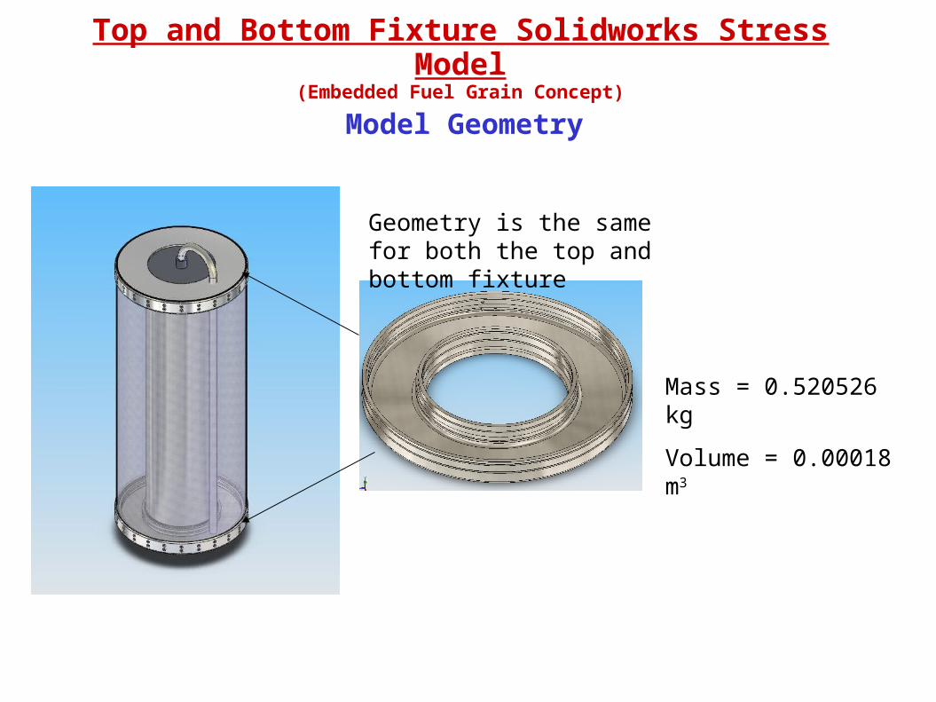
Top and Bottom Fixture Solidworks Stress Model(Embedded Fuel Grain Concept)
Model Geometry
Mass = 0.520526 kg
Volume = 0.00018 m3
Geometry is the same for both the top and bottom fixture
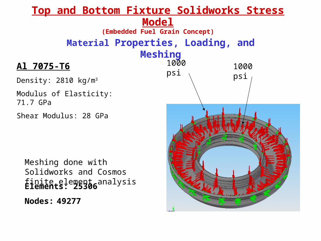
Material Properties, Loading, and Meshing
Al 7075-T6
Density: 2810 kg/m3
Modulus of Elasticity: 71.7 GPa
Shear Modulus: 28 GPa
Top and Bottom Fixture Solidworks Stress Model(Embedded Fuel Grain Concept)
1000 psi 1000 psi
Meshing done with Solidworks and Cosmos finite element analysis
Elements: 25306
Nodes: 49277
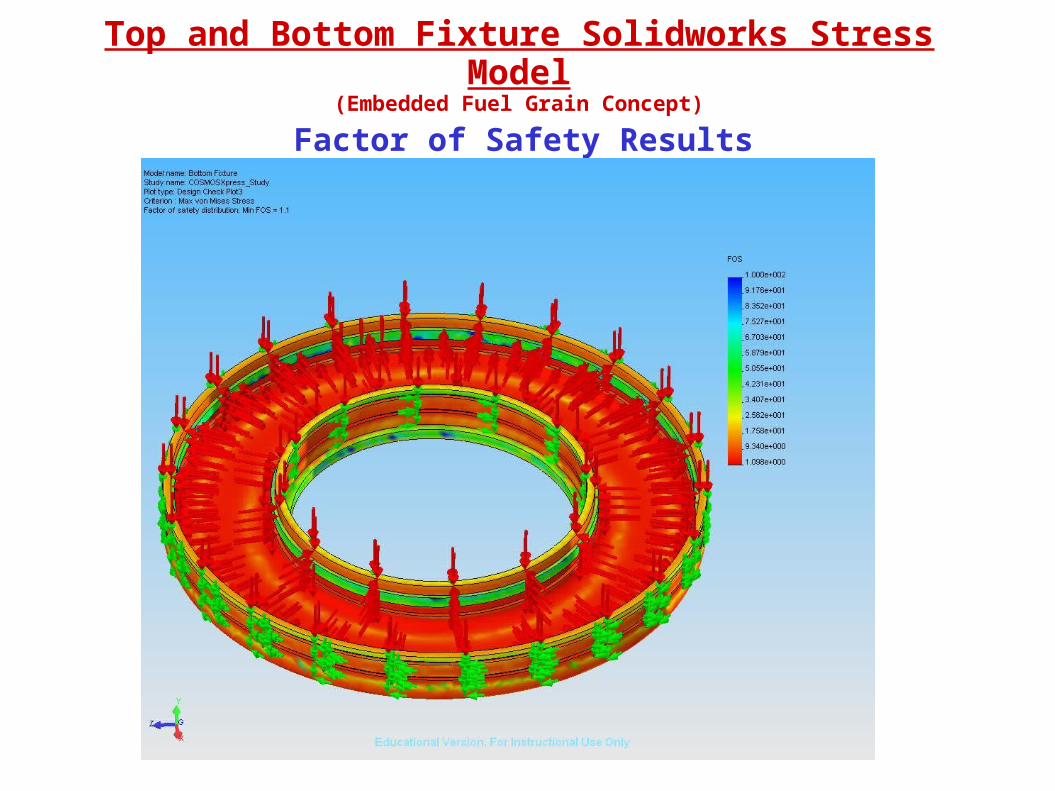
Factor of Safety Results
Top and Bottom Fixture Solidworks Stress Model(Embedded Fuel Grain Concept)
Discussion of Results
•This model demonstrates how the top and bottom fixtures will hold up against the required loads. The loading is purely theoretical at this point, but the model is made, and all that needs to be done is substitute the correct loads for the theoretical ones.
Top and Bottom Fixture Solidworks Stress Model(Embedded Fuel Grain Concept)
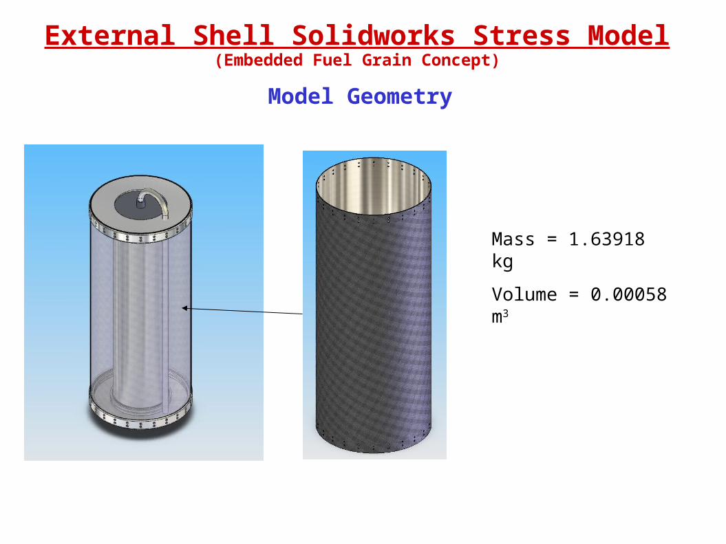
External Shell Solidworks Stress Model(Embedded Fuel Grain Concept)
Model Geometry
Mass = 1.63918 kg
Volume = 0.00058 m3
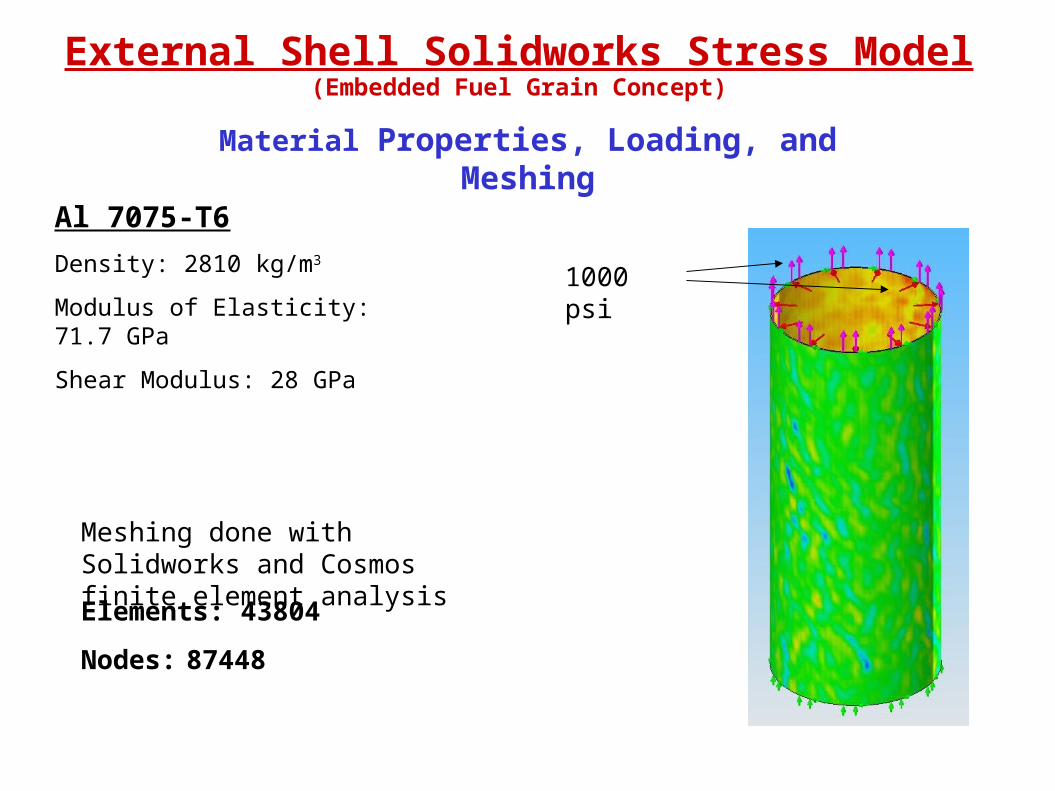
Material Properties, Loading, and Meshing
Meshing done with Solidworks and Cosmos finite element analysis
Elements: 43804
Nodes: 87448
External Shell Solidworks Stress Model(Embedded Fuel Grain Concept)
1000 psi
Al 7075-T6
Density: 2810 kg/m3
Modulus of Elasticity: 71.7 GPa
Shear Modulus: 28 GPa

Factor of Safety Results
External Shell Solidworks Stress Model(Embedded Fuel Grain Concept)

Discussion of Results
External Shell Solidworks Stress Model(Embedded Fuel Grain Concept)
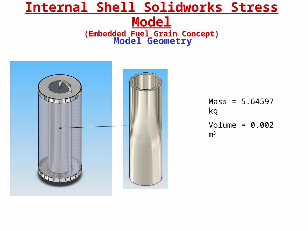
Internal Shell Solidworks Stress Model(Embedded Fuel Grain Concept)
Model Geometry
Mass = 5.64597 kg
Volume = 0.002 m3

Material Properties, Loading, and Meshing
Al 2024
Density: 2780 kg/m3
Modulus of Elasticity: 73.1 GPa
Shear Modulus: 28 GPa
Meshing done with Solidworks and Cosmos finite element analysis
Elements: 34919
Nodes: 68256
Internal Shell Solidworks Stress Model(Embedded Fuel Grain Concept)
1000 psi
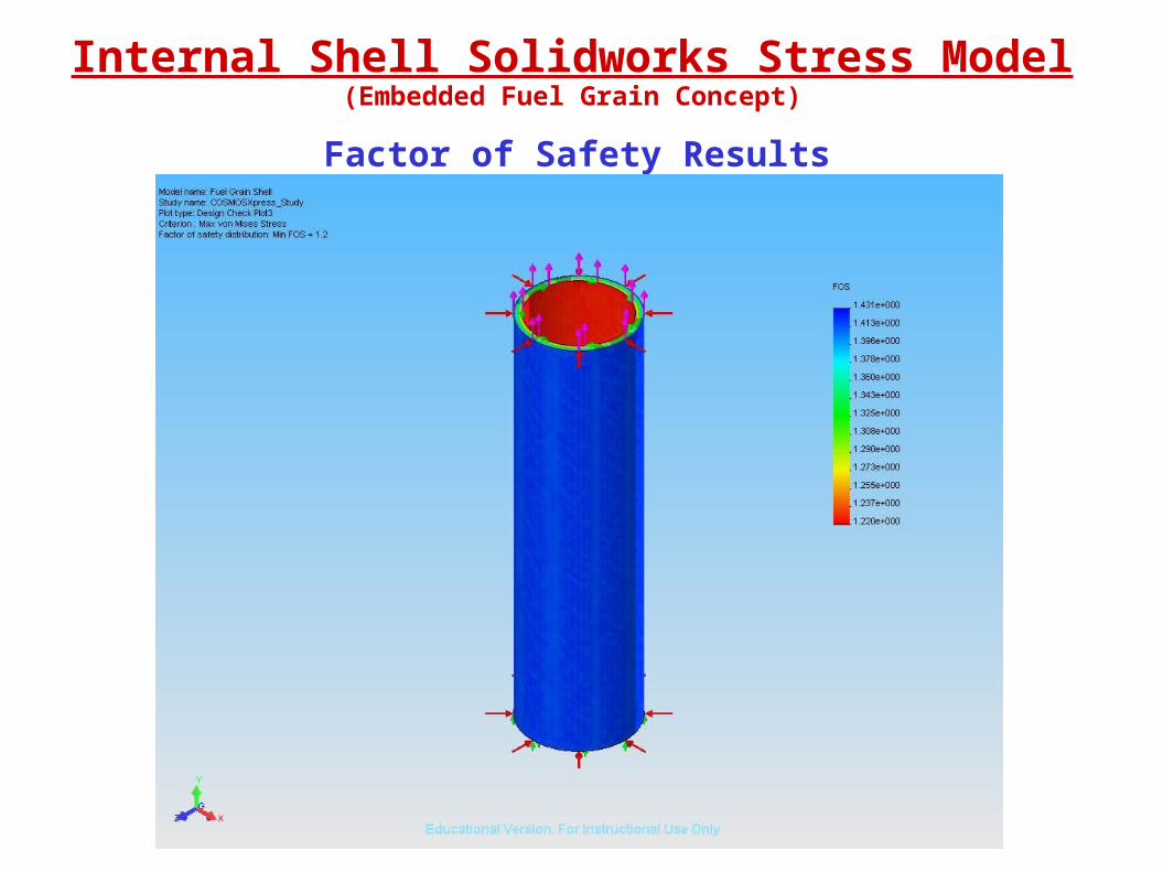
Factor of Safety Results
Internal Shell Solidworks Stress Model(Embedded Fuel Grain Concept)
Discussion of Results
Internal Shell Solidworks Stress Model(Embedded Fuel Grain Concept)

Al2O3 Post Combustion Chamber
Post Combustion Chamber ANSYS Thermal Model (Embedded Fuel Grain Concept)
Outer radius: 1.25” (0.03175 m)
Inner radius: 1” (0.0254 m)
Height: 1.5” (0.0381 m)
Outer radius: 1.75” + 0.5 mm (0.03225 m)
Inner radius: 1.25” (0.03175 m)
Height: 1.5” (0.0381 m)
Al 7075-T6 Housing (0.5 mm)
Model Geometry
Post Combustion Chamber ANSYS Thermal Model (Embedded Fuel Grain Concept)
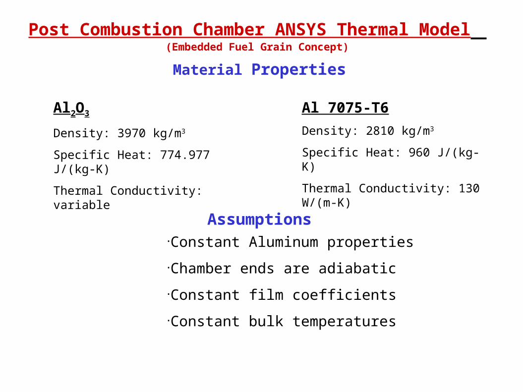
Material Properties
Al2O3
Density: 3970 kg/m3
Specific Heat: 774.977 J/(kg-K)
Thermal Conductivity: variable
Al 7075-T6
Density: 2810 kg/m3
Specific Heat: 960 J/(kg-K)
Thermal Conductivity: 130 W/(m-K)
Assumptions•Constant Aluminum properties
•Chamber ends are adiabatic
•Constant film coefficients
•Constant bulk temperatures

Post Combustion Chamber ANSYS Thermal Model (Embedded Fuel Grain Concept)
Meshed Model
Nodes: 9,589
Elements: 5,602
Volumes meshed using ANSYS SmartSize 1 with tetrahedral elements
Post Combustion Chamber ANSYS Thermal Model (Embedded Fuel Grain Concept)
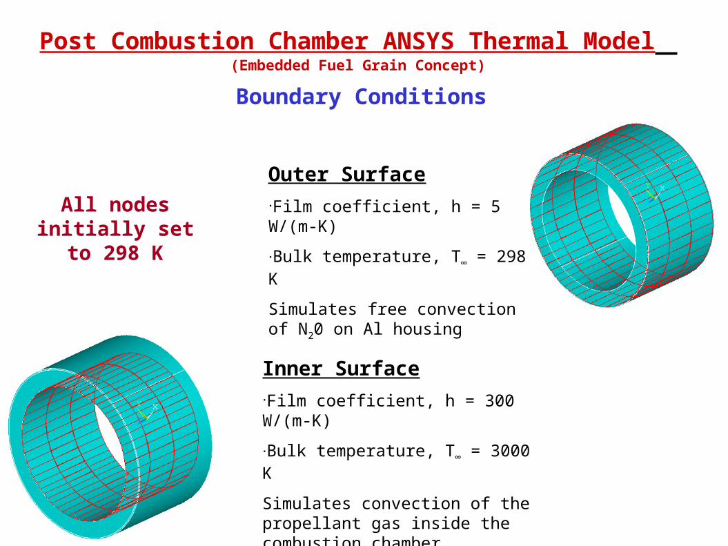
Boundary Conditions
Outer Surface•Film coefficient, h = 5 W/(m-K)
•Bulk temperature, T∞ = 298 K
Simulates free convection of N20 on Al housing
Inner Surface•Film coefficient, h = 300 W/(m-K)
•Bulk temperature, T∞ = 3000 K
Simulates convection of the propellant gas inside the combustion chamber
All nodes initially set to 298 K

Post Combustion Chamber ANSYS Thermal Model (Embedded Fuel Grain Concept)
Transient Results1
MN
MX
X
Y
Z
Model of Post Combustion Chamber and Al Housing
15391567
15941622
16501677
17051733
17601788
FEB 13 200719:27:23
NODAL SOLUTION
STEP=1SUB =101TIME=50TEMP (AVG)RSYS=0SMN =1539SMX =1788
Post Combustion Chamber ANSYS Thermal Model (Embedded Fuel Grain Concept)
Discussion of Results
•This model demonstrates heat transfer across multiple ANSYS volumes, which will be necessary to derive a film coefficient from thermocouple data
•A transient analysis was also performed by hand using ANSYS input conditions with results matching ANSYS output to within 100 Kelvin. The transient model is considered validated for this test case.

Post Combustion Chamber ANSYS Thermal Model (Engine Core)
Future Models
A model of the post combustion chamber and nozzle is being developed to utilize data that will be collected by the test stand team.
The model will be used to back out an average film coefficient and to determine if the engine structure will meet the Guidance burn time of 50 seconds.