IDEC SmartRelays LONWORKS Communication Modules Manual · LONWORKS® Communication Module User’s...
24
L ON W ORKS Communication Module User's Manual ® FL9Y-B695
Transcript of IDEC SmartRelays LONWORKS Communication Modules Manual · LONWORKS® Communication Module User’s...
FL9Y-B695
LONWORKS Communication Module
User's Manual
®

LONWORKS® Communication Module User’s Manual i
Indicates that death or severebodily injury may occur, if thecorresponding safety measuresare not taken.
Safety Notices
DANGER
WARNING
CAUTION
CAUTION
WARNING
Indicates that death, severe bodilyinjury or substantial material damagewill occur, if the corresponding safetymeasures are not taken.
With the warning triangle, thisindicates that minor bodilyinjury may occur, if thecorresponding safety measuresare not taken.
Without the warning triangle,this indicates that materialdamage may occur, if thecorresponding safety measuresare not taken.
This indicates that an undesirableresult or condition may occur, if thecorresponding instructions are notobserved.
Phone: 800.894.0412 - Fax: 888.723.4773 - Web: www.clrwtr.com - Email: [email protected]

LONWORKS® Communication Module User’s Manual ii
Copyright © IDEC IZUMI CORPORATION All rights reservedYou may not transfer or duplicate this document or utilize or reveal its contents,unless expressly authorized in writing. In the case of a violation, you will be obligedto pay damages. All rights reserved, in particular in the event that a patent isgranted or that a utility model is registered.Disclaimer of liability:We have checked that the contents of this document correctly describe theassociated hardware and software. Nonetheless, it is impossible to exclude thepossibility of deviations and therefore we cannot guarantee that there are no errorsin this document. The information in this document is checked regularly and anynecessary corrections are then made in the next release issued. We are of coursethankful for any suggestions for improvements.
Phone: 800.894.0412 - Fax: 888.723.4773 - Web: www.clrwtr.com - Email: [email protected]

LONWORKS® Communication Module User’s Manual iii
Table of Contents
1. Getting to know LONWORKS® Communication Module..... 1-1
1.1 What is LONWORKS® Communication Module ? ................... 1-1
1.2 The construction of the LONWORKS® Communication Module1-2
2. Mounting and wiring the LONWORKS® Communication Module…2-1
2.1 General guidelines .................................................................... 2-1
2.2 Wiring the LONWORKS® Communication Module .................. 2-32.2.1 Connecting the power supply ................................................... 2-42.2.2 Connecting the LON................................................................. 2-5
3. Putting the LONWORKS® Communication Module into operation 3-1
3.1 Step-by-step.............................................................................. 3-1
3.2 The LONWORKS® Communication Module - operational status3-2
3.3 Behavior in case of a fault ......................................................... 3-3
4. Supported functions.................................................................... 4-1
4.1 Virtual inputs / outputs............................................................... 4-1
4.2 Available network variables ....................................................... 4-3
4.3 LON configuration parameters .................................................. 4-5
4.4 Inputs / Outputs – special considerations .................................. 4-6
4.5 Alias table entries...................................................................... 4-6
5. LONWORKS® Communication Module - Specifications ....... 5-1
Phone: 800.894.0412 - Fax: 888.723.4773 - Web: www.clrwtr.com - Email: [email protected]

LONWORKS® Communication Module User’s Manual 1-1
1. Getting to know LONWORKS® Communication Module
1.1 What is LONWORKS® CommunicationModule ?The Local Operating Network (LONWORKS® CommunicationModule) communications module is an interface forconnecting IDEC SmartRelay onto a LON network.The IDEC SmartRelay communications module has beenimplemented as a Slave module for the IDEC SmartRelaycontrol module.The module supports communication between the IDECSmartRelay Master and external LON devices via a LON.The LONWORKS® Communication Module is a bus station onthe LON and allows the IDEC SmartRelay to communicatewith other LON devices.
What are the capabilities of the LONWORKS®Communication Module ?The LONWORKS® Communication Module presents thecurrent states of the LON stations to the IDEC SmartRelay,which is thus able to use its logical functions and timers tojoin them together. In the process, the LON signals can alsobe combined with the signals of the local IDEC SmartRelayinputs and outputs. The LONWORKS® CommunicationModule then transmits every change of the output signal viathe LON.
The combination of IDEC SmartRelay and LONWORKS®Communication Module gives the user a decentralizedcontroller functionality for the LON with the capability ofsetting or changing parameters or operations quickly, simplyand without a programming device.
Phone: 800.894.0412 - Fax: 888.723.4773 - Web: www.clrwtr.com - Email: [email protected]
LONWORKS® Communication Module User’s Manual 1-2
1.2 The construction of the LONWORKS®Communication Module
Phone: 800.894.0412 - Fax: 888.723.4773 - Web: www.clrwtr.com - Email: [email protected]

LONWORKS® Communication Module User’s Manual 1-3
1. Power supply2. Bus lock slider, interface to the IDEC SmartRelay3. The RUN/STOP LED for IDEC SmartRelay
communication4. The SERVICE LED5. Input - LON connection6. Expansion interface to the IDEC SmartRelay7. Mechanical coding - pin8. Service button
7
8
1
3
4
5
6
2
Phone: 800.894.0412 - Fax: 888.723.4773 - Web: www.clrwtr.com - Email: [email protected]
LONWORKS® Communication Module User’s Manual 2-1
2. Mounting and wiring the LONWORKS®Communication Module
2.1 General guidelinesThe following guidelines should be observed when mountingwiring your LONWORKS® Communication Module:- When wiring the LONWORKS® Communication Module,
make certain that you follow all of the applicable andlegally binding standards. Observe all of the relevantnational and regional regulations when installing andoperating the device. Check with the local authoritiesregarding the standards and regulations that must beobserved in your special case.
- Make certain that the device is de-energized.- Use only approved bus cables.- Make certain that the specified cable lengths are used and
that the correct terminating resistors are installed properly.- The LONWORKS® Communication Module must always
be installed as the last module on the right of the IDECSmartRelay, since you may not install other expansionmodules onto the LONWORKS® Communication Module.
Phone: 800.894.0412 - Fax: 888.723.4773 - Web: www.clrwtr.com - Email: [email protected]

LONWORKS® Communication Module User’s Manual 2-2
Please notice:- The LONWORKS® Communication Module must have its
own power supply (24 V AC/DC).
NOTE
This module may only be mounted and wired by qualifiedpersonnel, who know and observe the generally applicableguidelines and applicable regulations and standards.
Observe the assembly and disassembly instructions in theIDEC SmartRelay manual.
WARNINGThe expansion module may only inserted or removed whenthe power is off.
Phone: 800.894.0412 - Fax: 888.723.4773 - Web: www.clrwtr.com - Email: [email protected]
LONWORKS® Communication Module User’s Manual 2-3
2.2 Wiring the LONWORKS® CommunicationModuleTo wire the LONWORKS® Communication Module, use ascrewdriver with 3 mm wide blade.- You do not need to use wire end ferrules when clamping
the wires.
NOTE
After the installation, the terminals must be covered. Toprotect personnel against unintentional contact with theportions of the LONWORKS® Communication Module thatare conducting electricity, the appropriate national and localstandards must be observed.
The LONWORKS® Communication Module is a double-insulated switching device.A protective grounding conductor is not necessary.
Phone: 800.894.0412 - Fax: 888.723.4773 - Web: www.clrwtr.com - Email: [email protected]
LONWORKS® Communication Module User’s Manual 2-4
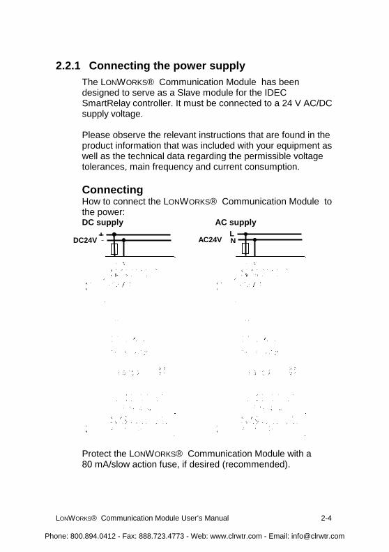
2.2.1 Connecting the power supplyThe LONWORKS® Communication Module has beendesigned to serve as a Slave module for the IDECSmartRelay controller. It must be connected to a 24 V AC/DCsupply voltage.
Please observe the relevant instructions that are found in theproduct information that was included with your equipment aswell as the technical data regarding the permissible voltagetolerances, main frequency and current consumption.
ConnectingHow to connect the LONWORKS® Communication Module tothe power:DC supply AC supply
Protect the LONWORKS® Communication Module with a80 mA/slow action fuse, if desired (recommended).
+-DC24VLNAC24V
Phone: 800.894.0412 - Fax: 888.723.4773 - Web: www.clrwtr.com - Email: [email protected]
LONWORKS® Communication Module User’s Manual 2-5
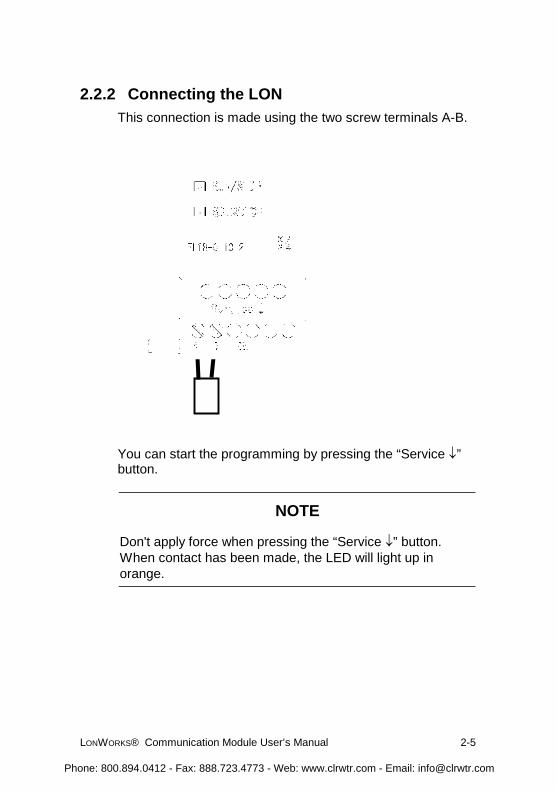
2.2.2 Connecting the LONThis connection is made using the two screw terminals A-B.
You can start the programming by pressing the “Service �”button.
NOTE
Don't apply force when pressing the “Service �” button.When contact has been made, the LED will light up inorange.
Phone: 800.894.0412 - Fax: 888.723.4773 - Web: www.clrwtr.com - Email: [email protected]

LONWORKS® Communication Module User’s Manual 3-1
3. Putting the LONWORKS® CommunicationModule into operationA LONMARK certified application was loaded into the LONmodule at the factory.
3.1 Step-by-step1. Interrupt the voltage to the IDEC SmartRelay.
(The IDEC SmartRelay and its modules do not havepower switches.)
2. Mount the LONWORKS® Communication Module3. Connect the power supply to the LONWORKS®
Communication Module.4. Connect the LON bus lines to the LONWORKS®
Communication Module.5. Remove the label with the Neuron-ID from the
LONWORKS® Communication Module and stick it on thenetwork plan at the LONWORKS® CommunicationModule's installed location. (The Neuron-ID is also givenas a bar code on the label.)
6. Apply power to the IDEC SmartRelay and LONWORKS®Communication Module.
7. If multiple LONWORKS® Communication Modules havebeen installed, repeat Steps 1 to 6 for each LONWORKS®Communication Module.
8. To log a LONWORKS® Communication Module in on aLON network, you can either press the “Service” buttonor enter the Neuron-ID directly in the LON using theInstallation Tool or by reading the label with a bar codescanner.
9. The LONWORKS® Communication Module is thenregistered in the LON database and ready for operation.
10. For further details regarding the LON installation, pleaseread the corresponding documentation.
Phone: 800.894.0412 - Fax: 888.723.4773 - Web: www.clrwtr.com - Email: [email protected]

LONWORKS® Communication Module User’s Manual 3-2
3.2 The LONWORKS® Communication Module -operational statusThe LONWORKS® Communication Module is a IDECSmartRelay expansion module. This module has two LEDdisplays:“RUN/STOP” LED Communication with the IDEC
SmartRelay“SERVICE” LED Service LED
LED “RUN/STOP” Lights InGreen (RUN) Red (STOP) Orange
The LONWORKS®CommunicationModule iscommunicating withthe device on the left.
The LONWORKS®Communication Moduleis not communicatingwith the device on theleft.
The LONWORKS®CommunicationModule 's initializationphase
LED “SERVICE” Lights InGreen Red Orange Green /Orange
FlashingConfigure “Service”
button pressedTheLONWORKS®CommunicationModule 'sinitializationphase
Unconfigure
Phone: 800.894.0412 - Fax: 888.723.4773 - Web: www.clrwtr.com - Email: [email protected]
LONWORKS® Communication Module User’s Manual 3-3
3.3 Behavior in case of a fault
IDEC SmartRelay - Power failureIf the power to the IDEC SmartRelay fails or thecommunications with the IDEC SmartRelay Master or thecommunications partner to the left is interrupted, the outputswill be set to 0. The “RUN/STOP” LED will light in RED afterone second.
IDEC SmartRelay - Power returnsThe IDEC SmartRelay will startup and the LONWORKS®Communication Module will send the parameterized status.
LONWORKS® Communication Module - Power failureAll of the inputs of the LONWORKS® Communication Modulewill be set by the IDEC SmartRelay Master to 0.
LONWORKS® Communication Module - Power returnsAll of the IDEC SmartRelay Master outputs will be updated.
Phone: 800.894.0412 - Fax: 888.723.4773 - Web: www.clrwtr.com - Email: [email protected]

LONWORKS® Communication Module User’s Manual 4-1
4. Supported functionsThe LONWORKS® Communication Module handles thecommunications between:
- The IDEC SmartRelay and LON- Supports virtual inputs and outputs for the
communication via the LON.
4.1 Virtual inputs / outputsThe standard LONWORKS® Communication Moduleapplication fills the complete IDEC SmartRelay processimage.
I9 I10 I11 I12
Q1 Q2 Q3 Q4 Q5 Q6 Q7 Q8 A 1 A2
Q9 ... Q16
FL1B-H12RCE FL1B-M08B2R2 FL1B-M08B2R2 FL1B-CL1C12
FL1B-H12RCE FL1B-CL1C12
A1 A2
A3 ... A8I9 ... I24Q5 ... Q16
LON
LON
I1 I2 I3 I4 I5 I6 I7 I8
Q1 Q2 Q3 Q4
A3 ... A8I13 ... I24
I1 I2 I3 I4 I5 I6 I7 I8
Phone: 800.894.0412 - Fax: 888.723.4773 - Web: www.clrwtr.com - Email: [email protected]
LONWORKS® Communication Module User’s Manual 4-2
I1
I9 Q9
I14
Q16
Q6
Q1 I13
Q1 Q2 Q3 Q4 Q5 Q6 Q7 Q8
I1 I2 I3 I4 I5 I6 I7 I8 I9I10I11I12
1
2
3
I13 ... I24
Q9 ... Q16LON
&
FL1B-M08B2R2 FL1B-CL1C12
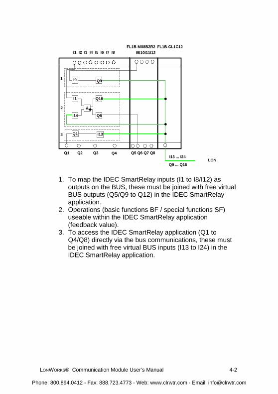
1. To map the IDEC SmartRelay inputs (I1 to I8/I12) asoutputs on the BUS, these must be joined with free virtualBUS outputs (Q5/Q9 to Q12) in the IDEC SmartRelayapplication.
2. Operations (basic functions BF / special functions SF)useable within the IDEC SmartRelay application(feedback value).
3. To access the IDEC SmartRelay application (Q1 toQ4/Q8) directly via the bus communications, these mustbe joined with free virtual BUS inputs (I13 to I24) in theIDEC SmartRelay application.
Phone: 800.894.0412 - Fax: 888.723.4773 - Web: www.clrwtr.com - Email: [email protected]

LONWORKS® Communication Module User’s Manual 4-3
4.2 Available network variablesThe LONWORKS® Communication Module’s standard LONapplication contains the network variables described below.
LonMark Node ObjectQuantity Name Type Description
1 nviRequest0 SNVT_obj_request Request object mode1 nvoStatus0 SNVT_obj_status Output object status
LonMark Controller ObjectSNVT DescriptionSNVT_switch Switch light, alarm, window contact, free inputs / outputs
value=0, state=0 � inactivevalue>0, state=1 � active
SNVT_occupancy Occupancy:0=occupied� 0 1=not occupied � 1
2=bypass � 0 3=standby � 1
SNVT_tod_event Scheduler programJust current state: 0=occupied
3=standbySNVT_temp_p Room temperatureSNVT_lux Brightness – lighting levelSNVT_lev_percent Position
Phone: 800.894.0412 - Fax: 888.723.4773 - Web: www.clrwtr.com - Email: [email protected]
LONWORKS® Communication Module User’s Manual 4-4
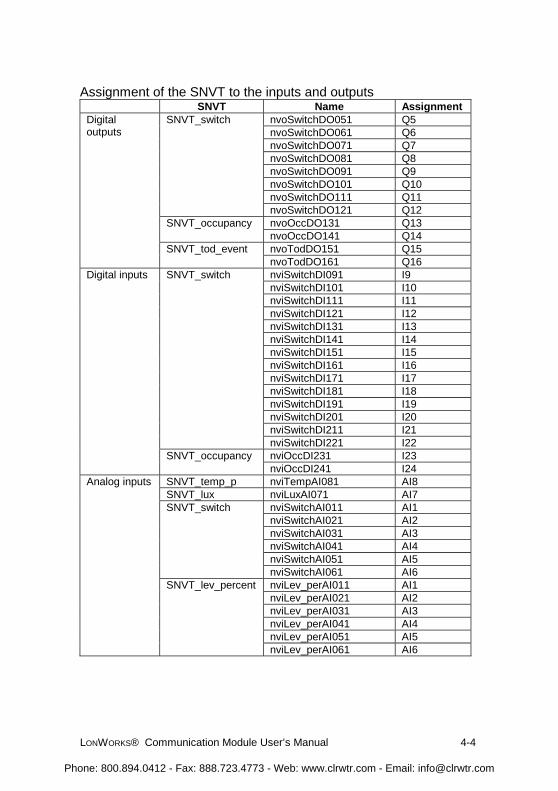
Assignment of the SNVT to the inputs and outputsSNVT Name Assignment
nvoSwitchDO051 Q5nvoSwitchDO061 Q6nvoSwitchDO071 Q7nvoSwitchDO081 Q8nvoSwitchDO091 Q9nvoSwitchDO101 Q10nvoSwitchDO111 Q11
SNVT_switch
nvoSwitchDO121 Q12nvoOccDO131 Q13SNVT_occupancynvoOccDO141 Q14nvoTodDO151 Q15
Digitaloutputs
SNVT_tod_eventnvoTodDO161 Q16nviSwitchDI091 I9nviSwitchDI101 I10nviSwitchDI111 I11nviSwitchDI121 I12nviSwitchDI131 I13nviSwitchDI141 I14nviSwitchDI151 I15nviSwitchDI161 I16nviSwitchDI171 I17nviSwitchDI181 I18nviSwitchDI191 I19nviSwitchDI201 I20nviSwitchDI211 I21
SNVT_switch
nviSwitchDI221 I22nviOccDI231 I23
Digital inputs
SNVT_occupancynviOccDI241 I24
SNVT_temp_p nviTempAI081 AI8SNVT_lux nviLuxAI071 AI7
nviSwitchAI011 AI1nviSwitchAI021 AI2nviSwitchAI031 AI3nviSwitchAI041 AI4nviSwitchAI051 AI5
SNVT_switch
nviSwitchAI061 AI6nviLev_perAI011 AI1nviLev_perAI021 AI2nviLev_perAI031 AI3nviLev_perAI041 AI4nviLev_perAI051 AI5
Analog inputs
SNVT_lev_percent
nviLev_perAI061 AI6
Phone: 800.894.0412 - Fax: 888.723.4773 - Web: www.clrwtr.com - Email: [email protected]
LONWORKS® Communication Module User’s Manual 4-5
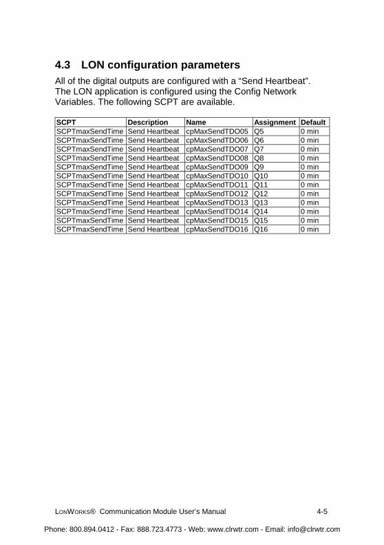
4.3 LON configuration parametersAll of the digital outputs are configured with a “Send Heartbeat”.The LON application is configured using the Config NetworkVariables. The following SCPT are available.
SCPT Description Name Assignment DefaultSCPTmaxSendTime Send Heartbeat cpMaxSendTDO05 Q5 0 minSCPTmaxSendTime Send Heartbeat cpMaxSendTDO06 Q6 0 minSCPTmaxSendTime Send Heartbeat cpMaxSendTDO07 Q7 0 minSCPTmaxSendTime Send Heartbeat cpMaxSendTDO08 Q8 0 minSCPTmaxSendTime Send Heartbeat cpMaxSendTDO09 Q9 0 minSCPTmaxSendTime Send Heartbeat cpMaxSendTDO10 Q10 0 minSCPTmaxSendTime Send Heartbeat cpMaxSendTDO11 Q11 0 minSCPTmaxSendTime Send Heartbeat cpMaxSendTDO12 Q12 0 minSCPTmaxSendTime Send Heartbeat cpMaxSendTDO13 Q13 0 minSCPTmaxSendTime Send Heartbeat cpMaxSendTDO14 Q14 0 minSCPTmaxSendTime Send Heartbeat cpMaxSendTDO15 Q15 0 minSCPTmaxSendTime Send Heartbeat cpMaxSendTDO16 Q16 0 min
Phone: 800.894.0412 - Fax: 888.723.4773 - Web: www.clrwtr.com - Email: [email protected]
LONWORKS® Communication Module User’s Manual 4-6
4.4 Inputs / Outputs – special considerations
Allocating the IDEC SmartRelay inputs/outputsAll of the inputs/outputs, which are physically allocated on theIDEC SmartRelay or an expansion module, are not availablefor allocation as virtual inputs/outputs.Only the outputs on additional I/O modules can be issued inparallel to the LON.
Using the IDEC SmartRelay inputs / outputs onthe LONWORKS® Communication ModuleTo access the IDEC SmartRelay outputs (Q1 to Q4) directlyvia the bus communications, these must be joined in theIDEC SmartRelay application with free virtual BUS inputs.To map the IDEC SmartRelay inputs (I1 - I8) as outputs onthe BUS, these must be joined with free virtual BUS outputsin the IDEC SmartRelay application.
Feedback valueFeedback variables are required for status displays for avariety of applications (primarily lighting applications).These are not directly supported by the LONWORKS®Communication Module.However, an internal operation using IDEC SmartRelayinputs/outputs is enough to display the status information onthe IDEC SmartRelay.
4.5 Alias table entriesThe LONWORKS® Communication Module supports 8 aliastable entries.
Phone: 800.894.0412 - Fax: 888.723.4773 - Web: www.clrwtr.com - Email: [email protected]
LONWORKS® Communication Module User’s Manual 5-1
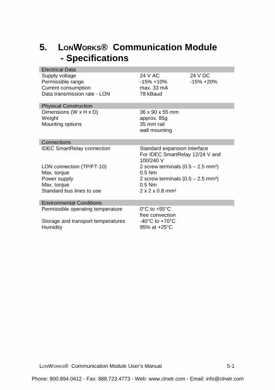
5. LONWORKS® Communication Module - Specifications
Electrical DataSupply voltage 24 V AC 24 V DCPermissible range -15% +10% -15% +20%Current consumption max. 33 mAData transmission rate - LON 78 kBaud
Physical ConstructionDimensions (W x H x D) 36 x 90 x 55 mmWeight approx. 85gMounting options 35 mm rail
wall mounting
ConnectionsIDEC SmartRelay connection Standard expansion interface
For IDEC SmartRelay 12/24 V and100/240 V
LON connection (TP/FT-10) 2 screw terminals (0.5 – 2.5 mm²)Max. torque 0.5 NmPower supply 2 screw terminals (0.5 – 2.5 mm²)Max. torque 0.5 NmStandard bus lines to use 2 x 2 x 0.8 mm²
Environmental ConditionsPermissible operating temperature 0°C to +55°C
free convectionStorage and transport temperatures -40°C to +70°CHumidity 95% at +25°C
Phone: 800.894.0412 - Fax: 888.723.4773 - Web: www.clrwtr.com - Email: [email protected]

LONWORKS® Communication Module User’s Manual 5-2
Safety
Protection standard IP 20Radio interference suppression EN 55011 (Limit Value Class B)Certification CE
UL 508VDE 0631IEC 61131-2
Overvoltage protectionFuse 80 mA slow action fuse
Order DataIDEC SmartRelay Expansion ModuleLONWORKS® Communication Module
FL1B-CL1C12
Phone: 800.894.0412 - Fax: 888.723.4773 - Web: www.clrwtr.com - Email: [email protected]
LONWORKS® Communication Module User’s Manual 6-1
6. IndexMechanical coding - pin ...... 1-3Power supply ....................... 1-3RUN/STOP LED.................. 1-3Service button...................... 1-3SERVICE LED .................... 1-3slider .................................... 1-3SNVT_lev_percent........ 4-3, 4-4
SNVT_lux.............................4-3SNVT_obj_request ...............4-3SNVT_obj_status .................4-3SNVT_occupancy ..........4-3, 4-4SNVT_switch ................4-3, 4-4SNVT_temp_p...............4-3, 4-4SNVT_tod_event ...........4-3, 4-4
Phone: 800.894.0412 - Fax: 888.723.4773 - Web: www.clrwtr.com - Email: [email protected]