
ide U ser’s g - Uniwatt |...
8
INSUAC0216 GLASS FRONT CONVECTOR REPLACEMENT COMPONENT LIST INCLUDED UAC S Y S T È M E Q U A L I T É C E R TIFIÉ - R E G IS T E R E D Q U A L I T Y S Y S T E M UNIWATT is a line of products manufactured by STELPRO. For more information please contact customer service. USER’S GUIDE This unit complies with CSA standards
Transcript of ide U ser’s g - Uniwatt |...

INSUAC0216
UACXX01
X:\01_PRODUITS\FAMILLES\UAC\DOCUMENTATION\UAC_ISO
N.DEFFINS
2015-12-14 / adesmarais2015-05-14
1 / 13rd ANGLE PROJECTION3e ANGLE DE PROJECTION
UACDESCRIPTION:
CRÉÉ PAR | CREATED BY:
CRÉÉ LE | CREATED ON:
# PIÈCE | PART #:
AFORMAT | SIZE:
FEUILLE | SHEET:XX.X° = ±0.5°
XX° = ±1°
.XXX = ±.015" [ ±.38mm]
CONSENT OF STELPRO DESIGN.
MIS À JOUR | UPDATED:
EMPLACEMENT:
TOLÉRANCES SI NON-SPÉCIFIÉES | TOLERANCES IF NOT SPECIFIED
LINÉAIRE | LINEAR: ANGULAIRE | ANGULAR:
.XX = ±.03" [ ±.76mm]
L'INFORMATION CONTENUE DANS CE DOCUMENT EST
LA PROPRIÉTÉ DE STELPRO DESIGN. EN AUCUN CAS,
L'INFORMATION NE PEUT ÊTRE UTILISÉE, SAUF SOUS
AUTORISATION ÉCRITE DE STELPRO DESIGN.
THE INFORMATION IN THIS DOCUMENT IS THE
PROPERTY OF STELPRO DESIGN. IN ANY CASE, THE
INFORMATION CAN'T BE USED, EXCEPT THE WRITTEN
MATÉRIEL | MATERIAL:
GLASS FRONT CONVECTORREpLACEmENT COmpONENT LiST iNCLudEd
UaCSY
STÈM
E Q
UAL
ITÉ CERTIFIÉ - REGISTERED QUALITY SYSTEM
UNIWATT is a line of products manufactured by STelpro. For more information please contact customer service.
Us
er
’s g
Uid
e
This unit complies with CSA standards

INSUAC02162
warningBefore installing and operating this product, the user and/or installer must read, understand and follow these instructions and keep them handy for future reference. If these instructions are not followed, the warranty will be considered null and void and the manufacturer deems no further responsibility for this product.
This product must be installed by a qualified person and connected by a certified electrician, according to the electrical and building codes effective in your region.
The following instructions must be adhered to in order to avoid personal injuries or property damages, serious injuries and potentially fatal electric shocks.
Protect the heating unit with the appropriate circuit breaker or fuse, in accordance with the nameplate.
Make sure the line voltage (volt) is consistent with that indicated on the unit’s nameplate.
Switch off the power at the circuit breaker/fuse before installing, repairing and cleaning the unit.
Make sure the unit is appropriate for the intended use (if needed, refer to the product catalog or a representative). Use this heater only as described in this manual. Any other use not recommended by the manufacturer may cause fire, electric shock, or injury to persons. Do not use outdoors.
Recommended heating capacity: 1.25 W/cubic foot (0.03 m³)It corresponds to 10 W/square foot (0.09 m²) based on a standard ceiling height of 8 feet (2.44 m). The recommended capacity is usually sufficient for normal heating needs. Please note that the insulation quality of walls and windows are some of the factors that influence heat losses, which modify the required capacity to heat a room. If needed, refer to a specialist who will be able to calculate these heat losses and optimize the required capacity or consult the “Online heating calculation” section of the Stelpro website (residential buildings). To heat a large room and to increase your comfort, it is recommended to install several units instead of one. For example, 2 X 1000 W rather than 1 X 2000 W.
Do not install the unit where objects or pieces of furniture could be heat damaged.
If the unit’s capacity is insufficient for the size of the room, it will be in operation continuously, and may become defective earlier and turn yellow.
Respect distances and positions indicated in the installation section.
If the installer or user modifies the unit, they will be held responsible for any damage resulting from this modification, and the CSA certification could be void.
This unit must not come into contact with a water source and must be protected from splashes (e.g. a wet mop). Do not use it if any part has been immersed. Moreover, do not turn it on or off when standing in water or if your hands are wet.
When mounting the unit, make sure that the anchorage used can support the total weight of the unit with the mounting brackets.
When cutting or drilling into a wall, do not damage electrical wiring and other hidden utilities.
When starting up the unit for the first time or after a long period, it is normal that it produces some temporary odours and whitish smoke.
Because this unit is hot when in use, it may pose risks even in normal operation. Therefore, be careful and responsible when using it. To avoid burns, do not let bare skin touch hot surfaces. Let the unit cool down for a few minutes before handling it (it stays warm for some time after shut-down). Extreme caution is necessary when any heater is used by or near children or invalids and whenever the heater is left operating and unattended.
The bottom of this unit must be installed at least 4 inches (10.2 cm) from the floor and 6 inches (15.2 cm) from any adjacent surfaces (and PVC windows). However, make sure objects or pieces of furniture such as, but not limited to, blankets, towels, beds, laundry baskets, clothing, papers, etc. do not come into contact with the unit and keep them at least 12 inches (30.5 cm) from the unit since they are more flammable than walls and floors. Failure to comply with this warning could lead to a fire. Some materials are more heat-sensitive than others, so make sure those near the unit can withstand heat.
Do not install on a wall behind a door.
never block air vents (with objects or other items). You risk damaging the heater and the obstruction could lead to electric shock or overheating, which could result in a fire.
Do not insert or allow foreign objects to enter any air vent as this may cause electric shocks, a fire or damages to the unit.
This unit has hot and arcing or sparking parts inside. It is not designed to be used or stored in wet areas or areas containing flammable liquids, combustible materials or corrosive, abrasive, chemical, explosive and flammable substances such as, but not limited to, gasoline, paint, chlorine, sawdust and cleaning products.
Some areas are dustier than others. Thus, it is the user’s responsibility to evaluate if the unit must be cleaned based on the amount of dirt accumulated on and inside air vents. Accumulated dirt can lead to a component malfunction or give a yellowish colour to unit. Failure to install and maintain unit in accordance with these instructions poses a fire hasard.
Thermal protection activation indicates that the unit has been subjected to abnormal operating conditions. If the thermal protection remains activated or activates and deactivates repeatedly, it is recommended that a qualified electrician or a certified repair centre examine the unit in order to make sure it is not damaged. (Refer to the limited warranty.)
Before unplugging the unit, all controls must be in the “OFF” position and the current from the main breaker panel should be cut. (The general switch may be used also, if included.)
If the unit is damaged or defective (the glass front panel is broken, for example), discontinue use, cut off power supply at circuit breaker and contact a certified electrician or certified repair centre. (Refer to the limited warranty)
note: When a part of the product specification must be changed to improve operability or other functions, priority is given to the product specification itself. In such instances, the instruction manual may not entirely match all the functions of the actual product. Therefore, the actual product and packaging, as well as the name and illustration, may differ from the manual.
IMPORTANT INSTRUCTIONS
SAVE THESE INSTRUCTIONS

INSUAC02163
* Add W for white or BK for black
specifications
built-intheRmostat
WithouttheRmostat poWeR voltage length Weight
code code Watts volts mm in. kg lb
UaC1002w UaC1002wCw 1000/750 240/208 610 24 6.4 14.2
UaC1502* UaC152wC* 1500/1125 240/208 762 30 7.9 17.5
UaC2002w UaC2002wCw 2000/1500 240/208 914 36 9.3 20.5
technical dRaWings
teChniCal drawings and speCifiCations
built-intheRmostat poWeR voltage length Weight
code Watts volts mm in. kg lb
UaC1501pw 1500 120 762 30 7.9 17.5
model with 120 V plUg (residential oUtlet)
4"102mm
MIN. SIDE
3 9/16"91mm
3/4"19mm 1/4"
7mm
FRONT
18 1/16"458mm
1 15/16"49mm
KO 7/8"22mm
10 15/16"278.2mm
1 5/16"34mm
TOP
1 3/16"30mm
LENGTH
INSUAC02164
installation
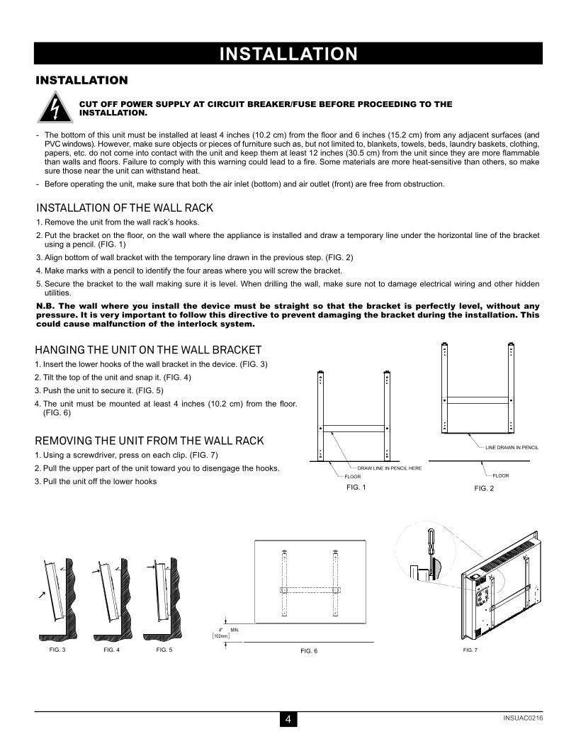
HANGiNG THE uNiT ON THE wALL bRACkET1. Insert the lower hooks of the wall bracket in the device. (FIG. 3)2. Tilt the top of the unit and snap it. (FIG. 4)3. Push the unit to secure it. (FIG. 5)4. The unit must be mounted at least 4 inches (10.2 cm) from the floor.
(FIG. 6)
REmOViNG THE uNiT FROm THE wALL RACk1. Using a screwdriver, press on each clip. (FIG. 7)2. Pull the upper part of the unit toward you to disengage the hooks.3. Pull the unit off the lower hooks
cut off poWeR supply at ciRcuit bReakeR/fuse befoRe pRoceeding to theinstallation.
- The bottom of this unit must be installed at least 4 inches (10.2 cm) from the floor and 6 inches (15.2 cm) from any adjacent surfaces (and PVC windows). However, make sure objects or pieces of furniture such as, but not limited to, blankets, towels, beds, laundry baskets, clothing, papers, etc. do not come into contact with the unit and keep them at least 12 inches (30.5 cm) from the unit since they are more flammable than walls and floors. Failure to comply with this warning could lead to a fire. Some materials are more heat-sensitive than others, so make sure those near the unit can withstand heat.
- Before operating the unit, make sure that both the air inlet (bottom) and air outlet (front) are free from obstruction.
iNSTALLATiON OF THE wALL RACk1. Remove the unit from the wall rack’s hooks.2. Put the bracket on the floor, on the wall where the appliance is installed and draw a temporary line under the horizontal line of the bracket
using a pencil. (FIG. 1)3. Align bottom of wall bracket with the temporary line drawn in the previous step. (FIG. 2)4. Make marks with a pencil to identify the four areas where you will screw the bracket.5. Secure the bracket to the wall making sure it is level. When drilling the wall, make sure not to damage electrical wiring and other hidden
utilities.n.b. the wall where you install the device must be straight so that the bracket is perfectly level, without any pressure. it is very important to follow this directive to prevent damaging the bracket during the installation. this could cause malfunction of the interlock system.
installation
FIG. 1 FIG. 2
LINE DRAWN IN PENCIL
DRAW LINE IN PENCIL HERE
FLOOR FLOOR
FIG. 1 FIG. 2
LINE DRAWN IN PENCIL
DRAW LINE IN PENCIL HERE
FLOOR FLOOR
#
##
4"102mm
MIN.FIG. 3 FIG. 4 FIG. 5
FIG. 6
FIG. 7
#
##
4"102mm
MIN.FIG. 3 FIG. 4 FIG. 5
FIG. 6
FIG. 7
#
##
4"102mm
MIN.FIG. 3 FIG. 4 FIG. 5
FIG. 6
FIG. 7

INSUAC02165
eleCtriCal ConneCtion & operation
with a BUilt-in eleCtroniC thermostathoW to set the tempeRatuReYou can change the temperature by increasing (top button) or decreasing (bottom button) the set point. The temperature set point will increase or decrease by increments of 0.5 °C (or 1 °F) each time you press down a button. If you hold down the button, the temperature will quickly scroll through, allowing a faster and more efficient setting. Once the temperature is set, release the button.
This unit was designed to be used with an electronic built-in or wall thermostat.
pRECiSE ELECTRONiC CONTROLA chrono-proportional electronic thermostat controls this unit with a high degree of accuracy in order to minimize temperature differences and increase your comfort level. It allows very stable temperature and ensures uniform comfort. It also keeps the casing at a low temperature, making it more secure.The chrono-proportional electronic thermostat entirely regulates the unit by increasing or decreasing the heating cycle percentage according to the selected temperature. Please note that the unit becomes warmer if the heating demand is higher and that it remains mildly warm when the demand is lower.n.b. if the unit is set on high or if it is not functioning at all, the temperature gage of the thermostat sensor cannot take a precise reading. however, the reading becomes extremely precise once the heating level has stabilized. therefore, uniform convection increases the precision of the thermostat.In order to obtain a precise and optimal ambient temperature reading, the unit must operate on a regular basis, i.e. without significant temperature variation for at least an hour. (This amount of time increases if a temperature change of more than 4 degrees is requested. Add approximately 15 minutes for every degree above 4).
electRonic Wall theRmostat contRolAn electronic wall thermostat equipped with a proportional tension variation that maintains a precise temperature is preferable thus increasing your comfort level.
opeRation
UnitElectric box
Connector (marette)
Green wire
L1
L2
this pRoduct must be connected by a qualified electRician, accoRding to the electRical and building codes effective in youR Region.
This unit must be connected by a certified electrician. Connect the bare wire (ground) to the green wire. Connect wires from the electric box to the unit’s supply leads.
electRical connection
standard models(à raCCordement fixe)
models with 120 V plUg (residential oUtlet)this unit is equipped With a thRee-WiRe gRounding type ac plug: - For safety reasons, the plug can only be inserted into an outlet with
grounding. If you are unable to insert the plug into the outlet, con-tact your electrician to have a suitable receptacle installed. Do not condemn the ground prong of the plug.
- this heater must be plugged into a dedicated 120 V circuit. the addition of other electrical appliances on this circuit may trip the circuit breaker.
- Plug the cord of the heater directly into the wall outlet (do not use an extension cord).
models with 120 V plUg (residential oUtlet)

INSUAC02166
operation, maintenanCe & troUbleshooting
tRoubleshooting
cut off power supply at circuit breaker/fuse and wait for the unit to cool down before cleaning. Use a soft rag for dusting. When cleaning, use only a damp rag and non-abrasive dish soap. Do not use abrasive or chemical cleaners because they may damage the finish. If the unit is used in a very dusty location, use a vacuum brush to remove dust and other foreign objects from the grilles. Note that cigarette smoke could yellow the discharge grill and that the best way to prevent it is to clean the unit on a regular basis. Do not remove the glass, clean only the air inlet and outlet.n.b. there is an electrical current linked to the unit even if the thermostat is set to off. this means that there is a risk of electric shock as long as the unit is energized.do not use cleaning products identified with these symbols:
maintenance
n.b. if you do not solve the problem after checking these points, cut off the power supply at the main electrical panel and contact our customer service (please refer to the limited WaRRanty to obtain the phone numbers).
pRoblem defective paRt oR paRt to check
The unit does not work• Open circuit breaker or fuse• Thermal protection activated• Faulty connections
The unit runs continuously • Defective thermostat or wrong thermostat setting
The enclosure is extremely hot • Defective thermal protection• Blocked air vents
The desired room temperature cannot be reached
• One or more defective elements• Defective thermostat or wrong thermosat setting• Voltage lower than indicated on the nameplate• Heat losses greater than the unit’s capacity
Overheating • Defective thermostat or wrong thermostat setting
The unit cycles under control of the thermal protection(overheat indicator) • Blocked air vents
The heater is on and the breaker trips • Faulty connections• Voltage higher than that indicated on the nameplate
ANTiFREEzE pROTECTiON In order to protect your home against freezing and limit energy consumption during long absences, put the thermostat on ANTIFREEZE mode. To enter this mode, lower the day temperature to between 3°C and 5°C. A Snowflake icon ( ) is displayed. This icon indicates that the economic and secure ANTIFREEZE mode is on.
THE OFF mOdETo turn the unit off, you must lower the temperature to less than 3°C. The inscription “- -” is displayed (note that there is still electrical current to the unit, meaning that there is a risk of electrical shock).
CELSiuS / FAHRENHEiT mOdETo switch the display from Celsius to Fahrenheit and vice versa, follow the steps listed here:1. Press and hold the two buttons at the same time.2. After 3 seconds, °C or °F will flash.3. Release the buttons to make the change. If the thermostat was in °C, it will now be in°F, and vice versa.

INSUAC02167
list of replaCement Components
Ref. # paRt # descRiption
1 V-UAC10W GLASS UAC 1000W
1 V-UAC15* GLASS UAC 1500W
1 V-UAC20W GLASS UAC 2000W
2 PROT-006 THERMAL PROTECTION 500W/1000W
2 PROT-005 THERMAL PROTECTION 1500W/2000W
3 EUC0250-05-1 ELEMENT 250W -120V
3 EUC0500-10-1 ELEMENT 500W -120V
3 EUC0750-15-1 ELEMENT 750W -120V
3 EUC0750-15-60 ELEMENT 750W -60V
3 EUC1000-20-1 ELEMENT 1000W -120V
4 (option) ST-214 ELECTRONIC THERMOSTAT
4 (option) ST-216 ELECTRONIC THERMOSTAT
- (option) CD-013 POWeR CORD 120 V/15 A
* Add W for white or BK for black
1 / 1X:\01_PRODUITS\FAMILLES\UAC\DOCUMENTATION\UAC_PIECES DE REMPLACEMENT
N.DEFFINS
2015-12-14 / adesmarais2015-05-14
3rd ANGLE PROJECTION3e ANGLE DE PROJECTION
UACXX01DESCRIPTION:
CRÉÉ PAR | CREATED BY:
CRÉÉ LE | CREATED ON:
# PIÈCE | PART #:
AFORMAT | SIZE:
FEUILLE | SHEET:XX.X° = ±0.5°
XX° = ±1°
.XXX = ±.015" [ ±.38mm]
CONSENT OF STELPRO DESIGN.
MIS À JOUR | UPDATED:
EMPLACEMENT:
TOLÉRANCES SI NON-SPÉCIFIÉES | TOLERANCES IF NOT SPECIFIED
LINÉAIRE | LINEAR: ANGULAIRE | ANGULAR:
.XX = ±.03" [ ±.76mm]
L'INFORMATION CONTENUE DANS CE DOCUMENT EST
LA PROPRIÉTÉ DE STELPRO DESIGN. EN AUCUN CAS,
L'INFORMATION NE PEUT ÊTRE UTILISÉE, SAUF SOUS
AUTORISATION ÉCRITE DE STELPRO DESIGN.
THE INFORMATION IN THIS DOCUMENT IS THE
PROPERTY OF STELPRO DESIGN. IN ANY CASE, THE
INFORMATION CAN'T BE USED, EXCEPT THE WRITTEN
MATÉRIEL | MATERIAL:
3
12
4
NO DESCRIPTION
4 THERMOSTAT ÉLECTRONIQUE3 ÉLÉMENT2 PROTECTION THERMIQUE1 DEVANT VITRE

INSUAC02168stelpro design inC. | saint-bruno-de-montarville | Quebec | J3V 6l7
This limited warranty is offered by Stelpro Design inc. (“Stelpro”) and applies to the following product made by Stelpro: UNIWATT UAC model. please read this limited warranty carefully. Subject to the terms of this warranty, Stelpro warrants its products and their components against defects in workmanship and/or materials for the following periods from the date of purchase: 2 years. This warranty applies only to the original purchaser; it is non-transferable and cannot be extended.claim pRoceduReIf at any time during the warranty period the unit becomes defective, you must cut off the power supply at the main electrical panel and contact 1) your installer or distributor, 2) your service center or 3) Stelpro’s customer service department. In all cases, you must have a copy of the invoice and provide the information written on the product nameplate. Stelpro reserves the right to examine or to ask one of its representatives to examine the product itself or any part of it before honoring the warranty. Stelpro reserves the right to replace the entire unit, refund its purchase price or repair a defective part. Please note that repairs made within the warranty period must be authorized in advance in writing by Stelpro and carried out by persons authorized by Stelpro.Before returning a product to Stelpro, you must have a Stelpro authorization number (RMA). To obtain it, call the customer service department at: 1-800-363-3414 (electricians and distributors - French), 1-800-343-1022 (electricians and distributors - English), or 1-866-766-6020 (consumers). The authorization number must be clearly written on the parcel or it will be refused.conditions, exclusions and disclaimeR of liabilityThis warranty is exclusive and in lieu of all other representations and warranties (except of title), expressed or implied, and Stelpro expressly disclaims and excludes any implied warranty of merchantability or implied warranty of fitness for a particular purpose.Stelpro’s liability with respect to products is limited as provided above. Stelpro shall not be subject to any other obligations or liabilities whatsoever, whether based on contract, tort or other theories of law, with respect to goods or services furnished by it, or any undertakings, acts or omissions relating thereto. Without limiting the generality of the foregoing, Stelpro expressly disclaims any liability for property or personal injury damages, penalties, special or punitive damages, damages for lost profits, loss of use of equipment, cost of capital, cost of substitute products, facilities or services, shutdowns, slowdowns, or for other types of economic loss or for claims of a dealer’s customers or any third party for such damages. Stelpro specifically disclaims all consequential, incidental and contingent damages whatsoever.This warranty does not cover any damages or failures resulting from: 1) a faulty installation or improper storage; 2) an abusive or abnormal use, lack of maintenance, improper maintenance (other than that prescribed by Stelpro) or a use other than that for which the unit was designed; 3) a natural disaster or an event out of Stelpro’s control, including, but not limited to, hurricanes, tornadoes, earthquakes, terrorist attacks, wars, overvoltage, flooding, water damages, etc. This warranty does not cover any accidental or intentional losses or damages, nor does it cover damages caused by negligence of the user or owner of the product. Moreover, it does not cover the cost of disconnection, transport, and installation.The warranty is limited to the repair or the replacement of the unit or the refund of its purchase price, at the discretion of stelpro. Any parts replaced or repaired within the warranty period with the written authorization of Stelpro will be warranted for the remainder of the original warranty period. This warranty will be considered null and void and Stelpro will have the right to refuse any claims if products have been altered without the written authorization of Stelpro and if the nameplate numbers have been removed or modified. This warranty does not cover scratches, dents, corrosion or discoloration caused by excessive heat, chemical cleaning products and abrasive agents. It does not cover any damage that occurred during the shipping. Some states and provinces do not allow the exclusion or limitation of incidental or consequential damages and some of them do not allow limitations on how long an implied warranty lasts, so these exclusions or limitations may not apply to you. This warranty gives you specific legal rights and you may have other rights which vary from state to state or from province to province.
limited warranty limited warranty limited warranty limited warranty limited warranty limited
limited warranty limited warranty limited warranty LimiTEd wARRANTy LimiTEd wARRANTylim
ite
d w
ar
ra
nt
y l
imit
ed
wa
rr
an
ty
lim
ite
d w
ar
ra
nt
y l
imit
edw
ar
ra
nt
y l
imit
ed
wa
rr
an
ty
lim
ite
d w
ar
ra
nt
y l
imit
ed
wa
rr
an
ty