Idaho National Laboratory
5
l ; · ( : f .•· · . . - - � ·- . . �.,-· - .. .. ---.,. - --··· . . ,. . : : .. Er!:RGEi:CY PROCEDURE EP- 2 ' . --· · _ ,·· / REV. U � DATE � . �. . . . .. '· .. · . . •
Transcript of Idaho National Laboratory
l;· ( : f
.•· · . . -
.. - � ·- ...
. �.,-.· - .. ..
.. ---.,.,J
- --··· . . .,
,.. .
: : .. Er!:RGEi:CY PROCEDURE EP- 22'
' '-
. --· ·
(__ ,··
/
REV. U �
DATE .5,k/7'i � . �. . . . .. '· ..
· . .
•

• • '
-EP-28 Rev. 0 5/5/79
EMERI1ENCY PROCEDURE EP-28 TMI UfiiT 2 COifTROL ROO� EVACUAT1011
1 .0 PURPOSE
1.1 Provide a procedure for maintaining the Unit in a safe and stable shutdown condition fn the unlikely event that all operating personnel are required to evacuate the Control Room. A stable shutdown condition is referenced here as:
A. Heat input from decay heat (alone or with the added heat load from Reactor Coolant Pump Operation) equals the heat removal from the Reactor Coolant System through rlatural Circulation.
B. Reactor Coolant.System inventory is being maintained relatively constant by makeup from the borated water storage tank to the makeup tank as required to compensate for any leakage.
C. Reactor Coolant System makeup and letdown fs being maintained by periodic makeup or letdown adjustments.
2.0 SnlPTONS
1. With steam bubble in pressurizer:
Due to the volume difference between Reactor Coolant System makeup (i.e., Reactor Coolant Pump Seal Supply) and letdown, there is a need to periodically either increase makeup or decrease letdown. Therefore, due to the location of local controls for the above two options, periodic control of letdown is selected. With flow in the letdown line, pressurizer level will slowly decrease with an attendant increase in makeup tank level. With letdown flow isolated, level changes will be the opposite.
2. \Hth pressurizer solid: (refer to Z-63)
Maintain pressure by balancing makeup flow with letdown flow. With seal injection flow secured, makeup flow is throttled to match letdown flow.
2.1 Conditions such as fire and/or smoke make continued occupancy of the Control Room impossible.
2.2 High radiation.
:.
:
. . .
-2- EP-28 Rev. 0 5/5/79
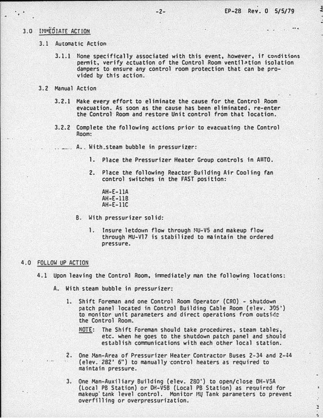
3.0 Ir:t�EOIATE ACTION
3.1 Automatic Action
3.1.1 tlone specifically associated with this event, however, ir conditions
permit, verify �ctuatfon of the Control Room ventfl�tion isolation dampers to ensure any control room protection that can be pro-vided by this action.
3.2 Manual Action
3.2.1 Make every effort to·eliminate the cause for the.Control Room evacuation. As soon as the cause has been eliminated, re-enter the Control Room and restore Unit control from that location.
3.2. 2 Complete the following actions prior to evacuating the Control Room:
A • . With_steam bubble in pressuriz�r:
1. Place the Pressurizer Heater Group controls in AIITO.
2. Place the following Reactor Building Air Cooling fan control switches in the FAST position:
AH-E-llA AH-E-llB AH-E-llC
B. Uith pressurizer solid:
4.0 FOLLOU UP ACTION
1. Insure letdo1�n flow through HU-V5 and makeup flow through MU-V17 is stabilized to maintain the ordered pressure.
4.1 Upon leaving the Control Room, immediately man the follo�in9 locations:
A. With steam bubble in pressurizer:
1. Shift Foreman and one Control Room Operator (CRO) - shutdown patch panel located in Control Building Cable Room (elev. 305') to monitor unit parameters and direct operations from outsirl: the Control Room. NOTE: The Shift Foreman should take procedures, steam tables,
etc. when he goes to the shutdown patch panel and should establish communications with each other local station.
2. One r-tan-Area of Pressurizer Heater Contractor Buses 2-34 and 2-44 (elev. 282' 6") to manually ·control heaters as required to maintain pressure.
3. One Man-Auxiliary Building (elev. 280') to open/close DH-V5A (Local PB Station) or DH-V5B (Local PB Station) as required for makeup' tank level control. Monitor HIJ Tank parameters to prevent overfilling or overpressurization.

.. . -3- EP-28 Rev. 0 5/5/79
4; 'one r�an-Aux't11iiry"Bufld1riq (elev. 280') to ooen/close HU-V376 (Local PB Station) as required for Pressurizer level control.
..•.
5. One·Han-Turbine Buildinq East Operatino Floor (elev. 331' 6") to control OTSG Startup.Feed Regulating Valves (FW-25A and FW-258) if necessary for mafntafnino level.
B. �ith nressurizer solid:
1. Shift Foreman and one control room operator (CRO} - Shutdown ·Patch Panel located in Control 8uild1n" Cable Qoom (elev. 305'}
to monitor unit �arameters and direct ooerations from outside -�he Control Room.
2. One Man and HP Tech-Area of low background radiation with caoabflitv of quick access to makeup control valve HU-V17. Isolate HU-V17 and adjust·makeup flow through bypass (MU-V1S5) as necessary to control RCS pressure.
3. One �!an-ftuxiliar.v Buildinq (elev. 280') to open/close OH-VSA (Local PB Station) or OH-VSB (Local PB Station) as required for makeu� tank level control.
4. One Han-Auxiliary Building (elev. 280') to open/close MU-V376 (Motor Control Center Bus 2-21EA) as required for rapfd RCS pressure control.
5. One Man-Turbine Building East Operatinq Floor (elev. 331' 6•) to control OTSr. Startup Feed Regulatino Valves (Fll-25A & FW-258) if necessary for maintaining level.
4.2 Cross tie the Nuclear and Turbine plant channels of the 'i & I pO\o�ered phone circuits in the Instrument Shop.
4.3 Maintain Pressurizer level as follows: A. With stea� huhhle in pressurizer:
Honitor Pressurizer level at the shutdown Patch Panel and control level between 150-200 inches by opening or closinq letdown line to Purification Oemineralizer Valve �-V376� If normal pressurizer level indication is not available, qo to Procedure l-107 for alternate level indication.
B. l!ith oressurizer solid:
¥.onitor P.CS pressure at Shutdown Patch Panel and control ordered QCS .Pressure bv adjusting I!U-Vl55 (!'U-Vl7 Byoass) with �-V17 isolated. If P.CS oressure drops raoidly, close MU-V376 to isolate letdown flow until RCS pressure is restored to ordered oressure.
4.4 l�onitor ttakeuo Tank level at the Shutdown Patch Panel and control level ··-··· . . . - . •. . .. between 55-80 inches by o!)eninq or closing Borated Hater Storaqe tank ..
to Oecay Heat Pump Valves OH-VSA or CH-V5B as required .to compensate for Reactor Coolant System leakage.
...

.. ' EP·28 Rev. 0 5/5/79 .:
.... . ., :,.� ·· . ·� 4.5 I('Reacio-r Coolant Puinit1s'in operation, monitor .. A" OTSG level at the·
shutdown Patch Panel and control level at approximately 95! on the Operate Range by manually positioning startup Feed Regulator Valve F'.4-V25A. If f n rla tura 1 Cf rcula t fon, continue opera t;ions in accordance with Procedure Z-39.
4.6 Mafntafn RCS pressure as follows:
A. With bubble fn pressurizer:
Monitor Reactor Coolant System pressure.at the Shutdown Patch Panel . �nd·controt pressure at the ordered pressure by manually cycling
Pressurizer Heaters at Pressurizer Heater Contactor Buses 2·34 and 2-44.
B. With solid pressurizer:
Monitor Reactor Coolant System pressure at the Shutdown Patch Panel and control l'lithin ordered pressure band by manually throttling HU-Vl55. Close HU·V376 if RCS pressure drops too rapidly.
:4-:1 HOni afr Reactor Coolant·System temperature at the Shutdown Patch Panel"·· ·
to ensure that reactor core-cooling is ��intained. If the Control Room evacuation is prolonged, monitor fncore thermocouples using millivolt potentiometers or brush recorders at the local panels.
4.8 While maintaining unit parameters stable, the CRO with the Shift Supervisor/Foreman should attempt to re-man the Control Room (if conditions permit and suitable re-entry precautions have been taken) and prove the ability to control the parameters in Steps 4.3 through 4.7. If �ossible, terminate this procedure and re-establish operation from the Control Room.
. . .
!