iCR Service Manualicrcompany.com/downloads/internal/service-manuals/1000-2600 cr_s… · CR Service...
75
CR Service Manual Computed Radiography System: iCR 1000, iCR 2600, iCR Vet, iCR Chiro Computed Radiography and X-ray Film Scanning System: iCR 1000 Dual, iCR 2600 Dual, iCR Vet Dual, iCR Chiro Dual Desktop Computed Radiography System: iCR 3600, iCR 1-D, iCR 3600 SF Version: 010 Updated: February 14, 2006 Language: English
Transcript of iCR Service Manualicrcompany.com/downloads/internal/service-manuals/1000-2600 cr_s… · CR Service...
CR Service Manual
Computed Radiography System: iCR 1000, iCR 2600, iCR Vet, iCR Chiro Computed Radiography and X-ray Film Scanning System: iCR 1000 Dual, iCR 2600 Dual, iCR Vet Dual, iCR Chiro Dual Desktop Computed Radiography System: iCR 3600, iCR 1-D, iCR 3600 SF Version: 010 Updated: February 14, 2006 Language: English
Page 2 of 75
iCRco 20406 Earl Street, Torrance CA 90503 Tel (310) 921-9559 Fax (310) 921-2559
FOREWORD Proprietary Notice and Disclaimer The information herein disclosed is the property of iCRco., Inc. Information in this document is subject to change without notice and does not represent a commitment by iCRco to incorporate changes or improvements in units previously sold or shipped. No part of this document may be reproduced or transmitted in any form, electronic or mechanical, including photocopying and recording, for any purpose other than the purchaser’s own use without the express written permission of iCRco. Copyright © 2003, 2004, 2005 All rights reserved. Trademarks COBRASCAN 312T, COBRASCAN 312L, COBRASCAN 312SE, COBRASCAN 612T, COBRASCAN 2000T, COBRASCAN 312SL , COBRASCAN 612SL , COBRASCAN 2000SL, COBRASCAN 2000M, iCR 1000SL, iCR 612SL, iCR 2000SL, iCR 1000, iCR 1000 Dual, iCR 2600, iCR 2600 Dual, iCR 3600, iCR 3600SF, iCR Vet, iCR Vet Dual, iCR Mobile, iCR 1-D, iCR Chiro, iCR Chiro Dual, www.icrcompany.com, www.cobrascan.com, and XPACS, QPC XSCAN32 are the trademarks of iCRco. All other trademarks are the property of their respective owners, and are hereby acknowledged. Terms Any one of the following iCR products will be referred to as the” iCR unit” throughout this document: iCR 1000, iCR 1000 Dual, iCR 2600, iCR 2600 Dual, iCR 2600SF, iCR 3600, iCR Vet, iCR Vet Dual, iCR Mobile, iCR 1-D, iCR Chiro, iCR Chiro Dual Any one of the following iCR products will be referred to as “iCR dual unit” throughout this document: iCR 1000 Dual, iCR 2600 Dual, iCR Vet Dual, iCR Chiro Dual Any one of the following iCR products will be referred to as “iCR desktop unit” throughout this document: iCR 3600, iCR 3600 SF, iCR 1-D Address: iCRco., Inc.
20406 Earl St. Torrance, CA, 90503
Telephone: 310.921.9559 FAX: 310.921.2559 Email: [email protected] Web: www.icrcompany.com
Page 3 of 75
iCRco 20406 Earl Street, Torrance CA 90503 Tel (310) 921-9559 Fax (310) 921-2559
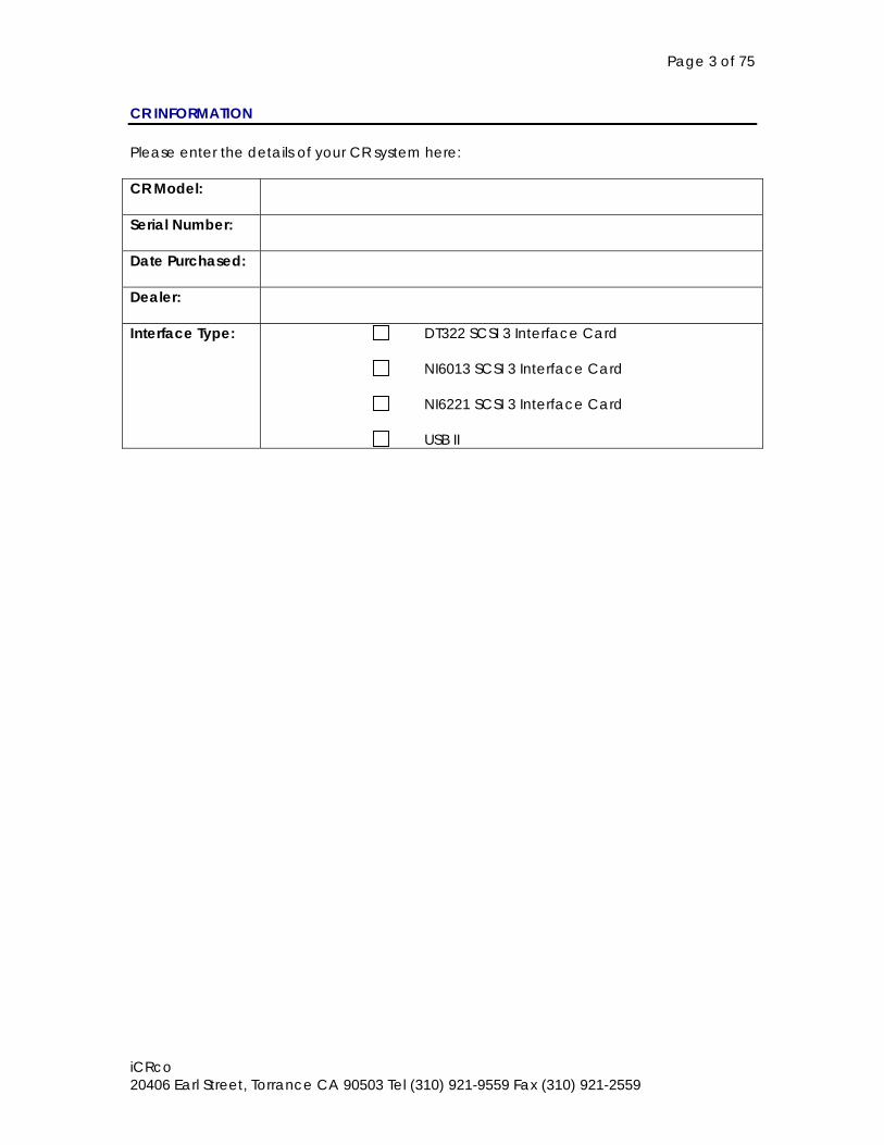
CR INFORMATION Please enter the details of your CR system here: CR Model:
Serial Number:
Date Purchased:
Dealer:
Interface Type: DT322 SCSI 3 Interface Card
NI6013 SCSI 3 Interface Card
NI6221 SCSI 3 Interface Card
USB II
Page 4 of 75
iCRco 20406 Earl Street, Torrance CA 90503 Tel (310) 921-9559 Fax (310) 921-2559
TABLE OF CONTENTS 1.0 INTRODUCTION ............................................................................................................... 8
1.1 Overview .................................................................................................................8 1.2 Reference Documents ..........................................................................................8 1.3 Safety Information..................................................................................................9
1.3.1 Conventions ..............................................................................................9 1.3.2 Laser Safety .............................................................................................10 1.3.3 Electrical Hazards ...................................................................................10
1.4 FCC Notification ...................................................................................................10 1.5 One Year Limited Hardware Warranty .............................................................11
2.0 PRE-INSTALLATION ........................................................................................................ 12 2.1 Pre-Installation of iCR 1000, iCR 2600, iCR Vet, iCR Chiro ..............................12
2.1.1 Voltage Requirements...........................................................................12 2.1.2 Environmental .........................................................................................12 2.1.3 Systems Specifications ...........................................................................13 2.1.4 Physical requirements ............................................................................13 2.1.5 Connectivity and power supply...........................................................13
2.2 Pre-Installation of iCR 1000 Dual, iCR 2600 Dual, iCR Vet Dual, iCR Chiro Dual 14
2.2.1 Voltage Requirements...........................................................................14 2.2.2 Environmental .........................................................................................14 2.2.3 Systems Specifications ...........................................................................14 2.2.4 Physical requirements ............................................................................14 2.2.5 Connectivity and power supply...........................................................14
2.3 Pre-Installation of iCR 3600 SF, iCR 3600, iCR 1-D.............................................15 2.3.1 Voltage Requirements...........................................................................15 2.3.2 Environmental .........................................................................................15 2.3.3 Systems Specifications ..........................................................................15 2.3.4 Physical requirements ............................................................................15 2.3.5 Connectivity and power supply...........................................................15
3.0 DRIVER INSTALLATION................................................................................................... 16 3.1 Installing DT322 board drivers .............................................................................16 3.2 Installing NI6013 or NI6221 board drivers ..........................................................17 3.3 Installing USB drivers .............................................................................................17 3.4 Installing iCRco Film Scanner Drivers for iCR 1000 Dual, iCR 2600 Dual, iCR Vet Dual, iCR Chiro............................................................................................................18
4.0 SOFTWARE INSTALLATION............................................................................................. 19 4.1 Installing QPC XSCAN32 ......................................................................................19 4.2 Installing the Applied Motion Products SCL Setup Utility................................20
5.0 HARDWARE INSTALLATION ........................................................................................... 21 5.1 Hardware Installation for iCR 1000, iCR 2600, iCR Vet, iCR Chiro (2005 Model) 21
5.1.1 PC Specifications for iCR 1000, iCR 2600, iCR Vet, iCR Chiro (2005 Model)....................................................................................................................21 5.1.2 USBII or DAC Installation for iCR 1000, iCR 2600, iCR Vet, iCR Chiro (2005 Model) .........................................................................................................21 5.1.3 Tools Required for iCR 1000, iCR 2600, iCR Vet, iCR Chiro (2005 Model)....................................................................................................................21 5.1.4 Uncrating iCR 1000, iCR 2600, iCR Vet, iCR Chiro (2005 Model) .....22 5.1.5 Setting up and Installing - iCR 1000, iCR 2600, iCR Vet, iCR Chiro (2005 Model) .........................................................................................................23
Page 5 of 75
iCRco 20406 Earl Street, Torrance CA 90503 Tel (310) 921-9559 Fax (310) 921-2559
5.1.6 Power Switch Locations for iCR 1000, iCR 2600, iCR Vet, iCR Chiro (2005 Model) .........................................................................................................25 5.1.7 Power and Scan lights for iCR 1000, iCR 2600, iCR Vet, iCR Chiro (2005 Model) .........................................................................................................25 5.1.8 Installing Power Cable for iCR 1000, iCR 2600, iCR Vet, iCR Chiro (2005 Model) .........................................................................................................25 5.1.9 International Power Cable for iCR 1000, iCR 2600, iCR Vet, iCR Chiro (2005 Model) ..............................................................................................26
5.2 Hardware Installation for iCR 1000 Dual, iCR 2600 Dual, iCR Vet Dual (2005 Model) 26
5.2.1 PC Specifications for iCR 1000 Dual, iCR 2600 Dual, iCR Vet Dual (2005 Model) .........................................................................................................26 5.2.2 USBII or DAC Installation for iCR 1000 Dual, iCR 2600 Dual, iCR Vet Dual (2005 Model)................................................................................................26 5.2.3 Tools Required for iCR 1000 Dual, iCR 2600 Dual, iCR Vet Dual (2005 Model)....................................................................................................................26 5.2.4 Uncrating the iCR 1000 Dual, iCR 2600 Dual, iCR Vet Dual (2005 Model)....................................................................................................................26 5.2.5 Setting up and Installing - iCR 1000 Dual, iCR 2600 Dual, iCR Vet Dual (2005 Model)................................................................................................26 5.2.6 Power Switch Locations for iCR 1000 Dual, iCR 2600 Dual, iCR Vet Dual (2005 Model)................................................................................................28 5.2.7 Power and Scan lights - iCR 1000 Dual, iCR 2600 Dual, iCR Vet Dual (2005 Model) .........................................................................................................28 5.2.8 Installing Power Cable - iCR 1000 Dual, iCR 2600 Dual, iCR Vet Dual (2005 Model) .........................................................................................................28 5.2.9 International Power Cable - iCR 1000 Dual, iCR 2600 Dual, iCR Vet Dual (2005 Model)................................................................................................28
5.3 Hardware Installation for iCR 3600 SF, iCR 1-D (2005 Model) ........................29 5.3.1 PC Specifications for iCR 3600 SF, iCR 1-D (2005 Model) .................29 5.3.2 Uncrating the iCR 3600 SF, iCR 1-D (2005 Model)..............................29 5.3.5 Setting up and Installing - iCR 3600 SF, iCR 1-D (2005 Model) .........29
5.4 Hardware Installation for iCR 1000, iCR 2600, iCR Vet (2004 model) ...........30 5.4.1 Setting up and Installing - iCR 1000, iCR 2600, iCR Vet (2004 model) 30 5.4.2 Power Switch Locations for iCR 1000, iCR 2600, iCR Vet (2004 model)....................................................................................................................32
5.5 Wall Mounting Plates ...........................................................................................33 5.6 Installation of DAC cable from iCR unit to PC .................................................33 5.7 Installing of COM1 cable from iCR unit to PC..................................................34 5.8 Installing of USB cable from iCR unit to PC.......................................................34 6.1 System Operation of iCR 1000, iCR 2600, iCR Vet, iCR Chiro (2005 Model)35
6.1.1 Power-Up .................................................................................................35 6.1.2 Technique ................................................................................................35 6.1.3 Cassette Handling and Loading..........................................................37 6.1.4 Scanning a cassette ..............................................................................40 6.1.5 Viewing and Processing images ..........................................................41
6.2 System Operation of iCR 1000 Dual, iCR 2600 Dual, iCR Vet Dual (2005 Model) 42
6.2.1 Power-Up .................................................................................................42 6.1.2 Technique ................................................................................................42 6.2.3 Cassette Handling and Loading..........................................................42
Page 6 of 75
iCRco 20406 Earl Street, Torrance CA 90503 Tel (310) 921-9559 Fax (310) 921-2559
6.2.4 Scanning a cassette ..............................................................................42 6.2.5 Viewing and Processing images ..........................................................43
6.3 System Operation of iCR 1000, iCR 2600, iCR Vet (2004 Model)...................43 6.3.1 Power-Up .................................................................................................43 6.3.2 Technique ................................................................................................43 6.3.3 Cassette Handling and Loading..........................................................43 6.3.4 Scanning a cassette ..............................................................................44 6.3.5 Viewing and Processing images ..........................................................44
6.4 Quick Start Guides ...............................................................................................44 7.0 THEORY OF OPERATION................................................................................................ 45
7.1 Product Overview ................................................................................................45 7.2 System Configuration ..........................................................................................46
7.2.1 Optical Beam Path.................................................................................46 7.2.2 Optical Beam Path.................................................................................47 7.3.1 Data Acquisition Board .........................................................................48 7.3.2 PMT PreAmp Board ................................................................................48 7.3.3 Galvanometer Board.............................................................................48 7.3.4 Indicator Board .......................................................................................48 7.3.5 Indicator/FF Interface Board ...............................................................48 7.3.6 Reference LED Board............................................................................49 7.3.8 Power Distribution ..................................................................................49
7.4 Sub-System Operation.........................................................................................50 7.4.1 ADC Board..............................................................................................50 7.4.2 Calibration...............................................................................................50 7.4.3 PMT Amplifier ..........................................................................................50
8.0 SERVICE ADJUSTMENTS................................................................................................. 51 8.1 Optics .....................................................................................................................51 8.2 PMT Sub System ....................................................................................................51
9.0 PERIODIC MAINTENANCE ........................................................................................... 52 9.1 Periodic Cleaning ................................................................................................52 9.2 Cleaning optical mirrors .......................................................................................53 9.3 Cleaning optical mirrors on iCR3600SF and iCR1-D .........................................53
10.0 DIAGNOSTICS .............................................................................................................. 54 10.1 Troubleshooting ....................................................................................................54 10.2 Symptoms and Their Causes...............................................................................54
10.2.1 Vertical Lines In Images iCR Unit – iCR 1000, iCR 2600, iCR Vet, iCR Chiro, iCR 1000 Dual, iCR 2600 Dual, iCR Vet Dual, iCR Chiro Dual (2005 model) 55 10.2.2 Vertical Lines In Images iCR Unit – iCR 3600 SF, iCR 1-D ...............60 10.2.3 Horizontal Lines and Banding In Images..........................................63 10.2.4 System Will Not Detect Phosphor Screens .......................................67 10.2.5 No Galvanometer Movement ..........................................................67 10.2.6 Initializing the CR motor controller for the first time.........................68 10.2.7 Slide adjustment procedure ...............................................................69
10.3 Diagnostic Programs............................................................................................71 11.0 REPLACEMENT PARTS ................................................................................................... 72
11.1 Removing the iCR Back Cover ..........................................................................72 11.1.1 Main Enclosure Removal ....................................................................72 11.1.2 Front Cover Removal ..........................................................................72
11.2 Field Modules ........................................................................................................72 11.3 Optics Module ......................................................................................................72
11.3.1 PMT Sub-System ....................................................................................73
Page 7 of 75
iCRco 20406 Earl Street, Torrance CA 90503 Tel (310) 921-9559 Fax (310) 921-2559
11.3.2 Laser Diode Driver Assembly Removal and Replacement............73 11.4 Removing Laser Diode Module..........................................................................73 11.5 Focusing the Laser................................................................................................73 11.6 Galvanometer Removal .....................................................................................73 11.7 Drive Motor Assembly ..........................................................................................74
12.0 SCHEMATICS AND DRAWINGS ......................................................................................... 75
Page 8 of 75
iCRco 20406 Earl Street, Torrance CA 90503 Tel (310) 921-9559 Fax (310) 921-2559
1.0 INTRODUCTION 1.1 Overview The iCR unit is an ultra high resolution Computed Radiography device. It is designed to scan phosphor screens (CR plates) using patented technology. CR plates are held by a clip and transported past a scanning head without bending or using rollers. This Flat Scan Path results in ultra high resolution images with high fidelity across the entire image. High resolution is achieved from the CR plates by coupling the flat scan path with a high energy (35mW) red laser focused down to a 50 micron flying spot by a lens system. The flying spot is created using a galvanometer scanner. The precision rack and pinion drive system moves the rigid CR plate over the scan head, the laser spot excites the plate, releasing light energy into a light collection cavity. Two Photomultiplier sensors capture the light and an A/D board converts the analog signal into a 16 bit digital image. Ultra High resolution film scanning is achieved in the iCR dual unit by using a 14000 element CCD line camera coupled to the precision rack and pinion drive system. The film is driven past the scan head and a very bright solid state light source illuminates the film as it passes over the scan head. Light is collected by the CCD camera and converted to a 16 bit image through the A/D board. Once the 16 bit data is collected it is converted to a DICOM 3.0 image and can be stored, viewed, manipulated, and sent to any other storage device, printer, or viewing station through DICOM. This document contains a basic technical overview of the iCR unit including the optical systems, electronic components, and driving software subsystems. A general description of the systems functionality and user interfaces will be described. Unpacking of the hardware is covered and software installation, service adjustments and troubleshooting are also included. This document is intended for users or service people who need to understand the basic underlying principles of operation for the iCR unit. 1.2 Reference Documents * QPC XSCAN32 Manual and Help Documentation * iCR Quickstart Manual
Page 9 of 75
iCRco 20406 Earl Street, Torrance CA 90503 Tel (310) 921-9559 Fax (310) 921-2559
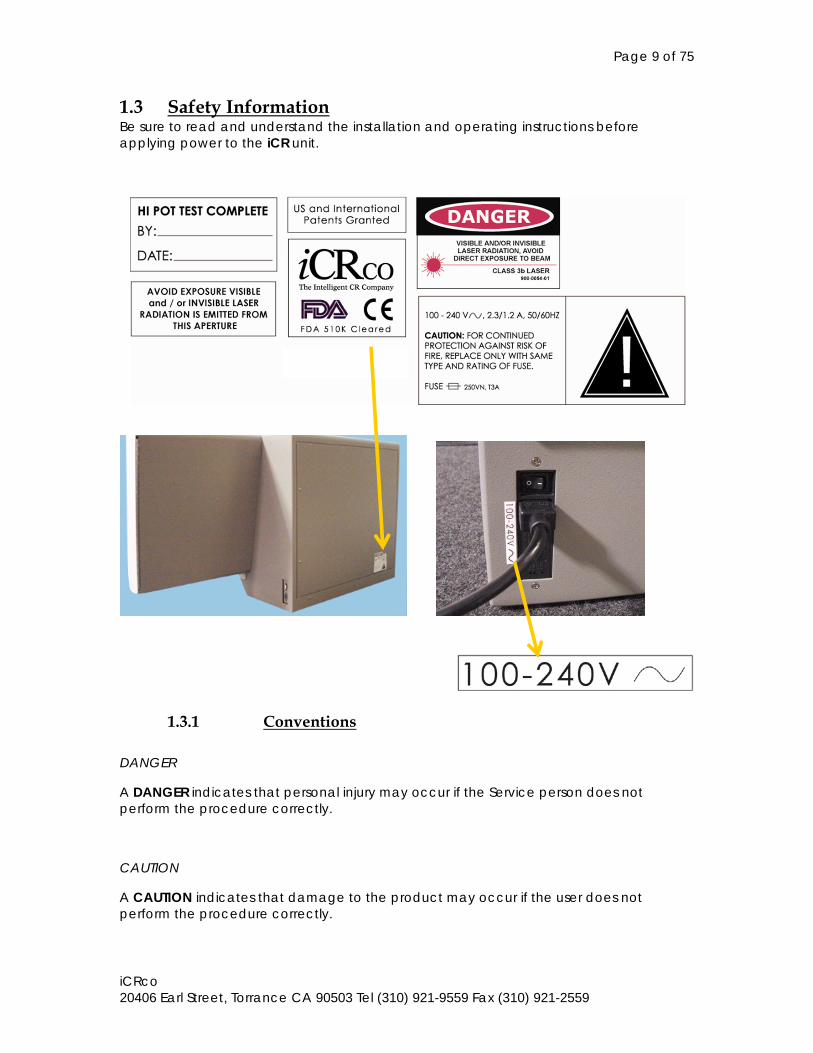
1.3 Safety Information Be sure to read and understand the installation and operating instructions before applying power to the iCR unit.
1.3.1 Conventions
DANGER
A DANGER indicates that personal injury may occur if the Service person does not perform the procedure correctly.
CAUTION
A CAUTION indicates that damage to the product may occur if the user does not perform the procedure correctly.
Page 10 of 75
iCRco 20406 Earl Street, Torrance CA 90503 Tel (310) 921-9559 Fax (310) 921-2559
PRECAUTION
A PRECAUTION indicates that inconvenience to the user, such as loss of data, may occur if the user does not perform the procedure correctly.
NOTE
A NOTE indicates the information that should be called to the attention of the user.
WARNING
A WARNING indicates that a user must be constantly aware of something that may prove hazardous.
1.3.2 Laser Safety
The iCR unit incorporates a Red >30mw high-power solid-state laser diode. The iCR covers protect the service person from direct exposure to laser light. These covers will protect a user/service person only if they are properly installed. Covers must be removed and replaced by properly trained service personnel. Contact iCRco if there are any issues with the covers being damaged and replace them. DANGER THIS EQUIPMENT EMPLOYS A LASER. LASER RADIATION MAY BE PRESENT IF THE COBRASCAN iCR IS OPERATED WITHOUT COVERS. AVOID LASER BEAM. DIRECT EYE EXPOSURE TO LASER LIGHT MUST BE AVOIDED.
1.3.3 Electrical Hazards WARNING THIS EQUIPMENT IS OPERATED WITH HAZARDOUS VOLTAGES WHICH CAN SHOCK, BURN OR CAUSE DEATH. The equipment must be serviced by properly trained technicians certified by iCRco, Inc. Do not connect the iCR unit with a damaged or sub-standard power cable. Do not use an extension cord with this device. The iCR unit should be properly grounded and power connections inspected to ensure safe operation. Use at least a 670VA uninterruptible power supply (UPS) with this device, as it is sensitive to variations in power. 1.4 FCC Notification This equipment generates, uses, and can radiate radio frequency energy, and if not installed properly, can cause interference with radio communications.
Page 11 of 75
iCRco 20406 Earl Street, Torrance CA 90503 Tel (310) 921-9559 Fax (310) 921-2559
1.5 One Year Limited Hardware Warranty iCRco warrants its hardware product against defects in materials and workmanship for the period of ONE (1) YEAR from the date of original shipment. Should any defect(s) be discovered, the product may be returned to an authorized iCRco dealer or to iCRco. iCRco shall, at its sole discretion, repair or replace the product upon return during the warranty period. (Note: should the product be outside of the USA and returned to the USA for repair, iCRco is not responsible for costs incurred due to: Shipping, customs, duties, et al.) This warranty does not apply if the product has been damaged by accident, or through misuse or abuse. If the product has been opened or altered without written authorization by iCRco, the warranty will not be applicable. If warranty repair is determined to be necessary by iCRco, the customer shall pay for shipping to iCRco’s factory and iCRco will pay for return shipping of the repaired unit to the customer. The hardware must be returned to iCRco in its original packaging. If the hardware is damaged from incorrect packaging the current warranty repair is void and the customer is liable for all the parts and labor costs of the repairs. Original packaging can be purchased from iCRco (please call 310-921-9559). No returns will be accepted without an RMA number issued by iCRco (please call 310-921-9559). Any returns to iCRco without an iCRco issued RMA number will be automatically returned to sender. This warranty applies only to hardware products manufactured by, or for, iCRco, that can be identified by the “iCRco” brand name, trade name, or logo affixed to the product. iCRco does not warrant any products that are not iCRco branded products. THE WARRANTY AND REMEDIES SET FORTH ABOVE, ARE EXCLUSIVE, AND IN LIEU OF ALL OTHERS, WHETHER IT IS ORAL, WRITTEN, EXPRESSED OR IMPLIED. iCRco SPECIFICALLY DISCLAIMS ANY, AND ALL, IMPLIED WARRANTIES OF MERCHANTABILITY AND FITNESS FOR A PARTICULAR PURPOSE. iCRco IS NOT RESPONSIBLE FOR SPECIAL, INCIDENTAL OR CONSEQUENTIAL DAMAGES RESULTING FROM ANY BREACH OF WARRANTY. iCRco IS NOT RESPONSIBLE UNDER ANY OTHER LEGAL THEORY, INCLUDING, BUT NOT LIMITED TO, LOSS OF PROFITS, AND ANY COSTS OF RECOVERING, REPROGRAMMING OR REPRODUCING ANY PROGRAM OR DATA STORED OR USED WITH iCRco PRODUCTS.
Page 12 of 75
iCRco 20406 Earl Street, Torrance CA 90503 Tel (310) 921-9559 Fax (310) 921-2559
2.0 PRE-INSTALLATION 2.1 Pre-Installation of iCR 1000, iCR 2600, iCR Vet, iCR Chiro
2.1.1 Voltage Requirements The iCR unit incorporates an international switching power supply. iCRco employs CE certified medical grade universal power supplies to allow the unit to work between 90 to 253V AC 50/60 HZ. In order to run the unit with different power types, apply voltage to the power input module at the end of the iCR unit. For international units, a local power cord must be used that can handle the power requirements of the unit. A computer grade power cord is sufficient. NOTE: The power input module will be set to the proper voltage setting at the factory. If a voltage change is necessary, remove the voltage plate on the power entry module and select the proper voltage setting.
2.1.2 Environmental There are several environmental factors to consider when installing the iCR unit. The ambient light in which the iCR unit operates is important. The iCR units are daylight CR digitizers. This means that they can be deployed in a fully lit room. The daylight characteristics of the device are only evident when the protective cover is in place. If the iCR unit is placed in a dark or semi-dark room, it may be possible to scan without closing the protective cover. If the iCR unit is allowed to scan without the protective cover in place this may introduce image artifacts. The iCR digitizer should not be placed in a darkroom with a film processor present. This will void the warranty. The humidity and temperature limits are 20 to 80% non-condensing, and 15°C to 35°C, operating, respectively. The room should have good ventilation. Another factor to consider prior to installing the iCR unit is dust and particulates in the environment. The iCR unit is designed to be resistant to dust and particulates that may be present at the installation site. This is accomplished by 3 systems that work together to ensure that the unit remains clean. 1. The cooling fan sucks air into the device. There is a filter in front of the fan to
ensure that the air in the iCR is clean. 2. The cooling fan ensures that the pressure in the case is slightly higher than the
outside pressure. Thus dust and dirt do not enter the device through the scan head.
3. All the optics are sealed in the optic cavity, separate from the electronics. Although these systems are in place, in a dusty environment, small amounts of dust and/or dirt may enter the optic cavity. This dust could affect image quality. To prevent this potential issue, it is recommended that the unit be installed and operated in a clean, dry environment.
NOTE: The 3600SF unit does not have a cooling fan. Optics are sealed, and the only
cooling is convection from the CR case.
Page 13 of 75
iCRco 20406 Earl Street, Torrance CA 90503 Tel (310) 921-9559 Fax (310) 921-2559
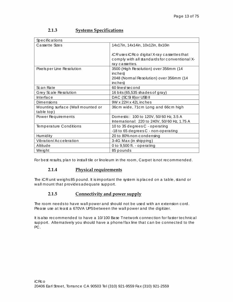
2.1.3 Systems Specifications Specifications Cassette Sizes 14x17in, 14x14in, 10x12in, 8x10in
iCR uses iCRco digital X-ray cassettes that comply with all standards for conventional X-ray cassettes.
Pixels per Line Resolution 3500 (High Resolution) over 356mm (14 inches) 2048 (Normal Resolution) over 356mm (14 inches)
Scan Rate 60 lines/second Grey Scale Resolution 16 bits (65,535 shades of gray) Interface DAC (SCSI III)or USB II Dimensions 9W x 22H x 42L inches Mounting surface (Wall mounted or table top)
36cm wide, 71cm Long and 66cm high
Power Requirements Domestic: 100 to 120V, 50/60 Hz, 3.5 A International: 220 to 240V, 50/60 Hz, 1.75 A
Temperature Conditions 10 to 35 degrees C - operating -18 to 65 degrees C - non-operating
Humidity 20 to 80% non-condensing Vibration/Acceleration 3-4G Max (in shipping) Altitude 0 to 9,500 ft. - operating Weight 85 pounds
For best results, plan to install tile or linoleum in the room, Carpet is not recommended.
2.1.4 Physical requirements The iCR unit weighs 85 pound. It is important the system is placed on a table, stand or wall mount that provides adequate support.
2.1.5 Connectivity and power supply The room needs to have wall power and should not be used with an extension cord. Please use at least a 670VA UPS between the wall power and the digitizer. It is also recommended to have a 10/100 Base T network connection for faster technical support. Alternatively you should have a phone/fax line that can be connected to the PC.
Page 14 of 75
iCRco 20406 Earl Street, Torrance CA 90503 Tel (310) 921-9559 Fax (310) 921-2559
2.2 Pre-Installation of iCR 1000 Dual, iCR 2600 Dual, iCR Vet Dual, iCR Chiro Dual
2.2.1 Voltage Requirements Refer to section 2.1.1.
2.2.2 Environmental Refer to section 2.1.2
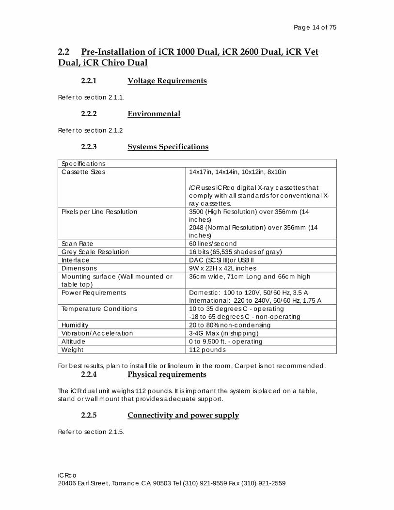
2.2.3 Systems Specifications Specifications Cassette Sizes 14x17in, 14x14in, 10x12in, 8x10in
iCR uses iCRco digital X-ray cassettes that comply with all standards for conventional X-ray cassettes.
Pixels per Line Resolution 3500 (High Resolution) over 356mm (14 inches) 2048 (Normal Resolution) over 356mm (14 inches)
Scan Rate 60 lines/second Grey Scale Resolution 16 bits (65,535 shades of gray) Interface DAC (SCSI III)or USB II Dimensions 9W x 22H x 42L inches Mounting surface (Wall mounted or table top)
36cm wide, 71cm Long and 66cm high
Power Requirements Domestic: 100 to 120V, 50/60 Hz, 3.5 A International: 220 to 240V, 50/60 Hz, 1.75 A
Temperature Conditions 10 to 35 degrees C - operating -18 to 65 degrees C - non-operating
Humidity 20 to 80% non-condensing Vibration/Acceleration 3-4G Max (in shipping) Altitude 0 to 9,500 ft. - operating Weight 112 pounds
For best results, plan to install tile or linoleum in the room, Carpet is not recommended.
2.2.4 Physical requirements The iCR dual unit weighs 112 pounds. It is important the system is placed on a table, stand or wall mount that provides adequate support.
2.2.5 Connectivity and power supply Refer to section 2.1.5.
Page 15 of 75
iCRco 20406 Earl Street, Torrance CA 90503 Tel (310) 921-9559 Fax (310) 921-2559
2.3 Pre-Installation of iCR 3600 SF, iCR 3600, iCR 1-D
2.3.1 Voltage Requirements Refer to section 2.1.1.
2.3.2 Environmental Refer to section 2.1.2
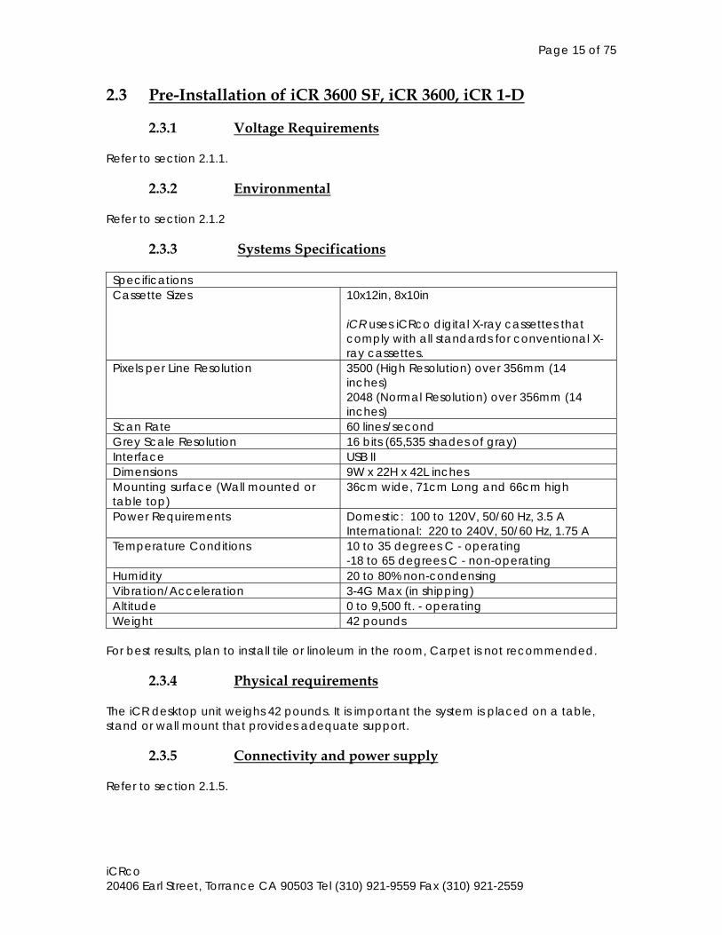
2.3.3 Systems Specifications Specifications Cassette Sizes 10x12in, 8x10in
iCR uses iCRco digital X-ray cassettes that comply with all standards for conventional X-ray cassettes.
Pixels per Line Resolution 3500 (High Resolution) over 356mm (14 inches) 2048 (Normal Resolution) over 356mm (14 inches)
Scan Rate 60 lines/second Grey Scale Resolution 16 bits (65,535 shades of gray) Interface USB II Dimensions 9W x 22H x 42L inches Mounting surface (Wall mounted or table top)
36cm wide, 71cm Long and 66cm high
Power Requirements Domestic: 100 to 120V, 50/60 Hz, 3.5 A International: 220 to 240V, 50/60 Hz, 1.75 A
Temperature Conditions 10 to 35 degrees C - operating -18 to 65 degrees C - non-operating
Humidity 20 to 80% non-condensing Vibration/Acceleration 3-4G Max (in shipping) Altitude 0 to 9,500 ft. - operating Weight 42 pounds
For best results, plan to install tile or linoleum in the room, Carpet is not recommended.
2.3.4 Physical requirements The iCR desktop unit weighs 42 pounds. It is important the system is placed on a table, stand or wall mount that provides adequate support.
2.3.5 Connectivity and power supply Refer to section 2.1.5.
Page 16 of 75
iCRco 20406 Earl Street, Torrance CA 90503 Tel (310) 921-9559 Fax (310) 921-2559
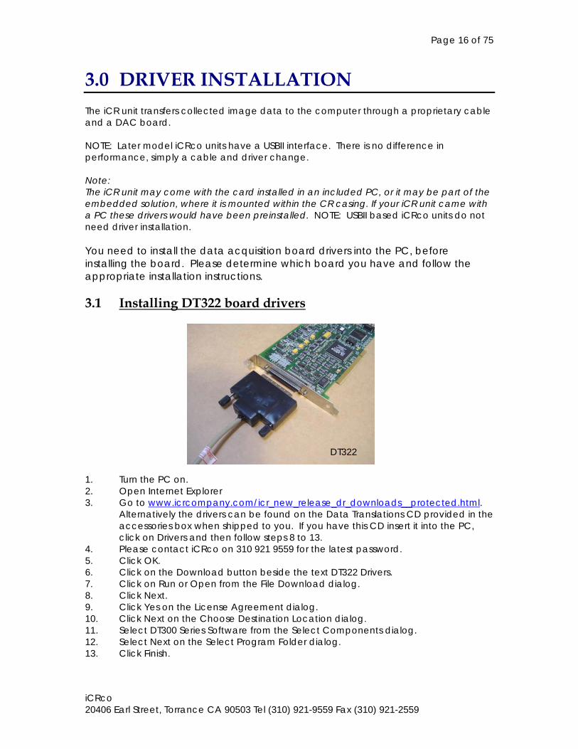
3.0 DRIVER INSTALLATION The iCR unit transfers collected image data to the computer through a proprietary cable and a DAC board. NOTE: Later model iCRco units have a USBII interface. There is no difference in performance, simply a cable and driver change. Note: The iCR unit may come with the card installed in an included PC, or it may be part of the embedded solution, where it is mounted within the CR casing. If your iCR unit came with a PC these drivers would have been preinstalled. NOTE: USBII based iCRco units do not need driver installation. You need to install the data acquisition board drivers into the PC, before installing the board. Please determine which board you have and follow the appropriate installation instructions. 3.1 Installing DT322 board drivers 1. Turn the PC on. 2. Open Internet Explorer 3. Go to www.icrcompany.com/icr_new_release_dr_downloads__protected.html.
Alternatively the drivers can be found on the Data Translations CD provided in the accessories box when shipped to you. If you have this CD insert it into the PC, click on Drivers and then follow steps 8 to 13.
4. Please contact iCRco on 310 921 9559 for the latest password. 5. Click OK. 6. Click on the Download button beside the text DT322 Drivers. 7. Click on Run or Open from the File Download dialog. 8. Click Next. 9. Click Yes on the License Agreement dialog. 10. Click Next on the Choose Destination Location dialog. 11. Select DT300 Series Software from the Select Components dialog. 12. Select Next on the Select Program Folder dialog. 13. Click Finish.
DT322
Page 17 of 75
iCRco 20406 Earl Street, Torrance CA 90503 Tel (310) 921-9559 Fax (310) 921-2559
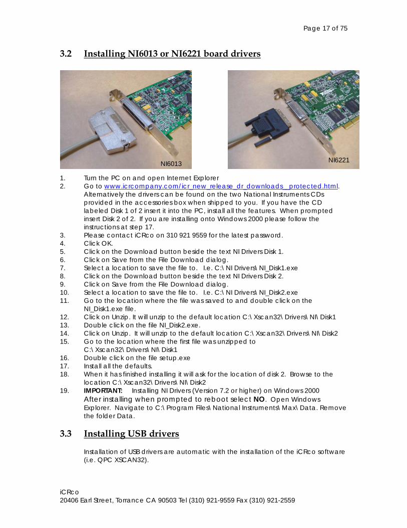
3.2 Installing NI6013 or NI6221 board drivers 1. Turn the PC on and open Internet Explorer 2. Go to www.icrcompany.com/icr_new_release_dr_downloads__protected.html.
Alternatively the drivers can be found on the two National Instruments CDs provided in the accessories box when shipped to you. If you have the CD labeled Disk 1 of 2 insert it into the PC, install all the features. When prompted insert Disk 2 of 2. If you are installing onto Windows 2000 please follow the instructions at step 17.
3. Please contact iCRco on 310 921 9559 for the latest password. 4. Click OK. 5. Click on the Download button beside the text NI Drivers Disk 1. 6. Click on Save from the File Download dialog. 7. Select a location to save the file to. I.e. C:\NI Drivers\NI_Disk1.exe 8. Click on the Download button beside the text NI Drivers Disk 2. 9. Click on Save from the File Download dialog. 10. Select a location to save the file to. I.e. C:\NI Drivers\NI_Disk2.exe 11. Go to the location where the file was saved to and double click on the
NI_Disk1.exe file. 12. Click on Unzip. It will unzip to the default location C:\Xscan32\Drivers\NI\Disk1 13. Double click on the file NI_Disk2.exe. 14. Click on Unzip. It will unzip to the default location C:\Xscan32\Drivers\NI\Disk2 15. Go to the location where the first file was unzipped to
C:\Xscan32\Drivers\NI\Disk1 16. Double click on the file setup.exe 17. Install all the defaults. 18. When it has finished installing it will ask for the location of disk 2. Browse to the
location C:\Xscan32\Drivers\NI\Disk2 19. IMPORTANT: Installing NI Drivers (Version 7.2 or higher) on Windows 2000
After installing when prompted to reboot select NO. Open Windows Explorer. Navigate to C:\Program Files\National Instruments\Max\Data. Remove the folder Data.
3.3 Installing USB drivers
Installation of USB drivers are automatic with the installation of the iCRco software (i.e. QPC XSCAN32).
NI6013 NI6221
Page 18 of 75
iCRco 20406 Earl Street, Torrance CA 90503 Tel (310) 921-9559 Fax (310) 921-2559
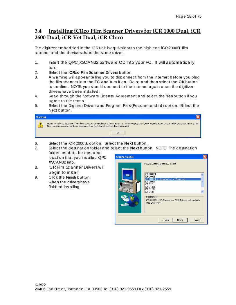
3.4 Installing iCRco Film Scanner Drivers for iCR 1000 Dual, iCR 2600 Dual, iCR Vet Dual, iCR Chiro The digitizer embedded in the iCR unit is equivalent to the high end iCR 2000SL film scanner and the devices share the same driver. 1. Insert the QPC XSCAN32 Software CD into your PC. It will automatically
run. 2. Select the iCRco Film Scanner Drivers button. 3. A warning will appear telling you to disconnect from the Internet before you plug
the film scanner into the PC and turn it on. Do so and then select the OK button to confirm. NOTE: you should connect to the Internet again once the digitizer drivers have been installed.
4. Read through the Software License Agreement and select the Yes button if you agree to the terms.
5. Select the Digitizer Drivers and Program Files (Recommended) option. Select the Next button.
6. Select the iCR 2000SL option. Select the Next button. 7. Select the destination folder and select the Next button. NOTE: The destination
folder needs to be the same location that you installed QPC XSCAN32 into.
8. iCR Film Scanner Drivers will begin to install.
9. Click the Finish button when the drivers have finished installing.
Page 19 of 75
iCRco 20406 Earl Street, Torrance CA 90503 Tel (310) 921-9559 Fax (310) 921-2559
4.0 SOFTWARE INSTALLATION 4.1 Installing QPC XSCAN32 QPC XSCAN32 software comes bundled with the iCR unit. This software package will allow you to control the iCR unit. 1. Insert the QPC XSCAN32 Software CD into your PC. It will automatically
run. 2. Select the QPC XSCAN32 Software button. 3. Select the Next button from the Welcome dialog. 4. Read through the Software License Agreement and select the Yes button if you
agree to the terms. 5. Select the QPC XSCAN32 Software and Software Key Drivers components and
select the Next button. 6. Select Scanning Station (i.e. CR or Film Scanner) or Reading Station from the
Select Station Type dialog and select the Next button. 7. Select from Medical, Podiatry, Dental, Veterinary or Mammography from the
Select Station Modality Type dialog and select the Next button.
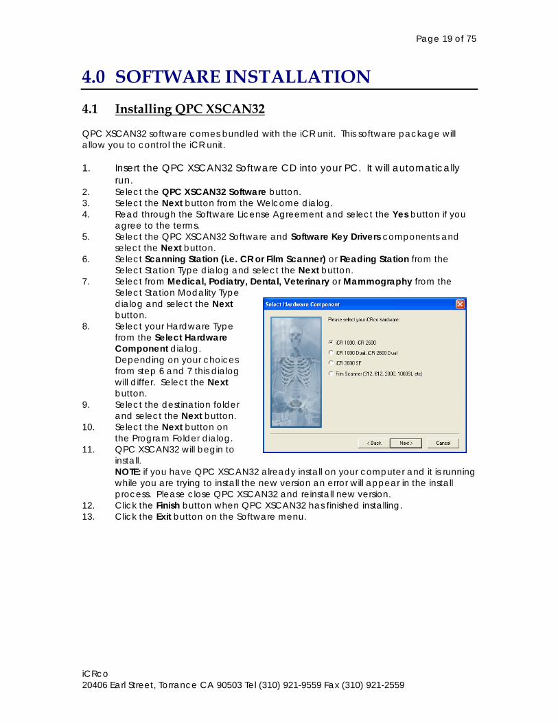
8. Select your Hardware Type from the Select Hardware Component dialog. Depending on your choices from step 6 and 7 this dialog will differ. Select the Next button.
9. Select the destination folder and select the Next button.
10. Select the Next button on the Program Folder dialog. 11. QPC XSCAN32 will begin to
install. NOTE: if you have QPC XSCAN32 already install on your computer and it is running while you are trying to install the new version an error will appear in the install process. Please close QPC XSCAN32 and reinstall new version.
12. Click the Finish button when QPC XSCAN32 has finished installing. 13. Click the Exit button on the Software menu.
Page 20 of 75
iCRco 20406 Earl Street, Torrance CA 90503 Tel (310) 921-9559 Fax (310) 921-2559
4.2 Installing the Applied Motion Products SCL Setup Utility You only have to install this if instructed by your service and support representative or iCRco technical support. 1. Insert the CD labeled “Applied Motion Products, Technical Resources CD” into
your CD-Rom drive. 2. On the main installation dialog select “install software”. 3. On the Install Software dialog select “SCL Setup Utility”. 4. The installation wizard will appear. Select Next on the Welcome dialog. 5. Select Next on the Select Program Folder dialog. The appropriate files will be
installed. 6. Select Exit on the main installation dialog.
Page 21 of 75
iCRco 20406 Earl Street, Torrance CA 90503 Tel (310) 921-9559 Fax (310) 921-2559
5.0 HARDWARE INSTALLATION 5.1 Hardware Installation for iCR 1000, iCR 2600, iCR Vet, iCR Chiro (2005 Model)
5.1.1 PC Specifications for iCR 1000, iCR 2600, iCR Vet, iCR Chiro (2005 Model)
The minimum requirements for the Q/C computer are as follows: Minimum Recommended Processor Pentium 4 RAM 512Mb 1 GB or more OS Win 2000PRO Windows XP HDD 80 GB 120 GB or more
5.1.2 USBII or DAC Installation for iCR 1000, iCR 2600, iCR Vet, iCR Chiro (2005 Model)
You must have followed the section 3.0 Installing Drivers before installing the board into the PC. For DAC boards you need to: 1. Turn the PC off. 2. Open the PC and find an available PCI slot. 3. Insert the data acquisition board. 4. Turn the PC back on. The drivers will auto load with the New Hardware Wizard. For iCR units with USBII support your PC will have a USB port.
5.1.3 Tools Required for iCR 1000, iCR 2600, iCR Vet, iCR Chiro (2005 Model)
Tool Used for #2 Philips-head screwdriver Installing and removing the eraser cover.
Accessing rear cover panel.
Page 22 of 75
iCRco 20406 Earl Street, Torrance CA 90503 Tel (310) 921-9559 Fax (310) 921-2559
5.1.4 Uncrating iCR 1000, iCR 2600, iCR Vet, iCR Chiro (2005 Model)
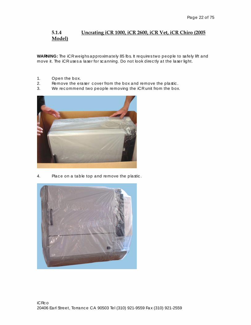
WARNING: The iCR weighs approximately 85 lbs. It requires two people to safely lift and move it. The iCR uses a laser for scanning. Do not look directly at the laser light.
1. Open the box. 2. Remove the eraser cover from the box and remove the plastic. 3. We recommend two people removing the iCR unit from the box.
4. Place on a table top and remove the plastic.
Page 23 of 75
iCRco 20406 Earl Street, Torrance CA 90503 Tel (310) 921-9559 Fax (310) 921-2559
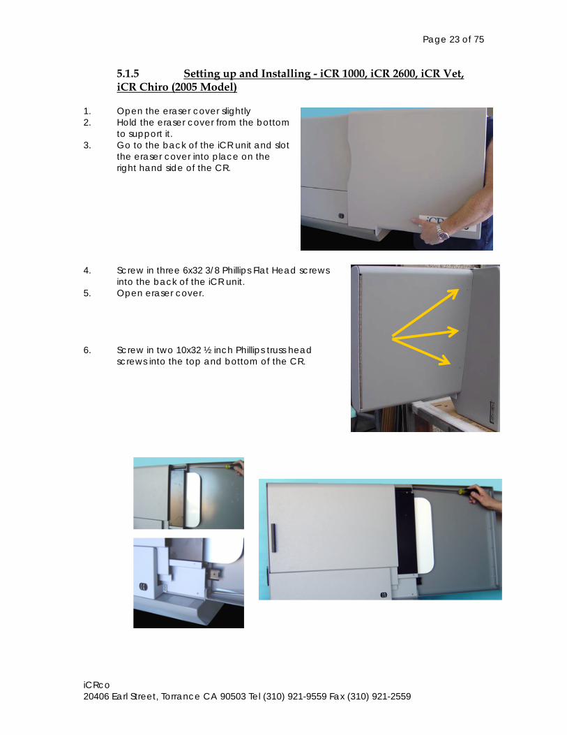
5.1.5 Setting up and Installing - iCR 1000, iCR 2600, iCR Vet, iCR Chiro (2005 Model)
1. Open the eraser cover slightly 2. Hold the eraser cover from the bottom
to support it. 3. Go to the back of the iCR unit and slot
the eraser cover into place on the right hand side of the CR.
4. Screw in three 6x32 3/8 Phillips Flat Head screws
into the back of the iCR unit. 5. Open eraser cover. 6. Screw in two 10x32 ½ inch Phillips truss head
screws into the top and bottom of the CR.
DSC00705.JPG
Page 24 of 75
iCRco 20406 Earl Street, Torrance CA 90503 Tel (310) 921-9559 Fax (310) 921-2559
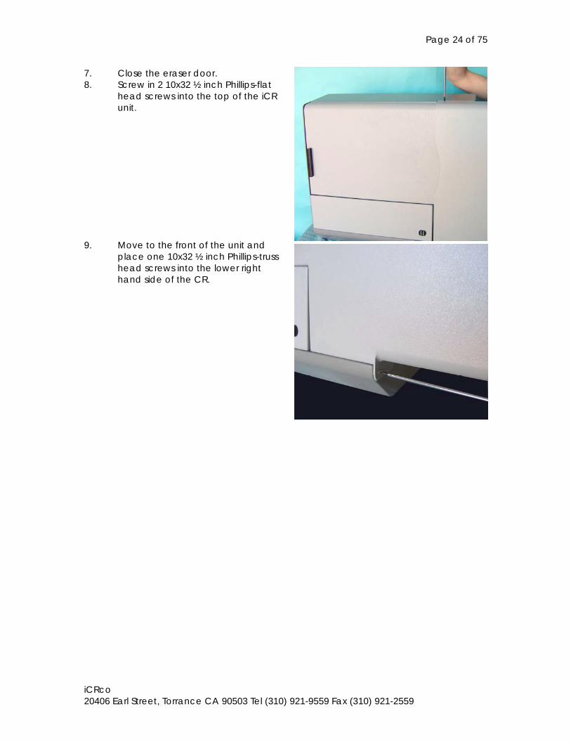
7. Close the eraser door. 8. Screw in 2 10x32 ½ inch Phillips-flat
head screws into the top of the iCR unit.
9. Move to the front of the unit and
place one 10x32 ½ inch Phillips-truss head screws into the lower right hand side of the CR.
Page 25 of 75
iCRco 20406 Earl Street, Torrance CA 90503 Tel (310) 921-9559 Fax (310) 921-2559
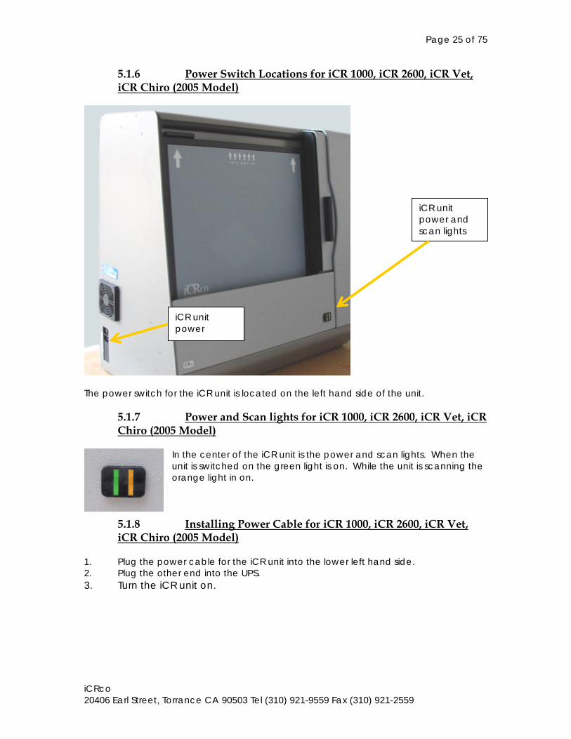
5.1.6 Power Switch Locations for iCR 1000, iCR 2600, iCR Vet, iCR Chiro (2005 Model)
The power switch for the iCR unit is located on the left hand side of the unit.
5.1.7 Power and Scan lights for iCR 1000, iCR 2600, iCR Vet, iCR Chiro (2005 Model)
In the center of the iCR unit is the power and scan lights. When the unit is switched on the green light is on. While the unit is scanning the orange light in on.
5.1.8 Installing Power Cable for iCR 1000, iCR 2600, iCR Vet, iCR Chiro (2005 Model)
1. Plug the power cable for the iCR unit into the lower left hand side. 2. Plug the other end into the UPS. 3. Turn the iCR unit on.
iCR unit power
iCR unit power and scan lights
Page 26 of 75
iCRco 20406 Earl Street, Torrance CA 90503 Tel (310) 921-9559 Fax (310) 921-2559
5.1.9 International Power Cable for iCR 1000, iCR 2600, iCR Vet, iCR Chiro (2005 Model)
The iCR unit utilizes an international IEC grade connector for the power cable. Systems are shipped with a standard NEMA 5-15 hospital grade cable. The cable needs to be changed depending on the male end, which varies from country to country. The machine has a universal power supply so there is no need to change any settings in the device for different power inputs. 5.2 Hardware Installation for iCR 1000 Dual, iCR 2600 Dual, iCR Vet Dual (2005 Model)
5.2.1 PC Specifications for iCR 1000 Dual, iCR 2600 Dual, iCR Vet Dual (2005 Model)
Refer to section 5.1.1.
5.2.2 USBII or DAC Installation for iCR 1000 Dual, iCR 2600 Dual, iCR Vet Dual (2005 Model)
Refer to section 5.1.2.
5.2.3 Tools Required for iCR 1000 Dual, iCR 2600 Dual, iCR Vet Dual (2005 Model)
Refer to section 5.1.3.
5.2.4 Uncrating the iCR 1000 Dual, iCR 2600 Dual, iCR Vet Dual (2005 Model)
Refer to section 5.1.4.
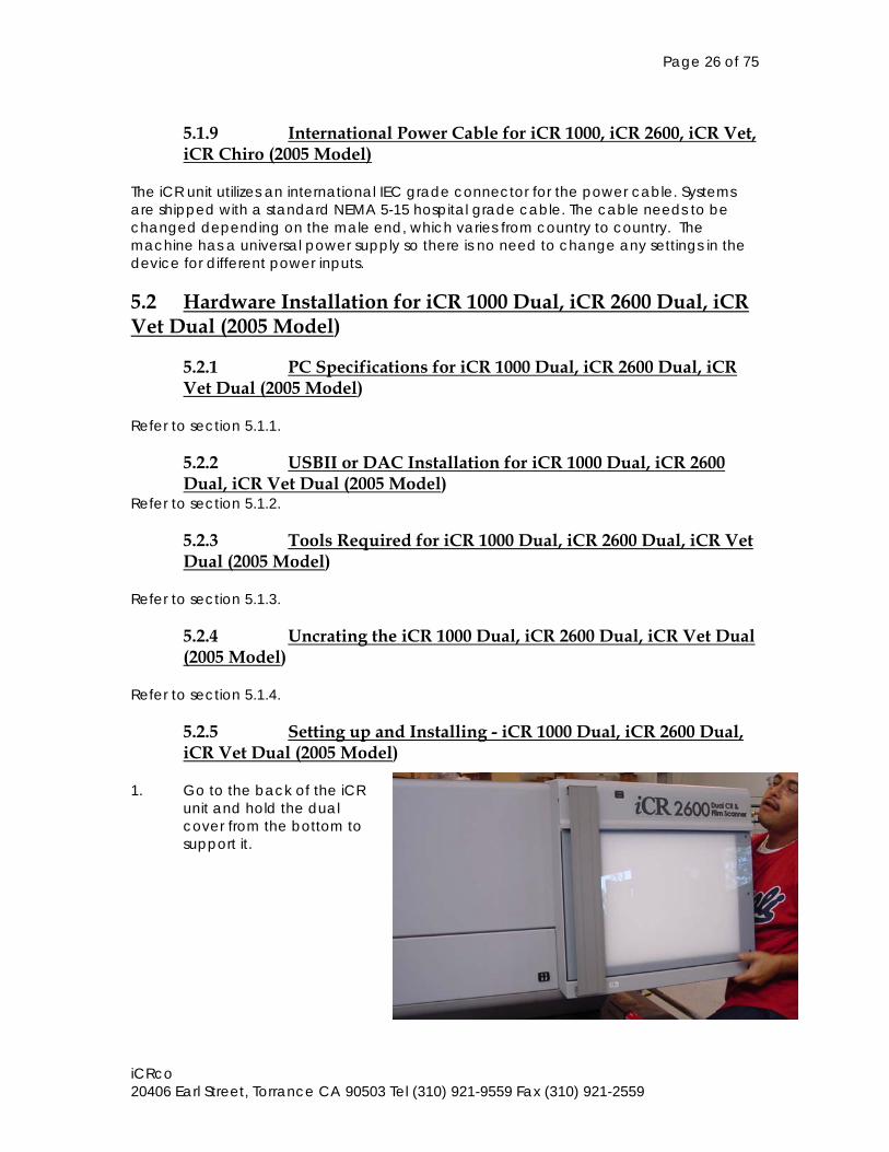
5.2.5 Setting up and Installing - iCR 1000 Dual, iCR 2600 Dual, iCR Vet Dual (2005 Model)
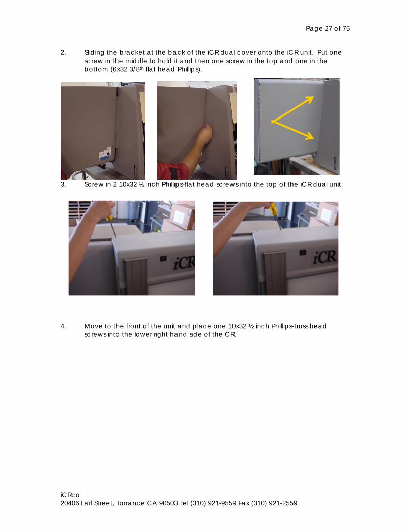
1. Go to the back of the iCR
unit and hold the dual cover from the bottom to support it.
Page 27 of 75
iCRco 20406 Earl Street, Torrance CA 90503 Tel (310) 921-9559 Fax (310) 921-2559
2. Sliding the bracket at the back of the iCR dual cover onto the iCR unit. Put one screw in the middle to hold it and then one screw in the top and one in the bottom (6x32 3/8th flat head Phillips).
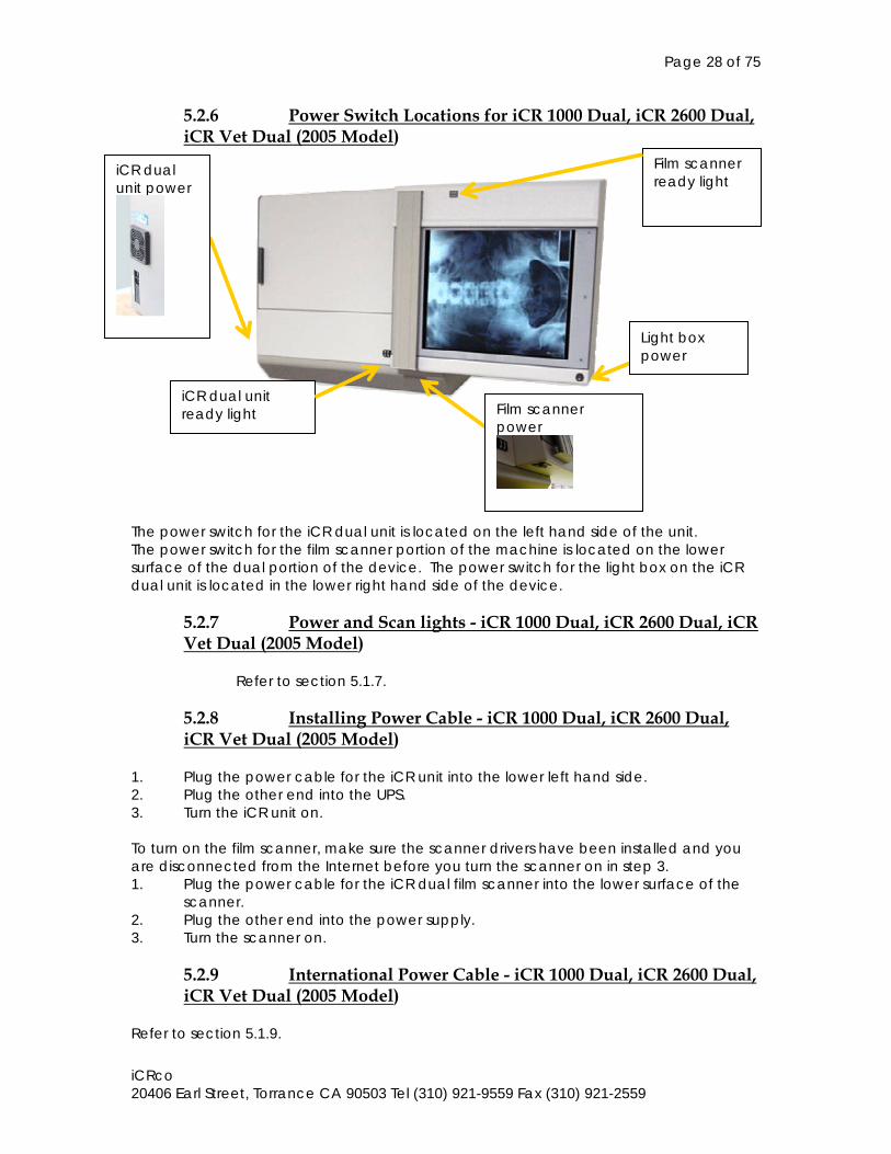
3. Screw in 2 10x32 ½ inch Phillips-flat head screws into the top of the iCR dual unit.
4. Move to the front of the unit and place one 10x32 ½ inch Phillips-truss head
screws into the lower right hand side of the CR.
Page 28 of 75
iCRco 20406 Earl Street, Torrance CA 90503 Tel (310) 921-9559 Fax (310) 921-2559
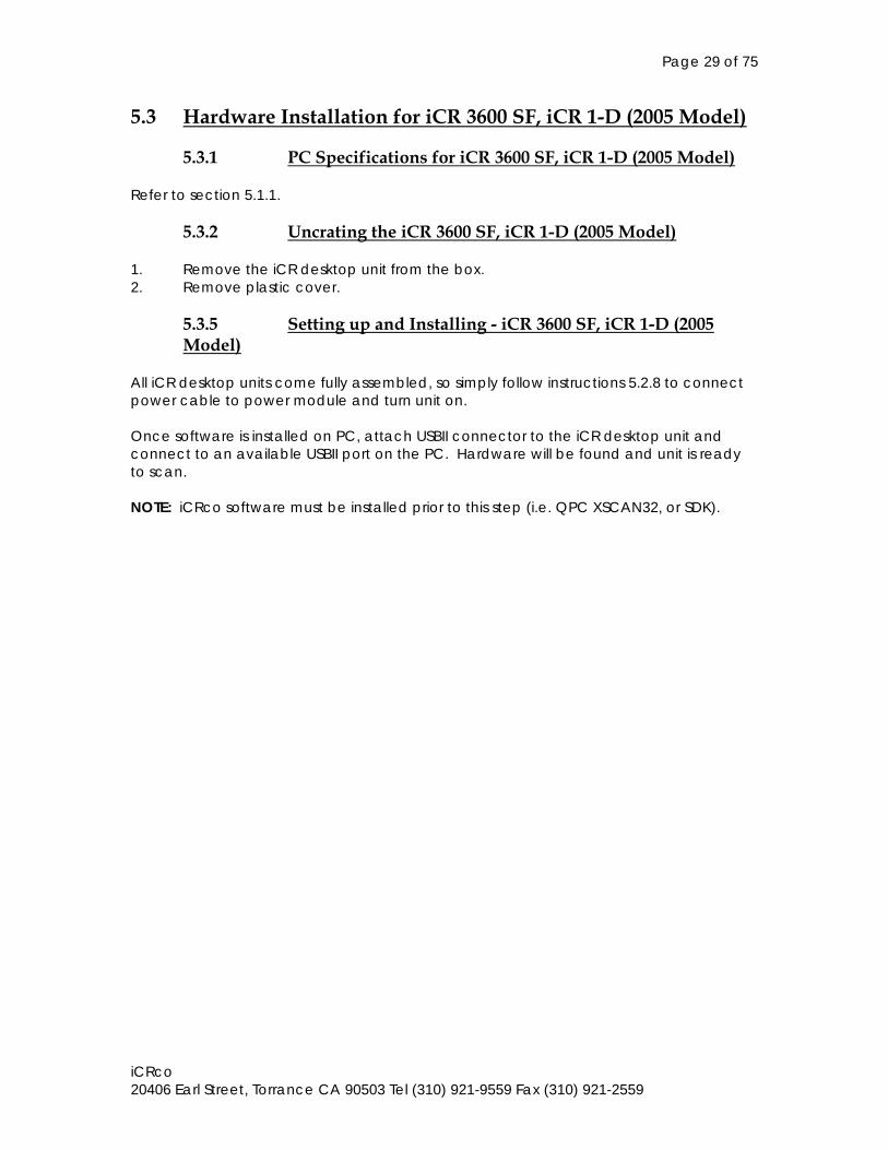
5.2.6 Power Switch Locations for iCR 1000 Dual, iCR 2600 Dual, iCR Vet Dual (2005 Model)
The power switch for the iCR dual unit is located on the left hand side of the unit. The power switch for the film scanner portion of the machine is located on the lower surface of the dual portion of the device. The power switch for the light box on the iCR dual unit is located in the lower right hand side of the device.
5.2.7 Power and Scan lights - iCR 1000 Dual, iCR 2600 Dual, iCR Vet Dual (2005 Model)
Refer to section 5.1.7.
5.2.8 Installing Power Cable - iCR 1000 Dual, iCR 2600 Dual, iCR Vet Dual (2005 Model)
1. Plug the power cable for the iCR unit into the lower left hand side. 2. Plug the other end into the UPS. 3. Turn the iCR unit on. To turn on the film scanner, make sure the scanner drivers have been installed and you are disconnected from the Internet before you turn the scanner on in step 3. 1. Plug the power cable for the iCR dual film scanner into the lower surface of the
scanner. 2. Plug the other end into the power supply. 3. Turn the scanner on.
5.2.9 International Power Cable - iCR 1000 Dual, iCR 2600 Dual, iCR Vet Dual (2005 Model)
Refer to section 5.1.9.
iCR dual unit power
Light box power
iCR dual unit ready light
Film scanner ready light
Film scanner power
Page 29 of 75
iCRco 20406 Earl Street, Torrance CA 90503 Tel (310) 921-9559 Fax (310) 921-2559
5.3 Hardware Installation for iCR 3600 SF, iCR 1-D (2005 Model)
5.3.1 PC Specifications for iCR 3600 SF, iCR 1-D (2005 Model) Refer to section 5.1.1.
5.3.2 Uncrating the iCR 3600 SF, iCR 1-D (2005 Model) 1. Remove the iCR desktop unit from the box. 2. Remove plastic cover.
5.3.5 Setting up and Installing - iCR 3600 SF, iCR 1-D (2005 Model)
All iCR desktop units come fully assembled, so simply follow instructions 5.2.8 to connect power cable to power module and turn unit on. Once software is installed on PC, attach USBII connector to the iCR desktop unit and connect to an available USBII port on the PC. Hardware will be found and unit is ready to scan. NOTE: iCRco software must be installed prior to this step (i.e. QPC XSCAN32, or SDK).
Page 30 of 75
iCRco 20406 Earl Street, Torrance CA 90503 Tel (310) 921-9559 Fax (310) 921-2559
5.4 Hardware Installation for iCR 1000, iCR 2600, iCR Vet (2004 model)
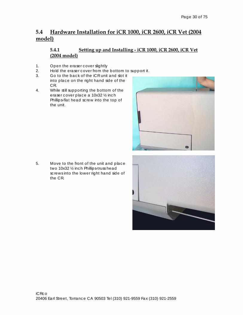
5.4.1 Setting up and Installing - iCR 1000, iCR 2600, iCR Vet (2004 model)
1. Open the eraser cover slightly 2. Hold the eraser cover from the bottom to support it. 3. Go to the back of the iCR unit and slot it
into place on the right hand side of the CR.
4. While still supporting the bottom of the eraser cover place a 10x32 ½ inch Phillips-flat head screw into the top of the unit.
5. Move to the front of the unit and place
two 10x32 ½ inch Phillips-truss head screws into the lower right hand side of the CR.
Page 31 of 75
iCRco 20406 Earl Street, Torrance CA 90503 Tel (310) 921-9559 Fax (310) 921-2559
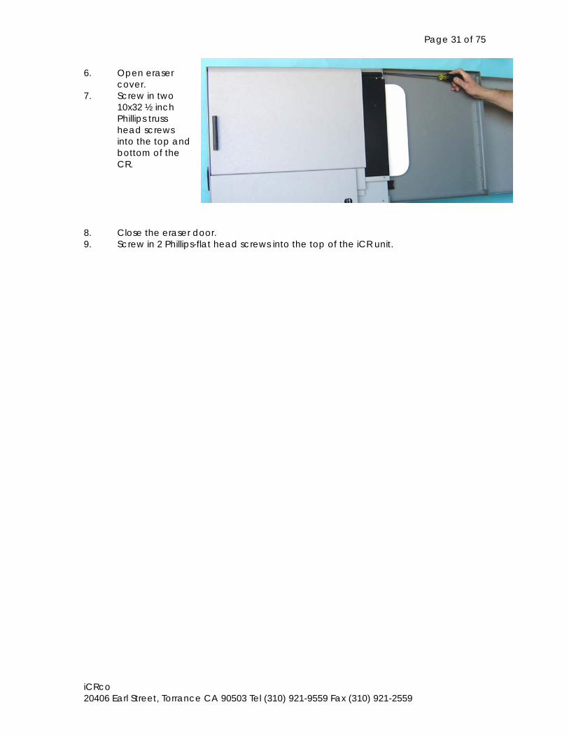
6. Open eraser cover. 7. Screw in two
10x32 ½ inch Phillips truss head screws into the top and bottom of the CR.
8. Close the eraser door. 9. Screw in 2 Phillips-flat head screws into the top of the iCR unit.
Page 32 of 75
iCRco 20406 Earl Street, Torrance CA 90503 Tel (310) 921-9559 Fax (310) 921-2559
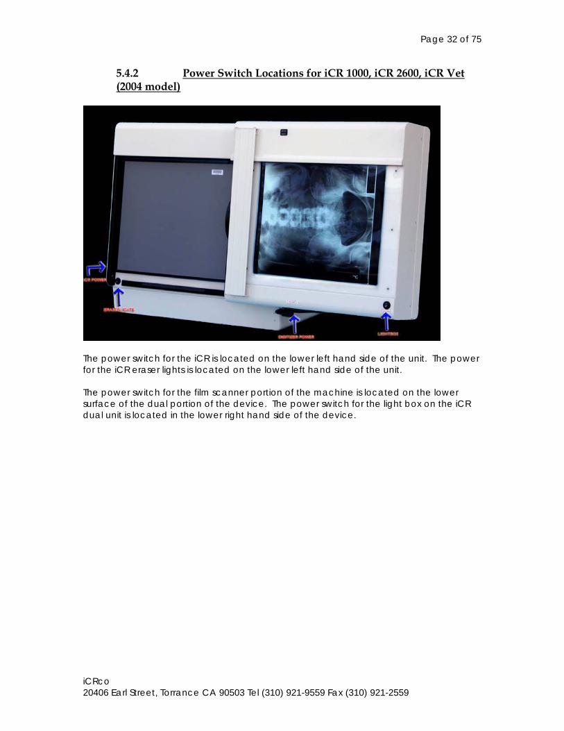
5.4.2 Power Switch Locations for iCR 1000, iCR 2600, iCR Vet (2004 model)
The power switch for the iCR is located on the lower left hand side of the unit. The power for the iCR eraser lights is located on the lower left hand side of the unit. The power switch for the film scanner portion of the machine is located on the lower surface of the dual portion of the device. The power switch for the light box on the iCR dual unit is located in the lower right hand side of the device.
Page 33 of 75
iCRco 20406 Earl Street, Torrance CA 90503 Tel (310) 921-9559 Fax (310) 921-2559
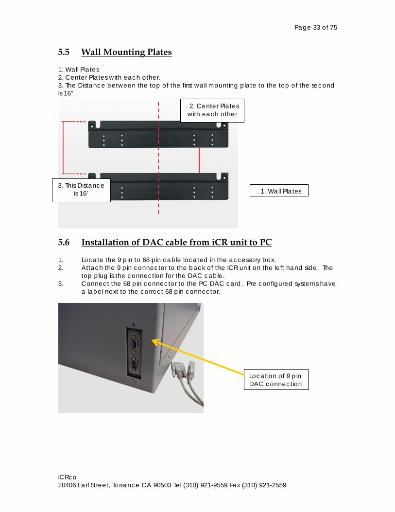
5.5 Wall Mounting Plates 1. Wall Plates 2. Center Plates with each other. 3. The Distance between the top of the first wall mounting plate to the top of the second is 16”.
5.6 Installation of DAC cable from iCR unit to PC 1. Locate the 9 pin to 68 pin cable located in the accessory box. 2. Attach the 9 pin connector to the back of the iCR unit on the left hand side. The
top plug is the connection for the DAC cable. 3. Connect the 68 pin connector to the PC DAC card. Pre configured systems have
a label next to the correct 68 pin connector.
Location of 9 pin DAC connection
. 2. Center Plates with each other
3. This Distance is 16’ . 1. Wall Plates
Page 34 of 75
iCRco 20406 Earl Street, Torrance CA 90503 Tel (310) 921-9559 Fax (310) 921-2559
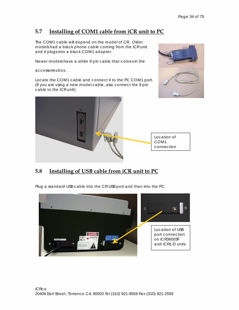
5.7 Installing of COM1 cable from iCR unit to PC The COM1 cable will depend on the model of CR. Older models had a black phone cable coming from the iCR unit and it plugs into a black COM1 adapter. Newer models have a white 9 pin cable that comes in the
accessories box. Locate the COM1 cable and connect it to the PC COM1 port. (If you are using a new model cable, also connect the 9 pin cable to the iCR unit).
5.8 Installing of USB cable from iCR unit to PC
Plug a standard USB cable into the CR USB port and then into the PC.
Location of COM1 connection
Location of USB port connection on iCR3600SF and iCR1-D units
Page 35 of 75
iCRco 20406 Earl Street, Torrance CA 90503 Tel (310) 921-9559 Fax (310) 921-2559
6.0 SYSTEM OPERATION
6.1 System Operation of iCR 1000, iCR 2600, iCR Vet, iCR Chiro (2005 Model)
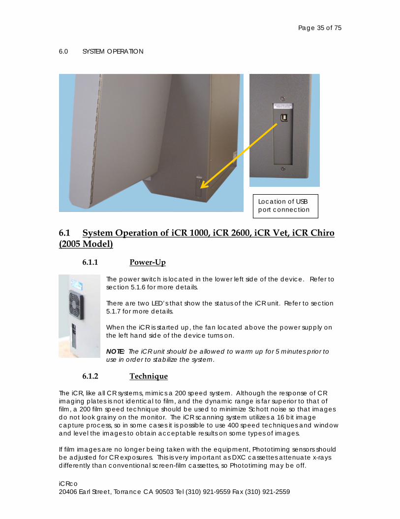
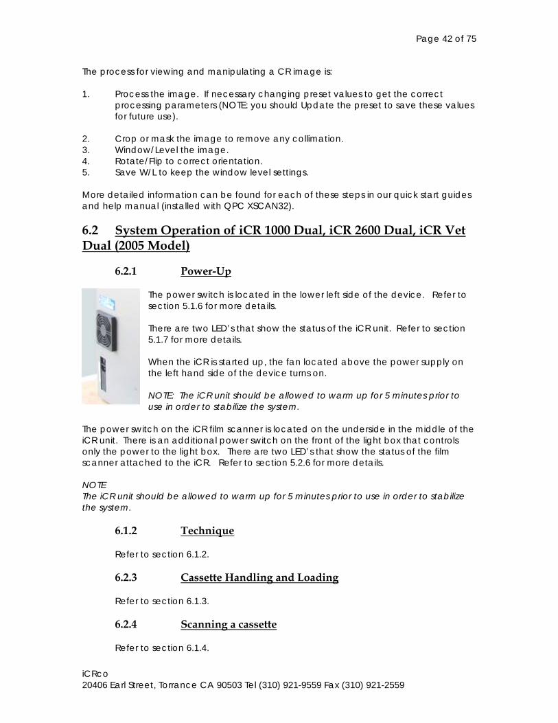
6.1.1 Power-Up The power switch is located in the lower left side of the device. Refer to section 5.1.6 for more details. There are two LED’s that show the status of the iCR unit. Refer to section 5.1.7 for more details. When the iCR is started up, the fan located above the power supply on the left hand side of the device turns on. NOTE: The iCR unit should be allowed to warm up for 5 minutes prior to use in order to stabilize the system.
6.1.2 Technique
The iCR, like all CR systems, mimics a 200 speed system. Although the response of CR imaging plates is not identical to film, and the dynamic range is far superior to that of film, a 200 film speed technique should be used to minimize Schott noise so that images do not look grainy on the monitor. The iCR scanning system utilizes a 16 bit image capture process, so in some cases it is possible to use 400 speed techniques and window and level the images to obtain acceptable results on some types of images. If film images are no longer being taken with the equipment, Phototiming sensors should be adjusted for CR exposures. This is very important as DXC cassettes attenuate x-rays differently than conventional screen-film cassettes, so Phototiming may be off.
Location of USB port connection
Page 36 of 75
iCRco 20406 Earl Street, Torrance CA 90503 Tel (310) 921-9559 Fax (310) 921-2559
99% of all CR imaging issues are related to improper technique. It is very important to calibrate the imaging system. Typically CR imaging systems reduce repeat exposures to below 5%, so additional exposure to a patient from retakes is minimized. GRIDS: The presence of a grid in a Bucky tray can cause issues with your images. If the grid is stationary you may need to change it to avoid artifacts (103 LPI Grids can cause a problem if they are not oscillating). 12 to 1 grids can cause issues because the grid factor can affect the dose to the patient.
Page 37 of 75
iCRco 20406 Earl Street, Torrance CA 90503 Tel (310) 921-9559 Fax (310) 921-2559
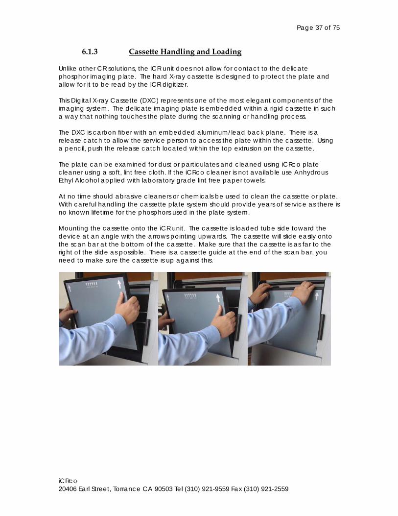
6.1.3 Cassette Handling and Loading Unlike other CR solutions, the iCR unit does not allow for contact to the delicate phosphor imaging plate. The hard X-ray cassette is designed to protect the plate and allow for it to be read by the ICR digitizer. This Digital X-ray Cassette (DXC) represents one of the most elegant components of the imaging system. The delicate imaging plate is embedded within a rigid cassette in such a way that nothing touches the plate during the scanning or handling process. The DXC is carbon fiber with an embedded aluminum/lead back plane. There is a release catch to allow the service person to access the plate within the cassette. Using a pencil, push the release catch located within the top extrusion on the cassette. The plate can be examined for dust or particulates and cleaned using iCRco plate cleaner using a soft, lint free cloth. If the iCRco cleaner is not available use Anhydrous Ethyl Alcohol applied with laboratory grade lint free paper towels. At no time should abrasive cleaners or chemicals be used to clean the cassette or plate. With careful handling the cassette plate system should provide years of service as there is no known lifetime for the phosphors used in the plate system. Mounting the cassette onto the iCR unit. The cassette is loaded tube side toward the device at an angle with the arrows pointing upwards. The cassette will slide easily onto the scan bar at the bottom of the cassette. Make sure that the cassette is as far to the right of the slide as possible. There is a cassette guide at the end of the scan bar, you need to make sure the cassette is up against this.
Page 38 of 75
iCRco 20406 Earl Street, Torrance CA 90503 Tel (310) 921-9559 Fax (310) 921-2559
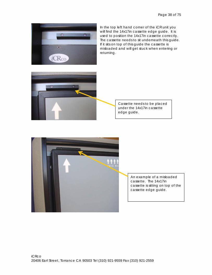
In the top left hand corner of the iCR unit you will find the 14x17in cassette edge guide. It is used to position the 14x17in cassette correctly. The cassette needs to sit underneath this guide. If it sits on top of this guide the cassette is misloaded and will get stuck when entering or returning.
Cassette needs to be placed under the 14x17in cassette edge guide.
An example of a misloaded cassette. The 14x17in cassette is sitting on top of the cassette edge guide.
Page 39 of 75
iCRco 20406 Earl Street, Torrance CA 90503 Tel (310) 921-9559 Fax (310) 921-2559
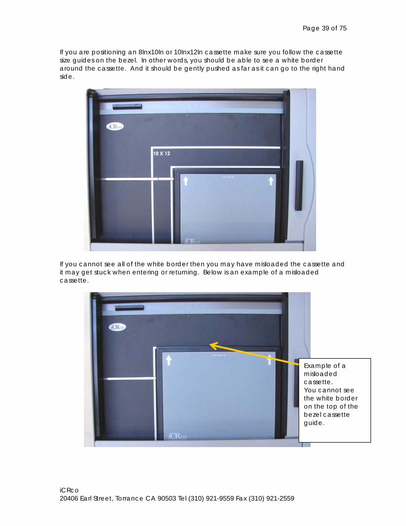
If you are positioning an 8Inx10In or 10Inx12In cassette make sure you follow the cassette size guides on the bezel. In other words, you should be able to see a white border around the cassette. And it should be gently pushed as far as it can go to the right hand side.
If you cannot see all of the white border then you may have misloaded the cassette and it may get stuck when entering or returning. Below is an example of a misloaded cassette.
Example of a misloaded cassette. You cannot see the white border on the top of the bezel cassette guide.
Page 40 of 75
iCRco 20406 Earl Street, Torrance CA 90503 Tel (310) 921-9559 Fax (310) 921-2559
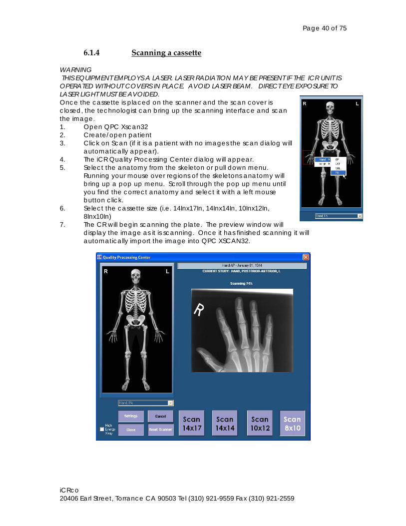
6.1.4 Scanning a cassette WARNING THIS EQUIPMENT EMPLOYS A LASER. LASER RADIATION MAY BE PRESENT IF THE ICR UNIT IS OPERATED WITHOUT COVERS IN PLACE. AVOID LASER BEAM. DIRECT EYE EXPOSURE TO LASER LIGHT MUST BE AVOIDED. Once the cassette is placed on the scanner and the scan cover is closed, the technologist can bring up the scanning interface and scan the image. 1. Open QPC Xscan32 2. Create/open patient 3. Click on Scan (if it is a patient with no images the scan dialog will
automatically appear). 4. The iCR Quality Processing Center dialog will appear. 5. Select the anatomy from the skeleton or pull down menu.
Running your mouse over regions of the skeletons anatomy will bring up a pop up menu. Scroll through the pop up menu until you find the correct anatomy and select it with a left mouse button click.
6. Select the cassette size (i.e. 14Inx17In, 14Inx14In, 10Inx12In, 8Inx10In)
7. The CR will begin scanning the plate. The preview window will display the image as it is scanning. Once it has finished scanning it will automatically import the image into QPC XSCAN32.
Page 41 of 75
iCRco 20406 Earl Street, Torrance CA 90503 Tel (310) 921-9559 Fax (310) 921-2559
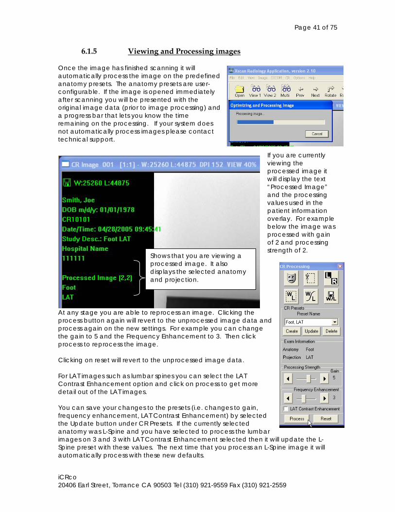
6.1.5 Viewing and Processing images Once the image has finished scanning it will automatically process the image on the predefined anatomy presets. The anatomy presets are user-configurable. If the image is opened immediately after scanning you will be presented with the original image data (prior to image processing) and a progress bar that lets you know the time remaining on the processing. If your system does not automatically process images please contact technical support.
If you are currently viewing the processed image it will display the text “Processed Image” and the processing values used in the patient information overlay. For example below the image was processed with gain of 2 and processing strength of 2.
At any stage you are able to reprocess an image. Clicking the process button again will revert to the unprocessed image data and process again on the new settings. For example you can change the gain to 5 and the Frequency Enhancement to 3. Then click process to reprocess the image. Clicking on reset will revert to the unprocessed image data. For LAT images such as lumbar spines you can select the LAT Contrast Enhancement option and click on process to get more detail out of the LAT images. You can save your changes to the presets (i.e. changes to gain, frequency enhancement, LAT Contrast Enhancement) by selected the Update button under CR Presets. If the currently selected anatomy was L-Spine and you have selected to process the lumbar images on 3 and 3 with LAT Contrast Enhancement selected then it will update the L-Spine preset with these values. The next time that you process an L-Spine image it will automatically process with these new defaults.
Shows that you are viewing a processed image. It also displays the selected anatomy and projection.
Page 42 of 75
iCRco 20406 Earl Street, Torrance CA 90503 Tel (310) 921-9559 Fax (310) 921-2559
The process for viewing and manipulating a CR image is: 1. Process the image. If necessary changing preset values to get the correct
processing parameters (NOTE: you should Update the preset to save these values for future use).
2. Crop or mask the image to remove any collimation. 3. Window/Level the image. 4. Rotate/Flip to correct orientation. 5. Save W/L to keep the window level settings. More detailed information can be found for each of these steps in our quick start guides and help manual (installed with QPC XSCAN32). 6.2 System Operation of iCR 1000 Dual, iCR 2600 Dual, iCR Vet Dual (2005 Model)
6.2.1 Power-Up The power switch is located in the lower left side of the device. Refer to section 5.1.6 for more details. There are two LED’s that show the status of the iCR unit. Refer to section 5.1.7 for more details. When the iCR is started up, the fan located above the power supply on the left hand side of the device turns on. NOTE: The iCR unit should be allowed to warm up for 5 minutes prior to use in order to stabilize the system.
The power switch on the iCR film scanner is located on the underside in the middle of the iCR unit. There is an additional power switch on the front of the light box that controls only the power to the light box. There are two LED’s that show the status of the film scanner attached to the iCR. Refer to section 5.2.6 for more details. NOTE The iCR unit should be allowed to warm up for 5 minutes prior to use in order to stabilize the system.
6.1.2 Technique
Refer to section 6.1.2.
6.2.3 Cassette Handling and Loading Refer to section 6.1.3.
6.2.4 Scanning a cassette
Refer to section 6.1.4.
Page 43 of 75
iCRco 20406 Earl Street, Torrance CA 90503 Tel (310) 921-9559 Fax (310) 921-2559
6.2.5 Viewing and Processing images
Refer to section 6.1.5. 6.3 System Operation of iCR 1000, iCR 2600, iCR Vet (2004 Model)
6.3.1 Power-Up Refer to section 6.1.1.
6.3.2 Technique Refer to section 6.1.2.
6.3.3 Cassette Handling and Loading Unlike other CR solutions, the iCR unit does not allow for contact to the delicate phosphor imaging plate. The hard X-ray cassette is designed to protect the plate and allow for it to be read by the ICR digitizer. This Digital X-ray Cassette (DXC) represents one of the most elegant components of the imaging system. The delicate imaging plate is embedded within a rigid cassette in such a way that nothing touches the plate during the scanning or handling process. The DXC is carbon fiber with an embedded aluminum/lead back plane and a patented attachment clip system along the top long side of the cassette. This attachment clip snaps onto the blue scan slide and forms a very rigid scan system that enables a flat, precise scan for absolute image fidelity. There is a release catch to allow the service person to access the plate within the cassette. Using a pencil, push the release catch located within the top extrusion on the cassette. The plate can be examined for dust or particulates and cleaned using iCRco plate cleaner using a soft, lint free cloth. If the iCRco cleaner is not available use Anhydrous Ethyl Alcohol applied with laboratory grade lint free paper towels. At no time should abrasive cleaners or chemicals be used to clean the cassette or plate. With careful handling the cassette plate system should provide years of service as there is no known lifetime for the phosphors used in the plate system.
Page 44 of 75
iCRco 20406 Earl Street, Torrance CA 90503 Tel (310) 921-9559 Fax (310) 921-2559
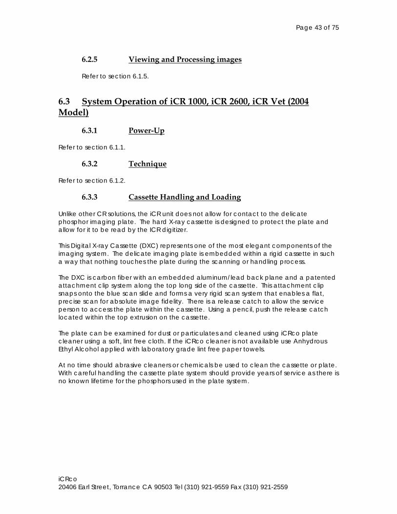
Mounting the cassette onto the iCR unit, the cassette is placed onto the scan bed in much the same way a film is placed on a light box. The cassette is located tube side down toward the device. The clip is located along the upper edge of the cassette. The cassette is lifted at an angle into the blue slide clip and rotated into place on the black bezel surface of the machine. Be sure that the cassette is pushed all the way up against the blue slide clip before the cassette is allowed to rotate onto the bezel plate.
6.3.4 Scanning a cassette
Refer to section 6.1.4. 6.3.5 Viewing and Processing images
Refer to section 6.1.5. 6.4 Quick Start Guides We provide quick start guides to all features of QPC XSCAN32. You can find these guides online at http://www.icrcompany.com/quickstart_downloads.html Alternatively you can contact technical support to request these guides to be emailed to you.
Page 45 of 75
iCRco 20406 Earl Street, Torrance CA 90503 Tel (310) 921-9559 Fax (310) 921-2559
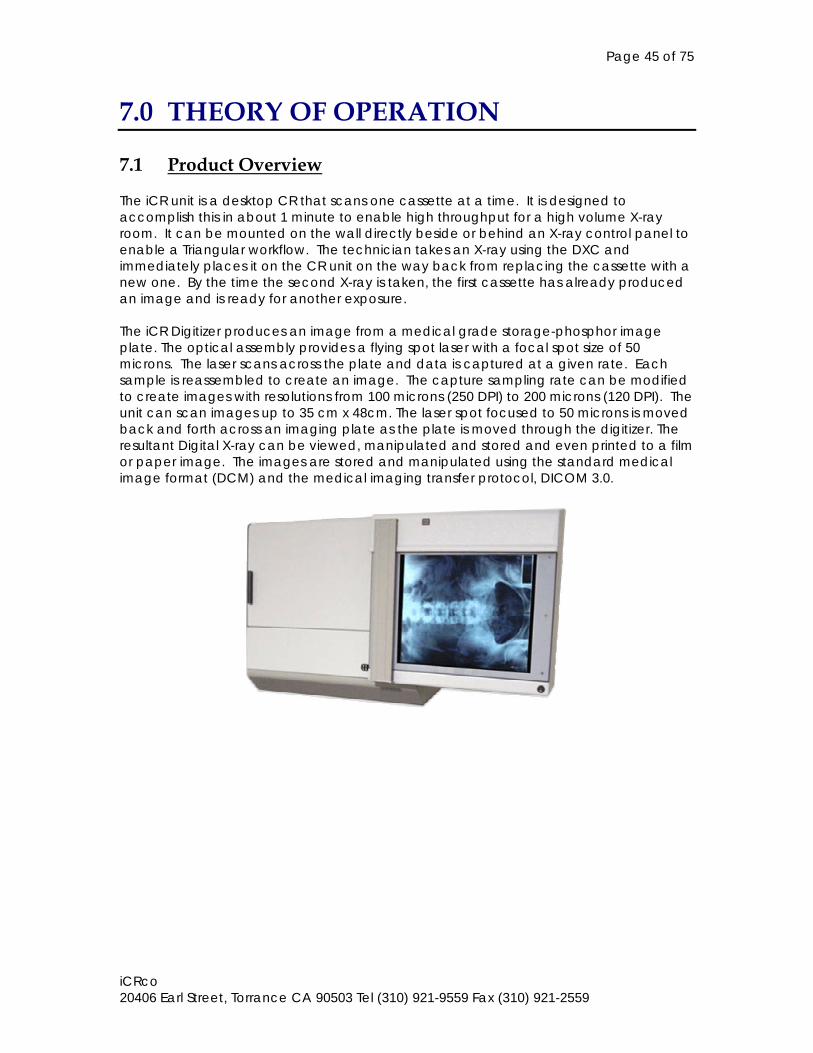
7.0 THEORY OF OPERATION 7.1 Product Overview The iCR unit is a desktop CR that scans one cassette at a time. It is designed to accomplish this in about 1 minute to enable high throughput for a high volume X-ray room. It can be mounted on the wall directly beside or behind an X-ray control panel to enable a Triangular workflow. The technician takes an X-ray using the DXC and immediately places it on the CR unit on the way back from replacing the cassette with a new one. By the time the second X-ray is taken, the first cassette has already produced an image and is ready for another exposure. The iCR Digitizer produces an image from a medical grade storage-phosphor image plate. The optical assembly provides a flying spot laser with a focal spot size of 50 microns. The laser scans across the plate and data is captured at a given rate. Each sample is reassembled to create an image. The capture sampling rate can be modified to create images with resolutions from 100 microns (250 DPI) to 200 microns (120 DPI). The unit can scan images up to 35 cm x 48cm. The laser spot focused to 50 microns is moved back and forth across an imaging plate as the plate is moved through the digitizer. The resultant Digital X-ray can be viewed, manipulated and stored and even printed to a film or paper image. The images are stored and manipulated using the standard medical image format (DCM) and the medical imaging transfer protocol, DICOM 3.0.
Page 46 of 75
iCRco 20406 Earl Street, Torrance CA 90503 Tel (310) 921-9559 Fax (310) 921-2559
7.2 System Configuration The ICR digitizer/ film scanner has two separate optics assemblies and their associated electrical and power supply modules. It also has 2 separate scan heads and transport assemblies.
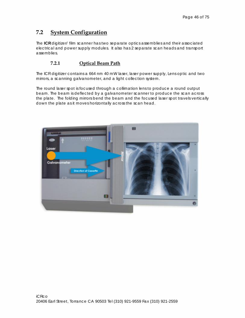
7.2.1 Optical Beam Path The ICR digitizer contains a 664 nm 40 mW laser, laser power supply, Lens optic and two mirrors, a scanning galvanometer, and a light collection system. The round laser spot is focused through a collimation lens to produce a round output beam. The beam is deflected by a galvanometer scanner to produce the scan across the plate. The folding mirrors bend the beam and the focused laser spot travels vertically down the plate as it moves horizontally across the scan head.
Page 47 of 75
iCRco 20406 Earl Street, Torrance CA 90503 Tel (310) 921-9559 Fax (310) 921-2559
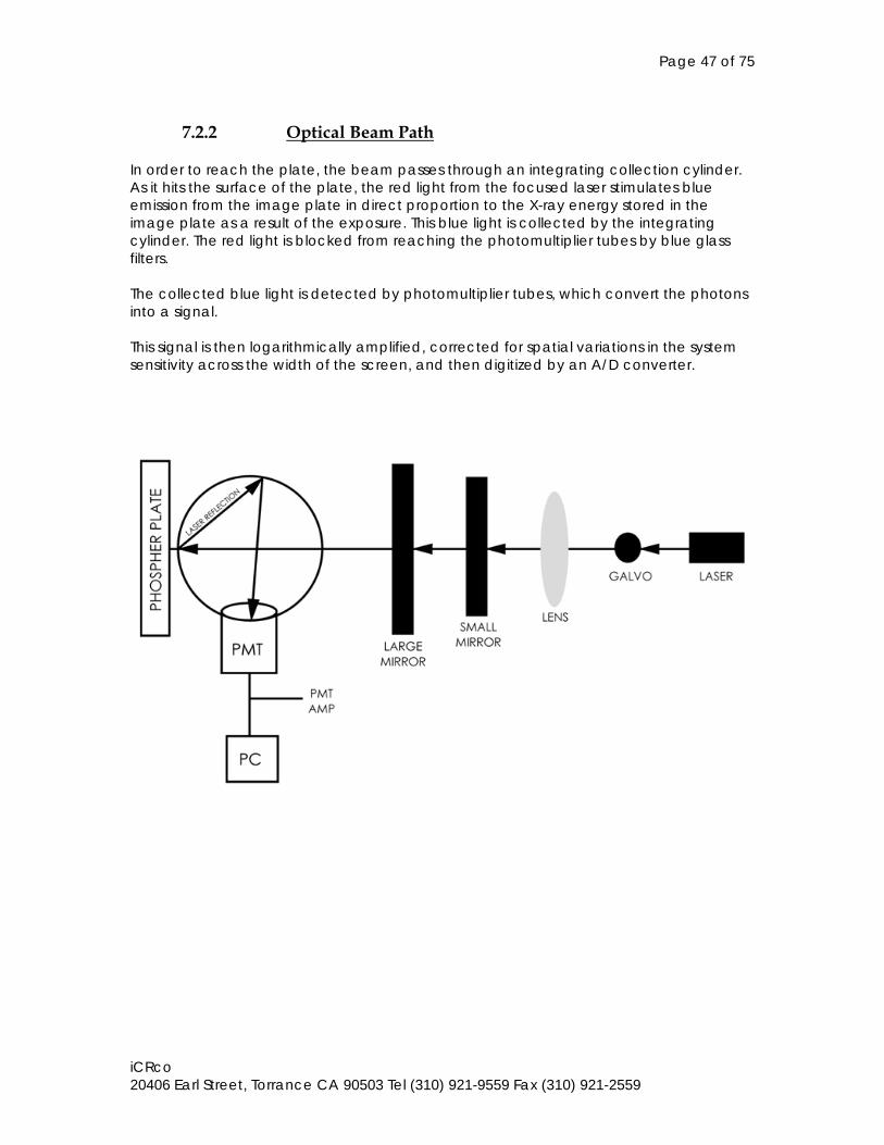
7.2.2 Optical Beam Path
In order to reach the plate, the beam passes through an integrating collection cylinder. As it hits the surface of the plate, the red light from the focused laser stimulates blue emission from the image plate in direct proportion to the X-ray energy stored in the image plate as a result of the exposure. This blue light is collected by the integrating cylinder. The red light is blocked from reaching the photomultiplier tubes by blue glass filters. The collected blue light is detected by photomultiplier tubes, which convert the photons into a signal. This signal is then logarithmically amplified, corrected for spatial variations in the system sensitivity across the width of the screen, and then digitized by an A/D converter.
Page 48 of 75
iCRco 20406 Earl Street, Torrance CA 90503 Tel (310) 921-9559 Fax (310) 921-2559
7.3 Digital and Electrical Systems The electrical subsystem of the ICR DITIGIZER consists of the Data Control Board, (DCB), that is located in a PC-type host computer an interconnecting cable to the iCR Film Scanner, and the scanner, which houses six printed circuit boards. These include: Data Acquisition Board (DACQ), PMT PreAmp Board, Galvanometer Board, Indicator Board. Indicator/ff Interface Board Reference LED Board
7.3.1 Data Acquisition Board The DAC is a PCI card that fits into the computer. It is a full size card so the computer has to have the proper space for the card. A mini-tower configuration is preferred. The DAC performs all the signal conditioning and data acquisition functions, including calibration and lookup table functions.
7.3.2 PMT PreAmp Board The PMT PreAmp Board contains the first stage preamplifier. This board provides power connection, a high voltage divider network for the PMT tubes and a first stage amplifier for the PMT signals.
7.3.3 Galvanometer Board The Galvo board contains a high-accuracy feedback servo amplifier for controlling the position of a mirror mounted on the shaft of a scanning galvanometer. Position feedback is from a sensor integral to the galvo. The galvo motor shaft oscillates back and forth through an arc of approximately 30 degrees at a rate of 50Hz, 65Hz, or 70Hz depending on your CR. Your CR settings will let you know which. A small mirror attached to the shaft intercepts the static laser beam and sweeps (scans) it across the width of the image plate. It is important that the Galvanometer Board be adjusted so that the beam scans across the plate at a consistent speed. Proper performance of the Galvo PCB is dependent upon the adjustment of several of its potentiometers.
7.3.4 Indicator Board The Indicator Board contains two LED indicator lamps which are used to signal scanner power ON and SCAN status. The SCAN indicator is turned on only while a scan is in process; it also blinks whenever the plate is in the optical path.
7.3.5 Indicator/FF Interface Board The Indicator/FF Interface Board provides an adjustable drive circuit for the Reference LED Board.
Page 49 of 75
iCRco 20406 Earl Street, Torrance CA 90503 Tel (310) 921-9559 Fax (310) 921-2559
7.3.6 Reference LED Board
The Reference LED Board provides a means of mounting the blue reference LED and a connector. The blue LED provides a consistent reference signal for purposes of self-alignment by the electronics.
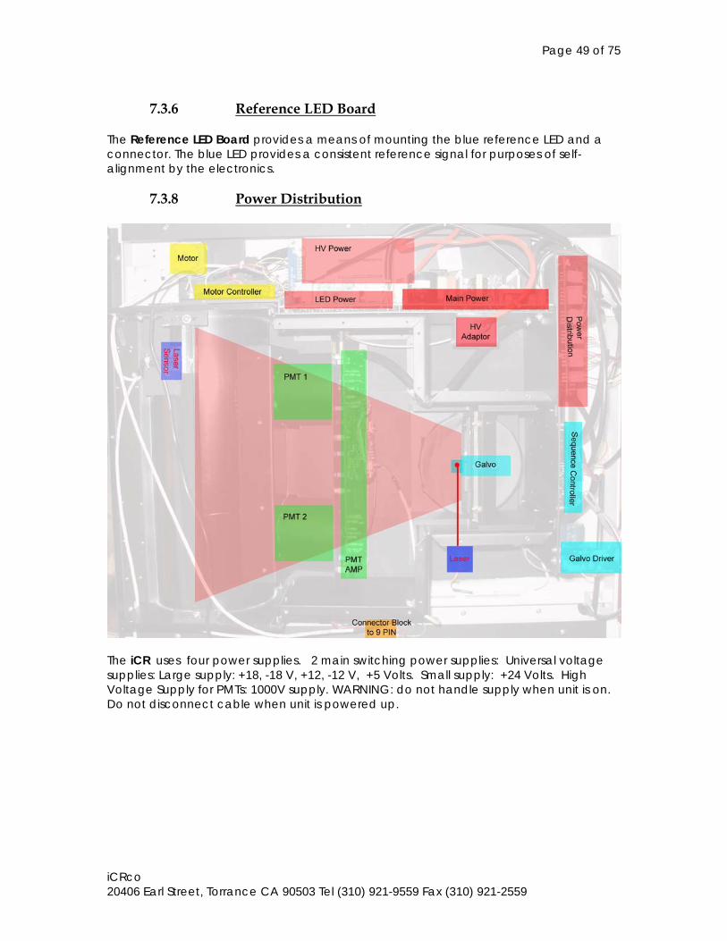
7.3.8 Power Distribution
The iCR uses four power supplies. 2 main switching power supplies: Universal voltage supplies: Large supply: +18, -18 V, +12, -12 V, +5 Volts. Small supply: +24 Volts. High Voltage Supply for PMTs: 1000V supply. WARNING: do not handle supply when unit is on. Do not disconnect cable when unit is powered up.
Page 50 of 75
iCRco 20406 Earl Street, Torrance CA 90503 Tel (310) 921-9559 Fax (310) 921-2559
7.4 Sub-System Operation
7.4.1 ADC Board Control During Scanning During the scanning process signals are generated by the PMT sensors and transmitted to the DAC card. A trigger signal generated by the laser spot is transmitted to the DAC card to trigger a line capture. Image is assembled from lines of captured data that is held in registers and translated into a 16 bit raw source file. There is no way to pause the data capture process. Cancel will cause the machine to stop and return to home position. Data on the CR plate will be lost. NOTE: If an image is cancelled during the scan process, the plate will have to be erased again to ensure that the plate is entirely erased.
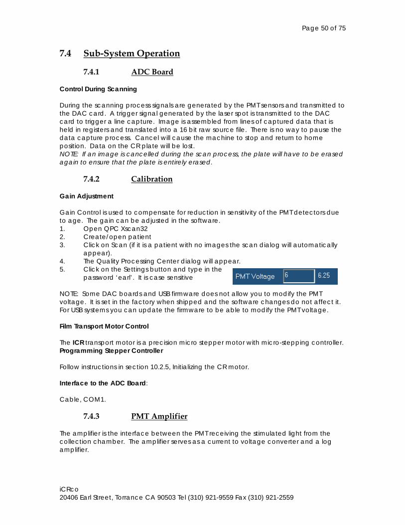
7.4.2 Calibration Gain Adjustment Gain Control is used to compensate for reduction in sensitivity of the PMT detectors due to age. The gain can be adjusted in the software. 1. Open QPC Xscan32 2. Create/open patient 3. Click on Scan (if it is a patient with no images the scan dialog will automatically
appear). 4. The Quality Processing Center dialog will appear. 5. Click on the Settings button and type in the
password ‘earl’. It is case sensitive NOTE: Some DAC boards and USB firmware does not allow you to modify the PMT voltage. It is set in the factory when shipped and the software changes do not affect it. For USB systems you can update the firmware to be able to modify the PMT voltage. Film Transport Motor Control The ICR transport motor is a precision micro stepper motor with micro-stepping controller. Programming Stepper Controller Follow instructions in section 10.2.5, Initializing the CR motor. Interface to the ADC Board: Cable, COM1.
7.4.3 PMT Amplifier The amplifier is the interface between the PMT receiving the stimulated light from the collection chamber. The amplifier serves as a current to voltage converter and a log amplifier.
Page 51 of 75
iCRco 20406 Earl Street, Torrance CA 90503 Tel (310) 921-9559 Fax (310) 921-2559
8.0 SERVICE ADJUSTMENTS This section covers the ICR SERVICE MANUAL components that can be adjusted in the field. WARNING: Use of X-ray equipment must be supervised by trained, qualified personnel. Lead shielding must be present in an X-ray test room. Do not open cover and test ICR in brightly lit room. Darkened room only with black cloth covering for testing. 8.1 Optics This procedure contains complete field optical alignment instructions for the ICR Laser light will be on. Please follow all warnings and cautions listed in the Introduction, Installation and Maintenance sections of this manual. Changing any module in the optical path will require a realignment of the optical system. All optics surfaces are extremely sensitive to any abrasion and should be cleaned using an optical grade cloth (not a lint cleaning cloth). Optical Adjustments: NOTE: The following alignment procedures are not required unless a component used in the procedure has been replaced. Alignment should not be attempted unless the service engineer has been factory trained. 1. Laser Light 2. Folding Mirrors (Long and short mirrors inside back optical cavity) 3. Laser Sensor Alignment 8.2 PMT Sub System This section provides the method of adjusting the System for alignment or after replacement of the PMT tubes or PMT amp. NOTE: Allow the iCR to warm up for at least 5 minutes prior to making any adjustments. CAUTION: When making these adjustments, be aware that the Photomultiplier tube is EXTREMELY sensitive to light. When you remove the cover, use a photographic dark cloth to prevent ambient light from damaging the tube or effecting your gain adjustment. PMT Output Voltage Adjustment 1. Disconnect the High Voltage connector. 2. Open QPC Xscan32 3. Create/open patient 4. Click on Scan (if it is a patient with no images the scan dialog will automatically
appear). 5. The iCR Quality Processing Center dialog will appear. 6. Click on the Settings button 7. Type in the password ‘earl’. It is case sensitive 8. Click on the Focus button 4. Adjust the offset potentiometer RXX on the PMT Board so that the line in the focus
dialog is located close to 0.

Page 52 of 75
iCRco 20406 Earl Street, Torrance CA 90503 Tel (310) 921-9559 Fax (310) 921-2559
9.0 PERIODIC MAINTENANCE System Maintenance is classified in four categories, Daily Maintenance, Routine Maintenance, Periodic Cleaning and Periodic Gain Check. Daily Maintenance and Routine Maintenance are normally performed by the system operator. Periodic Cleaning and Periodic Gain Check are performed by a trained service engineer. Clean area around the system daily. Check for dust. 9.1 Periodic Cleaning WARNING: IT IS IMPORTANT THAT THE COVERS REMAIN ON THE SYSTEM AT ALL TIMES. THE COVERS SHOULD ONLY BE REMOVED FOR SERVICE, AND THEN IMMEDIATELY REPLACED. THIS WILL MINIMIZE DUST ENTRY.
DANGER: THIS EQUIPMENT EMPLOYS A LASER. LASER RADIATION MAY BE PRESENT IF THE iCR READER IS OPERATED WITHOUT COVERS. AVOID LASER BEAM. DIRECT EYE EXPOSURE TO LASER LIGHT MUST BE AVOIDED.
CAUTION: BE SURE TO USE PROPER ESD PRACTICE WHEN TOUCHING ELECTRICAL COMPONENTS IN THE iCR WITH THE COVERS OFF. CAUTION: DO NOT CLEAN THE GALVO MIRROR. DUST AND FIBERS IN THE LASER BEAM PATH MAY AFFECT THE RADIOGRAPHIC IMAGE.
The outside covers of the iCR unit should be cleaned with Simple Green® and Ball® SUN-UP® glass cleaner or Sprayway© glass cleaner. Do not spray cleaner directly on the iCR covers. Spray on a soft, clean cloth, and then wipe down the covers. 1. The main objective is to remove particles that may cause vertical lines in images. 2. Digitize an image for comparison with performance after cleaning. 3. Remove the main back cover. 4. Remove the fan filter and clean with warm soapy water. 5. Remove the front cover. 6 Vacuum the interior.
Recommended cleaning products
Page 53 of 75
iCRco 20406 Earl Street, Torrance CA 90503 Tel (310) 921-9559 Fax (310) 921-2559
7. Clean the laser entry slot of the light collection chamber with lens tissue and a compressed gas duster.
8. Remove any lint that may be adhering to the laser output slot. Use lens tissue and a compressed gas duster.
9. Digitize an image and check for vertical lines. If lines remain, look for lint and particles corresponding to the position of the remaining lines. A flashlight can be used to illuminate lint particles.
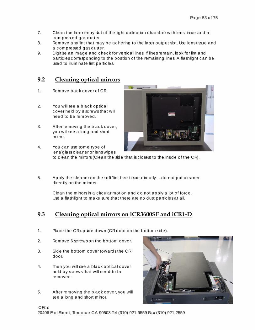
9.2 Cleaning optical mirrors 1. Remove back cover of CR. 2. You will see a black optical
cover held by 8 screws that will need to be removed.
3. After removing the black cover,
you will see a long and short mirror.
4. You can use some type of
lens/glass cleaner or lens wipes to clean the mirrors (Clean the side that is closest to the inside of the CR).
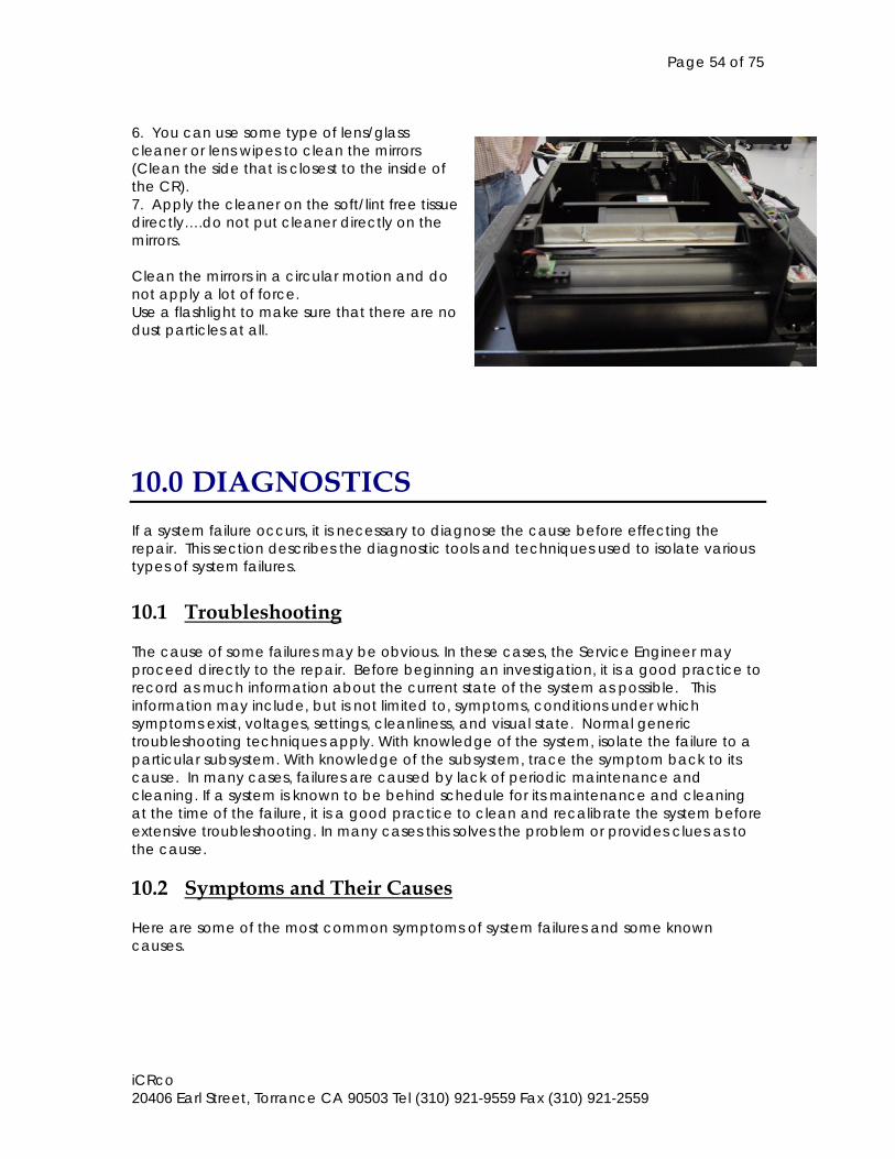
5. Apply the cleaner on the soft/lint free tissue directly….do not put cleaner directly on the mirrors. Clean the mirrors in a circular motion and do not apply a lot of force. Use a flashlight to make sure that there are no dust particles at all. 9.3 Cleaning optical mirrors on iCR3600SF and iCR1-D 1. Place the CR upside down (CR door on the bottom side). 2. Remove 6 screws on the bottom cover. 3. Slide the bottom cover towards the CR
door. 4. Then you will see a black optical cover
held by screws that will need to be removed.
5. After removing the black cover, you will
see a long and short mirror.
Page 54 of 75
iCRco 20406 Earl Street, Torrance CA 90503 Tel (310) 921-9559 Fax (310) 921-2559
6. You can use some type of lens/glass cleaner or lens wipes to clean the mirrors (Clean the side that is closest to the inside of the CR). 7. Apply the cleaner on the soft/lint free tissue directly….do not put cleaner directly on the mirrors. Clean the mirrors in a circular motion and do not apply a lot of force. Use a flashlight to make sure that there are no dust particles at all.
10.0 DIAGNOSTICS If a system failure occurs, it is necessary to diagnose the cause before effecting the repair. This section describes the diagnostic tools and techniques used to isolate various types of system failures. 10.1 Troubleshooting The cause of some failures may be obvious. In these cases, the Service Engineer may proceed directly to the repair. Before beginning an investigation, it is a good practice to record as much information about the current state of the system as possible. This information may include, but is not limited to, symptoms, conditions under which symptoms exist, voltages, settings, cleanliness, and visual state. Normal generic troubleshooting techniques apply. With knowledge of the system, isolate the failure to a particular subsystem. With knowledge of the subsystem, trace the symptom back to its cause. In many cases, failures are caused by lack of periodic maintenance and cleaning. If a system is known to be behind schedule for its maintenance and cleaning at the time of the failure, it is a good practice to clean and recalibrate the system before extensive troubleshooting. In many cases this solves the problem or provides clues as to the cause. 10.2 Symptoms and Their Causes Here are some of the most common symptoms of system failures and some known causes.
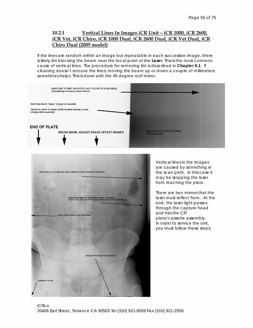
Page 55 of 75
iCRco 20406 Earl Street, Torrance CA 90503 Tel (310) 921-9559 Fax (310) 921-2559
10.2.1 Vertical Lines In Images iCR Unit – iCR 1000, iCR 2600, iCR Vet, iCR Chiro, iCR 1000 Dual, iCR 2600 Dual, iCR Vet Dual, iCR Chiro Dual (2005 model)
If the lines are random within an image but repeatable in each successive image, there is likely lint blocking the beam near the focal point of the Laser. This is the most common cause of vertical lines. The procedure for removing lint is described in Chapter 9.1. If cleaning doesn’t remove the lines, moving the beam up or down a couple of millimeters sometimes helps. This is done with the 45 degree roof mirror.
Vertical lines in the images are caused by something in the scan path. In this case it may be stopping the laser from reaching the plate. There are two mirrors that the laser must reflect from. At the end, the laser light passes through the capture head and hits the CR plate/cassette assembly. In order to service the unit, you must follow these steps:
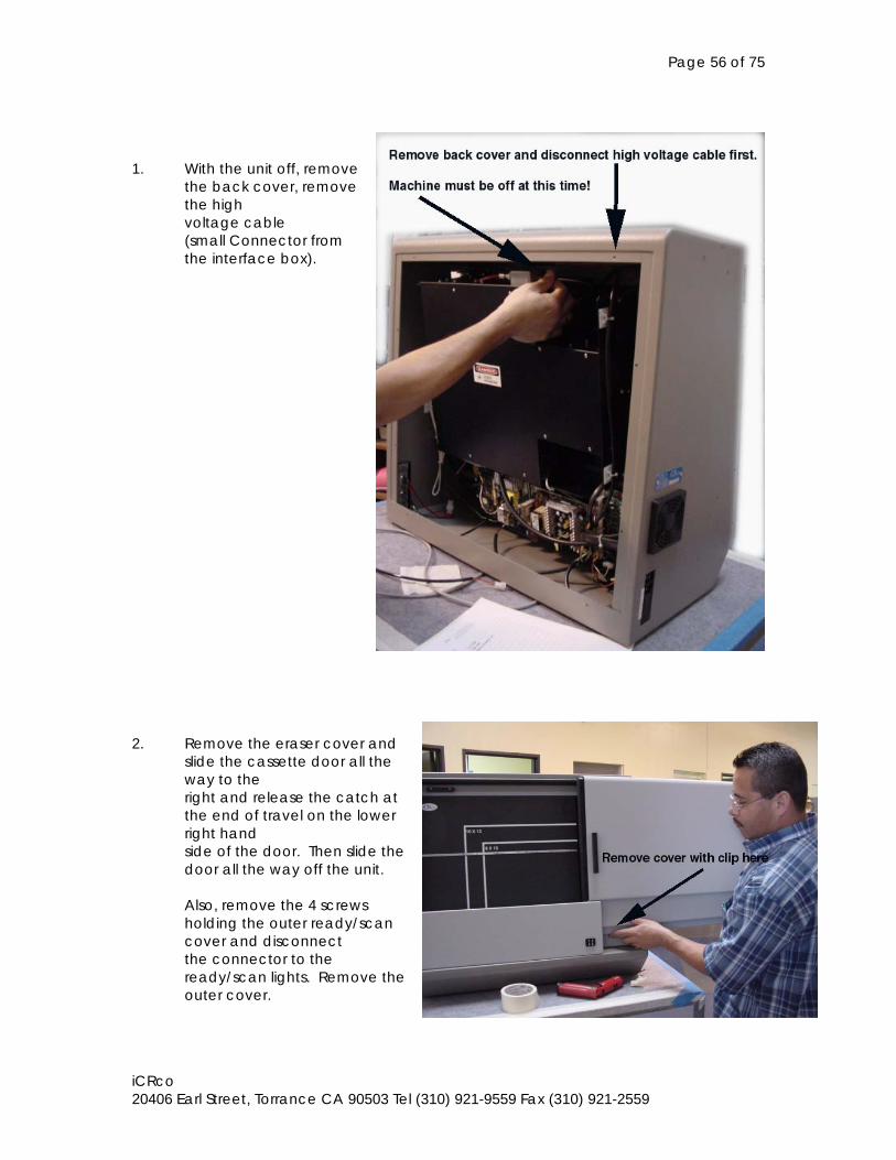
Page 56 of 75
iCRco 20406 Earl Street, Torrance CA 90503 Tel (310) 921-9559 Fax (310) 921-2559
1. With the unit off, remove
the back cover, remove the high voltage cable (small Connector from the interface box).
2. Remove the eraser cover and
slide the cassette door all the way to the right and release the catch at the end of travel on the lower right hand side of the door. Then slide the door all the way off the unit. Also, remove the 4 screws holding the outer ready/scan cover and disconnect the connector to the ready/scan lights. Remove the outer cover.
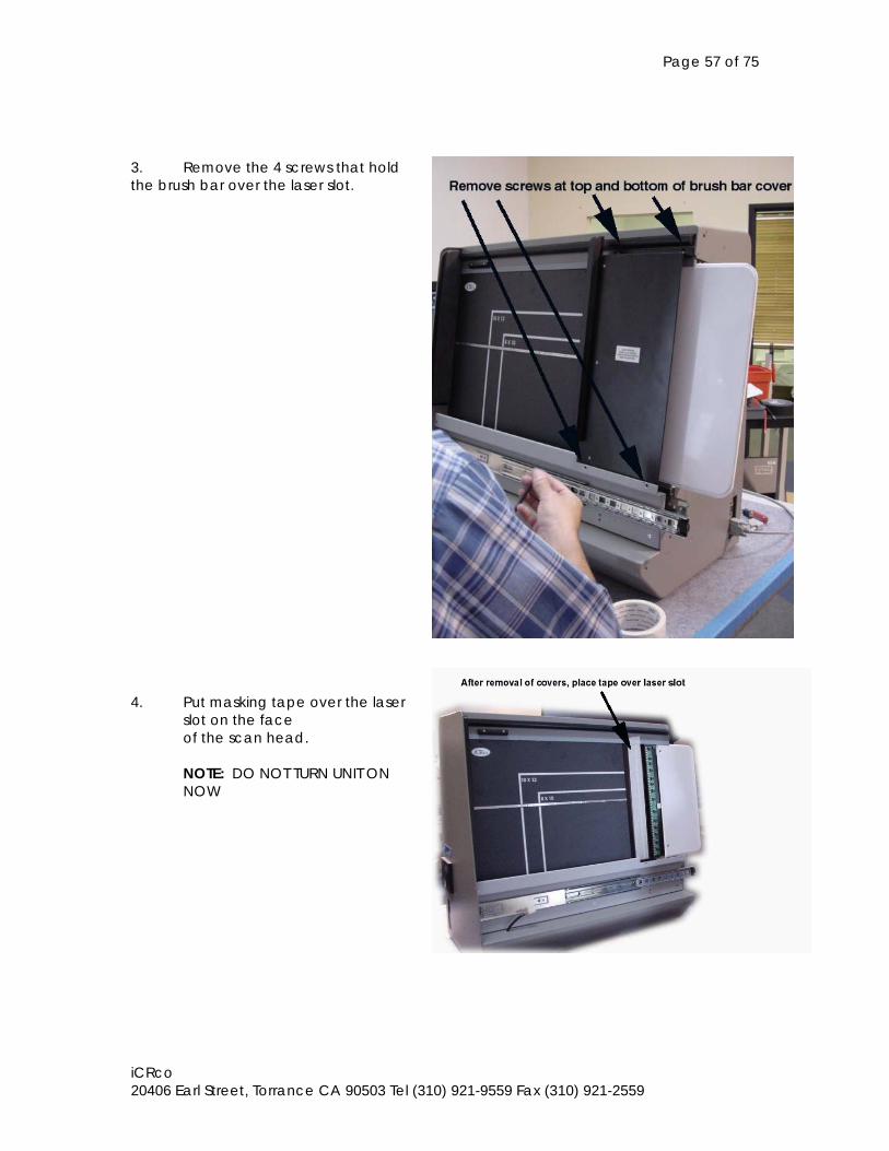
Page 57 of 75
iCRco 20406 Earl Street, Torrance CA 90503 Tel (310) 921-9559 Fax (310) 921-2559
3. Remove the 4 screws that hold the brush bar over the laser slot. 4. Put masking tape over the laser
slot on the face of the scan head. NOTE: DO NOT TURN UNIT ON NOW
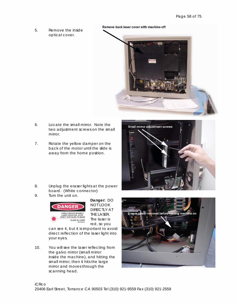
Page 58 of 75
iCRco 20406 Earl Street, Torrance CA 90503 Tel (310) 921-9559 Fax (310) 921-2559
5. Remove the inside optical cover.
6. Locate the small mirror. Note the
two adjustment screws on the small mirror.
7. Rotate the yellow damper on the
back of the motor until the slide is away from the home position.
8. Unplug the eraser lights at the power
board. (White connector) 9. Turn the unit on.
Danger: DO NOT LOOK DIRECTLY AT THE LASER.
The laser is red, so you
can see it, but it is important to avoid direct reflection of the laser light into your eyes.
10. You will see the laser reflecting from
the galvo mirror (small mirror inside the machine), and hitting the small mirror, then it hits the large mirror and moves through the scanning head.
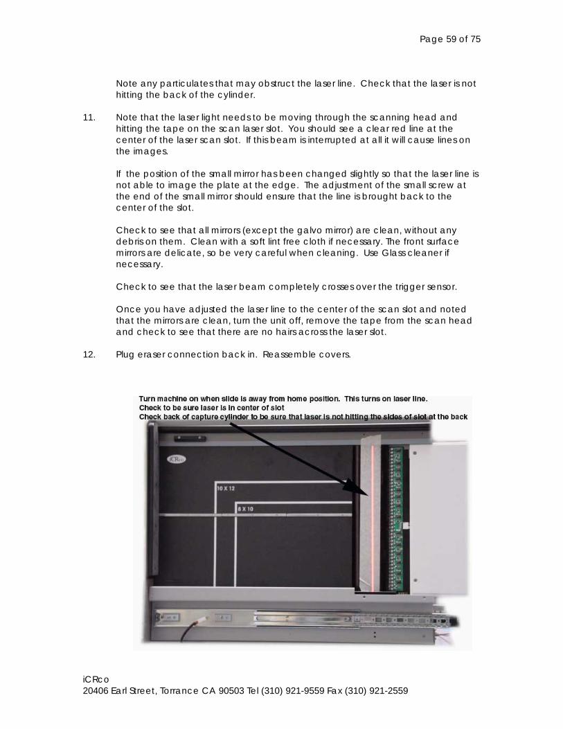
Page 59 of 75
iCRco 20406 Earl Street, Torrance CA 90503 Tel (310) 921-9559 Fax (310) 921-2559
Note any particulates that may obstruct the laser line. Check that the laser is not hitting the back of the cylinder.
11. Note that the laser light needs to be moving through the scanning head and
hitting the tape on the scan laser slot. You should see a clear red line at the center of the laser scan slot. If this beam is interrupted at all it will cause lines on the images. If the position of the small mirror has been changed slightly so that the laser line is not able to image the plate at the edge. The adjustment of the small screw at the end of the small mirror should ensure that the line is brought back to the center of the slot. Check to see that all mirrors (except the galvo mirror) are clean, without any debris on them. Clean with a soft lint free cloth if necessary. The front surface mirrors are delicate, so be very careful when cleaning. Use Glass cleaner if necessary.
Check to see that the laser beam completely crosses over the trigger sensor. Once you have adjusted the laser line to the center of the scan slot and noted that the mirrors are clean, turn the unit off, remove the tape from the scan head and check to see that there are no hairs across the laser slot.
12. Plug eraser connection back in. Reassemble covers.
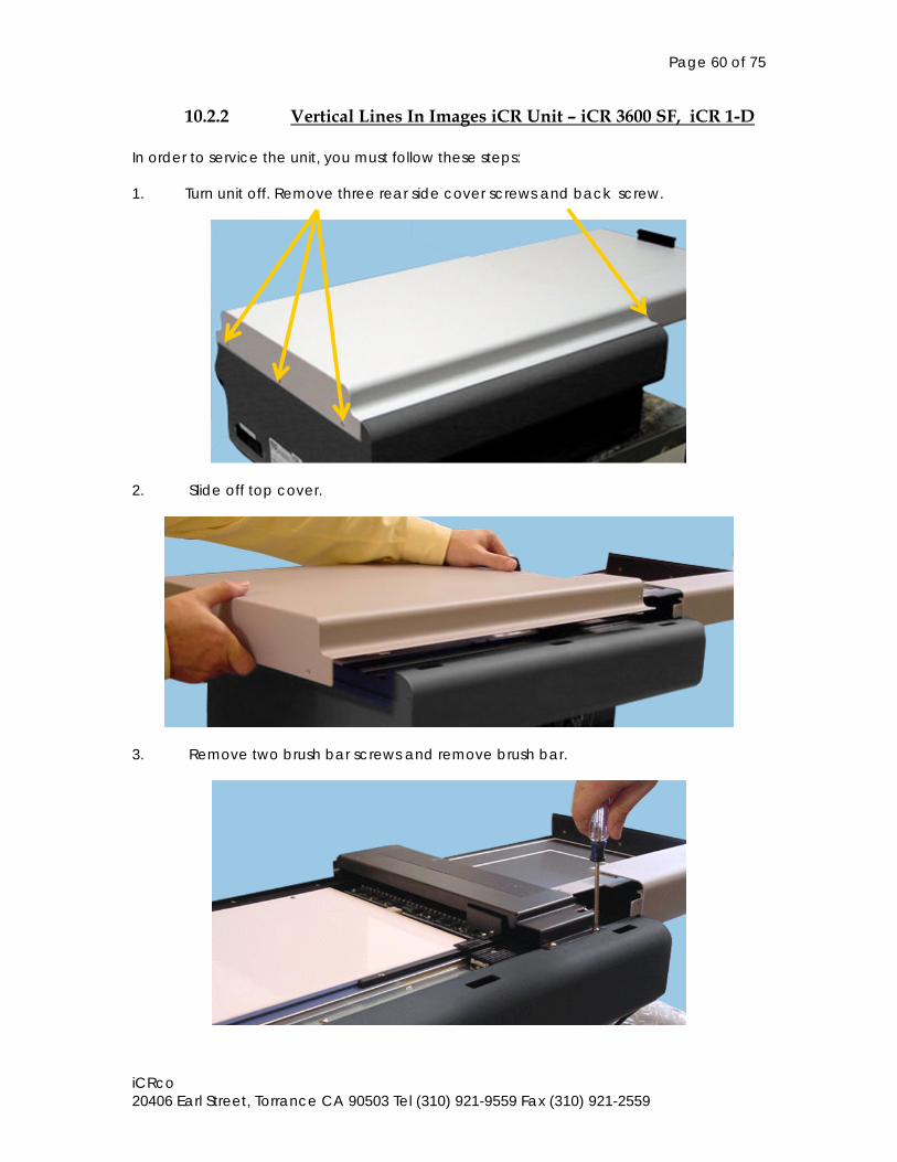
Page 60 of 75
iCRco 20406 Earl Street, Torrance CA 90503 Tel (310) 921-9559 Fax (310) 921-2559
10.2.2 Vertical Lines In Images iCR Unit – iCR 3600 SF, iCR 1-D
In order to service the unit, you must follow these steps: 1. Turn unit off. Remove three rear side cover screws and back screw.
2. Slide off top cover.
3. Remove two brush bar screws and remove brush bar.
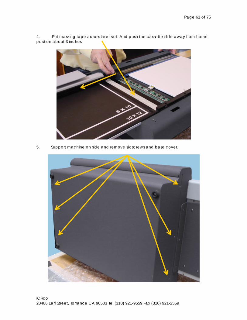
Page 61 of 75
iCRco 20406 Earl Street, Torrance CA 90503 Tel (310) 921-9559 Fax (310) 921-2559
4. Put masking tape across laser slot. And push the cassette slide away from home position about 3 inches.
5. Support machine on side and remove six screws and base cover.
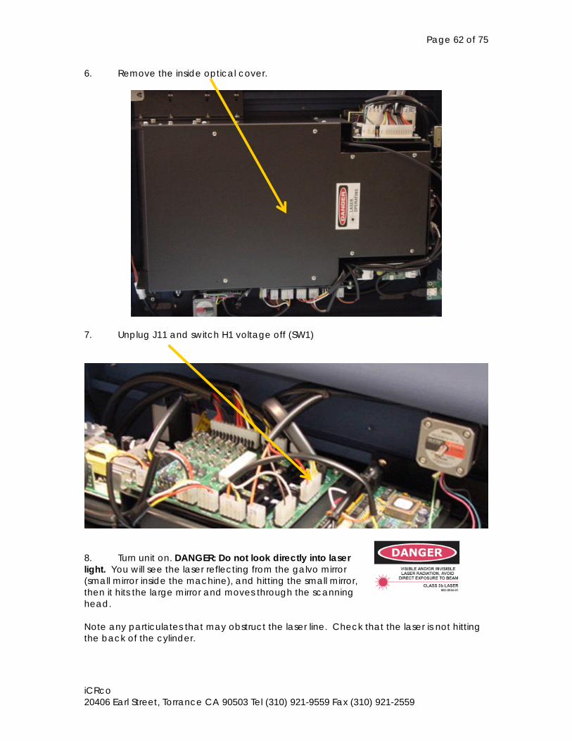
Page 62 of 75
iCRco 20406 Earl Street, Torrance CA 90503 Tel (310) 921-9559 Fax (310) 921-2559
6. Remove the inside optical cover.
7. Unplug J11 and switch H1 voltage off (SW1)
8. Turn unit on. DANGER: Do not look directly into laser light. You will see the laser reflecting from the galvo mirror (small mirror inside the machine), and hitting the small mirror, then it hits the large mirror and moves through the scanning head. Note any particulates that may obstruct the laser line. Check that the laser is not hitting the back of the cylinder.
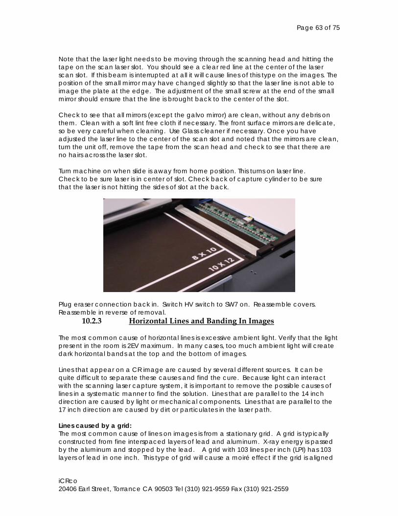
Page 63 of 75
iCRco 20406 Earl Street, Torrance CA 90503 Tel (310) 921-9559 Fax (310) 921-2559
Note that the laser light needs to be moving through the scanning head and hitting the tape on the scan laser slot. You should see a clear red line at the center of the laser scan slot. If this beam is interrupted at all it will cause lines of this type on the images. The position of the small mirror may have changed slightly so that the laser line is not able to image the plate at the edge. The adjustment of the small screw at the end of the small mirror should ensure that the line is brought back to the center of the slot. Check to see that all mirrors (except the galvo mirror) are clean, without any debris on them. Clean with a soft lint free cloth if necessary. The front surface mirrors are delicate, so be very careful when cleaning. Use Glass cleaner if necessary. Once you have adjusted the laser line to the center of the scan slot and noted that the mirrors are clean, turn the unit off, remove the tape from the scan head and check to see that there are no hairs across the laser slot.
Turn machine on when slide is away from home position. This turns on laser line. Check to be sure laser is in center of slot. Check back of capture cylinder to be sure that the laser is not hitting the sides of slot at the back.
Plug eraser connection back in. Switch HV switch to SW7 on. Reassemble covers. Reassemble in reverse of removal.
10.2.3 Horizontal Lines and Banding In Images The most common cause of horizontal lines is excessive ambient light. Verify that the light present in the room is 2EV maximum. In many cases, too much ambient light will create dark horizontal bands at the top and the bottom of images. Lines that appear on a CR image are caused by several different sources. It can be quite difficult to separate these causes and find the cure. Because light can interact with the scanning laser capture system, it is important to remove the possible causes of lines in a systematic manner to find the solution. Lines that are parallel to the 14 inch direction are caused by light or mechanical components. Lines that are parallel to the 17 inch direction are caused by dirt or particulates in the laser path. Lines caused by a grid: The most common cause of lines on images is from a stationary grid. A grid is typically constructed from fine interspaced layers of lead and aluminum. X-ray energy is passed by the aluminum and stopped by the lead. A grid with 103 lines per inch (LPI) has 103 layers of lead in one inch. This type of grid will cause a moiré effect if the grid is aligned

Page 64 of 75
iCRco 20406 Earl Street, Torrance CA 90503 Tel (310) 921-9559 Fax (310) 921-2559
with the fast scan direction on the plate. The fast scan is across the 14 inch of a 14X17 inch cassette. Lines will change as the image is zoomed up and down. Solution: Change the grid to a 178 lines per inch grid, or rotate the cassette under the grid so that the grid lines are perpendicular to the fast scan (14 inch) direction. Take a table top test image (Without a grid) to check to see if the lines are not present. Lines caused by light: A common cause of lines across the 14 inch length is light incursion. These lines are typically seen at the ends of the cassette. (Top and Bottom of the 17 inch length). If the door is left open during a scan these lines will appear as the cassette enters the scan region and leaves it. Another cause can be a light leak in the eraser cover. Lines are quite strong in this case, and they can even ruin the diagnostic quality of the images. Solution: Lines caused by light can be controlled in several ways. As an experiment, turn all the lights off in the room, or cover the machine with a black cloth. Scan a test image, and check to see if the lines are still apparent. If the lines are still present, with no change, then the lights in the room are not the cause. If the lines disappear, then the eraser cover is to blame. Check for light leaks by scanning a plate and looking for signs of red light leaking from the eraser cover. Reduce the light levels in the scan room or repair the eraser cover. (A strip of black plastic can be inserted into the cover at the gap to ensure that the cover is light tight.
Page 65 of 75
iCRco 20406 Earl Street, Torrance CA 90503 Tel (310) 921-9559 Fax (310) 921-2559
Lines caused by Over Exposure: Lines can be created when low level background noise is amplified by over exposure. Because CR images do not become darker with higher exposure, a common mistake is to increase the dose too much. The CR is typically compared to a 200 speed system so one should use Extremity techniques to get proper exposures. If a 400 speed setting is used images will still be diagnostic, but they may have more quantum mottle and the window and level will be more difficult to find. CR imaging is only approximately the same as a 200 speed film system, it is possible to reach a 300-400 speed equivalent on some shots. Solution: Expose a test image at a standard exposure and note the presence of lines. Reduce the exposure and see if the lines are no longer present. Lines caused by bad power: The CR unit will be very susceptible to surrounding electronic noise. If the power source is not stable, this could cause line artifacts in the image. Please be sure to use a UPS (Uninterruptible Power Supply) of at least 670VA. It is possible to drive noise into the system with a bad network cable. This noise is more likely to be wavy lines. Solution: Check to be sure that the UPS is connected properly, unplug internet connection and scan to check for lines. Lines caused by dirt/dust/particulates: The optical components in the iCR1000 and iCR2600 are vertically mounted to greatly reduce the chance that dust or dirt will settle on the mirror surfaces in the machine. A line parallel to the 17 inch axis, all through the image is caused by dust or particulates in the scan path. If the line is sharp, then it is located at the front of the scan head. If the line is blurred across several pixels then it is caused by particulates on the mirror surfaces. Solution: For sharp lines: Remove the front covers of the unit, clean the front surface of the scan head. (Follow the service manual procedure). NOTE: This process should not be attempted by the end user. Trained technicians only should attempt this process. WARNING: Red laser light is emitted from the front of the scan head. DO NOT TURN THE MACHINE ON WITH THE COVERS REMOVED. For blurred lines: Remove the back of the machine, remove the optical cover as per the service manual. Clean the front surface mirrors (Large and Small). Do not clean the galvo mirror. Use alcohol and a lint free cloth. Do not rub mirror surfaces.
Page 66 of 75
iCRco 20406 Earl Street, Torrance CA 90503 Tel (310) 921-9559 Fax (310) 921-2559
Lines Caused by Bad Cable: Electrical noise from the computer or CR can be driven into the system if there is a bad cable that is improperly grounded. This will cause lines parallel to the 14 inch axis. Solution: Cable can simply be unplugged or not properly plugged into the computer. Be sure that the cable is properly plugged into the computer. (Check for bent pins). With the machine turned on and a 14X17 cassette in place, go into the Admin screen in the scanner interface. (Click on Admin, type in the password: earl ). Click on FOCUS This will move the scanner forward and a line will appear on a white grid. This line should be stable and straight. If there are bumps or waves in the line, light or electrical noise is being fed into the system. While this screen is up, gently wiggle the wire in the computer to see if the line location changes. Gently Wiggle the wire near the connector in the back of the CR Any change in the signal on the screen will indicate if the cable is bad. Cable housing on the computer side can be taken apart and checked for conductivity and proper grounding. CHECK FOR BENT PINS. Replace Cable. Lines caused by improper insertion of the DAQ card: DAQ card is located in the computer. If due to shipping or on-site installation the card is not properly inserted, lines can appear on the image. (This may also cause intermittent failure of the scan process). Solution: Reinsert the DAQ card into the PC. Ensure that it is properly held in place, and be sure that it does not come out of the socket when the cable is plugged into it. Lines caused by improper alignment of the motor gear and slide: Horizontal lines can be caused by the improper alignment of the motor and slide. Although unlikely, it is possible that the motor or slide alignment can change in shipping or handling of the machine. The slide is the black part that the cassette is placed into. The location of the slide is determined by the cassette. It should not be changed. It is easy to check the alignment of the slide. If it is not aligned the cover of the cassette will bump or fall off the machine when the cassette is returned to home. Solution: Scan a cassette, listen for noises or in a semi-dark room, open the CR door and watch the cassette as it is scanned. If the cover moves at all, the alignment of the slide is wrong. If it is necessary to relocate the slide, remove all the covers as per the service manual, carefully slide the slide clip (Black) into the eraser cover. Loosen the screws that hold the Accuride slide to the case. (Screws should still be snug enough so that the slide does not move easily). Return the clip so that the both ends of the Accuride slide are visible and place a cassette on the clip. Adjust the slide/clip so that the cassette sits properly on the metal strips on the scan plate, tighten the end screws of the slide to hold it in position. Check that the position is correct by scanning a plate. NOTE: Be sure that the brush bar is on the unit. Scan in a dark room.
Page 67 of 75
iCRco 20406 Earl Street, Torrance CA 90503 Tel (310) 921-9559 Fax (310) 921-2559
Solution: If the slide is in the proper position (it should be), then the motor adjustment could be off. In the field an approximation of the pitch adjustment can be done in the following manner:
(1) Remove the back cover of the CR unit. (2) Remove the eraser cover from the CR unit. (3) Locate the motor assembly. It is on the bottom left hand side of the unit.
There are two screws with star nuts holding the motor in place. There is a yellow damper on the back of the motor assembly.
(4) With the CR unit off, rotate the yellow damper so that the slide/clip moves into the location of the eraser cover. Note the movement of the clip/slide and be sure that it is moving away from the home position into the eraser cover. It is moving to the left as you face the back of the machine.
NOTE: Do not force the rotation of the motor. If the motor is rotated in the wrong direction, the slide will hit the side of the case and the motor will stop rotating. It is possible to damage the gear assembly if this rotation is forced. (5) When the slide/clip is far enough out, you will see the slide gear on the underside of the slide/clip assembly.
(5) Place a 3” length of clear tape (3M desk tape) over the gear. Turn the motor/slide in the opposite direction until you are sure that the tape is between the flat gear and the pinion gear.
(6) Loosen the star nuts that hold the motor in place. To do this you will need a nut driver with a 5/16th inch long throat socket driver. The screws are long so the nut driver needs to have a hollow shaft or if you are using a socket driver, a long socket is needed.
(7) Press the motor assembly up into the gear. Be sure that pressure is forcing the pinion gear into the rack gear.
(8) Tighten the screws that hold the motor, being careful not to reduce the pressure on the motor assembly.
(9) Roll the slide/clip until you can remove the tape from the rack gear. Test the unit to see if the line pattern is gone.
10.2.4 System Will Not Detect Phosphor Screens If the laser fails or does not cross the jitter sensor the plate will travel for 3-4 seconds and then return to the home position with an error message “No Data Found”. To determine if the laser is functioning, remove the main enclosure, turn the laser on and visually determine if the laser is functioning. Ensure that the interior of the scanner is not exposed to ambient light, as this might damage the Photo-Multiplier Tubes.
10.2.5 No Galvanometer Movement If there is no Galvo movement troubleshooting should start with checking the –15/+15V circuits on the power distribution board by pressing down the 2 test buttons on the board. If one or both yellow lights are not lighting up it means that one or both of the fuses have blown and that the driving power is interrupted and needs to be checked. Proceed by checking all connection wires that concern the Galvo/Galvo controller. Another source of this problem could be the Sequence Controller.
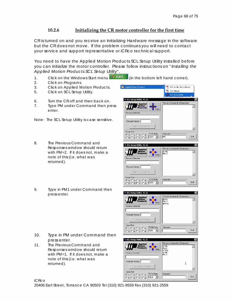
Page 68 of 75
iCRco 20406 Earl Street, Torrance CA 90503 Tel (310) 921-9559 Fax (310) 921-2559
10.2.6 Initializing the CR motor controller for the first time CR is turned on and you receive an Initializing Hardware message in the software but the CR does not move. If the problem continues you will need to contact your service and support representative or iCRco technical support. You need to have the Applied Motion Products SCL Setup Utility installed before you can initialize the motor controller. Please follow instructions on “Installing the Applied Motion Products SCL Setup Utility”. 1. Click on the Windows Start menu (in the bottom left hand corner). 2. Click on Programs. 3. Click on Applied Motion Products. 5. Click on SCL Setup Utility.
6. Turn the CR off and then back on. 7. Type PM under Command then press
enter. Note: The SCL Setup Utility is case sensitive. 8. The Previous Command and Responses window should return with PM=2. If it does not, make a note of this (i.e. what was returned).
9. Type in PM1 under Command then press enter.
10. Type in PM under Command then
press enter. 11. The Previous Command and Responses window should return with PM=1. If it does not, make a note of this (i.e. what was returned).
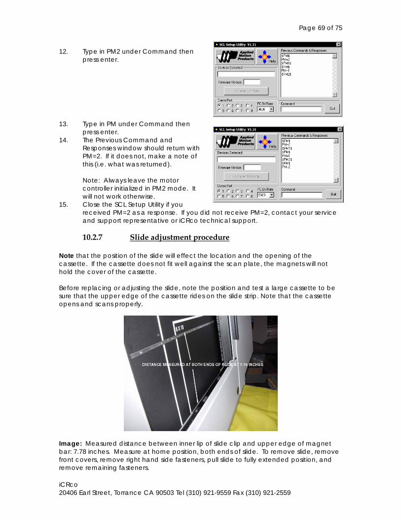
Page 69 of 75
iCRco 20406 Earl Street, Torrance CA 90503 Tel (310) 921-9559 Fax (310) 921-2559
12. Type in PM2 under Command then press enter.
13. Type in PM under Command then
press enter. 14. The Previous Command and
Responses window should return with PM=2. If it does not, make a note of this (i.e. what was returned).
Note: Always leave the motor controller initialized in PM2 mode. It will not work otherwise.
15. Close the SCL Setup Utility if you received PM=2 as a response. If you did not receive PM=2, contact your service and support representative or iCRco technical support.
10.2.7 Slide adjustment procedure
Note that the position of the slide will effect the location and the opening of the cassette. If the cassette does not fit well against the scan plate, the magnets will not hold the cover of the cassette. Before replacing or adjusting the slide, note the position and test a large cassette to be sure that the upper edge of the cassette rides on the slide strip. Note that the cassette opens and scans properly.
Image: Measured distance between inner lip of slide clip and upper edge of magnet bar: 7.78 inches. Measure at home position, both ends of slide. To remove slide, remove front covers, remove right hand side fasteners, pull slide to fully extended position, and remove remaining fasteners.
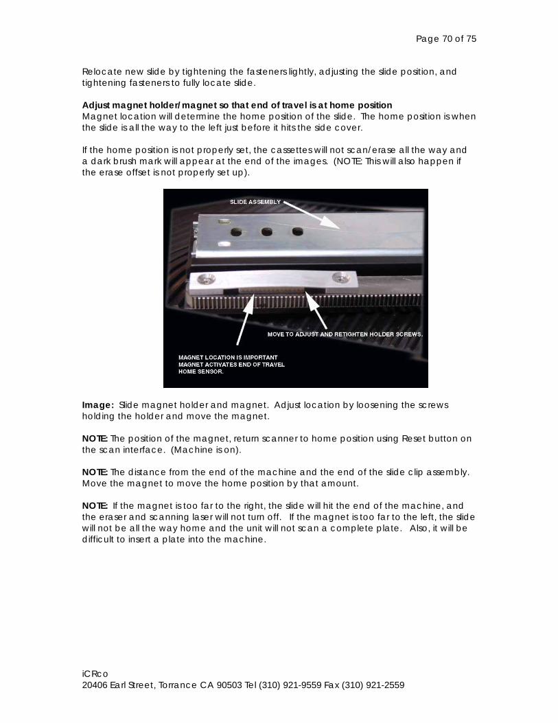
Page 70 of 75
iCRco 20406 Earl Street, Torrance CA 90503 Tel (310) 921-9559 Fax (310) 921-2559
Relocate new slide by tightening the fasteners lightly, adjusting the slide position, and tightening fasteners to fully locate slide. Adjust magnet holder/magnet so that end of travel is at home position Magnet location will determine the home position of the slide. The home position is when the slide is all the way to the left just before it hits the side cover. If the home position is not properly set, the cassettes will not scan/erase all the way and a dark brush mark will appear at the end of the images. (NOTE: This will also happen if the erase offset is not properly set up).
Image: Slide magnet holder and magnet. Adjust location by loosening the screws holding the holder and move the magnet. NOTE: The position of the magnet, return scanner to home position using Reset button on the scan interface. (Machine is on). NOTE: The distance from the end of the machine and the end of the slide clip assembly. Move the magnet to move the home position by that amount. NOTE: If the magnet is too far to the right, the slide will hit the end of the machine, and the eraser and scanning laser will not turn off. If the magnet is too far to the left, the slide will not be all the way home and the unit will not scan a complete plate. Also, it will be difficult to insert a plate into the machine.
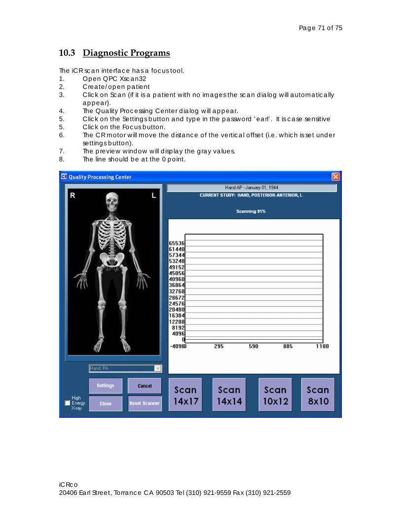
Page 71 of 75
iCRco 20406 Earl Street, Torrance CA 90503 Tel (310) 921-9559 Fax (310) 921-2559
10.3 Diagnostic Programs The iCR scan interface has a focus tool. 1. Open QPC Xscan32 2. Create/open patient 3. Click on Scan (if it is a patient with no images the scan dialog will automatically
appear). 4. The Quality Processing Center dialog will appear. 5. Click on the Settings button and type in the password ‘earl’. It is case sensitive 5. Click on the Focus button. 6. The CR motor will move the distance of the vertical offset (i.e. which is set under
settings button). 7. The preview window will display the gray values. 8. The line should be at the 0 point.
Page 72 of 75
iCRco 20406 Earl Street, Torrance CA 90503 Tel (310) 921-9559 Fax (310) 921-2559
11.0 REPLACEMENT PARTS 11.1 Removing the iCR Back Cover 1. Use a #2 Phillips head screwdriver to remove the screws.
11.1.1 Main Enclosure Removal The optical cover is held on by 6 screws and sealed from light with black phototape.
11.1.2 Front Cover Removal The front cover is held on by 7 6-32 screws on the left side and the top of the iCR and 2 10-32 screws on the upper right hand corner at the front of the unit. 11.2 Field Modules This section discusses the sub-systems and components in the iCR digitizer that can be replaced in the field. These are called Field Replaceable Modules. Certain FRM’s may require some adjustments when they are replaced. The following chart details all of the FRM’s in the READER that have adjustment requirements when they are replaced. All adjustments are contained in Section 5 of the Service Manual. Sub-Assembly Adjustments: 1. Optics PMT Amp 2. PMT Tubes PMT 3. Laser Optical, PMT 4. Galvo PCA Linearity 5. Galvo Motor Linearity 6. Electronics 7. Power Supply 11.3 Optics Module Inside the system, there are five components that can be replaced in the field. These are: 1. PMT tubes 2. PMT amplifier board 3. Laser 4. Galvonometer boards 5. Galvo Motor
Page 73 of 75
iCRco 20406 Earl Street, Torrance CA 90503 Tel (310) 921-9559 Fax (310) 921-2559
11.3.1 PMT Sub-System The PMT sub-system (the PMT Tubes and PMT BOARD) can be replaced by following the procedure outline below 1. Remove 4 screws that hold down the PMT amp. 2. Remove Amp from PMTs by lifting the board and pushing down on the PMTs at
the same time. 3. Disconnect HV, Power and signal cable. 4. The PMTs are free to be removed from the unit.
11.3.2 Laser Diode Driver Assembly Removal and Replacement WARNING USE PROPER ESD PRACTICE WHEN TOUCHING LASER OR SCANNER EXTREME CAUTION 1. The laser assembly produces 18 to 35 mW of power. Care must be taken to avoid
looking directly at the beam. 2. The laser diode output is transmitted to the lens through a fiber optic cable. The end of this cable has a protective cap that is removed when the cable is screwed into the lens assembly. Great care must be taken so that the end of the cable does not come into contact with anything, i.e., fingers, metal, etc., or damage will occur. 11.4 Removing Laser Diode Module The module is held on to the optical assembly by 4 6-32 screws. It is replaceable after taking those screws out. 11.5 Focusing the Laser Focusing the laser beam is never done as part of a standard PM. The beam spot is set at the factory and will not change without a preceding event such as changing the laser itself. Gain, laser power and cleanliness could all effect resolution quality. Never refocus the laser without consulting a member of the ICRCO Technical Support Staff. 11.6 Galvanometer Removal 1. Turn power off. 2. Remove frontcover, black scan plate and galvo cover. 3. Loosen the 4 screws that hold the galvo. 4. Disconnect power and driver cable. 5. Use the special Galvo tool provided by iCRco, to rotate the Galvo out of its
socket. 6. Since Galvo and Galvo driver board are paired up, both have to be changed
out. Galvo Replacement Procedure: Reinstall the new Galvo motor in the reverse order except do not replace the mirror until the other components are in place.
Page 74 of 75
iCRco 20406 Earl Street, Torrance CA 90503 Tel (310) 921-9559 Fax (310) 921-2559
11.7 Drive Motor Assembly Removal: 1. Remove front cover, back cover, light bar and slide. 2. Disconnect wires from motor controller. 3. Unscrew 2 mounting screws located in the upper right hand corner on the front of
the unit, just above the silver Accuride slide. 4. Hold on to the motor while unscrewing, then take it out. Replacement: The Drive Motor Assembly should be replace in the reverse order that it was removed.
Page 75 of 75
iCRco 20406 Earl Street, Torrance CA 90503 Tel (310) 921-9559 Fax (310) 921-2559
12.0 SCHEMATICS AND DRAWINGS PART NUMBER DESCRIPTION _____________________ __________________________ 0070-578 TREE, PRODUCT, LS135 0071-317 DIAG, AC & DC WIRING, LS135 0071-318 DIAG, SYSTEM INTCON & PWR DISTRIBUTION, LS135 0070-679 SCH, REF LED, SCRN PRES1, V2 0070-235 SCH, DCB3, V1, LSDT 0068-855 SCHEMATIC, GALVO DRIVER V5, LSDT 0071-552 SCH, BLUE LED/ISFILM, LS135 0070-254 SCH, PMT PREAMP, V1, LSDT 0071-997 SCH, DATA ACQUISITION BOARD 4, V1, LS135B