Icon LCD Keypad V1.0 Reference & Installation Manual WinLoad instructions or visit our website at ....
24
Icon LCD Keypad V1.0 Reference & Installation Manual DGP2-640
Transcript of Icon LCD Keypad V1.0 Reference & Installation Manual WinLoad instructions or visit our website at ....

DGP2640_EI00.fm Page -3 Thursday, April 7, 2005 12:05 PM
Icon LCD Keypad V1.0
Reference & Installation Manual
DGP2-640
DGP-641

DGP2640_EI00.fm Page -2 Thursday, April 7, 2005 12:05 PM

DGP2640_EI00.fm Page -1 Thursday, April 7, 2005 12:05 PM
Table of Contents
Introduction...................................................................1Specifications ........................................................................ 1
Installation.....................................................................2Connecting the Keypad......................................................... 2Connecting the Keypad Zone................................................ 2Programmable Output........................................................... 3
Programming ................................................................4Entering Module Programming Mode ................................... 4Programming Methods.......................................................... 5Module Broadcast ................................................................. 5
System Options ............................................................7Partition Display) ................................................................... 7Confidential Mode ................................................................. 8Exit Confidential Mode .......................................................... 8Muting ................................................................................... 8Beep on Exit Delay................................................................ 9Chime on Zone Closure ........................................................ 9Time Format.......................................................................... 9Beep on Trouble.................................................................... 9Keypad Anti-Tamper Enable ............................................... 10Confidential Mode Timer ..................................................... 11
Programmable Output Options .................................11PGM State........................................................................... 11PGM Deactivation Mode ..................................................... 11PGM Base Time.................................................................. 12PGM Timer.......................................................................... 12

DGP2640_EI00.fm Page 0 Thursday, April 7, 2005 12:05 PM
PGM Activation ................................................................... 12PGM Deactivation ............................................................... 13PGM Test............................................................................ 13
List of Sections .......................................................... 14

DGP2640_EI00.fm Page 1 Thursday, April 7, 2005 12:05 PM
1.0 IntroductionThank you for choosing Paradox Security Systems. Our advanced technology security systems provide you with reliable security protection and powerful features which are easy to use. The DGP2-640 Icon LCD keypad provides easy access to the security system’s functions and status at a glance.
1.1 SpecificationsPower input: 12-16 Vdc, 80mA maximumPGM current limit: 50mANumber of inputs: 1Number of zones: 1 standard zone, no tamper recognitionLocate deactivation: Anti-tamper switchCompatibility: Any Digiplex control panel
Table 1: LED FunctionalitiesLED Function Display Status
AC Light ONOFF
Power OnPower Off
Status Light Green ON All zones closedGreen OFF Zone(s) openGreen flash Exit delayRed ON Area(s) armedRed OFF Area(s) disarmedRed flash System in alarmGreen and yellow flash simultaneously
Locate indication
Red and yellow flash alternately
Combus fault
DGP2-640 Icon LCD Keypad 1
DGP2640_EI00.fm Page 2 Thursday, April 7, 2005 12:05 PM
2.0 Installation
2.1 Connecting the KeypadThe DGP2-640 is connected to the control panel’s combus in a star and/or daisy chain configuration. The four-wire combus provides power and two-way communication between the control panel and all modules connected to it. Connect the four terminals labeled +, -, GRN and YEL on the keypad to the corresponding terminals on the control panel as shown in Figure 1 on page 3. Refer to the control panel’s Reference & Installation Manual for the maximum allowable installation distance from the control panel.
2.2 Connecting the Keypad ZoneYour keypad has one hardwired input terminal, allowing you to connect one detector or door contact directly to it. For example, you can wire a door contact located at the entry point of an establishment directly to the input terminal of the entry point keypad, instead of wiring the door contact all the way to the control panel.
Connect the device to the keypad's input terminal as shown in Figure 1 on page 3.
The keypad zone follows the control panel’s EOL definition.
In order to communicate its status to the control panel, the keypad's input must be assigned to a zone in the control panel and the zone's parameters must be defined.
The control panel does not recognize tampers originating from the keypad zone.
For more information on zone assignment, please refer to your control panel's Reference & Installation Manual. Please note that even with the ATZ (zone doubling) feature enabled, the keypad
2 Reference & Installation Manual
DGP2640_EI00.fm Page 3 Thursday, April 7, 2005 12:05 PM
supports only one detection device.
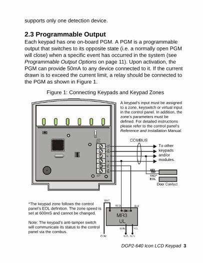
2.3 Programmable OutputEach keypad has one on-board PGM. A PGM is a programmable output that switches to its opposite state (i.e. a normally open PGM will close) when a specific event has occurred in the system (see Programmable Output Options on page 11). Upon activation, the PGM can provide 50mA to any device connected to it. If the current drawn is to exceed the current limit, a relay should be connected to the PGM as shown in Figure 1.
Figure 1: Connecting Keypads and Keypad Zones
A keypad’s input must be assigned to a zone, keyswitch or virtual input in the control panel. In addition, the zone’s parameters must be defined. For detailed instructions please refer to the control panel’s Reference and Installation Manual.
*The keypad zone follows the control panel’s EOL definition. The zone speed is set at 600mS and cannot be changed.
Note: The keypad’s anti-tamper switch will communicate its status to the control panel via the combus.
To other keypads and/or modules.
DGP2-640 Icon LCD Keypad 3

DGP2640_EI00.fm Page 4 Thursday, April 7, 2005 12:05 PM
3.0 ProgrammingTo program the DGP2-640 keypad, enter Module Programming Mode and then enter the desired section followed by the required data. When programming the keypad, use the keypad’s programming sheets (found in the Digiplex Modules’ Programming Guide; also, refer to List of Sections on page 14) to keep track of which sections were programmed and how. We strongly recommend you read this entire manual before you begin programming.
The Icon keypad can also be programmed using the WinLoad Installer Upload/Download Software. You can program control panels and keypads remotely through a modem at 300 baud or on-site at 19.2k/38.4k baud with a 306 Adapter. For more information, refer to the WinLoad instructions or visit our website at www.paradox.ca.
3.1 Entering Module Programming ModeThe keypad, like all other modules in the system, is programmed through the control panel. To do so, you must first enter Module Programming Mode:
1. From Normal Mode press and hold the [0] key.2. Enter the [INSTALLER CODE] (by default 000000).3. Enter section [953] (DGP-848) / [4003] (DGP-NE96).4. Enter the keypad’s 8-digit [SERIAL NUMBER].5. Enter the 3-digit [SECTION] you want to program.6. Enter the required [DATA].
The control panel will then redirect all programming to the selected keypad. Every time the key is pressed it will revert to the preceding step—unless entering in data, in which case it will erase the current data entry. Please note that the serial number is located on the keypad's PC board or enter section [000] (DGP-848) or
4 Reference & Installation Manual

DGP2640_EI00.fm Page 5 Thursday, April 7, 2005 12:05 PM
[0000] (DGP-NE96) in Step 3 to view the keypad’s serial number. When entering the serial number, the and icons on the right side of the screen will illuminate and you can use the [ ] and [ ] keys to scroll through the serial number.
3.2 Programming MethodsThe following methods can be used when programming the keypad:
3.2.1 Feature Select ProgrammingSome sections are programmed by enabling or disabling options. Within the sections, numbers from [1] to [8] represent a specific keypad option. Press the key corresponding to the desired option and the digit will appear in the display. This means the option is enabled. Press the key again to remove the digit from the display thereby disabling the option. Press the key when options are set.
3.2.2 Decimal ProgrammingSome sections require that a decimal value be entered. In this method, any digit from 000 to 255 can be entered.
3.3 Module BroadcastThe control panel’s Module Broadcast feature can be used to copy the contents of one keypad to one or more keypads.
1. From Normal Mode press and hold the [0] key.2. Enter the [INSTALLER CODE] (default: 000000).3. Enter section [954] (DGP-848) / [4004] (DGP-NE96).4. Enter the [SERIAL #] of the source keypad. The source is the
programmed keypad whose data you want to copy to other keypads. When entering the serial number, the and icons on the right side of the screen will illuminate and you can use the [ ] and [ ] keys to scroll through the serial number.
5. Enter the [SERIAL #] of the destination keypad(s). The
DGP2-640 Icon LCD Keypad 5

DGP2640_EI00.fm Page 6 Thursday, April 7, 2005 12:05 PM
destination is the keypad(s) you want to program with the source’s data. If you want to program more than one keypad with the source’s data, enter the serial numbers of the keypads one at a time.
6. Once you have entered the serial numbers of the keypad(s) you want to program, press the key.
For more information, please see the control panel’s Programming Guide.
6 Reference & Installation Manual
DGP2640_EI00.fm Page 7 Thursday, April 7, 2005 12:05 PM
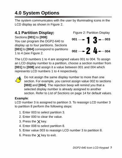
4.0 System OptionsThe system communicates with the user by illuminating icons in the LCD display as shown in Figure 2.
4.1 Partition Display)Sections [001] to [008] You can program the DGP2-640 to display up to four partitions. Sections [001] to [004] correspond to partitions 1 to 4 (see Figure 2.
The LCD numbers 1 to 4 are assigned values 001 to 004. To assign an LCD display number to a partition, choose a section number from [001] to [008] and assign it a value between 001 and 004 which represents LCD numbers 1 to 4 respectively.
Do not assign the same display number to more than one section. For example, you cannot assign value 002 to sections [003] and [004]. The rejection beep will remind you that a selected display number is already assigned to another section. Refer to List of Sections on page 14 for default values.
Example:LCD number 3 is assigned to partition 3. To reassign LCD number 3 to partition 8 perform the following steps:
1. Enter 003 to select partition 3.2. Enter 000 to clear the value.3. Press the key.4. Enter 008 to select partition 8.5. Enter value 003 to reassign LCD number 3 to partition 8.6. Press the key to exit.
004
003
002
001
Figure 2: Partition Display
DGP2-640 Icon LCD Keypad 7

DGP2640_EI00.fm Page 8 Thursday, April 7, 2005 12:05 PM
4.2 Confidential ModeSection [009]: Option [1]The keypad will switch to Confidential Mode after a period of inactivity (default is 120s) if option [1] is enabled. In Confidential Mode all LEDs will turn off until either a button is pressed or an access code is entered (see Exit Confidential Mode on page 8). Once the keypad is activated, all applicable LEDs will illuminate. To change the timer setting, see Confidential Mode Timer on page 11.
Option [1] OFF = Disabled (default)Option [1] ON = Enabled
4.3 Exit Confidential ModeSection [009]: Option [2]If confidential mode is enabled, option [2] determines how the keypad will return to normal mode after the keypad has switched to confidential mode (see Confidential Mode on page 8).
Option [2] OFF = Exit Confidential Mode by entering an access code (default)Option [2] ON = Exit Confidential Mode by pressing a button
Option [2] must be set to OFF on UL listed systems.Option [2] will only work if option [1] is enabled.
4.4 MutingSection [009]: Option [3]You can program the keypad to not emit audible sounds, including Chimed zones. During Muting, the keypad will only emit the confirmation or rejection beep and beep when users press a button.
Option [3] OFF = Audible sounds (default)Option [3] ON = Mute
8 Reference & Installation Manual

DGP2640_EI00.fm Page 9 Thursday, April 7, 2005 12:05 PM
4.5 Beep on Exit DelaySection [009]: Option [4]With option [4] enabled, the keypad will beep once every second during the Exit Delay Timer and during the final 10 seconds, it will beep more rapidly to provide a final warning before the partition is armed.
Option [4] OFF = Exit Delay beep disabledOption [4] ON = Exit Delay beep enabled (default)
4.6 Chime on Zone ClosureSection [009]: Option [5]During the Chime Zone time period that the user sets, the keypad can emit an intermittent beep whenever a zone with the Chime feature enabled closes (see the DGP2-640 User Guide for details on Chime Zones). If the user does not set the Chime Zone time period and this option is enabled, the Chime Zones will always beep upon closure.
Option [5] OFF = Chime on Zone Closure disabled (default)Option [5] ON = Chime on Zone Closure enabled
4.7 Time FormatSection [009]: Option [6]The keypad comes with a time display option that can display the date as International (24Hr) or U.S. (a.m./p.m.).
Option [6] OFF = International (default)Option [6] ON = U.S. (a.m./p.m.)
4.8 Beep on TroubleSection [010]: Options [1] to [4]Potential troubles are sorted into groups. With these options enabled, the keypad will emit an intermittent beep whenever a trouble
DGP2-640 Icon LCD Keypad 9

DGP2640_EI00.fm Page 10 Thursday, April 7, 2005 12:05 PM
condition from the Trouble Groups occurs in the system. The intermittent beep will remain activated until the user enters the Trouble Display or if the trouble is resolved (see your control panel’s Reference & Installation Manual for details concerning Trouble Display). The intermittent beep will reinitialize whenever the trouble reoccurs.
System Troubles / Clock LossOption [1] OFF = Disabled (default)Option [1] ON = Enabled
Communicator TroublesOption [2] OFF = Disabled (default)Option [2] ON = Enabled
Module / Combus TroublesOption [3] OFF = Disabled (default)Option [3] ON = Enabled
Zone TroublesOption [4] OFF = Disabled (default)Option [4] ON = Enabled
4.9 Keypad Anti-Tamper EnableSection [011]: Option [5]When the option [5] is enabled and the keypad's anti-tamper switch is triggered, the keypad will send a tamper report to the control panel via the combus. For information on how the control panel will process the tamper, refer to the tamper recognition options in your control panel’s Reference and Installation Manual.
Option [5] OFF = Keypad's anti-tamper is disabled (default)Option [5] ON = Keypad's anti-tamper is enabled
10 Reference & Installation Manual

DGP2640_EI00.fm Page 11 Thursday, April 7, 2005 12:05 PM
4.10 Confidential Mode TimerSection [012]: Default = 120 seconds Section [012] determines the amount of time a keypad is inactive before the keypad enters Confidential Mode. For more information, refer to Confidential Mode on page 8. The Confidential Mode timer can be set from 005 seconds to 255 seconds.
5.0 Programmable Output Options
5.1 PGM StateSection [011]: Option [1]The keypad's on-board PGM can be set as normally open or normally closed. When an open PGM is activated, it will close the circuit to the ground and enable any devices connected to it. When a closed PGM is activated, it will open the circuit and disable any devices connected to it. When the PGM Activation Event occurs (see PGM Activation on page 12), the PGM will switch to its opposite state (i.e. open to closed or closed to open). The PGM is limited to 50mA.
Option [1] OFF = PGM is Normally Open (default)Option [1] ON = PGM is Normally Closed
5.2 PGM Deactivation ModeSection [011]: Option [2]If option [2] is enabled, the keypad's on-board PGM will be deactivated according to the PGM Timer (see PGM Timer on page 12) instead of the PGM Deactivation Event.
Option [2] OFF = Deactivation follows PGM Deactivation Event (default)Option [2] ON = PGM will deactivate according to the PGM Timer
DGP2-640 Icon LCD Keypad 11

DGP2640_EI00.fm Page 12 Thursday, April 7, 2005 12:05 PM
5.3 PGM Base TimeSection [011]: Option [3]This option determines whether the value programmed in section [013] is in minutes or seconds.
Option [3] OFF = PGM Base Time is in seconds (default)Option [3] ON = PGM Base Time is in minutes
5.4 PGM TimerSection [013]: Default = 005If the PGM Deactivation Mode is set to follow the PGM timer, the value programmed in section [013] represents how long the PGM will remain in its opposite state (see PGM State on page 11) after being activated. To program the timer, enter a 3-digit decimal value (001 to 255) in section [013]. The 3-digit value will be multiplied by the PGM Base Time of 1 second or 1 minute (see PGM Base Time on page 12).
5.5 PGM ActivationSections [014] to [017]Modules belonging to the DGP2 series are programmed using the PGM Programming table in the Digiplex Modules’ Programming Guide. The PGM Activation Event determines which event will activate the keypad's on-board PGM output. The Event Group specifies the event, the Feature Group identifies the source, and the Start # and End # set the range within the Feature Group. Use the PGM Programming Table in the Digiplex Modules’ Programming Guide to program the keypad’s PGM deactivation Event.
Enter the sections that correspond to the Event Group, Feature Group, Start # and End # of the PGM and enter the required data.
Event Group Feature Group Start # End #PGM [014] __/__/__ [015]__/__/__ [016]__/__/__ [017]__/__/__
12 Reference & Installation Manual
DGP2640_EI00.fm Page 13 Thursday, April 7, 2005 12:05 PM
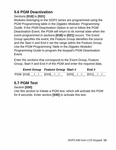
5.6 PGM Deactivation Sections [018] to [021]Modules belonging to the DGP2 series are programmed using the PGM Programming table in the Digiplex Modules’ Programming Guide. If the PGM Deactivation Option is set to follow the PGM Deactivation Event, the PGM will return to its normal state when the event programmed in sections [018] to [021] occurs. The Event Group specifies the event, the Feature Group identifies the source and the Start # and End # set the range within the Feature Group. Use the PGM Programming Table in the Digiplex Modules’ Programming Guide to program the keypad’s PGM Deactivation Event.
Enter the sections that correspond to the Event Group, Feature Group, Start # and End # of the PGM and enter the required data.
5.7 PGM TestSection [030] Use this section to initiate a PGM test, which will activate the PGM for 8 seconds. Enter section [030] to activate this test.
Event Group Feature Group Start # End #PGM [018] __/__/__ [019]__/__/__ [020]__/__/__ [021]__/__/__
DGP2-640 Icon LCD Keypad 13

DGP2640_EI00.fm Page 14 Thursday, April 7, 2005 12:05 PM
6.0 List of Sections
* Enter the Data value 000 to disable the desired section(s).
Partitions are displayed by numerical digits that accompany the state of the system. The keypad will not allow you to assign the same display number to more than one section.
A maximum of 4 partitions can be assigned to the keypad.
Section Description Data Default[001] Partition 1 Display __/__/__ (000 to 004)* 001[002] Partition 2 Display __/__/__ (000 to 004)* 002 [003] Partition 3 Display __/__/__ (000 to 004)* 003 [004] Partition 4 Display __/__/__ (000 to 004)* 004 [005] Partition 5 Display __/__/__ (000 to 004)* 000 [006] Partition 6 Display __/__/__ (000 to 004)* 000[007] Partition 7 Display __/__/__ (000 to 004)* 000[008] Partition 8 Display __/__/__ (000 to 004)* 000
14 Reference & Installation Manual

DGP2640_EI00.fm Page 15 Thursday, April 7, 2005 12:05 PM
= Default
= Default
Section [009]: Keypad Options
Option Description OFF ON
[1] Confidential Mode Disabled Enabled[2] Exit Confidential Mode Enter Code Press key[3] Muting Disabled Enabled[4] Beep on Exit Delay Disabled Enabled[5] Chime on Zone
Closure Disabled Enabled
[6] Time Format International U.S. (a.m./p.m.)
Section [010]: Beep on Trouble
Option Description OFF ON
[1] Beep on System Troubles / Clock Loss
Disabled Enabled
[2] Beep on Communicator Troubles
Disabled Enabled
[3] Beep on Module / Combus Troubles
Disabled Enabled
[4] Beep on Zone Troubles Disabled Enabled [5] to [8] Future Use N/A N/A
DGP2-640 Icon LCD Keypad 15

DGP2640_EI00.fm Page 16 Thursday, April 7, 2005 12:05 PM
= Default
PGM Activation
PGM Deactivation
Section [011]: PGM & Keypad Tamper Options
Option Description OFF ON
[1] PGM State N.O. N.C.
[2] PGM Deactivation Mode
Deactivation Event
PGM Timer
[3] PGM Base Time Seconds Minutes
[5] Keypad Anti-Tamper Disabled Enabled
Section Data Description Default[012] __/__/__ (005-255) Confidential Mode Timer 120s
Section Data Description Default[013] __/__/__ (001-255) PGM Timer 005
Event group Feature group Start # End #PGM [014] __/__/__ [015]__/__/__ [016]__/__/__ [017]__/__/__
Event group Feature group Start # End #PGM [018] __/__/__ [019]__/__/__ [020]__/__/__ [021]__/__/__
Section Description[030] Test PGM: Activate PGM for 8 seconds to verify if the
PGM is functioning properly
16 Reference & Installation Manual

DGP2640_EI00.fm Page 17 Thursday, April 7, 2005 12:05 PM
WarrantyParadox Security Systems Ltd. (“Seller”) warrants its products to be free from defects in materials and workmanship under normal use for a period of one year. Except as specifically stated herein, all express or implied warranties whatsoever, statutory or otherwise, including without limitation, any implied warranty of merchantability and fitness for a particular purpose, are expressly excluded. Because Seller does not install or connect the products and because the products may be used in conjunction with products not manufactured by Seller, Seller cannot guarantee the performance of the security system and shall not be responsible for circumstances resulting from the product’s inability to operate. Seller obligation and liability under this warranty is expressly limited to repairing or replacing, at Seller's option, any product not meeting the specifications. Returns must include proof of purchase and be within the warranty period. In no event shall the Seller be liable to the buyer or any other person for any loss or damages whether direct or indirect or consequential or incidental, including without limitation, any damages for lost profits stolen goods, or claims by any other party, caused by defective goods or otherwise arising from the improper, incorrect or otherwise faulty installation or use of the merchandise sold.
Notwithstanding the preceding paragraph, the Seller’s maximum liability will be strictly limited to the purchase price of the defective product. Your use of this product signifies your acceptance of this warranty.
*BEWARE: Dealers, installers and/or others selling the product are not authorized to modify this warranty or make additional warranties that are binding on the Seller.
The user is cautioned that any changes or modifications not expressly approved by Paradox Security Systems could void the user’s authority to operate/use the equipment.
© 2004-2005 Paradox Security Systems Ltd. All rights reserved. Specifications may change without prior notice. One or more of the following US patents may apply: 6215399, 6111256, 5751803, 5721542, 5287111, 5119069, 5077549, 5920259, 5886632. Canadian and international patents may also apply. Digiplex is a trademark or registered trademark of Paradox Security Systems Ltd. or its affiliates in Canada, the United States and/or other countries.
DGP2-640 Icon LCD Keypad 17

DGP2640_EI00.fm Page 18 Thursday, April 7, 2005 12:05 PM

DGP2640_EI00.fm Page 19 Thursday, April 7, 2005 12:05 PM

DGP2640_EI00.fm Page 20 Thursday, April 7, 2005 12:05 PM
For technical support in Canada or the U.S., call 1-800-791-1919 for English or 1-866-912-0600 for French, Monday to Friday from 8:00 a.m. to 8:00 p.m. EST. For technical support outside Canada
and the U.S., call 00-1-450-491-7444, Monday to Friday from 8:00 a.m. to 8:00 p.m. EST. Please feel free to visit our website at
www.paradox.ca.
780 Industriel Blvd., Saint-Eustache (Quebec) J7R 5V3 CANADATel.: (450) 491-7444 Fax: (450) 491-2313
www.paradox.caPRINTED IN CANADA - 04/2005 DGP2640-EI00