ICOM IC-7800 Brochure
8
description
ICOM IC-7800 Brochure
Transcript of ICOM IC-7800 Brochure
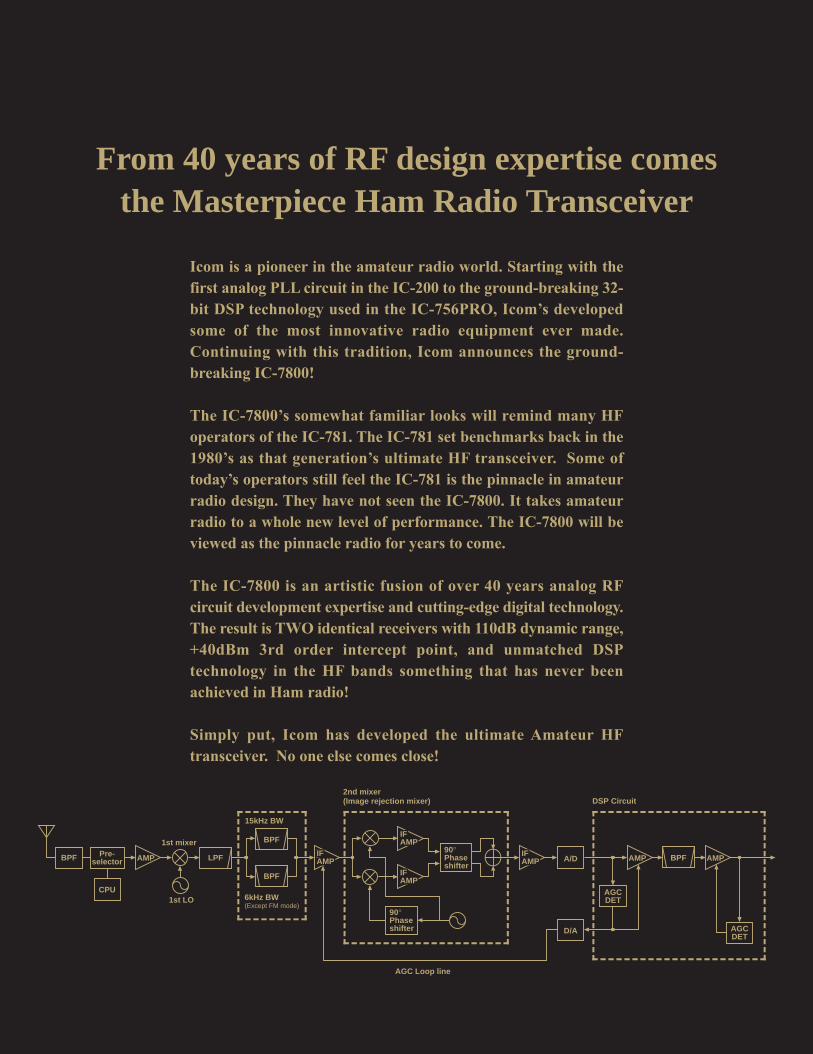
From 40 years of RF design expertise comes the Masterpiece Ham Radio Transceiver
90°Phaseshifter
90°Phaseshifter
1st mixer
1st LO 6kHz BW(Except FM mode)
15kHz BW
AGC Loop line
DSP Circuit2nd mixer(Image rejection mixer)
A/D
D/A
AGCDET
AMP AMPBPFIFAMPIFAMP
IFAMPAMPIFAMP
IFAMPIFAMP
IFAMPIFAMP
LPF
BPF
BPF
AGCDET
BPF
CPU
Pre-selector AMP
Icom is a pioneer in the amateur radio world. Starting with thefirst analog PLL circuit in the IC-200 to the ground-breaking 32-bit DSP technology used in the IC-756PRO, Icom’s developedsome of the most innovative radio equipment ever made.Continuing with this tradition, Icom announces the ground-breaking IC-7800!
The IC-7800’s somewhat familiar looks will remind many HFoperators of the IC-781. The IC-781 set benchmarks back in the1980’s as that generation’s ultimate HF transceiver. Some oftoday’s operators still feel the IC-781 is the pinnacle in amateurradio design. They have not seen the IC-7800. It takes amateurradio to a whole new level of performance. The IC-7800 will beviewed as the pinnacle radio for years to come.
The IC-7800 is an artistic fusion of over 40 years analog RFcircuit development expertise and cutting-edge digital technology.The result is TWO identical receivers with 110dB dynamic range,+40dBm 3rd order intercept point, and unmatched DSPtechnology in the HF bands something that has never beenachieved in Ham radio!
Simply put, Icom has developed the ultimate Amateur HFtransceiver. No one else comes close!
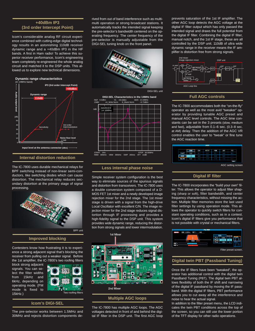
+40dBm IP3 (3rd order Intercept Point)
Icom’s considerable analog RF circuit experi-ence combined with cutting-edge digital technol-ogy results in an astonishing 110dB receiverdynamic range and a +40dBm IP3 in the HFbands. A first in Ham radio! To achieve this su-perior receiver performance, Icom’s engineeringteam completely re-engineered the whole analogcircuit and matched it to the DSP units. This al-lowed us to explore new technical dimensions.
Internal distortion reduction
The IC-7800 uses durable mechanical relays forBPF switching instead of non-linear semi-con-ductors, like switching diodes which can causedistortion. The mechanical relay reduces sec-ondary distortion at the primary stage of signalprocessing.
Improved blocking
Contesters know how frustrating it is to experi-ence a strong adjacent signal that’s blocking thereceiver from pulling out a weaker signal. Beforethe 1st amplifier, the IC-7800’s two roofing filtersblock strong adjacentsignals. You can se-lect the filter widthsfrom 15kHz and6kHz, depending onoperating mode. (FMmode is fixed to15kHz.)
Icom’s DIGI-SEL
The pre-selector works between 1.5MHz and30MHz and rejects distortion components de-
rived from out of band interference such as multi-multi operation or strong broadcast stations. Itautomatically tracks the intended signal keepingthe pre-selector’s bandwidth centered on the op-erating frequency. The center frequency of thepre-selector is manually adjustable from theDIGI-SEL tuning knob on the front panel.
Less internal phase noise
Simple receiver system configuration is the bestway to eliminate sources of the spurious signalsand distortion from transceivers. The IC-7800 usesa double conversion system composed of a D-MOS FET 1st mixer and a newly developed imagerejection mixer for the 2nd stage. The 1st mixerstage is driven with a signal from the high-driveLocal Oscillator with excellent C/N. The image re-jection mixer for the 2nd stage reduces signal dis-tortion through IF processing and provides ahigh-fidelity signal to the DSP unit. This systemprovides wide dynamic range, reducing the distor-tion from strong signals and lower intermodulation.
Multiple AGC loops
The IC-7800 has multiple AGC loops. The AGCvoltages detected in front of and behind the digi-tal IF filter in the DSP unit. The first AGC loop
prevents saturation of the 1st IF amplifier. Theother AGC loop detects the AGC voltage at thedigital IF filter output which has only passed theintended signal and draws the full potential fromthe digital IF filter. Combining the digital IF filter,manual notch, and the 1st IF stage, these are allcontrolled by the DSP unit. 110dB of ultra widedynamic range in the receiver means the IF am-plifier is distortion free from strong signals.
Full AGC controls
The IC-7800 accommodates both the “on-the-fly”operator as well as the most avid “tweaker” op-erator by providing tunable AGC preset andmanual AGC level controls. The AGC time con-stants can be set in the 3 presets (slow, mediumand fast), adjustable from 0.1–6 sec. (0.3–8 sec.at AM) delay. Then the addition of the AGC VRcontrol enables the user to “tweak” or fine tunethe AGC reaction time.
Digital IF filter
The IC-7800 incorporates the “build your own” fil-ter. This allows the operator to adjust filter shap-ing (sharp or soft), filter bandwidth, and centerfrequency characteristics, without missing the ac-tion. Multiple filter memories store the last usedfilter settings by using operation mode. This al-lows the operator to quickly switch filters for con-stant operating conditions, such as in a contest.Icom’s digital IF filters give you performance thatis not possible with crystal or mechanical filters.
Digital twin PBT (Passband Tuning)
Once the IF filters have been “tweaked”, the op-erator has additional control with the digital twinPassBand Tuning (PBT). The digital twin PBT al-lows flexibility of both the IF shift and narrowingof the digital IF passband by moving the IF pass-band. With the digital IF filters, PBT performanceallows you to cut away all the interference andnoise to hear the actual signal. In addition to the filter preset menu, the LCD indi-cates the twin PBT conditions across the top ofthe screen, so you can still use the lower portionof the TFT display for other radio operations.
Dynamic range characteristics (in 14MHz band)
Au
dio
ou
tpu
t level
Input level at the antenna connector [dBm]
IP3 (3rd order Intercept Point)
3dB
[dB]
50
40
30
20
10
0
Sensitivity3rd order Intermodulation
Noise floor level
Dynamic range
110dB
+40dBm
Two roofing filters
BPF unit
DIGI-SEL unit
AGC setting screen
REF 0.0dBm –30.0dBm MKR 14.16MHzDL10dB/
0dB
–8.73dBm*A_Write Norm B_Blank Norm
START 0Hz STOP 30.00MHzRBW 300kHz VBW 300kHz SWP 200ms ATT 10dB
DIGI-SEL Characteristics in the 14MHz band
MARKER14.16MHz
90° Phase shifter
90° Phase shifter
AGC Loop line
DSP unit2nd mixerImage rejection mixer
A/D
D/A
AGCDET
AMP AMPIF AMP
BPF
AGCDET
IF AMP
IF AMP
IF AMP
Filter preset screen.

Digital manual notch filter
In recent years, HF operators have marveled athow well DSP reduces interfering signals andnoise. Signals such as heterodynes and AM Carri-ers can be eliminated with Automatic Notch filtertechnology. Making interference from RF sourcessuch as beat signals and RTTY signals is a thingof the past. Additionally, the filter shape of theManual Notch can be adjusted in three steps, withmore than 70dB of attenuation!
Variable level noise reduction
The 32-bit DSP processing power of the IC-7800 produces real results by separating asignal component from the noise with the vari-able noise reduction. By suppressing the noisecomponents, an outstanding signal-to-noise ratiois achieved, providing clean, clear audio in allmodes without distortion of the target signal.
Adjustable noise blanker
A newly designed, digital noise blanker signifi-cantly reduces pulse type noise. As part of the32-bit DSP function, there are three adjustments:threshold level, blank time parameter, and atten-uation level.
50MHz band preamplifier and mixer
The IC-7800 was designed with the 6m afi-cionado in mind. Rather than sharing circuitsused for HF, a separate preamplifier and mixerwas designed especially for 6m. This greatly im-proves the receiver sensitivity by reducing inter-
modulation characteristics, enabling weak signalwork without distortion or interference fromstrong signals in the band.
Quad processing
The IC-7800 incorporates four independent, 32-bit floating DSP units and 24-bit AD/DA convert-ers. By having four independent DSP units, theradio will respond to operator changes in an in-stant, as each DSP unit has a dedicated function.While there is one foreach receiver, this in-cludes the AGC andFilter controls, there isa DSP unit for transmitas well as a DSP unitfor the SpectrumScope.
Two completely independent receiver circuits
The IC-7800 incorporates two completely inde-pendent receivers, from the antenna inputs all
–100–800 –600 –400 –200 0 200 400 600 800
–90
–80
–70
–60
–50
–40
–30
–20
–10
0
10[dB]
[Hz]
WideMiddleNarrow
Manual notch filter characteristics
DSP Unit
the way though to the stereo headphone or indi-vidual external speaker outputs. All the perfor-mance of the first receiver is duplicated for aperfectly matched set of “Twins”. When con-nected to external stereo headphone, main andsub receiver audio can be mixed or separated toright and left.
Real time spectrum scope
With its introduction in the IC-781, having a spec-trum scope in an HF radio changed the way HFoperators “see” the band! Due to the DSP unit forthe scope, the IC-7800’s spectrum scope pro-vides excellent sensitivity, with 80dB of dynamicrange. While the scope rivals many of today’scommercial test sets, there are 7 steps, rangingfrom ±2.5 to ±250kHz. This is up to 500kHz ofspectrum! Also, there is a setting to allow for specific scopeedges or center the span on the receiving fre-quency. In addition to these features, the scopehas 3 levels of attenuator (10dB, 20dB, 30dB), 3types of reference markers (main receiver, sub re-ceiver, transmit), 3 levels of sweep speed (slow,mid, fast), peak hold and main/sub band onetouch switch.
at 0˚C to 50˚C. This specification means that evenon the 50MHz band, frequency error is less than2.5Hz! In addition, a 10MHz reference frequencycan be input and output for accurate tuning.
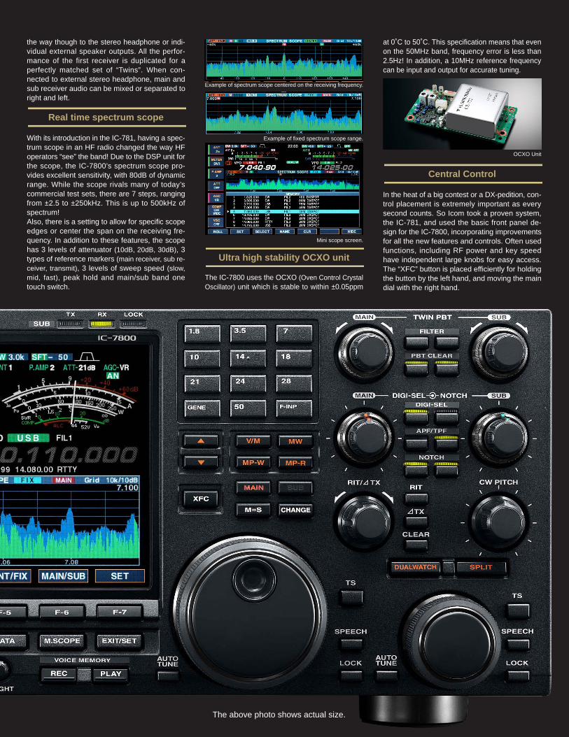
Central Control
In the heat of a big contest or a DX-pedition, con-trol placement is extremely important as everysecond counts. So Icom took a proven system,the IC-781, and used the basic front panel de-sign for the IC-7800, incorporating improvementsfor all the new features and controls. Often usedfunctions, including RF power and key speedhave independent large knobs for easy access.The “XFC” button is placed efficiently for holdingthe button by the left hand, and moving the maindial with the right hand.
OCXO Unit
The above photo shows actual size.
Ultra high stability OCXO unit
The IC-7800 uses the OCXO (Oven Control CrystalOscillator) unit which is stable to within ±0.05ppm
Example of spectrum scope centered on the receiving frequency.
Example of fixed spectrum scope range.
Mini scope screen.
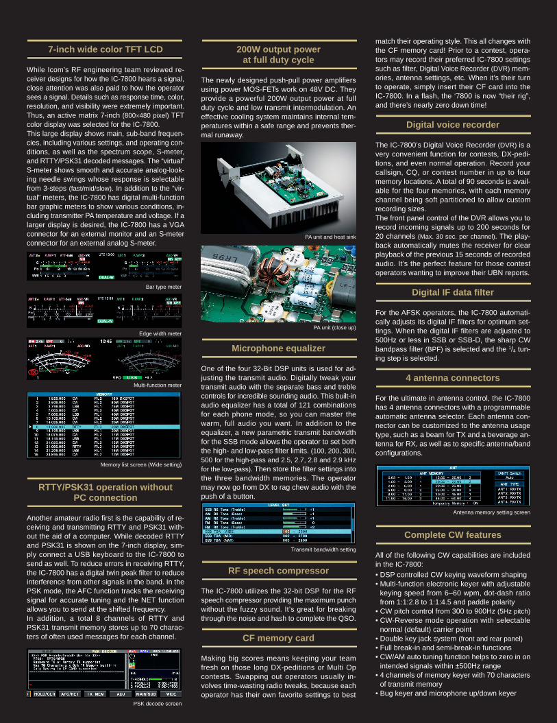
7-inch wide color TFT LCD
While Icom’s RF engineering team reviewed re-ceiver designs for how the IC-7800 hears a signal,close attention was also paid to how the operatorsees a signal. Details such as response time, color,resolution, and visibility were extremely important.Thus, an active matrix 7-inch (800×480 pixel) TFTcolor display was selected for the IC-7800. This large display shows main, sub-band frequen-cies, including various settings, and operating con-ditions, as well as the spectrum scope, S-meter,and RTTY/PSK31 decoded messages. The “virtual”S-meter shows smooth and accurate analog-look-ing needle swings whose response is selectablefrom 3-steps (fast/mid/slow). In addition to the “vir-tual” meters, the IC-7800 has digital multi-functionbar graphic meters to show various conditions, in-cluding transmitter PA temperature and voltage. If alarger display is desired, the IC-7800 has a VGAconnector for an external monitor and an S-meterconnector for an external analog S-meter.
RTTY/PSK31 operation without PC connection
Another amateur radio first is the capability of re-ceiving and transmitting RTTY and PSK31 with-out the aid of a computer. While decoded RTTYand PSK31 is shown on the 7-inch display, sim-ply connect a USB keyboard to the IC-7800 tosend as well. To reduce errors in receiving RTTY,the IC-7800 has a digital twin peak filter to reduceinterference from other signals in the band. In thePSK mode, the AFC function tracks the receivingsignal for accurate tuning and the NET functionallows you to send at the shifted frequency. In addition, a total 8 channels of RTTY andPSK31 transmit memory stores up to 70 charac-ters of often used messages for each channel.
200W output power at full duty cycle
The newly designed push-pull power amplifiersusing power MOS-FETs work on 48V DC. Theyprovide a powerful 200W output power at fullduty cycle and low transmit intermodulation. Aneffective cooling system maintains internal tem-peratures within a safe range and prevents ther-mal runaway.
Microphone equalizer
One of the four 32-Bit DSP units is used for ad-justing the transmit audio. Digitally tweak yourtransmit audio with the separate bass and treblecontrols for incredible sounding audio. This built-inaudio equalizer has a total of 121 combinationsfor each phone mode, so you can master thewarm, full audio you want. In addition to theequalizer, a new parametric transmit bandwidthfor the SSB mode allows the operator to set boththe high- and low-pass filter limits. (100, 200, 300,500 for the high-pass and 2.5, 2.7, 2.8 and 2.9 kHzfor the low-pass). Then store the filter settings intothe three bandwidth memories. The operatormay now go from DX to rag chew audio with thepush of a button.
RF speech compressor
The IC-7800 utilizes the 32-bit DSP for the RFspeech compressor providing the maximum punchwithout the fuzzy sound. It’s great for breakingthrough the noise and hash to complete the QSO.
CF memory card
Making big scores means keeping your teamfresh on those long DX-peditions or Multi Opcontests. Swapping out operators usually in-volves time-wasting radio tweaks, because eachoperator has their own favorite settings to best
match their operating style. This all changes withthe CF memory card! Prior to a contest, opera-tors may record their preferred IC-7800 settingssuch as filter, Digital Voice Recorder (DVR) mem-ories, antenna settings, etc. When it’s their turnto operate, simply insert their CF card into theIC-7800. In a flash, the ‘7800 is now “their rig”,and there’s nearly zero down time!
Digital voice recorder
The IC-7800’s Digital Voice Recorder (DVR) is avery convenient function for contests, DX-pedi-tions, and even normal operation. Record yourcallsign, CQ, or contest number in up to fourmemory locations. A total of 90 seconds is avail-able for the four memories, with each memorychannel being soft partitioned to allow customrecording sizes.The front panel control of the DVR allows you torecord incoming signals up to 200 seconds for20 channels (Max. 30 sec. per channel). The play-back automatically mutes the receiver for clearplayback of the previous 15 seconds of recordedaudio. It’s the perfect feature for those contestoperators wanting to improve their UBN reports.
Digital IF data filter
For the AFSK operators, the IC-7800 automati-cally adjusts its digital IF filters for optimum set-tings. When the digital IF filters are adjusted to500Hz or less in SSB or SSB-D, the sharp CWbandpass filter (BPF) is selected and the 1/4 tun-ing step is selected.
4 antenna connectors
For the ultimate in antenna control, the IC-7800has 4 antenna connectors with a programmableautomatic antenna selector. Each antenna con-nector can be customized to the antenna usagetype, such as a beam for TX and a beverage an-tenna for RX, as well as to specific antenna/bandconfigurations.
Complete CW features
All of the following CW capabilities are includedin the IC-7800:• DSP controlled CW keying waveform shaping• Multi-function electronic keyer with adjustable
keying speed from 6–60 wpm, dot-dash ratiofrom 1:1:2.8 to 1:1:4.5 and paddle polarity
• CW pitch control from 300 to 900Hz (5Hz pitch)• CW-Reverse mode operation with selectable
normal (default) carrier point• Double key jack system (front and rear panel)• Full break-in and semi-break-in functions• CW/AM auto tuning function helps to zero in on
intended signals within ±500Hz range• 4 channels of memory keyer with 70 characters
of transmit memory• Bug keyer and microphone up/down keyer
Bar type meter
Edge width meter
Multi-function meter
Transmit bandwidth setting
Antenna memory setting screen
PA unit and heat sink
PA unit (close up)
Memory list screen (Wide setting)
PSK decode screen
[Antenna line]• High speed automatic antenna tuner covers
HF and 50MHz bands.• BNC type Rx In/Out connectors for receiver
antenna or external attenuator, etc.
[Receiver]• General coverage receiver covers from
30kHz to 60MHz (* Some frequency bands arenot guaranteed. Depending on version.)
• Two types of receive preamplifiers:Preamp 1; Increase low level signal im-proving intermodulation characteristics Preamp 2; High gain preamplifier
• Built-in receive audio equalizer tweaks re-ceive audio with the separate bass and treblecontrols
• 7-step attenuator (3, 6, 9, 12, 18, 21dB and OFF)
• External speaker connectors for main andsub receiver
[Transmitter]• Tx monitor• 50 CTCSS tone encoder and decoder• VOX capability (Voice operated transmission)• All mode power control
[Operation]• Set mode function for flexible and speedy setting• Memory pad stores up to 5 or 10 operating
frequencies• Quick split function and frequency lock func-
tion for split operation• Triple band stacking register• SSB/CW synchronous tuning• Single knob control from squelch to RF gain• RIT and ∂Tx variable up to 9.999kHz• 1Hz pitch tuning and indication• 101 memories with 10-character alphanumeric• Auto tuning step function• Firmware update capability from your PC
• Built-in voice synthesizer announces operat-ing frequency, mode and signal strength.
• Programmed scan, memory scan, selectmemory scan, VSC scan and ∂F scan
• Main dial tension control• CI-V interface capability• Optical digital audio input/output • FFT scope averaging function for both PSK
and RTTY decoder• BNC type Transverter connector
Offset frequency is user programmable andactual frequency is displayed.
• UTC/Local Clock and timer function• Screen saver function
Supplied accessories:• CF memory card (64MB) • AC power cable • Spare fuses • Speaker plugs • Key plug• ACC plugs • Power plug • Pin plug• Rack mount handles
Other outstanding features
i !0o !1 !2 !3 !4 !5 !6 !7 !8 !9 @0 @1 @22 @22 @3
q w e r r ut y
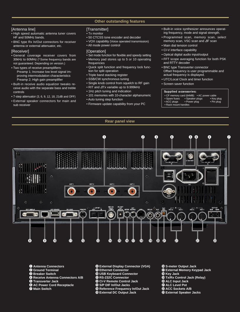
Antenna ConnectorsGround TerminalBreaker SwitchReceive Antenna Connectors A/BTransverter JackAC Power Cord ReceptacleMain Switch
External Display Connector (VGA)Ethernet ConnectorUSB Keyboard ConnectorRS-232C ConnectorCI-V Remote Control JackS/P DIF In/Out JacksReference Frequency In/Out JackExternal DC Output Jack
S-meter Output JackExternal Memory Keypad JackKey JackTx/Rx Control Jack (Relay)ALC Input JackALC Level PotACC Sockets A/BExternal Speaker Jacks
qwertyu
!6!7!8!9@0@1@2@3
io!0!1!2!3!4!5
Rear panel view
1-1-32, Kamiminami, Hirano-ku, Osaka 547-0003, Japan Phone: +81 (06) 6793 5302 Fax: +81 (06) 6793 0013 Count on us!URL: http://www.icom.co.jp/world/index.html
2380 116th Avenue NE, Bellevue, WA 98004, U.S.A.Phone : +1 (425) 454-8155Fax : +1 (425) 454-1509E-mail : [email protected] : http://www.icomamerica.com
Communication EquipmentHimmelgeister Str. 100, D-40225 Düsseldorf, GermanyPhone : +49 (0211) 346047Fax : +49 (0211) 333639E-mail : [email protected] : http://www.icomeurope.com
A.B.N. 88 006 092 575Unit 1 / 103 Garden Road,Clayton VIC 3168 AustraliaPhone : +61 (03) 9549 7500Fax : +61 (03) 9549 7505 E-mail : [email protected] : http://www.icom.net.au
Unit 9, Sea St., Herne Bay, Kent, CT6 8LD, U.K.Phone : +44 (01227) 741741Fax : +44 (01227) 741742E-mail : [email protected] : http://www.icomuk.co.uk
Zac de la Plaine, 1, Rue Brindejonc des Moulinais BP 5804, 31505 Toulouse Cedex, FrancePhone : +33 (5) 61 36 03 03Fax : +33 (5) 61 36 03 00E-mail : [email protected] : http://www.icom-france.com
Crta. de Gracia a Manresa Km. 14,75008190 Sant Cugat del Valles Barcelona, SpainPhone : +34 (93) 590 26 70Fax : +34 (93) 589 04 46E-mail : [email protected] : http://www.icomspain.com
146A Harris Road, East Tamaki, Auckland, New ZealandPhone : +64 (09) 274 4062Fax : +64 (09) 274 4708E-mail : [email protected] : http://www.icom.co.nz
Glenwood Centre #150-6165 Highway 17, Delta, B.C., V4K 5B8, CanadaPhone : +1 (604) 952-4266Fax : +1 (604) 952-0090E-mail : [email protected] : http://www.icomcanada.com
JP98/14190QA TW03/00288EM
Icom Inc. (Japan), is an ISO 9001 and ISO 14001 certification acquired company.
6F No. 68, Sec. 1 Cheng-Teh Road, Taipei, Taiwan, R.O.C.Phone : +886 (02) 2559 1899Fax : +886 (02) 2559 1874E-mail : [email protected] : http://www.asia-icom.com
10C07, Long Silver Mansion, No.88, Yong DingRoad, Haidian District, Beijing, 100039, ChinaPhone : +86 (010) 5889 5391/5392/5393Fax : +86 (010) 5889 5395E-mail : [email protected] : http://www.bjicom.com
Sopot, 3 maja 54, PolandPhone : +48 (58) 550 7135Fax : +48 (58) 551 0484E-mail : [email protected] : http://www.icompolska.com.pl
Printed in Japan
Your local distributor/dealer:
04JS000D* © 2004–2005 Icom Inc.
• Frequency coverage*1 : U.S.A. Version
Rx 0.030– 60.000MHz*2
Tx 1.800– 1.999MHz*2 3.500– 3.999MHz5.3305, 5.3465, 5.3665, 5.3715, 5.4035MHz*3
7.000– 7.300MHz 10.100–10.150MHz14.000– 14.350MHz 18.068–18.168MHz21.000– 21.450MHz 24.890–24.499MHz28.000– 29.700MHz 50.000–54.000MHz
Europe VersionRx 0.030– 60.000MHz*2
Tx 0.1357– 0.1378MHz 1.800– 1.999MHz3.400– 4.099MHz*2 6.900– 7.499MHz*2
9.900– 10.499MHz*2 13.900–14.499MHz*2
17.900– 18.499MHz*2 20.900–21.499MHz*2
24.400– 25.099MHz*2 28.000–29.999MHz*2
50.000– 54.000MHz*2
*1 Frequency ranges vary depending on version.*2 Some frequency ranges are not guaranteed.*3 Carrier point frequency.
• Mode : USB, LSB, CW, RTTY, PSK31, AM, FM• Number of channels : 101 (99 regular, 2 scan edges)• Antenna impedance : 50Ω unbalanced (Tuner off)• Antenna connector : SO-239×4 and BNC×2• Power supply requirement: 85–265V AC• Temperature range : 0˚C to +50˚C; +32˚F to +122˚F• Frequency stability : Less than ±0.05ppm
(0˚C to +50˚C, after warm up)• Frequency resolution : 1Hz (minimum)• Power consumption : Tx Max. power 800VA
Rx Stand-by 200VA (typ.)Max. audio 210VA (typ.)
• Dimensions : 424(W)×149(H)×435(D) mm;(projections not included) 1611⁄16(W)×57⁄8(H)×171⁄8(D) in
• Weight (approx.) : 25kg; 55lb
• Output power (continuously adjustable) : SSB, CW, RTTY, PSK31, FM 5–200WAM 5–50W137kHz, CW* More than –20dBm(* Depending on version.)
• Modulation system : SSB DPSN modulationAM Digital low power modulationFM Digital phase modulation
• Spurious emission : More than 60dB (HF bands)More than 70dB (50MHz band)
• Carrier suppression : More than 63dB• Unwanted sideband suppression:
More than 80dB• ∂TX variable range : ±9.999kHz• Microphone impedance : 600Ω (8-pin connector)
• Receive system : Double conversion super-heterodyne system
• Intermediate frequencies : 1st 64.455MHz (Main receiver)
64.555MHz (Sub receiver)2nd 36kHz
• Sensitivity (typical) :SSB, CW, RTTY, PSK31, FM (BW: 2.4kHz at 10dB S/N)
0.1–1.799MHz 0.5µV*1
1.8–29.999MHz 0.16µV*1
50.0–54.0MHz 0.13µV*2
AM (BW: 6kHz at 10dB S/N)0.1–1.799MHz 6.3µV*1
1.8–29.999MHz 2µV*1
50.0–54.0MHz 1µV*2
FM (BW: 15kHz at 12dB SINAD)28–29.999MHz 0.5µV*1
50.0–54.0MHz 0.32µV*2
*1 Pre-amp 1 is ON, *2 Pre-amp 2 is ON.• Squelch sensitivity (Pre-amp: OFF):
SSB, CW, RTTY, PSK31 Less than 5.6µVFM Less than 1µV
• Selectivity (representative value): SSB (BW: 2.4kHz) More than 2.4kHz/–3dB
Less than 3.6kHz/–60dBCW (BW: 500Hz) More than 500Hz/–3dB
Less than 700Hz/–60dBRTTY, PSK31 More than 360Hz/–6dB(BW: 350kHz) Less than 650Hz/–60dBAM (BW: 6kHz) More than 6.0kHz/–3dB
Less than 15.0kHz/–60dBFM (BW: 15kHz) More than 12.0kHz/–6dB
Less than 20.0kHz/–60dB• Spurious and image : More than 70dB
rejection ratio • Audio output power : More than 2.6W at 10% distortion
with an 8Ω load• RIT variable range : ±9.999kHz• PHONES connector : 3-pin connector 6.35 (d) mm (1⁄4″)• EXT SP connector : 2-pin connector 3.5 (d) mm
(1⁄8″)/8Ω
GENERAL
RECEIVER
TRANSMITTER
The LCD display may have cosmetic imperfections that appearas small or dark spots. This is not a malfunction or defect, but anormal characteristic of LCD displays.
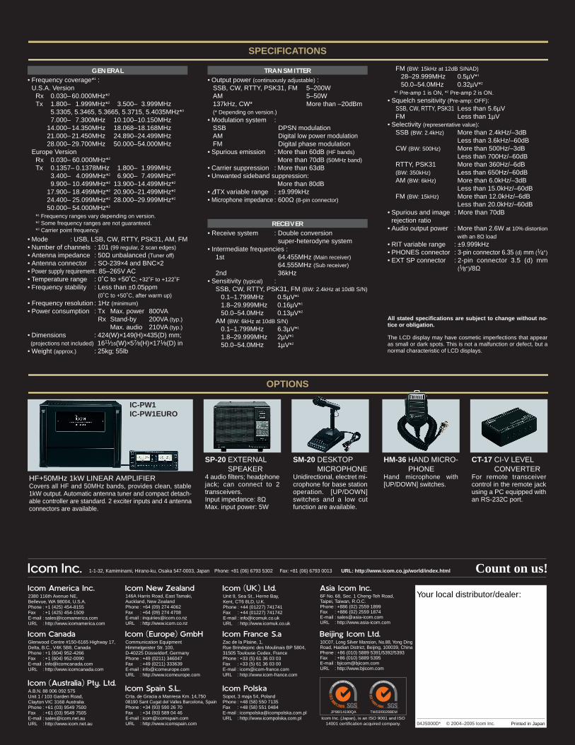
CT-17 CI-V LEVELCONVERTER
For remote transceivercontrol in the remote jackusing a PC equipped withan RS-232C port.
SM-20 DESKTOPMICROPHONE
Unidirectional, electret mi-crophone for base stationoperation. [UP/DOWN]switches and a low cutfunction are available.
HF+50MHz 1kW LINEAR AMPLIFIERCovers all HF and 50MHz bands, provides clean, stable1kW output. Automatic antenna tuner and compact detach-able controller are standard. 2 exciter inputs and 4 antennaconnectors are available.
SP-20 EXTERNALSPEAKER
4 audio filters; headphonejack; can connect to 2transceivers.Input impedance: 8ΩMax. input power: 5W
HM-36 HAND MICRO-PHONE
Hand microphone with[UP/DOWN] switches.
All stated specifications are subject to change without no-tice or obligation.
SPECIFICATIONS
OPTIONS
IC-PW1IC-PW1EURO