ICOM IC-735 Repair of Hard-To-Rotate Tuning Dial … IC-735 Repair of Hard-To-Rotate Tuning Dial...
11
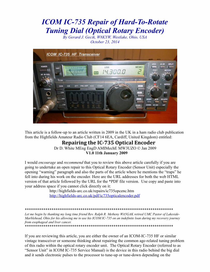
ICOM IC-735 Repair of Hard-To-Rotate Tuning Dial (Optical Rotary Encoder) By Gerard J. Gecik, W8KYW, Westlake, Ohio, USA October 23, 2014 This article is a follow-up to an article written in 2009 in the UK in a ham radio club publication from the Highfields Amateur Radio Club (CF14 6EA, Cardiff, United Kingdom) entitled: Repairing the IC-735 Optical Encoder Dr D. White MEng EngD AMIMechE MW3UZO © Jan 2009 V1.0 11th January 2009 I would encourage and recommend that you to review this above article carefully if you are going to undertake an open repair to this Optical Rotary Encoder (Sensor Unit) especially the opening “warning” paragraph and also the parts of the article where he mentions the “traps” he fell into during his work on the encoder. Here are the URL addresses for both the web HTML version of that article followed by the URL for the *PDF file version. Use copy and paste into your address space if you cannot click directly on it: http://highfields-arc.co.uk/repairs/ic735opcenc.htm http://highfields-arc.co.uk/pdf/ic735opticalencoder.pdf ************************************************************************ Let me begin by thanking my long time friend Rev. Ralph R. Metheny WA5GAK retired UMC Pastor of Lakeside- Marblehead, Ohio for his allowing me to use his ICOM IC-735 on an indefinite loan during my recovery journey from esophageal and liver cancer. ************************************************************************ If you are reviewing this article, you are either the owner of an ICOM-IC-735 HF or similar vintage transceiver or someone thinking about repairing the common age-related tuning problem of this radio within the optical rotary encoder unit. The Optical Rotary Encoder (referred to as “Sensor Unit” in ICOM IC-735 Service Manual) is the device in this radio behind the big dial and it sends electronic pulses to the processor to tune-up or tune-down depending on the
Transcript of ICOM IC-735 Repair of Hard-To-Rotate Tuning Dial … IC-735 Repair of Hard-To-Rotate Tuning Dial...
ICOM IC-735 Repair of Hard-To-RotateTuning Dial (Optical Rotary Encoder)
By Gerard J. Gecik, W8KYW, Westlake, Ohio, USAOctober 23, 2014
This article is a follow-up to an article written in 2009 in the UK in a ham radio club publication from the Highfields Amateur Radio Club (CF14 6EA, Cardiff, United Kingdom) entitled:
Repairing the IC-735 Optical EncoderDr D. White MEng EngD AMIMechE MW3UZO © Jan 2009
V1.0 11th January 2009
I would encourage and recommend that you to review this above article carefully if you are going to undertake an open repair to this Optical Rotary Encoder (Sensor Unit) especially the opening “warning” paragraph and also the parts of the article where he mentions the “traps” he fell into during his work on the encoder. Here are the URL addresses for both the web HTML version of that article followed by the URL for the *PDF file version. Use copy and paste into your address space if you cannot click directly on it:
http://highfields-arc.co.uk/repairs/ic735opcenc.htmhttp://highfields-arc.co.uk/pdf/ic735opticalencoder.pdf
************************************************************************Let me begin by thanking my long time friend Rev. Ralph R. Metheny WA5GAK retired UMC Pastor of Lakeside-Marblehead, Ohio for his allowing me to use his ICOM IC-735 on an indefinite loan during my recovery journey from esophageal and liver cancer.************************************************************************
If you are reviewing this article, you are either the owner of an ICOM-IC-735 HF or similar vintage transceiver or someone thinking about repairing the common age-related tuning problem of this radio within the optical rotary encoder unit. The Optical Rotary Encoder (referred to as “Sensor Unit” in ICOM IC-735 Service Manual) is the device in this radio behind the big dial and it sends electronic pulses to the processor to tune-up or tune-down depending on the

direction you turn the dial. It is a part that ICOM no longer supplies or repairs and it seems is only occasionally available on eBay from a seller who is taking apart an old IC-735 that is beyond use for other reasons.
The above article discussed two very common problems with this encoder causing the following problems: frequency not changing when dial is turned or frequency digits jumping forward or backward several steps, or seeming to freeze every now and then, and/or not working at all. It is a problem centered in the encoder possibly because of (1) a warped or dirty “rotary mask” disk (a very thin metal disk with several hundred slits or windows; this disk rotates as you turn the dial. This rotary mask interfaces directly with a “static or stationary mask” that has two sets of five slits in it as explained in the above article with many great photo shots. This allows light from an Infrared Emitting Diode to shine thru the windows and be received by Photo Sensing Transistors with the electronic pulses created being sent to the processor). The other possible problem (2) is within the optoelectronics contained on the circuit-board on this encoder unit. There is either a faulty light-source (Infrared-LED emitting diodes) or faulty light-receptor (Photo Sensing Transistors)…there are two sets of each on the encoder circuit board (see the pictures, the explanations, and the solutionsto these electronic problems in Dr. D. White’s article).
**********************************************************************
Now to my problem: a very hard to rotate Optical Rotary Encoder dial. My radio, an ICOM IC-735, sat in a non-temperature controlled room unused but covered for protection for about 10 years in northern Ohio where the fluctuations in temperature and humidity can be extreme in summer and winter. Overall, the radio has been checked out and works fine with full power and correct operation of all functions, even the 3-volt lithium battery for the memory is remembering what was left in there all these years and the battery looks like it’s the original! The Up and Down Microphone buttons still works fine. Except for a slightly scratchy squelch and a very hard to rotate Optical Rotary Encoder dial the radio survived.
Why would it be so hard to rotate the dial and what to do about it??? This is what I wish to address here and add to the discussion of the Highfields Amateur Radio Club’s 2009 article.
If you wish to open this radio for this or any repair job, I recommend the following: good lighting, plenty of room, tools (mainly Phillips screwdrivers including a small size PH00), and a container to hold parts as they are removed. Also you should have the User and the Service manual for the ICOM IC-735 available at least on your computer screen for viewing and reference. If you print it out and put it in a binder, you can use it for ready reference in the future. You can easily find the IC-735 User Manual and Service Manual and Large *jpg format copies of the actual schematics at several places on the web but it is easiest to get it at RigPix.com. Here is the actual URL address to the page you need: http://www.rigpix.com/icom/ic735.htm look down the column labeled specifications till you see “User Manual” and “Service Manual” and “Schematics”. Click to download each as needed.
If the tuning-dial on your radio is hard to turn, first check to make sure that the “Tuning Control Tensioner” is not adjusted too much to make it hard-to-turn. That would be a quick fix! Directlybelow the large tuning knob on the bottom side of the radio is an access hole (see Fig 1 below). You should see recessed in this hole a Phillips head screw. Turning it clockwise to tighten it will increase tension on the dial and turning it counterclockwise will release tension on the dial (see page 27 of the User’s Manual in the section called Brake Adjustment). Be careful not to loosen the screw too much that it, and a little spring it goes through, falls out because it can get lost in the front panel of the radio. Not good! If the screw and spring come out into your hand…that is

ok; you are lucky!
Fig. 1
Note regarding this tensioner-screw: if you go ahead and want to remove the optical rotary encoder unit as discussed in the next paragraphs, this tensioner-screw may be out too far for the encoder to be delivered or pulled through the front panel easily, so just tighten the screw inward to shrink the vertical size of the encoder unit as it comes out of the front panel. You will understand what I mean when you go ahead with the removal.
Disassembly: You can start by removing the large tuning knob from the front of the radio using a 5/64th inch (2mm) Allen hex key (Allen wrench) to access the set-screw (see Fig 2 below).
Fig. 2
You may need to wiggle that large knob a little as you ease it off the shaft of the encoder. There is no flat surface on that encoder shaft, so when you replace the knob during reassembly there is no correct or absolute position to tighten the set-screw.
Removal of the large knob will expose the optical rotary encoder unit that is held in place by 4 Phillips-head screws (see Fig 3 below). If you remove these 4 screws you can now pull this unit out only a short distance limited by the length of the 6-wire harness behind it (see Fig 4 and 4a below). This wiring harness terminates in a white chassis plug (Plug #1 labeled P1 on page 10-5

of the schematics and diagrams in the service manual) (see Fig 3a below for a picture of P1) which connects to the bottom main circuit-board connector (Connector #1 labeled as Connector J1; also seen in the diagram on page 10-5 of the service manual).
Fig. 3
Fig 3a
If you are going to do any work on this optical rotary encoder (sensor unit) as a whole unit, especially having to do with the optoelectronics (diodes, transistors), you should follow the procedure to open the metal case of the radio top and bottom, involving many screws, to access the connector on the main bottom circuit board. This way the whole optical rotary encoder unit with wiring will be in your hands.
If, however, you have a problem, like mine did, with a hard-to-turn dial, and you know that the electronics are working fine because the dial works changing frequencies up and down correctly, you may be able to get away without opening the whole radio! Since I did not know any better and was learning as I went along, I did take my optical rotary encoder unit out completely with wiring after opening the whole radio. It was not till I was finished with the repair that I realized that I could have done it all from the front of the radio as you see it in Fig.4 and 4a below). Oh well! So this means that if you are only repairing the encoder unit because it is hard to turn, good news, you probably will not have to open the whole radio. Yeah!!!

Fig.4 Fig. 4a
One suggestion I found on a web forum for this hard-to-turn dial problem was to place two small drops of fine machine oil (i.e. BreakFree CLP cleaner, lubricant, protector which will not clump or dry out ever; see Fig.5 below) down along the shaft at 12 o’clock and 6 o’clock (see Fig. 5a below) and let it sit upright for 24-48 hrs allowing it to work its way into the bushing area where the shaft is likely binding. Attention: I know now that this will not work because a plastic mount holding the rotary mask is tightly adhered to the shaft before the bushing and will not let anything pass by it. The oil will never make it to the bushing that needs it. Also you may try this same oil drops technique from the rear and stand that end up for a day or two (see Fig. 5b below). I did not try it. My opinion is: only disassembly and pulling the shaft out of the bushing tunnel will work to free it to spin again. If you do the same project I am describing here, you will undoubtedly agree with me on this point!
Fig. 5Fig. 5a Fig. 5b
After you have gently pulled the optical rotary encoder sensor unit out of the front of the radio (see Fig. 6 below), consider making some small line marks on each side of the small circuit board with a fine tip Sharpie marker and continue the marks on to the metal housing of the encoder to line it up during reassembly (see 7 below). Then carefully remove the two Phillips screws holding the circuit board on the top of the unit. Very carefully lift the circuit board straight out of its perch so it does not bump the rotary-masks inside the unit. Now you will have the optical rotary encoder unit in one hand and the optoelectronics board (see Fig. 8 and 9 below)in your other hand. From this point on till it is reassembled, be careful not to allow dust, dirt, lint, or moisture to get in that area where you removed the circuit board or any other area of the unit once it is opened to daylight.

Fig. 6 Fig. 7
Fig. 8 Fig. 9
***********************************************************************Protecting the yet unseen rotary-mask inside against damage or further damage is our #1 priority in all the following steps!***********************************************************************Look at the optical rotary encoder unit and study it for how it functions on the outside and this will help you know after you see the inside why there is a metal-spacer and tensioning screw, a spring, washers (both metal and plastic), and a locking-clip in the rear of the unit (see Fig. 10 below).
Fig. 10
Place the optical rotary encoder sensor unit in a vice to hold it steady front-side down. Make sure the tensioner screw is turned counter-clockwise to a fully loosened position. You should be able to spin that large brass-looking spring you see below the washers. When you take the locking-clip out there is no tension there to make everything fly away and get lost. First take away the locking-clip (see Fig. 11 below) and then the washers (plastic and metal; see Fig. 12 below)) and then the spring(see Fig. 13 below) and then the metal spacer (see Fig. 14 below) thatactually applies tension to the spring when that tensioner-screw is tightened. Ah!!! Now I see how it all works. Wow!

Fig. 11 Fig. 12
Fig. 13 Fig. 14
Now you can see the gray 1” (5cm) extension of the housing (see Fig. 15 below) that the shaft runs through. This is the tunnel or bushing that the shaft inside spins or is supposed to spin very easily! The problem is dirt or dried grease or both inside that tunnel.
Fig. 15
Carefully free the unit from your vice and place it down in front of you. Do not push or pull either end of the shaft just yet. Remember that in everything we are protecting that rotary-mask inside! We shall see it soon! Take a medium size flat edge screwdriver and put light prying pressure under side tabs of the front metal plate (see Fig. 16 below). A little bit on one side and then move to the other side and the plate will come off easily. During reassembly later this metal plate will snap back into a locked position on the housing with equal finger squeezing pressure on each side. Now we can see the rotary-mask (see Fig. 16a below) and some of the insides of the encoder unit. If you are going to repair that rotary-mask by removing it from the rotary-shaft you will need to remove the 3 Phillips 00 screws. Make alignment marks with your Sharpie (also see Fig. 16a below) to help you on reassembly. You cannot see the stationary-maskyet. It is flat against the rotary-mask down in the area where the optoelectronics board is situatedwhen present. Remember what I said about dust, dirt, lint, and liquid…….verboten!!!
Fig. 16 Fig. 16a

Have a pair of pliers or vice-grips available to grasp the shaft for the next step and also you might have the big knob tuning dial with the shaft-hole facing up near-by to hold the shaft upright or downright after you remove it (see Fig. 17d below) in the next step especially when you need your hands to be free.
Take the rotary encoder unit in your hand with the smooth round shaft and rotary-mask facing upwards. Lightly place the back-end of the shaft that has the indent for the locking-clip (see Fig.17) on the vice or table-top and push downwards pushing the shaft and the attached rotary-mask forward and upward. You will begin to see the separation of the rotary-mask from the stationary-mask which remains. When that back part of the shaft is even with the housing unit and you cannot push it anymore, you should be able to grasp the front tip of the shaft and it should begin to turn easier as it is coming out of the bushing tunnel. This is a good time to grasp that shaft with a small size vice-grip or pliers. As you rotate the shaft, look at the rotary-mask for signs of warping. You will be able to distinguish it when it is still close to the stationary-mask. Now slowly continue to pull it all the way out of the bushing housing. You need to be careful not to bump the stationary mask with the back-end of the rotary shaft. You are now holding the shaft with the rotary-mask attached to it.. Examine it and you will see grease and possibly other debrison the part of the shaft that was in the bushing tunnel. Place that rotary-mask and shaft down intothe large tuning-knob dial to hold or upright in a vice-grip. Never rest or lean that shaft with pressure on the rotary mask (it will bend and warp and be ruined).
Fig. 17
Fig. 17a Fig. 17b
Fig. 17c Fig. 17d

You can now see the stationary-mask (see Fig. 18 below) with its two sets of five slit windows along the lower edge of the encoder unit held in place by two Phillips screws. No need to remove this stationary-mask unless it is dirty and the window slits are blocked.
Fig. 18
Look for debris inside the bushing tunnel now (see Fig. 19 below). Even if you do not see any dirt or grime, it still needs to be cleaned. Being very careful of lint, take a q-tip or two dipped in tuner-cleaner and spin it only in one direction in and out of that bushing tunnel. You will see old dirt and debris on the Q-tip and now the tunnel will look shiny and clean like a cylinder shaft thathas been honed-out. Dip a fresh Q-tip in fine machine oil (i.e. BreakFree-CLP) or some high quality fine lithium grease, and once again spinning in one direction lubricate that bushing tunnel. Watch closely for lint strands from the Q-tip anywhere…they need to be removed!
Fig. 19
Next we need to clean the rotary-shaft with the rotary-mask still attached unless you needed to remove the rotary-mask for repair (unwarping or flattening procedure) not discussed in this article. This removal of the rotary-mask needs to be done very delicately!!! I would only removethe rotary-mask if it is obviously warped. Mine was not warped! As you can see, I did remove the three Phillips 00 screws (see Fig. 20 below) holding the mask onto the black plastic-mount

before I removed it from the unit housing. This was very risky on my part. I wish I had not removed those three screws. It was not necessary for my type of “hard to turn dial” problem. I would not do this again unless I was doing a salvage maneuver on a warped rotary-mask. Here is the reason: as you take out these little screws occasionally the screws pull little plastic debris or little barbs that it had been holding onto for years. Even a couple of granules of this plastic re-sandwiched after replacing the screws later to hold the rotary-mask may cause an uneven lift of the mask and mimic a warped disc problem. So if you have to remove the screws do it early like I did it, but watch for little plastic particles or shreds. Use extra-fine-tipped forceps to remove this debris.
Fig. 20
Now on to actually cleaning the rotary-shaft: while holding the shaft on the smooth end oppositethe dirt and grease (best held with a small vice-grip or pliers), you need to clean the other end without touching the rotary-mask (see Fig. 21). Again use Q-tips dipped in tuner cleaner to cleanoff all the old grease, debris and excess cleaner product. You will see a short segment of the shaft that has a smaller diameter that creates a pocket that was and can be used as a grease reservoir. You may do the same with some fine lithium grease or liberally coat the shaft with fine machine oil but do not get anything on the rotary-mask that can work its way later by gravityand block a window or two or more.
Fig. 21
******************************************************************************
Reassembly: place the empty encoder unit shell in the vice to hold it by the long bushing section. The open shell section should be facing upwards. Now you should pick-up the shaft with rotary-mask attached and holding the freshly oiled or lubed shaft pointing downwards (so no oil can roll by gravity towards the rotary-mask) place it back in the bushing-tunnel carefully

pushing it in to the point where both the rotary-mask and the stationary mask are married again looking like one disk. The shaft now should rotate freely in the bushing and unit housing and you should be very happy! Reattach the metal protection plate with equal finger pressure on each side till it snaps into place. Now remember that shaft can still move in and out easily, because it is not locked in with the locking-clip on the other end yet. So do not put pressure on the shaft just yet…we are still protecting the rotary-mask now unseen inside the unit. Carefully loosen the vice and place back in the vice to hold horizontal held by two of the four sides. Replace the brass spacing bracket, the spring, the metal washer, the plastic washer, and carefully place the locking clip in place. Slight pushing pressure from the front on the smooth part of the shaft will help you to get the locking clip back in its groove on the back end of the shaft. You may need to use a small hemostat or a long nose-pliers, or a locking-clip tool to help get that clipback on the now very spinnable shaft. Gently reattach the optoelectronics board without bumping the rotary-masks and lining up your marking lines made prior and replace the two Phillips screws. Tighten the tensioner screw a little to help you get the encoder unit back throughthe front panel. If you did a complete removal of the encoder unit, plug in P1 into the proper connector on the bottom main circuit board at Connector J1. At this point, or even before the replacing the 4 Phillips screws holding the encoder unit to the front panel mount, you can fire up the radio and spin the shaft to see if it works correctly…it should hopefully!!! Replace the dial and tighten it with the Allen wrench and you are good to go. Thanks for reading. Hope this helps bring some of these ICOM IC-735’s back to life.
The only other way to replace this tuning optical rotary encoder unit with a more modern unit involves some expert work. I would recommend that you watch the video on YouTube called: ICOM IC-735 Repair/ Replacement Optical Rotary Encoder Dial by TRXBench an excellent 1hr05 min video that shows this Expert Amateur Radio Technician from Germany replacing the opticalrotary encoder unit of an ICOM IC-735 with a modern encoder unit manufactured by Bourns. This gentleman has several excellent videos on the testing and repair of various amateur radio problems. Search YouTube for TRXBench. Enjoy!
This is Gerry Gecik,W8KYW, from northern Ohio, USA saying 73 and have fun!!!