ICE Emulator for 386/486 - Lauterbach · ICE Emulator for 386/486 1 ... or Virtual 8086 Mode; off:...
99
ICE Emulator for 386/486 1 ©1989-2018 Lauterbach GmbH ICE Emulator for 386/486 TRACE32 Online Help TRACE32 Directory TRACE32 Index TRACE32 Documents ...................................................................................................................... ICE In-Circuit Emulator ................................................................................................................. ICE Target Guides ...................................................................................................................... ICE Emulator for 386/486 ........................................................................................................ 1 WARNING .............................................................................................................................. 6 Quick Start ............................................................................................................................ 7 Troubleshooting ................................................................................................................... 12 Hang-Up 12 Dualport Errors 13 FAQ ........................................................................................................................................ 14 Configuration ........................................................................................................................ 17 DIP-Switch Setting of 386SX/CX 17 DIP-Switch Setting of 486 18 Cableset 19 Basics .................................................................................................................................... 20 Emulation Modes 20 SYStem.Clock Clock generation 22 Dualport Access 22 General SYStem Settings and Restrictions ....................................................................... 23 General Restrictions 23 SYStem.Option BreakWin Break window 23 SYStem.Option FAST High speed mode 24 SYStem.Option FASTA High speed mode A 24 SYStem.Option ONCE On-circuit emulation 24 SYStem.Option PreMap Address lines 25 SYStem.Option SYNCH Synchronization mode 26 SYStem.Option TestClock Clock fail detection 26 SYStem.Option V33 3.3 V power fail detection 27 Continue with CPU specific Special Settings and Restrictions 27 Special Settings 386EX (no SMMC) and Restrictions ....................................................... 28 Restrictions 386EX (no SMMC) 28 SYStem.Option BreakNMI Break with 2nd NMI 30
-
Upload
trinhkhanh -
Category
Documents
-
view
241 -
download
0
Transcript of ICE Emulator for 386/486 - Lauterbach · ICE Emulator for 386/486 1 ... or Virtual 8086 Mode; off:...

ICE Emulator for 386/486
TRACE32 Online Help
TRACE32 Directory
TRACE32 Index
TRACE32 Documents ......................................................................................................................
ICE In-Circuit Emulator .................................................................................................................
ICE Target Guides ......................................................................................................................
ICE Emulator for 386/486 ........................................................................................................ 1
WARNING .............................................................................................................................. 6
Quick Start ............................................................................................................................ 7
Troubleshooting ................................................................................................................... 12
Hang-Up 12
Dualport Errors 13
FAQ ........................................................................................................................................ 14
Configuration ........................................................................................................................ 17
DIP-Switch Setting of 386SX/CX 17
DIP-Switch Setting of 486 18
Cableset 19
Basics .................................................................................................................................... 20
Emulation Modes 20
SYStem.Clock Clock generation 22
Dualport Access 22
General SYStem Settings and Restrictions ....................................................................... 23
General Restrictions 23
SYStem.Option BreakWin Break window 23
SYStem.Option FAST High speed mode 24
SYStem.Option FASTA High speed mode A 24
SYStem.Option ONCE On-circuit emulation 24
SYStem.Option PreMap Address lines 25
SYStem.Option SYNCH Synchronization mode 26
SYStem.Option TestClock Clock fail detection 26
SYStem.Option V33 3.3 V power fail detection 27
Continue with CPU specific Special Settings and Restrictions 27
Special Settings 386EX (no SMMC) and Restrictions ....................................................... 28
Restrictions 386EX (no SMMC) 28
SYStem.Option BreakNMI Break with 2nd NMI 30
ICE Emulator for 386/486 1 ©1989-2018 Lauterbach GmbH

SYStem.Option Protected Real mode/protected mode 31
SYStem.Option Prot16 Protected mode: 16 bit/32 bit code 32
SYStem.Option IDT Interrupt descriptor table base 33
Special Settings 386EX (SMMC) and Restrictions ............................................................ 34
Restrictions 386EX (SMMC) 34
SYStem.Option BOOT Real mode boot segment 35
SYStem.Option Protected Real mode/protected mode 36
SYStem.Option Prot16 Protected mode: 16 bit/32 bit code 38
SYStem.Option IDT Interrupt descriptor table base 39
Special Settings 386SX, 386CX, 386DX and 486 (no SMMC) and Restrictions .............. 40
Restrictions 386SX, 386CX, 386DX and 486 (no SMMC) 40
SYStem.Option Protected Real mode/protected mode 42
SYStem.Option Prot16 Protected mode: 16 bit/32 bit code 43
SYStem.Option IDT Interrupt descriptor table base 44
SYStem.Option Wait Wait cycles 44
Special Settings 486 (SMMC) and Restrictions ................................................................. 46
Restrictions 486 (SMMC) 46
SYStem.Option BOOT Real mode boot segment 47
SYStem.Option Protected Real mode/protected mode 47
SYStem.Option Prot16 Protected mode: 16 bit/32 bit code 49
SYStem.Option IDT Interrupt descriptor table base 50
SYStem.Option CACHE Disable cache 50
SYStem.Option BURST Disable burst 51
SYStem.Option Wait Wait cycles 51
Specific System Settings ..................................................................................................... 53
Exception Control ................................................................................................................ 54
Schematics 55
Reset Input 55
SMI (386CX, 386EX, 486) 55
NMI 56
HOLD 56
DMA Modes 57
SYStem.Line HOLD Enable HOLD line (emulation stopped) 57
eXception.Activate Force exception 58
eXception.Enable Enable exception 59
eXception.Trigger Trigger on exception 61
eXception.Pulse Stimulate exception 62
Interrupt Stimulation 62
Mapping ................................................................................................................................. 63
MAP.PRE Premapper 63
MAP.BUS Buswidth mapping 64
ICE Emulator for 386/486 2 ©1989-2018 Lauterbach GmbH

MAP.NoCache] No cache mapping 64
FPU ........................................................................................................................................ 65
MMU ....................................................................................................................................... 66
MMU.DUMP Dump descriptor tables 66
MMU.SCAN Scan descriptor tables 67
MMU.PDUMP Dump page tables 67
MMU.PSCAN Scan page tables 67
Special Functions ................................................................................................................. 68
Memory Classes ................................................................................................................... 69
Overview 69
Real Mode Addressing 71
Protected Mode Addressing 71
State Analyzer ....................................................................................................................... 72
Keywords for the Trigger Unit 72
General 386/486 Keywords for the Trigger Unit 72
386EX Keywords for the Trigger Unit 73
486 Keywords for the Trigger Unit 73
Keywords for the Display 74
General 386/486 Keywords 74
386SX, 386DX Keywords 74
386CX Keywords 74
386EX Keywords 75
486 Keywords 75
Dequeueing 75
Port Analyzer ........................................................................................................................ 76
Keywords for the Portanalyzer (386EX) 76
Input Connector for free Channels (386EX) 77
Compiler ................................................................................................................................ 78
Compiler Support Real Mode 78
Compiler Support Protected Mode 79
3rd Party Tool Integration .................................................................................................... 80
Realtime Operation Systems ............................................................................................... 81
Emulation Frequency ........................................................................................................... 82
Emulation Modules .............................................................................................................. 83
Module Overview 83
Order Information 84
Operating Voltage ................................................................................................................ 85
Physical Dimensions ........................................................................................................... 86
Adapter .................................................................................................................................. 93
ICE Emulator for 386/486 3 ©1989-2018 Lauterbach GmbH

ICE Emulator for 386/486 4 ©1989-2018 Lauterbach GmbH
ICE Emulator for 386/486
Version 16-Nov-2018
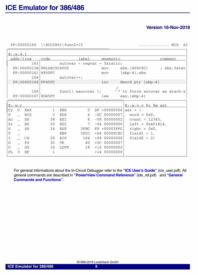
For general informations about the In-Circuit Debugger refer to the “ICE User’s Guide” (ice_user.pdf). All general commands are described in “PowerView Command Reference” (ide_ref.pdf) and “General Commands and Functions”.
PP:00000164 \\SCO386I\func2+15 ............. MIX AI
E::w.d.laddr/line code label mnemonic comment
163 autovar = regvar = fstatic;PP:0000015B 8B1D6C0C4000 mov ebx,[400C6C] ; ebx,fstatPP:00000161 895DFC mov [ebp-4],ebx
164 autovar++;PP:00000164 FF45FC inc dword ptr [ebp-4]
166 func1( &autovar ); * to force autovar as stack-sPP:00000167 8D45FC lea eax,[ebp-4]
E::w.r E::w.v.v %c %m astCy C EAX 1 EBX 0 SP >00000006 ast = (P _ ECX 3 EDX 4 -0C 00000007 word = 0x0,Ac _ DS 38 ESI 6 -08 00000002 count = 12345,Zr _ ES 30 EDI 7 -04 00000000 left = 0x401E14,S _ SS 34 ESP 3FBC FP >00003FFC right = 0x0,T _ EBP 3FCC +04 00000C8C field1 = 1,I _ CS 28 EIP 164 +08 00000006 field2 = 2)D _ FS 30 TR 40 +0C 00000007O _ GS 30 LDTR 18 +10 00000002PL 0 EF 1 +14 00000000
ICE Emulator for 386/486 5 ©1989-2018 Lauterbach GmbH

WARNING
NOTE: Do not connect or remove probe from target while target power is ON.
Power up: Switch on emulator first, then targetPower down: Switch off target first, then emulator
ICE Emulator for 386/486 6 ©1989-2018 Lauterbach GmbH

Quick Start
Before debugging can be started, the emulator must be configured by hardware and software:
1. Check DIP-switch setting (chapter Configuration)
2. Create setup file (next)
Ready to run setup files for most standard compilers can be found on the software CD in the directory ../Demo/I386/Compiler. All setup files are designed to run the emulator stand alone without target hardware.
The following description should make the initial setup (to run the emulator together with the target hardware) easier. It describes a typical setup with frequently used settings. It is recommended to use the programming language PRACTICE to create a batch file, which includes all necessary setup commands. PRACTICE files (*.cmm) can be created with the PRACTICE editor pedit (Command: PEDIT <file name>) or with any other text editor.
A basic setup file includes the following parts:
1. Set system options
2. Select dualport mode (optional)
3. Set mapper (optional)
4. Select frequency (optional)
5. Activate the emulator
6. Load application file (optional)
7. Initialize registers and chipselect units (optional)
8. Set breakpoints (optional)
9. Start application
10. Stop application (optional)
ICE Emulator for 386/486 7 ©1989-2018 Lauterbach GmbH

Now a typical example, how to setup the system:
1. Set system options
The system window controls the CPU specific setup. Please check this window very carefully and set
the appropriate options. Use the button in the main tool bar and click to the option check box (Command: HELP.PICK) to get online help in a pop up window.
2. Select dualport mode (optional)
Dualport allows access to emulation RAM, while emulation is running. This is necessary to display variables, set breakpoints or display the flag listings while the emulation is running. System.access selects how dualport access is done.
3. Set mapper (optional)
The mapper controls the memory access of the CPU . This means the use of internal or external memory, the number of wait states, the buswidth etc. Address ranges must be defined by using memory classes.
Select frequency (optional)
system.downsystem.resetsystem.option once on
system.option v33 onsystem.option premap onsystem.option protected on
system.option idt 1000
; switch the system down; all system settings to default; on: if clip over adapter is used; important: ext. pull-up FLT# > 6.8K; on: if 3.3 V module is used; on: all CPU’s, except 386SX (off); on: if break is in Protected Mode; or Virtual 8086 Mode; off: if break is in Real Mode; address: value of IDT base register; at the moment of break.; Interrupt descriptor 1, 2; and 3 must be valid
system.access request ; request: HOLD/HLDA line is used; for dualport; 386EX: HOLD/HLDA line must not; be used as port lines; denied: dualport is disabled
map.resetmap.mode fastmap.pre c:0x0000000--0x00fffffmap.pre c:0x3f00000--0x3ffffffmap.ram ap:0x0000000--0x00fffffmap.ram ap:0x3f00000--0x3ffffff
map.intern ap:0x0000000--0x00fffff
; reset mapper (all external); use fast mode; premapper: use low 1MB; use top 1MB; emulation RAM: use low 1MB; emulation RAM: use top 1MB; memory: use low 1MB internal; use top 1MB external; use top 1MB dualport
?
ICE Emulator for 386/486 8 ©1989-2018 Lauterbach GmbH

The CPU can be clocked by internal (emulator) or external (target). If the internal clock is used, the clock is provides by the VCO of the emulator. The setting of the internal clock is done by the VCO command.
The current CPU frequency can be displayed in the counter window (Command: Count).
4. Activate the emulator
When the emulator is activated a monitor program is loaded into hidden emulator memory. After the load and the falling edge of RESET the monitor program is started. This program allows access to user memory (data.dump, data.list) and register and gives control to start and stop the emulation.
5. Load application file (optional)
Application can be loaded by various file formats. OMF386 file is often used to load code and symbol information. Important is the use of the correct memory model option (/flat, /pflat, /large). For information about the load command for your compiler see Compiler.
6. Initialize registers and chipselect units (optional)
For correct data.list and data.dump after RESET it necessary to initialize chipselect units. Stackpointer should be initialized by hand if debugging is started at RESET until it is initialized by the program. Stack is used for the emulator break system.
vco.clock 25. ; frequency: set to 25 MHz; (necessary if internal clock used)
system.mode emulext ; system up: emulation external; (target, ext. clock); or: system.mode aloneint; (stand alone, int. clock)
data.load.omf file.abs /nocode /large
; load application file (symbols only,; large memory model) emulator mmu is; set automatically
register.set esp 10000
data.set io:0f832 80data.set io:0f020 1data.set io:0f021 0data.set io:0f021 0data.set io:0f021 11data.set io:0f021 0ffdata.set io:0f0a0 11data.set io:0f0a1 0data.set io:0f0a1 0data.set io:0f0a1 11data.set io:0f0a1 0ff
; initialize stackpointer to allow; debugging from begin of program; 386EX: initialize interrupt; controller
ICE Emulator for 386/486 9 ©1989-2018 Lauterbach GmbH

7. Set breakpoints (optional)
There are several ways to set breakpoints (Command: Break.Set). Breakpoints can be displayed using the Break.List command. Information regarding HLL lines (for HLL breakpoints) is loaded automatically when a HLL file is loaded.
8. Start application
Application can be started with giving a break address. For example ’go main’ starts the application and stops at symbol main.
breakpoint.set main /program
breakpoint.set counter /write
; set program break on function; main; set write break on variable; counter
NOTE: Module versions, which do not use SMMC mode must be started via target RESET (see SYStem.Option Synch). All 386 modules should be synchronized via target RESET.
go ; run application
ICE Emulator for 386/486 10 ©1989-2018 Lauterbach GmbH

9. Stop application (optional)
Application can be breaked manually by using the Break command. If application executed a halt instruction the command Break.HALT should be used to terminate the application.
It is recommended to check the following chapters for all questions regarding the correct setup:
• Configuration
• General SYStem Settings and Restrictions
• Special Settings 386EX (no SMMC) and Restrictions
• Special Settings 386EX (SMMC) and Restrictions
• Special Settings 386SX, 386CX, 386DX and 486 (no SMMC) and Restrictions
• Special Settings 486 (SMMC) and Restrictions
• Troubleshooting
break ; break application by hand
ICE Emulator for 386/486 11 ©1989-2018 Lauterbach GmbH

Troubleshooting
Hang-Up
If you are not able to stop the emulation, there could be some typical reasons:
Halt The program runs to HALT state. No cycles are generated by the CPU and the trigger system can not work. Use Break.HALT to generate a NMI/SMI interrupt and stop then the emulation. Typical reasons for HALT state are missing or invalid descriptors in Protected Mode or Virtual 8086 Mode or not correct IDT entries.
No READY Signal If TIMOUT is not specified, the CPU cycle will not be completed, when the READY signal is missing. You can verify this state by checking the CYCLE signal with the counter function. If inactive, the CPU is stopped in the middle of the cycle.
Clock Error Normally no problems should occur when using an external oscillator. Be sure that the oscillator is connected with short routes to the CPU socket. If the clock input signal is only used by the CPU, the clock may be generated by the emulator system using the SYStem.Mode EmulInt.
NMI (no SMMC) Break system will not work if NMI input is active at the same time a breakpoint or a triggerpoint is reached. Be sure that NMI is not used by the target system. Otherwise switch off the NMI line by eXeption.Enable NMI OFF.
SMI (SMMC) Break system will not work if SMI input is active at the same time a breakpoint or a triggerpoint is reached. Be sure that SMI is not used by the target system. Otherwise switch off the SMI line by eXeption.Enable SMI OFF.
RESET and HOLD Reset and Hold signals from the target system stop emulation immediately. If these signals are constantly active, memory dump will be possible, but no emulation.
Analyzer Malfunction If you switch off the analyzer and the CPU has stopped operation within a cycle, an invalid display will occur. Make a SYStem.Up command to see the correct trace information.
ICE Emulator for 386/486 12 ©1989-2018 Lauterbach GmbH

Dualport Errors
Dualport errors may occur by the following conditions:
1. The length of the CPU cycle is extended by wait cycles, so that the request timeout signal is generated.
2. External DMA requests (single cycles) are too long.
3. 386EX P1.6/HOLD and P1.7/HLDA must be programmed as HOLD and HLDA in request mode. After Reset these pins are initialized as ports!
To solve problems with dualport error first increase the SYStem.TimeReq value. Be sure of that the SYStem.TimeOut value is larger than the access time limit. If it is not possible to solve the problem by changing the values, you must switch to SYStem.Access Denied mode. In this mode no access to memory is possible while running realtime emulation. The internal dualport access can increase the reaction time for external DMA requests. The performance reduction by the dualport access is typically 1% with some data windows (dualported) on the screen and may be at max. 5% when using dynamic emulation memory.
ICE Emulator for 386/486 13 ©1989-2018 Lauterbach GmbH

FAQ
Debugging via VPN
Ref: 0307
The debugger is accessed via Internet/VPN and the performance is very slow. What can be done to improve debug performance?
The main cause for bad debug performance via Internet or VPN are low data throughput and high latency. The ways to improve performance by the debugger are limited:
In PRACTICE scripts, use "SCREEN.OFF" at the beginning of the scriptand "SCREEN.ON" at the end. "SCREEN.OFF" will turn off screenupdates. Please note that if your program stops (e.g. on error) without exe-cuting "SCREEN.OFF", some windows will not be updated.
"SYStem.POLLING SLOW" will set a lower frequency for target statechecks (e.g. power, reset, jtag state). It will take longer for the debugger torecognize that the core stopped on a breakpoint.
"SETUP.URATE 1.s" will set the default update frequency ofData.List/Data.dump/Variable windows to 1 second (the slowest possiblesetting).
prevent unneeded memory accesses using "MAP.UPDATEONCE[address-range]" for RAM and "MAP.CONST [address--range]" forROM/FLASH. Address ranged with "MAP.UPDATEONCE" will read thespecified address range only once after the core stopped at a breakpoint ormanual break. "MAP.CONST" will read the specified address range onlyonce per SYStem.Mode command (e.g. SYStem.Up).
ICE Emulator for 386/486 14 ©1989-2018 Lauterbach GmbH

Target Power Supply Switch
Ref: 0103
Is there a simple way to control target power supply via the ICE to prevent problems after the ICE has been powered off?
Follow the sequence below.
If you own an output probe COUT8, connect it to the STROBE output con-nector.
Type PULSE2. and press F1. You will get the pin out of the output probeCOUT8. Pin 13 (OUT6) delivers +5 V after the emulator has finished its ini-tialization and 0 V if the emulator is powered off. This can be used to drivea relay via a transistor to switch the target power on and off automatically ifthe Pulse Generator is not used for other purposes. The schematic of theswitching unit can be found in the file TARGETC.CMM.
Additionally Pin 13 (OUT6) can be controlled by ICE commands.
Target power supply off. "PULSE2.P +" Target power supply on. "PULSE2.P -"
The following PRACTICE command file creates 3 buttons in the Toolbox for:
Target power on Target power off Target power off and QUIT.
To show the buttons automatically after starting the TRACE32 software, call the script with the DO command from system-settings.cmm in your TRACE32 system directory (create system-settings.cmm if it does not exist).
https://www.lauterbach.com/faq/targetc.cmm
Wrong Location after Break
Ref: 0030
Why is the location after break wrong?
Most emulators use some bytes of user stack for the break system. Therefore it is necessary to have valid stack, if single step or breakpoints are used.
Break Error
Ref: 0028
What could be the reasons for malfunction of breakpoints, single step and break by hand?
User stack must be valid
"SYStem.Option Protected" and "SYStem.Option IDT" must be configuredcorrectly.
Interrupt descriptors 1, 2 and 3 must be valid.
NMI on no SMMC modules must not be active (x.enable nmi off)
386EX (no SMMC): Internal refresh controller must be stopped on emula-tion stop and started on emulation go. See "SYStem.Option BreakNMI".
ICE Emulator for 386/486 15 ©1989-2018 Lauterbach GmbH

Clip-Over Adaption 386/486
Ref: 0031
Why does clip-over adaption work uncorrectly?
Set System.option ONCE on.
Check target connection of FLT# pin. External pull-ups should not be lowerthan 6.8 K.
386EX
386EX Dualport Error
Ref: 0048
Why crashes the emulator after a break with system.access request?
Emulator Dualport is implemented using HOLD/HLDA pin of the CPU. A fundamental condition for correct working with HOLD/HLDA line is the correct programming of port 1.6 and 1.7 as HOLD/HLDA function of 386EX. If this condition is fulfilled, and a dualport error occurs after a break the following topic should be checked: Because of a chip bug, under specific circumstances, the CPU generates faulty bus cycles, which crashes the emulator monitor program. The chip bug is described in the Intel document "Intel 386EX Embedded Processor Specification Update" (order number: 272873-007) under errata #38. Please follow the recommendations to solve the problem by using one of three workarounds described in this document. There is no bug fix planned.
OFF ON
ICE Emulator for 386/486 16 ©1989-2018 Lauterbach GmbH

Configuration
The configuration of the different target CPU's and sockets is done by changing the probe or the sockets. The port analyzer is an optional unit, which is plugged on the ICE386 board. The software is configured automatically.
The CPU type on the probes must be jumpered. Otherwise the message Configuration Error may appear.
DIP-Switch Setting of 386SX/CX.
To select another CPU type, it is necessary to exchange the CPU on the module!
Module 80386-SX
++++++++++++++++++++++++
++++++++++++++++++++++++++++++++++++++++++++++++
CPU type 1 2 3 4 5 6 7 8
386SX ON OFF ON OFF ON OFF OFF OFF386CX OFF ON OFF ON OFF ON ON ON
8-1
top view
ICE Emulator for 386/486 17 ©1989-2018 Lauterbach GmbH

DIP-Switch Setting of 486
To select another CPU type, it is necessary to exchange the CPU on the module!
NOTE: 486DX4/DX5 can be used with pcb revision EKDD_5 only.EKDD_4 does not support 486DX4/DX5. If 486DX4/DX5 (3.3V) module shall be used as 486DX2 (5V) module, Jumper 706 must be removed. Jumper 706 is the only 0R resistor on the top pcb, top view, located between the blue connectors. For 486DX4/DX5 jumper 706 must be closed.ICE 386 board must support SMMC mode for 486DX4/DX5.
Module 80486-PGASW1 1 2 3 4 5 6 7 8
++++++++++++++++++++++++486SX ON ON ON OFF OFF OFF OFF OFF
++++++++++++++++++++++++ 486SX SLE ON OFF ON OFF ON ON ON OFF++++++++++++++++++++++++ 486DX ON ON OFF OFF OFF OFF OFF OFF
486DX SLE ON OFF OFF OFF ON ON ON OFF486DX2 OFF ON ON OFF OFF OFF OFF OFF486DX4/DX5 OFF ON OFF OFF ON ON ON OFF
SW2 1 2 3 4 5 6 7 8
486SX OFF OFF OFF OFF ON OFF ON OFF
SW1 SW2
486SX SLE OFF OFF OFF OFF ON OFF ON OFF
1....8 1....8
486DX OFF OFF OFF ON OFF ON OFF ON486DX SLE OFF OFF OFF ON OFF ON OFF ON
bottom view (top board)
486DX2 ON OFF OFF ON OFF ON OFF ON486DX4 OFF ON OFF ON OFF ON OFF ON486DX5 OFF ON OFF ON OFF ONON OFF
ICE Emulator for 386/486 18 ©1989-2018 Lauterbach GmbH

Cableset
ICE386 is connected with the modules via three or four cables depending on the type of module. If you change from a 386EX module to another please be sure that you are using the correct three ones.
Module 386EX:
Module 386SX, CX, DX, 486-PGA, 486-PQFP:
NOTE: Cable 3 (port analyzer) is not used with this modules !
1 2 3 4
1 2 4
ICE Emulator for 386/486 19 ©1989-2018 Lauterbach GmbH

Basics
Emulation Modes
The emulation head can stay in 6 modes. The modes are selected by the SYStem.Up or the SYStem.Mode command.
Format: SYStem.Mode <mode>
<mode>: ResetDownResetUpAloneIntAloneExtEmulIntEmulExt
E::w.syssystem Mode Clock TimeReq Option
Down RESet VCO 1.000ms BreakWinUp Analyser Low TimeOut ONCE
Monitor Mid 50.000us TestClockRESet ResetDown High Protected
ResetUp Line FASTreset NoProbe Access HOLD SYNCH
RESetOut AloneInt Nodelay PreMapAloneExt REFresh BreakNMI
cpu-type EmulInt Request CACHEI80386EX EmulExt Denied BURST
IDT00000000
Wait0.
ICE Emulator for 386/486 20 ©1989-2018 Lauterbach GmbH

In active mode, the power of the target is sensed and by switching down the target the emulator changes to RESET mode. The probe is not supplied by the target. When running without target, the target voltage is simulated by an internal pull-up resistor.
Reset Down Target is down, all drivers are in tristate mode.
Reset Up Target has power, drivers are logically in inactive state, but not tristate.
Alone Internal Probe is running with internal clock, driver inactive. This mode is used for 'standalone' operation.
Alone External Probe is running with external clock, driver inactive.
Emulation Internal Probe is running with internal clock, strobes to target are generated.
Emulation External Probe is running with external clock, strobes to target are activated.
ICE Emulator for 386/486 21 ©1989-2018 Lauterbach GmbH

SYStem.Clock Clock generation
Dualport Access
Dualport allows access to emulation RAM, while emulation is running. This is necessary to display variables, set breakpoints or display flag listings while the emulation is running. Dualport access is only possible for emulator internal RAM.
Format: SYStem.Clock <option>
<option>: VCOHighMidLow
VCO Variable frequency 1 … 35 MHz.
Low, Mid, High
2.5, 5.0 or 10.0 MHz.
Format: SYStem.Access <option>
<option>: RequestDenied
Request To realize the dualport access (emulation memory) at high frequencies the HOLD-line of the CPU is used. Dualport accesses are only allowed while no external request to the bus occurs and the CPU cycle is completed. If the emulation CPU is in RESET state of the CPU the system controller will always access the emulation memory. 386EX P1.6/HOLD and P1.7/HLDA will be programmed automatically as HOLD and HLDA in request mode.
Denied Dualport access is not possible while the emulation is running.
ICE Emulator for 386/486 22 ©1989-2018 Lauterbach GmbH

General SYStem Settings and Restrictions
General Restrictions
SYStem.Option BreakWin Break window
All program breakpoints are hardware based. The operation is done by replacing the opcode with an INT3 instruction. For not breaking on every INT3 code in the target program break sequencing is only possible during some cycles after the breakpoint cycle. In some cases it may be an advantage to switch off this feature (for example when using INT3 as software breakpoints in relocating programs). Especially when using block copy assembler instructions and setting a breakpoint at this location it could be necessary to switch off this option.
Memory Setup All 386/486 type in-circuit emulators need memory in the stack area (SS:ESP) to break correctly. If you get an invalid EIP and CS value after the program has stopped, the stack area may be outside the memory area. The break system needs additionally 12 bytes on the top of the stack. To set breakpoints on I/O cycles, there must be free emulation memory for this area. Therefore reserve 64K of memory for the I/O area if possible.
Register Setup The TF (Trap Flag) register trace flag must not be set to 1.
Interrupt Vec-tor/Descriptor Table
For the emulator break system it is necessary to set the interrupt vector/descriptor table to a multiple of 4 address (386), or a multiple of 16 address (486). User program should not read at vector/descriptor 1, 2 and 3 address location.
Format: SYStem.Option BreakWin [ON | OFF]
Warning If the Break Window is OFF, accesses to vector table may stop the emulation.
ICE Emulator for 386/486 23 ©1989-2018 Lauterbach GmbH

SYStem.Option FAST High speed mode
The maximum emulation frequency of the emulator depends on the used CPU and memory type. The values printed in chapter Emulation Frequency are valid for internal memory. To emulate targets with faster (external) memory at higher frequencies it may be necessary to disable the emulator break system and mapper. With the FAST option set, only single step, asynchronous break and fast break is available. SYStem.Option FAST includes automatically SYStem.Option FASTA.
SYStem.Option FASTA High speed mode A
The maximum emulation frequency of the emulator depends on the used CPU and memory type. To improve emulator timining on frequencies above 20 MHz some mapper signals can be disabled with this option. The following mapper functions are disabled, when option is set to ON: MAP.NoCache, MAP.Ack, MAP.BUS8, MAP.BUS16, MAP.Wait.
SYStem.Option ONCE On-circuit emulation
This option selects the ONCE mode. The CPU soldered on the target system is floated on target reset by activating CPU FLT# line (put to GND). There is a 1k protection resistor on the ICE386 board. External pull-ups must have a value of at least 6.8KOhm to pull the line to a valid low level. To use this option a special clip-over adapter is needed.
Format: SYStem.Option FAST [ON | OFF]
Warning Internal (emulation) memory is disabled in this mode!
Format: SYStem.Option FASTA [ON | OFF]
Format: SYStem.Option ONCE [ON | OFF]
ICE Emulator for 386/486 24 ©1989-2018 Lauterbach GmbH

SYStem.Option PreMap Address lines
The emulator can run in 24-, 26- and 32-Bit mode. If the upper address lines are not used by the target system, the pre-mapper should be switched off.
For additional information refer to the MAP.PRE command.
Format: SYStem.Option PreMap [ON | OFF]
Bus Width SYStem.Option PreMap CPU
24 OFF 386SX
26 ON 386CX, 386EX
32 ON 386DX, 486
NOTE: This option is selectable in active mode only.
ICE Emulator for 386/486 25 ©1989-2018 Lauterbach GmbH

SYStem.Option SYNCH Synchronization mode
All 386 and some 486 CPU´s must be supplied with a double clock signal. This CLK2 signal is divided by two internally to generate the internal processor clock. The internal clock is subdivided in phase one and phase two, whereby each phase corresponds with one CLK2 period. The phase of the internal processor clock can be synchronized to a known phase by the falling edge of the RESET signal.
Normally the target's logic generates a divided CLK2 signal to separate both phases. Divided CLK2 signal of Emulator's logic must be synchronized via RESET with the logic's CLK signal. There are two possibilities to do this:
If program runs on the emulator, activate the target's RESET, and both CLK signals will be synchronized automatically.
or
If no program runs on the emulator, set System.Option SYNCH to ON and activate the target's RESET. In this mode CPU's RESET line is connected with the external RESET line logical ANDed with X.Enable RESET. See also Exception Control.
Command SYStem.RESetOut generates a RESET pulse on the 2-pole module connector. This signal may be used to RESET target and emulator automatically.
SYStem.Option TestClock Clock fail detection
Missing clock signals force emulator system to generate a Target Clock Fail error and to set emulation system to RESET. To use the Power-Down modes of the CPU the clock test logic must be blocked.
Format: SYStem.Option SYNCH [ON | OFF]
NOTE If BUSY# line is active while the falling edge of RESET the CPU performs a self-test, which takes about 2 exp 19 clocks. Depending on the CPU frequency and the Time Request value a dualport error may occur.
Format: SYStem.Option TestClock [ON | OFF]
ICE Emulator for 386/486 26 ©1989-2018 Lauterbach GmbH

SYStem.Option V33 3.3 V power fail detection
The emulator has a detection logic to detect a power fail. This logic has to be adjusted for 3.3 V CPUs.
Continue with CPU specific Special Settings and Restrictions
The following Special Settings and Restrictions are subdivided by CPU type and the use or not use of SMMC from emulator break logic. All new delivered emulators for 386EX and 486 CPUs are using SMM mode for the break system. Older 386EX and 486 modules and 386SX, 386CX and 386DX modules use NMI for break system (no SMMC mode).
Special Settings 386EX (no SMMC) and Restrictions
Special Settings 386EX (SMMC) and Restrictions
Special Settings 386SX, 386CX, 386DX and 486 (no SMMC) and Restrictions
Special Settings 486 (SMMC) and Restrictions
Format: SYStem.Option V33 [ON | OFF]
NOTE: To find out, if your emulator uses SMMC mode or not please check SYStem window. Under CPU-type (in the second line) SMMC should be displayed. If there is no entry, no SMM is used for the break system.
ICE Emulator for 386/486 27 ©1989-2018 Lauterbach GmbH

Special Settings 386EX (no SMMC) and Restrictions
Restrictions 386EX (no SMMC)
Interrupt Restrictions The NMI signal is used to stop emulation. The 'INT 3' instruction and the TrapFlag are used for single stepping and program breaks. Therefore the interrupt vectors 1, 2 and 3 may not be used by the target program when breakpoints are set or single stepping is done. However the vector entries should be defined, as the first locations of the code, addressed by these vectors, are fetched but not executed. If the vectors are not defined, this fetch can cause unpredictable results by reading memory or trigger by accessing wrong data areas.
Interrupt Descriptor Setup
Interrupt descriptor 1, 2 and 3 must be valid.The start address of the vector/descriptor table must be a multiple of 4 using 386 processors and a multiple of 16 using 486 processors. Offset of interrupt gate 2 (NMI) must not be higher than 0f0000000.
Pending Interrupts When internal interrupts are pending and the emulation is started at a program breakpoint, the interrupt routine will be executed once and the program will stop at the same breakpoint again. A solution to this problem can be to execute one step to skip over the breakpoint location (see also SETUP.STEPBREAK). Another solution is to disable or reset the timer while the emulation is stopped. This can be done by an extra nmi user routine (see also SYStem.Option BreakNMI).
Pending Interrupts dur-ing Single Step
When executing an assembler step and internal interrupts are pending, the emulator will step into the interrupt program. This can be changed either by preventing the interrupt, e.g. stop the timer while the emulation is stopped (see 'Pending Interrupts') or by disabling the interrupt bit in the CPU (command SETUP.IMASKASM). For HLL steps the problem can be solved in the same way (command SETUP.IMASKHLL) or by temporarily removing the HLL breakpoint of the current line during the step (SETUP.StepInt).
Real/Protected/Virtual 8086 Mode/Paging
386EX (no SMMC) emulator supports the Real Mode and the Protected Mode. In Protected Mode only privilege level 0 is supported. Virtual 8086 Mode and Paging is not supported. 386EX (SMMC) support all modes.
ICE Emulator for 386/486 28 ©1989-2018 Lauterbach GmbH

System Management Mode
The System Management handler disables NMI. But NMI is used by the emulator break system. Therefore it is necessary that the user enables NMI in the SMM handler. This can be done, by activating the INTR signal or by using a software interrupt INT xx. After interrupt service routine is processed, NMI is enabled. System.Option IDT must be zero, System.Option Protected must be OFF.
Memory access Emulation DRAM cannot be used with 386EX module. External DRAM is accessible. The hidden wait system is not working with 386EX (see also SYStem.Option Wait).
Ready generation 386EX CPU can either use external Ready signal (via Ready pin) or internal Ready (via chipselect unit) or a mix mode. In mix mode, some waitstates are forced from chipselect unit, then external Ready signal is used. Mix mode is not supported.
Refresh Control 386EX internal refresh controller must be stopped on emulator break and started on emulator go. Please refer to SYStem.Option BreakNMI, how to implement this. To continue refresh, while emulator is stopped use emulator refresh controller. Please refer to REFresh.
Start after Reset After Reset 386/486 CPUs starts program at top of memory (386EX at AP:3fffff0). The emulator starts at AP:0ffff0 after Reset. The reason for this behavior is that CS-register is 0f000 and EIP is 0fff0. This address is calculated to physical address AP:0ffff0. The special address calculation after Reset is not used by the emulator. To solve this problem in standalone mode use the following command sequence in your setup file:’x.activate resin on’ ’go’ ’x.activate resin off’. These sequence activates RESET signal before emulation starts.To solve this problem with connected target:Patch program code at AP:0ffff0 jmp 0fff0 (loop). After program has started with this loop, press the external RESET button to Reset CPU. Program will start at top of memory after Reset. To do this automatically use the RESOUT pin on the emulator pod to give a Reset signal to the target hardware (SYStem.RESetOut). Handling of Single Step and Breakpoints:Single Step cannot be used from RESET to the first far jump (cs reloaded). Breakpoints can be used within this memory area, but program cannot be continued after break. After first far jump this restrictions disappear.
ICE Emulator for 386/486 29 ©1989-2018 Lauterbach GmbH

SYStem.Option BreakNMI Break with 2nd NMI
This option can be edited only with 386EX and if emulator is down. If option is set to ON, emulator breaks on second INT2 trap after application NMI trap handler is executed.
To break correctly with 386EX it is necessary to stop internal peripheral. After a new "go" command peripherals must be activated. To realize these features it is necessary to use SYS.Option BreakNMI ON. Normally the emulator breaks after an emulator generated NMI signal. With BreakNMI ON the emulator activates NMI and program continues at NMI interrupt routine. In this subroutine the user has the possibility to reprogram the peripherals and after processing an user INT 2 command the emulator breaks. After the "go" command cpu continues after the INT 2 command. The user can start the peripherals and after processing an IRET command program continues the main program.
Example:
1. sys.mode rd
2. sys.option BreakNMI on
3. Supply NMI vector/descriptor
4. Write NMI subroutine
5. Program emulator refresh controller: ref.a 0--3fff (for example) ref.sb. Please refer to REFresh.
Format: SYStem.Option BreakNMI [ON | OFF]
push axpush dxmov ax,80hxchg al,ahout 23h,alxchg al,ahout 22h,alout 22h,axmov ax,0mov dx,0f4a4hout dx,axpop dxpop axint 2push axpush dxmov ax,8000hmov dx,0f4a4hout dx,axpop dxpop axiret
;save ax;save dx
;enable expanded i/o space
;stop refresh control unit;load dx;load ax;break;save ax;save dx
;start refresh control unit;load dx;load ax;jump back to main programm (before break)
ICE Emulator for 386/486 30 ©1989-2018 Lauterbach GmbH

SYStem.Option Protected Real mode/protected mode
This option influences the emulator break system and the disassembler. Switch this option to ON, if program should be breaked in Protected Mode. Switch this option to OFF, if program should be breaked in Real Mode. While setting this option it is necessary that emulator is up and no real-time emulation is running.
Break system
The emulator uses interrupt number 1… 3 to break the user program. Therefore the break system must know the location of these interrupt vectors. The interrupt vector/descriptor table starts at the address located in the IDT-Base Register of the CPU. This value must be edited in the SYStem.Option IDT field.
In Real Mode each vector entry is 4 bytes, in Protected Mode 8 bytes long. In Protected Mode it is necessary to supply the emulator with a valid interrupt descriptor for interrupt number 1, 2 and 3. Offset of interrupt gate 2 (NMI) must not be higher than 0f0000000.
Disassembler
In Real Mode the address- and operand size is always 16 bit. The default address- and operand size in Protected Mode is 32 bit. Depending on the SYStem.Option Protected and SYStem.Option Prot16 the disassembler interprets code as 16 bit- or 32 bit-code, when the memory access class A: (absolute addresses) is used. When using logical access classes this option does not influence the disassembler. The following table shows disassembler control:
Format: SYStem.Option Protected [ON | OFF]
NOTE: Start address of vector/descriptor table must be a multiple of 4 using 386 processors and a multiple of 16 using 486 processors.
Access Class
SYStem.Option Protected
SYStem.Option Prot16
Disassembler Mode
A: OFF OFF 16 bit Real Mode
A: ON OFF 32 bit Protected Mode
A: OFF ON 16 bit -
A: ON ON 16 bit Protected Mode
not A: - - depends on d.load (mmu information)
depends on d.load (mmu information)
sys.o p onsys.o idt 0x100
;program runs in Protected Mode;descriptor table is located at address a:100;set valid interrupt descriptors at address a:108,;a:110 and a:118 !
ICE Emulator for 386/486 31 ©1989-2018 Lauterbach GmbH

SYStem.Option Prot16 Protected mode: 16 bit/32 bit code
This option influences the disassembler when using access class A:. Switch this option to ON, if disassembler shall display 16 bit code in Protected Mode. Switch this option to OFF, if disassembler shall display 32 bit segments in Protected Mode.
In Real Mode the address- and operand size is always 16 bit. The default address- and operand size in Protected Mode is 32 bit. Depending on the SYStem.Option Protected and SYStem.Option Prot16 the disassembler interprets code as 16 bit- or 32 bit-code, when the memory access class A: (absolute addresses) is used. When using logical access classes this option does not influence the disassembler. The following table shows disassembler control:
Format: SYStem.Option Prot16 [ON | OFF]
Access Class
SYStem.Option Protected
SYStem.Option Prot16
Disassembler Mode
A: OFF OFF 16 bit Real Mode
A: ON OFF 32 bit Protected Mode
A: OFF ON 16 bit -
A: ON ON 16 bit Protected Mode
not A: - - depends on d.load (mmu information)
depends on d.load (mmu information)
ICE Emulator for 386/486 32 ©1989-2018 Lauterbach GmbH

SYStem.Option IDT Interrupt descriptor table base
This option influences the emulator break system. As address value use physical address of IDT at the moment of break. This is normally the value of IDT-base register. While setting this option it is necessary that emulator is up and no realtime emulation is running.
The emulator uses interrupt number 1… 3 to break the user program. Therefore the break system must know the location of these interrupt vectors. The interrupt vector/descriptor table starts at the address located in the IDT-Base Register of the CPU. This value must be edited in the System.Option IDT field.
In Real Mode each vector entry is 4 bytes, in Protected Mode 8 bytes long. In Protected Mode it is necessary to supply the emulator with a valid interrupt descriptor for interrupt number 1, 2 and 3. Offset of interrupt gate 2 (NMI) must not be higher than 0f0000000. See also SYStem.Option Protected.
Format: SYStem.Option IDT <address>
NOTE: Start address of vector/descriptor table must be a multiple of 4 using 386 processors and a multiple of 16 using 486 processors.
sys.o p onsys.o idt 0x100
; program runs in Protected Mode; descriptor table is located at address a:100; set valid interrupt descriptors at address a:108,; a:110 and a:118 !
ICE Emulator for 386/486 33 ©1989-2018 Lauterbach GmbH

Special Settings 386EX (SMMC) and Restrictions
Restrictions 386EX (SMMC)
Interrupt Restrictions The SMI signal is used to stop the emulation. The 'INT 3' instruction and the TrapFlag are used for single stepping and program breaks. Therefore the interrupt vectors 1 and 3 may not be used by the target program when breakpoints are set or single stepping is done. However the vector entries should be defined, as the first locations of the code, addressed by these vectors, are fetched but not executed. If the vectors are not defined, this fetch can cause unpredictable results by reading memory or trigger by accessing wrong data areas.
Interrupt Descriptor Setup
Interrupt descriptor 1 and 3 must be valid.The start address of the vector/descriptor table must be a multiple of 4 using 386 processors and a multiple of 16 using 486 processors.
Pending Interrupts When internal interrupts are pending and the emulation is started at a program breakpoint, the interrupt routine will be executed once and the program will stop at the same breakpoint again. A solution to this problem can be to execute one step to skip over the breakpoint location (see also SETUP.STEPBREAK).
Pending Interrupts dur-ing Single Step
When executing an assembler step and internal interrupts are pending, the emulator will step into the interrupt program. This can be changed either by preventing the interrupt, e.g. stop the timer while the emulation is stopped (see 'Pending Interrupts') or by disabling the interrupt bit in the CPU (command SETUP.IMASKASM). For HLL steps the problem can be solved in the same way (command SETUP.IMASKHLL) or by temporarily removing the HLL breakpoint of the current line during the step (SETUP.STEPINT).
Real/Protected/Virtual 8086 Mode/Paging
386EX (SMMC) emulator supports the Real Mode, Protected Mode and Virtual 8086 Mode including Paging. In Protected Mode all privilege levels are supported. This is different to non SMMC mode.
System Management Mode
Debugging of the System Management handler is not supported.
Memory access Emulation DRAM cannot be used with 386EX module. External DRAM is accessible. The hidden wait system is not working with 386EX (see also SYStem.Option Wait).
ICE Emulator for 386/486 34 ©1989-2018 Lauterbach GmbH

SYStem.Option BOOT Real mode boot segment
This option influences emulator go after a break in Real Mode boot segment (3ff0000--3ffffff) and setting of CS register. After Reset a special address translation is working to start program at top of memory. After a break, information about running in boot segment is lost. To continue program in boot segment SYStem.Option BOOT must be set to ON. After the first far jump this option must be set to OFF.
To set CS register to a value in boot segment (via register.set), switch this option to ON. If CS is set to a non boot segment, switch this option to OFF.
Ready generation 386EX CPU can either use external Ready signal (via Ready pin) or internal Ready (via chipselect unit) or a mix mode. In mix mode, some waitstates are forced from chipselect unit, then external Ready signal is used. Mix mode is not supported.
Chipselect configuration CSxMSKL and UCSMSKL register include a bit CMSMM (SMM Mask Bit). CMSMM is set automatically by the emulator monitor program. This is necessary to display target memory correctly, when emulation is stopped. Do not reset this bits, while emulation is stopped.
Refresh Control 386EX internal refresh controller is automatically stopped on emulator break and started on emulator go. To continue refresh, while emulator is stopped use emulator refresh controller. Please refer to REFresh.
Start after Reset After Reset 386/486 CPUs starts program at top of memory (386EX at AP:3fffff0). The emulator starts at this address after Reset. The Data.List windows shows correct code after SYStem.Up (at AP:3fffff0). This is different from non SMMC mode.
Background Mode Go.Back is disabled.
Format: SYStem.Option BOOT [ON | OFF]
NOTE: This feature is available on SMMC modules only.
ICE Emulator for 386/486 35 ©1989-2018 Lauterbach GmbH

SYStem.Option Protected Real mode/protected mode
This option influences the emulator break system and the disassembler. Switch this option to ON, if program should be breaked in Protected Mode or Virtual 8086 Mode. Switch this option to OFF, if program should be breaked in Real Mode. While setting this option it is necessary that emulator is up and no realtime emulation is running.
Break System
The emulator uses interrupt number 1and 3 to break the user program. Therefore the break system must know the location of these interrupt vectors. The interrupt vector/descriptor table starts at the address located in the IDT-Base Register of the CPU. This value must be edited in the SYStem.Option IDT field.
In Real Mode each vector entry is 4 bytes, in Protected Mode and Virtual 8086 Mode 8 bytes long. In Protected Mode it is necessary to supply the emulator with a valid interrupt descriptor for interrupt number 1 and 3.
Format: SYStem.Option Protected [ON | OFF]
NOTE: Start address of vector/descriptor table must be a multiple of 4 using 386 processors and a multiple of 16 using 486 processors.
ICE Emulator for 386/486 36 ©1989-2018 Lauterbach GmbH

Disassembler
In Real Mode the address- and operand size is always 16 bit. The default address- and operand size in Protected Mode is 32 bit, in Virtual 8086 Mode 16 bit. Depending on the SYStem.Option Protected and SYStem.Option Prot16 the disassembler interprets code as 16 bit- or 32 bit-code, when the memory access class A: (absolute addresses) is used. When using logical access classes this option does not influence the disassembler. The following table shows disassembler control:
Access Class
SYStem.Option Protected
SYStem.Option Prot16
Disassembler Mode
A: OFF OFF 16 bit Real Mode
A: ON OFF 32 bit Protected Mode
A: OFF ON 16 bit -
A: ON ON 16 bit Protected Mode, Virtual 8086
not A: - - depends on d.load (mmu information)
depends on d.load (mmu information)
sys.o p onsys.o idt 0x100
; program runs in Protected Mode; descriptor table is located at address a:100; set valid interrupt descriptors at address a:108,; a:110 and a:118 !
ICE Emulator for 386/486 37 ©1989-2018 Lauterbach GmbH

SYStem.Option Prot16 Protected mode: 16 bit/32 bit code
This option influences the disassembler when using access class A:. Switch this option to ON, if disassembler shall display 16 bit code in Protected Mode or Virtual 8086 Mode. Switch this option to OFF, if disassembler shall display 32 bit segments in Protected Mode.
In Real Mode the address- and operand size is always 16 bit. The default address- and operand size in Protected Mode is 32 bit, in Virtual 8086 Mode 16 bit. Depending on the SYStem.Option Protected and SYStem.Option Prot16 the disassembler interprets code as 16 bit- or 32 bit-code, when the memory access class A: (absolute addresses) is used. When using logical access classes this option does not influence the disassembler. The following table shows disassembler control:
Format: SYStem.Option Prot16 [ON | OFF]
Access Class
SYStem.Option Protected
SYStem.Option Prot16
Disassembler Mode
A: OFF OFF 16 bit Real Mode
A: ON OFF 32 bit Protected Mode
A: OFF ON 16 bit -
A: ON ON 16 bit Protected Mode, Virtual 8086
not A: - - depends on d.load (mmu information)
depends on d.load (mmu information)
ICE Emulator for 386/486 38 ©1989-2018 Lauterbach GmbH

SYStem.Option IDT Interrupt descriptor table base
This option influences the emulator break system. As address value use physical address of IDT at the moment of break. This is normally the value of IDT-base register. While setting this option it is necessary that emulator is up and no realtime emulation is running.
The emulator uses interrupt number 1 and 3 to break the user program. Therefore the break system must know the location of these interrupt vectors. The interrupt vector/descriptor table starts at the address located in the IDT-Base Register of the CPU. This value must be edited in the System.Option IDT field.
In Real Mode each vector entry is 4 bytes, in Protected Mode 8 bytes long. In Protected Mode it is necessary to supply the emulator with a valid interrupt descriptor for interrupt number 1 and 3. See also SYStem.Option Protected.
Format: SYStem.Option IDT <address>
NOTE: Start address of vector/descriptor table must be a multiple of 4 using 386 processors and a multiple of 16 using 486 processors.
sys.o p onsys.o idt 0x100
; program runs in Protected Mode; descriptor table is located at address a:100; set valid interrupt descriptors at address a:108,; a:110 and a:118 !
ICE Emulator for 386/486 39 ©1989-2018 Lauterbach GmbH

Special Settings 386SX, 386CX, 386DX and 486 (no SMMC) and Restrictions
Restrictions 386SX, 386CX, 386DX and 486 (no SMMC)
Interrupt Restrictions The NMI signal is used to stop emulation. The 'INT 3' instruction and the TrapFlag are used for single stepping and program breaks. Therefore the interrupt vectors 1, 2 and 3 may not be used by the target program when breakpoints are set or single stepping is done. However the vector entries should be defined, as the first locations of the code, addressed by these vectors, are fetched but not executed. If the vectors are not defined, this fetch can cause unpredictable results by reading memory or trigger by accessing wrong data areas.
Interrupt Descriptor Setup
Interrupt descriptor 1, 2 and 3 must be valid.The start address of the vector/descriptor table must be a multiple of 4 using 386 processors and a multiple of 16 using 486 processors. Offset of interrupt gate 2 (NMI) must not be higher than 0f0000000.
Pending Interrupts dur-ing Single Step
When executing an assembler step and interrupts are pending, the emulator will step into the interrupt program. This can be changed either by preventing the interrupt, e.g. stop the timer while the emulation is stopped or by disabling the interrupt bit in the CPU (command SETUP.IMASKASM). For HLL steps the problem can be solved in the same way (command SETUP.IMASKHLL) or by temporarily removing the HLL breakpoint of the current line during the step (SETUP.STEPINT).
Real/Protected/Virtual 8086 Mode/Paging
386SX, 386CX, 386DX and 486 (no SMMC) emulator supports the Real Mode and the Protected Mode. In Protected Mode only privilege level 0 is supported. Virtual 8086 Mode and Paging is not supported.
ICE Emulator for 386/486 40 ©1989-2018 Lauterbach GmbH

System Management Mode
The System Management handler disables NMI. But NMI is used by the emulator break system. Therefore it is necessary that the user enables NMI in the SMM handler. This can be done, by activating the INTR signal or by using a software interrupt INT xx. After interrupt service routine is processed, NMI is enabled. System.Option IDT must be zero, System.Option Protected must be OFF.
Start after Reset After Reset 386/486 CPUs starts program at top of memory (386SX at AP:0fffff0, 386CX at AP:3fffff0, 386DX and 486 at AP:0fffffff0). The emulator starts at AP:0ffff0 after Reset. The reason for this behavior is that CS-register is 0f000 and EIP is 0fff0. This address is calculated to physical address AP:0ffff0. The special address calculation after Reset is not used by the emulator. To solve this problem in standalone mode use the following command sequence in your setup file:x.activate resin ongox.activate resin off These sequence activates RESET signal before emulation starts.To solve this problem with connected target:Patch program code at AP:0ffff0 jmp 0fff0 (loop). After program has started with this loop, press the external RESET button to Reset CPU. Program will start at top of memory after Reset. To do this automatically use the RESOUT pin on the emulator pod to give a Reset signal to the target hardware(SYStem.RESetOut). Handling of Single Step and Breakpoints:Single Step cannot be used from RESET to the first far jump (cs reloaded). Breakpoints can be used within this memory area, but program cannot be continued after break. After first far jump this restrictions disappear.
ICE Emulator for 386/486 41 ©1989-2018 Lauterbach GmbH

SYStem.Option Protected Real mode/protected mode
This option influences the emulator break system and the disassembler. Switch this option to ON, if program should be breaked in Protected Mode. Switch this option to OFF, if program should be breaked in Real Mode. While setting this option it is necessary that emulator is up and no realtime emulation is running.
Break System
The emulator uses interrupt number 1…3 to break the user program. Therefore the break system must know the location of these interrupt vectors. The interrupt vector/descriptor table starts at the address located in the IDT-Base Register of the CPU. This value must be edited in the SYStem.Option IDT field.
In Real Mode each vector entry is 4 bytes, in Protected Mode 8 bytes long. In Protected Mode it is necessary to supply the emulator with a valid interrupt descriptor for interrupt number 1, 2 and 3. Offset of interrupt gate 2 (NMI) must not be higher than 0f0000000.
Disassembler
In Real Mode the address- and operand size is always 16 bit. The default address- and operand size in Protected Mode is 32 bit. Depending on the SYStem.Option Protected and SYStem.Option Prot16 the disassembler interprets code as 16 bit- or 32 bit-code, when the memory access class A: (absolute addresses) is used. When using logical access classes this option does not influence the disassembler. The following table shows disassembler control:
Format: SYStem.Option Protected [ON | OFF]
NOTE: Start address of vector/descriptor table must be a multiple of 4 using 386 processors and a multiple of 16 using 486 processors.
Access Class
SYStem.Option Protected
SYStem.Option Prot16
Disassembler Mode
A: OFF OFF 16 bit Real Mode
A: ON OFF 32 bit Protected Mode
A: OFF ON 16 bit -
A: ON ON 16 bit Protected Mode
not A: - - depends on d.load (mmu information)
depends on d.load (mmu information)
sys.o p onsys.o idt 0x100
; program runs in Protected Mode; descriptor table is located at address a:100; set valid interrupt descriptors at address a:108,; a:110 and a:118 !
ICE Emulator for 386/486 42 ©1989-2018 Lauterbach GmbH

SYStem.Option Prot16 Protected mode: 16 bit/32 bit code
This option influences the disassembler when using access class A:. Switch this option to ON, if disassembler shall display 16 bit code in Protected Mode. Switch this option to OFF, if disassembler shall display 32 bit segments in Protected Mode.In Real Mode the address- and operand size is always 16 bit. The default address- and operand size in Protected Mode is 32 bit. Depending on the SYStem.Option Protected and SYStem.Option Prot16 the disassembler interprets code as 16 bit- or 32 bit-code, when the memory access class is A: (absolute addresses). When using logical access classes this option does not influence the disassembler. The following table shows disassembler control:
Format: SYStem.Option Prot16 [ON | OFF]
Access Class
SYStem.Option Protected
SYStem.Option Prot16
Disassembler Mode
A: OFF OFF 16 bit Real Mode
A: ON OFF 32 bit Protected Mode
A: OFF ON 16 bit -
A: ON ON 16 bit Protected Mode
not A: - - depends on d.load (mmu information)
depends on d.load (mmu information)
ICE Emulator for 386/486 43 ©1989-2018 Lauterbach GmbH

SYStem.Option IDT Interrupt descriptor table base
This options influences the emulator break system. As address value use physical address of IDT at the moment of break. This is normally the value of IDT-base register. While setting this option it is necessary that emulator is up and no realtime emulation is running.
The emulator uses interrupt number 1…3 to break the user program. Therefore the break system must know the location of these interrupt vectors. The interrupt vector/descriptor table starts at the address located in the IDT-Base Register of the CPU. This value must be edited in the System.Option IDT field.
In Real Mode each vector entry is 4 bytes, in Protected Mode 8 bytes long. In Protected Mode it is necessary to supply the emulator with a valid interrupt descriptor for interrupt number 1, 2 and 3. Offset of interrupt gate 2 (NMI) must not be higher than 0f0000000. See also SYStem.Option Protected.
SYStem.Option Wait Wait cycles
Selects the number of hidden waitstates. The target will see idle cycles instead of the wait states (see Emulation Frequency in this manual). This entry should only be edited if emulator is up and realtime emulation is not executed.
Format: SYStem.Option IDT <address>
NOTE: Start address of vector/descriptor table must be a multiple of 4 using 386 processors and a multiple of 16 using 486 processors.
sys.o p onsys.o idt 0x100
; program runs in Protected Mode; descriptor table is located at address a:100; set valid interrupt descriptors at address a:108,; a:110 and a:118!
Format: SYStem.Option Wait <cycles>
NOTE : This feature is not available on 386EX modules.
ICE Emulator for 386/486 44 ©1989-2018 Lauterbach GmbH

The probe uses a special emulation concept to provide emulation of high speed target systems together with the advanced emulation features of TRACE32. By generating internal (hidden) waitstates together with a 'synthetic' target interface TRACE32 garants an 'error free' target adaption even in a high frequency target system. The advantages are as follows:
• Strobe timing is better than original CPU
• Address and data are stable to the bus one clock cycle earlier
• Slower emulation memory is possible
• DRAM emulation memory is possible to support large programs
• All the complex trigger features are possible at high target frequencies
The waitstates are internal and not seen by the target.
One Internal Waitstate
CLK
ADS- Internal
ADS- Target
READY- Int./Ext.
ADDR/Status --------==================----------------
DATA OUT -----------==================-------------
ICE Emulator for 386/486 45 ©1989-2018 Lauterbach GmbH

Special Settings 486 (SMMC) and Restrictions
Restrictions 486 (SMMC)
Interrupt Restrictions The SMI signal is used to stop emulation. The 'INT 3' instruction and the TrapFlag are used for single stepping and program breaks. Therefore the interrupt vectors 1 and 3 may not be used by the target program when breakpoints are set or single stepping is done. However the vector entries should be defined, as the first locations of the code, addressed by these vectors, are fetched but not executed. If the vectors are not defined, this fetch can cause unpredictable results by reading memory or trigger by accessing wrong data areas.
Interrupt Descriptor Setup
Interrupt descriptor 1 and 3 must be valid.The start address of the vector/descriptor table must be a multiple of 4 using 386 processors and a multiple of 16 using 486 processors.
Pending Interrupts dur-ing Single Step
When executing an assembler step and interrupts are pending, the emulator will step into the interrupt program. This can be changed either by preventing the interrupt, e.g. stop the timer while the emulation is stopped or by disabling the interrupt bit in the CPU (command SETUP.IMASKASM). For HLL steps the problem can be solved in the same way (command SETUP.IMASKHLL) or by temporarily removing the HLL breakpoint of the current line during the step (SETUP.STEPINT).
Real/Protected/Virtual 8086 Mode/Paging
486 (SMMC) emulator supports the Real Mode, Protected Mode and Virtual 8086 Mode including Paging. In Protected Mode all privilege levels are supported. This is different to non SMMC mode.
System Management Mode
Debugging of the System Management handler is not supported.
Start after Reset After Reset 386/486 CPUs starts program at top of memory (486DX at AP:0fffffff0). The emulator starts at this address after Reset. The Data.List windows shows correct code after SYStem.Up (at AP:0fffffff0). This is different from non SMMC mode.
Intel 486DX4 5V I/O Mode is not supported. Kernel and I/O must be supplied with 3.3V.
ICE Emulator for 386/486 46 ©1989-2018 Lauterbach GmbH

SYStem.Option BOOT Real mode boot segment
This option influences emulator go after a break in Real Mode boot segment (0ffff0000--0ffffffff) and setting of CS register. After Reset a special address translation is working to start program at top of memory. After a break, information about running in boot segment is lost. To continue program in boot segment SYStem.Option BOOT must be set to ON. After the first far jump this option must be set to OFF.
To set CS register to a value in boot segment (via register.set), switch this option to ON. If CS is set to a non boot segment, switch this option to OFF.
SYStem.Option Protected Real mode/protected mode
This option influences the emulator break system and the disassembler. Switch this option to ON, if program should be breaked in Protected Mode or Virtual 8086 Mode. Switch this option to OFF, if program should be breaked in Real Mode. While setting this option it is necessary that emulator is up and no realtime emulation is running.
Break System
The emulator uses interrupt number 1 and 3 to break the user program. Therefore the break system must know the location of these interrupt vectors. The interrupt vector/descriptor table starts at the address located in the IDT-Base Register of the CPU. This value must be edited in the SYStem.Option IDT field.
In Real Mode each vector entry is 4 bytes, in Protected Mode and Virtual 8086 Mode 8 bytes long. In Protected Mode it is necessary to supply the emulator with a valid interrupt descriptor for interrupt number 1 and 3.
Format: SYStem.Option BOOT [ON | OFF]
NOTE : This feature is available on SMMC modules only.
Format: SYStem.Option Protected [ON | OFF]
NOTE: Start address of vector/descriptor table must be a multiple of 4 using 386 processors and a multiple of 16 using 486 processors.
ICE Emulator for 386/486 47 ©1989-2018 Lauterbach GmbH

Disassembler
In Real Mode the address- and operand size is always 16 bit. The default address- and operand size in Protected Mode is 32 bit, in Virtual 8086 Mode 16 bit. Depending on the SYStem.Option Protected and SYStem.Option Prot16 the disassembler interprets code as 16 bit- or 32 bit-code, when the memory access class is A: (absolute addresses). When using logical access classes this option does not influence the disassembler. The following table shows disassembler control:
Access Class
SYStem.Option Protected
SYStem.Option Prot16
Disassembler Mode
A: OFF OFF 16 bit Real Mode
A: ON OFF 32 bit Protected Mode
A: OFF ON 16 bit -
A: ON ON 16 bit Protected Mode, Virtual 8086
not A: - - depends on d.load (mmu information)
depends on d.load (mmu information)
sys.o p onsys.o idt 0x100
; program runs in Protected Mode; descriptor table is located at address a:100; set valid interrupt descriptors at address a:108,; a:110 and a:118!
ICE Emulator for 386/486 48 ©1989-2018 Lauterbach GmbH

SYStem.Option Prot16 Protected mode: 16 bit/32 bit code
This option influences the disassembler when using access class A:. Switch this option to ON, if disassembler shall display 16 bit code in Protected Mode or Virtual 8086 Mode. Switch this option to OFF, if disassembler shall display 32 bit segments in Protected Mode.
In Real Mode the address- and operand size is always 16 bit. The default address- and operand size in Protected Mode is 32 bit, in Virtual 8086 Mode 16 bit. Depending on the SYStem.Option Protected and SYStem.Option Prot16 the disassembler interprets code as 16 bit- or 32 bit-code, when the memory access class is A: (absolute addresses). When using logical access classes this option does not influence the disassembler. The following table shows disassembler control:
Format: SYStem.Option Prot16 [ON | OFF]
Access Class
SYStem.Option Protected
SYStem.Option Prot16
Disassembler Mode
A: OFF OFF 16 bit Real Mode
A: ON OFF 32 bit Protected Mode
A: OFF ON 16 bit -
A: ON ON 16 bit Protected Mode, Virtual 8086
not A: - - depends on d.load (mmu information)
depends on d.load (mmu information)
ICE Emulator for 386/486 49 ©1989-2018 Lauterbach GmbH

SYStem.Option IDT Interrupt descriptor table base
This options influences the emulator break system. As address value use physical address of IDT at the moment of break. This is normally the value of IDT-base register. While setting this option it is necessary that emulator is up and no realtime emulation is running.
The emulator uses interrupt number 1 and 3 to break the user program. Therefore the break system must know the location of these interrupt vectors. The interrupt vector/descriptor table starts at the address located in the IDT-Base Register of the CPU. This value must be edited in the System.Option IDT field.
In Real Mode each vector entry is 4 bytes, in Protected Mode 8 bytes long. In Protected Mode it is necessary to supply the emulator with a valid interrupt descriptor for interrupt number 1 and 3. See also SYStem.Option Protected.
SYStem.Option CACHE Disable cache
SYStem.Option CACHE OFF disables the external KEN# line. For using performance analysis and all functions, which use the analyzer it is recommended to disable the 486 internal cache. Depending on external control logic this option may not work.
Format: SYStem.Option IDT <address>
NOTE: Start address of vector/descriptor table must be a multiple of 4 using 386 processors and a multiple of 16 using 486 processors.
sys.o p onsys.o idt 0x100
; program runs in Protected Mode; descriptor table is located at address a:100; set valid interrupt descriptors at address a:108,; a:110 and a:118 !
Format: SYStem.Option CACHE [ON | OFF]
ICE Emulator for 386/486 50 ©1989-2018 Lauterbach GmbH

SYStem.Option BURST Disable burst
SYStem.Option BURST OFF disables the external BRDY- line. To debug under emulator control it is recommended to disable the 486 burst mode. In this mode memory cycles are only one clock long and internal emulator memory normally is not fast enough. All values in the frequency table are valid for 2 clock bus cycles (non burst, zero wait). Depending on external control logic this option may not work.
SYStem.Option Wait Wait cycles
Selects the number of hidden waitstates. The target will see idle cycles instead of the wait states (see Emulation Frequency in this manual). This entry should only be edited if emulator is up and realtime emulation is not executed.
Format: SYStem.Option BURST [ON | OFF]
Format: SYStem.Option Wait <cycles>
NOTE : This feature is not available on 386EX modules.
ICE Emulator for 386/486 51 ©1989-2018 Lauterbach GmbH

The probe uses a special emulation concept to provide emulation of highspeed target systems together with the advanced emulation features of TRACE32. By generating internal (hidden) waitstates together with a 'synthetic' target interface TRACE32 garants an 'error free' target adaption even in a high frequency target system. The advantages are as follows:
• Strobe timing is better than original CPU
• Address and data are stable to the bus one clock cycle earlier
• Slower emulation memory is possible
• DRAM emulation memory is possible to support large programs
• All the complex trigger features are possible at high target frequencies
The waitstates are internal and not seen by the target.
One Internal Waitstate
CLK
ADS- Internal
ADS- Target
READY- Int./Ext.
ADDR/Status --------==================----------------
DATA OUT -----------==================-------------
ICE Emulator for 386/486 52 ©1989-2018 Lauterbach GmbH

Specific System Settings
ICE Emulator for 386/486 53 ©1989-2018 Lauterbach GmbH

Exception Control
The exception control system depends on the processor used. The window shown here is for the 386EX. The exception control system can only control external interrupt sources (see also General Restrictions).
E::w.xexception Activate Enable Trigger Puls Puls
OFF OFF OFF OFF OFF Single ON RESIN ON ON RESIN Width
RESet NMI RESIN RESIN NMI 1.000usDelay HOLD NMI NMI HOLD PERiodOFF HOLD HOLD VINT 0.000
INT0 HLDA INT1 INT4 Vector INT2 PULS 00 (00.) INT3 INT4 INT5 INT6 INT7 SMI DRQ0 DRQ1
ICE Emulator for 386/486 54 ©1989-2018 Lauterbach GmbH

Schematics
Reset Input
SMI (386CX, 386EX, 486)
+1 Trace / X.TriggerGND
100k
RESETX.Enable & X.Activate >=1 RESET (CPU)Run X.Puls
X.Enable &SYNCH
+5V
100k
& (CPU)>=1
SMIX.EnableRun
Break (SMM) SMI
ICE Emulator for 386/486 55 ©1989-2018 Lauterbach GmbH

NMI
HOLD
INTx/DRQx
+1 TraceGND
100k
NMIX.Enable & X.Activate >=1 NMI (CPU)Run X.Puls
Break
+1 Trace/X.TriggerGND
100k
HOLDX.Enable & X.Activate >=1 HOLD(CPU)Run X.Puls
Dualport
+1 TraceGND
100k
INTxX.Enable & >=1 INTx (CPU)Run X.Puls
ICE Emulator for 386/486 56 ©1989-2018 Lauterbach GmbH

As interrupt signals or DMA signals may be bidirectional (386EX), the control is done by analog switches.
DMA Modes
External DMA circuits request the bus by the HOLD signal. If realtime emulation is stopped, external and internal DMA circuits (386EX) will not get access to the bus. They are requesting the bus, but no HLDA signal is generated. If external DMA should be enabled at every time, the HOLD line must always be enabled (SYStem.Line HOLD ON). Internal DMA functions must be stopped by user when emulation stops (break by NMI). See also SYStem.Option BreakNMI on 386EX (no SMMC) devices.
While emulation is stopped, the DMA function will be interrupted for about 10 cycles if the CPU executes internal monitor functions. This may force malfunction, if the DMA needs very fast memory access response times.
SYStem.Line HOLD Enable HOLD line (emulation stopped)
This option allows DMA access without running realtime emulation. If external DMA should be enabled at every time, the HOLD line must always be enabled (SYStem.Line HOLD ON). External DMA circuits are not stopped on breakpoints.
Format: eXception.Enable HOLD [ON | OFF]
Format: System.Line HOLD [ON | OFF]
+1 Trace
Target S1 CPU
100k
GND S1 = 50 Ohm (HC4066)
ICE Emulator for 386/486 57 ©1989-2018 Lauterbach GmbH

eXception.state Exception control state display
eXception.Activate Force exception
Format: eXception.state
Format: eXception.Activate RESIN [ON | OFF]
Format: eXception.Activate NMI [ON | OFF]
Format: eXception.Activate HOLD [ON | OFF]
Format: eXception.Activate OFF
RESIN Activates the RESET line.
NMI Activates the NMI line.
HOLD Activates the HOLD line.
OFF No activation of any exception line.
E::w.xexception Activate Enable Trigger Puls Puls
OFF OFF OFF OFF OFF Single ON RESIN ON ON RESIN Width
RESet NMI RESIN RESIN NMI 1.000usDelay HOLD NMI NMI HOLD PERiodOFF HOLD HOLD VINT 0.000
INT0 HLDA INT1 INT4 Vector INT2 PULS 00 (00.) INT3 INT4 INT5 INT6 INT7 SMI DRQ0 DRQ1
ICE Emulator for 386/486 58 ©1989-2018 Lauterbach GmbH

eXception.Enable Enable exception
Format: eXception.Enable DRQ0 [ON | OFF]
Format: eXception.Enable DRQ1 [ON | OFF]
Format: eXception.Enable INT0 .. INT7 [ON | OFF]
Format: eXception.Enable INTR [ON | OFF]
Format: eXception.Enable NMI [ON | OFF]
Format: eXception.Enable SMI [ON | OFF]
Format: eXception.Enable RESIN [ON | OFF]
Format: eXception.Enable OFF
Format: eXception.Enable ON
ICE Emulator for 386/486 59 ©1989-2018 Lauterbach GmbH

DRQ0 Enables the DRQ0 line.
DRQ1 Enables the DRQ1 line.
INT0 Enables the INT0 line.
INT1 Enables the INT1 line.
INT2 Enables the INT2 line.
INT3 Enables the INT3 line.
INT4 Enables the INT4 line.
INT5 Enables the INT5 line.
INT6 Enables the INT6 line.
INT7 Enables the INT7 line.
INTR Enables the INTR line.
NMI Enables the NMI line.
RESIN Enables the RESET line.
HOLD Enables the HOLD line.
SMI Enables the SMI line.
ON Enables all exception line.
OFF Disables all exception lines.
ICE Emulator for 386/486 60 ©1989-2018 Lauterbach GmbH

eXception.Trigger Trigger on exception
Format: eXception.Trigger HLDA [ON | OFF]
Format: eXception.Trigger HOLD [ON | OFF]
Format: eXception.Trigger INT4 [ON | OFF]
Format: eXception.Trigger INTR [ON | OFF]
Format: eXception.Trigger NMI [ON | OFF]
Format: eXception.Trigger Pulse [ON | OFF]
Format: eXception.Trigger RESIN [ON | OFF]
Format: eXception.Trigger OFF
Format: eXception.Trigger ON
HLDA Trigger on HLDA line.
HOLD Trigger on HOLD line.
INT4 Trigger on INT4 line.
INTR Trigger on INTR line.
NMI Trigger on NMI line.
Pulse Trigger on Pulse line.
RESIN Trigger on RESIN line.
ON Trigger on all exception lines.
OFF No trigger on any exception lines.
ICE Emulator for 386/486 61 ©1989-2018 Lauterbach GmbH

eXception.Pulse Stimulate exception
Interrupt Stimulation
Interrupt stimulation is only possible in stand-alone mode or if no external interrupt controller is used. The stimulation circuit supports vectored interrupts in cascaded mode. The simulation circuit sets INTR to high until 2 interrupt acknowledge cycles are executed. The vector is supplied on the second IACK cycle. The pulse width should be at minimum 2 CPU cycles.
Sets interrupt vector for internal interrupt stimulation.
Format: eXception.Pulse HOLD <width> <period>
Format: eXception.Pulse NMI <width> <period>
Format: eXception.Pulse RESIN <width> <period>
Format: eXception.Pulse SMI <width> <period>
Format: eXception.Pulse VINT <width> <period>
Format: eXception.Pulse OFF
HOLD Stimulate HOLD line.
NMI Stimulate NMI line.
RESIN Stimulate RESIN line.
SMI Stimulate SMI line.
VINT Stimulate VINT line.
OFF No stimulation on any exception line.
Format: eXception.Vector <vector>
<vector>: 0. .. 255.
ICE Emulator for 386/486 62 ©1989-2018 Lauterbach GmbH

Mapping
For basic function of mapper please refer to Emulator User’s Guide.
MAP.PRE Premapper
The basic mapper of TRACE32 uses an address area of 16 MByte. 386DX/486 CPU however supply 32 address lines, which means an address range up to 4 GByte, 386CX/386EX supply 26 address lines, which means an address range up to 64 MByte. TRACE32 solves this problem by a 2-stage mapping system. The first system, named premapper, allows to define 16 different 1-MByte areas named workbenches. Within this areas it is possible to set breakpoints on a byte by byte level. Outside this area breakpoints may only be set on ranges limited by 1 MByte. See also SYStem.Option PreMap.
Format: MAP.PRE [<range>]
map.resmap.pre c:0x0--0x0fffffmap.pre c:0x400000--0x4fffffmap.pre c:0x80000000++0x1fffffmap.pre c:0xffe00000++0x1fffff
E::map.preWorkbench Address
1 C:00000000--000FFFFF2 C:00400000--004FFFFF3-- 4 C:80000000--801FFFFF5-- 6 C:FFE00000--FFFFFFFF
ICE Emulator for 386/486 63 ©1989-2018 Lauterbach GmbH

MAP.BUS Buswidth mapping
Depending on the CPU-type memory can be accessed via 8, 16 or 32 bit bus cycles. The emulator breakpoint and trace system need this information in realtime in order to work correctly. The mapper must be set for all ranges, where internal buswidth setting is used.
The MAP.RESet command sets the buswidth definition to external..
MAP.NoCache] No cache mapping
KEN# line on 486 module is enabled by default. Cache can be disabled globally by using SYStem.Option CACHE OFF or address sensitive by using MAP.NoCache. By default MAP.Cache is set for whole address range to enable Cache..
Format: MAP.BUS8 [<range>]MAP.BUS16 [<range>]MAP.BUS32 [<range>]MAP.BUSEXT [<range>]
MAP.BUS8 ap:0x0--0x0fffffMAP.BUSEXT
; maps first 1 MB block for 8 bit; remaps all to external definition
NOTE: This mapper signals are routed through BS8# and BS16# line of the CPU. Some CPUs do not have both bus size lines.
Format: MAP.Cache [<range>
Format: MAP.NoCache [<range>
MAP.NoCache ap:0x0--0x0fffffMAP.Cache ap:0x10000-0x1ffff
; disables Cache on first 1 MB block; enables Cache from 10000--1ffff
NOTE: This command influences only 486 processors. Mapper signal is routed through KEN# line of the CPU.
ICE Emulator for 386/486 64 ©1989-2018 Lauterbach GmbH

FPU
FPU controls floating point unit register, regardless if it is onchip or external. FPU support is designed to display and change register values, when debugging floating point instructions. It is not possible to set ST() register without setting CW, TW before.
Format: FPU.ON
Format: FPU.OFF
Format: FPU.view
Format: FPU.Set <register> <value>
Format: FPU.RESet
ON/OFF FPU display option is switched on or off
view Display window. The display is only updated, if the FPU is in idle state
FPU.Set Changes FPU registers
FPU.RESet Initialize all FPU registers to reset values
NOTE: Non SMMC modules display fpu window with OPC, IS, OS, IP and OP values for Protected Mode 32 bit. SMMC modules do not display this register values.
E::w.fpuIM I IE _ C0 _ CW 037F ST(0) 1.2 3FFF.999999999999DM D DE _ C1 _ SW 3000 ST(1) 3.4 4000.D99999999999ZM Z ZE _ C2 _ TW 0FFF ST(2) NAN FFFF.C00000000000OM O OE _ C3 _ TOP 6 ST(3) NAN FFFF.C00000000000UM U UE _ B _ ST(4) NAN FFFF.C00000000000PM P PE _ OPC 0106 ST(5) NAN FFFF.C00000000000PC S SF _ IP 00000B00 ST(6) NAN FFFF.C00000000000RC C ES _ OP 00010280 ST(7) NAN FFFF.C00000000000
ICE Emulator for 386/486 65 ©1989-2018 Lauterbach GmbH

MMU
Emulator MMU controls address translation from logical to physical addresses and revers. For basic function of MMU please refer to Emulator Reference.
The Emulation probe supports three memory models:
• Flat Mode (uniform 4GB address space)
• Protected Flat Mode (separate program and data spaces)
• Large Mode (multiple selectors used)
The operation mode is selected by the download command (option: /flat, /pflat or /large) Default memory model is flat mode. Protected Mode addressing (except Flat Mode) requires the usage of the MMU command. Mixed HLL debugging (Real and Proctected Mode) requires the LARGE memory model.
MMU.DUMP Dump descriptor tables
Displays the contents of a descriptor table. The base and limit parameters define the physical start address and size of the table. Without parameters the GDT is displayed.
Format: MMU.DUMP [<addressrange>] [<base>] [<limit>]
mmu.dump ; display the whole GDT table
mmu.dump , 0x1000 0x47 ; display a descriptor table with; base at 1000 and limit 47
mmu.dump , r(gdtb) r(gdtl) ; display a descriptor table with; base at register value gdtb (global; descriptor table base) and limit ; at register value gdtl (limit)
ICE Emulator for 386/486 66 ©1989-2018 Lauterbach GmbH

MMU.SCAN Scan descriptor tables
Scans descriptor tables in the target into the internal MMU tables used by TRACE32. This allows to create the logical to physical address translation table automatically without using the MMU.Create command. The parameters are identical to the MMU.DUMP command.
For more information refer to the MMU command in the main manual.
MMU.PDUMP Dump page tables
Displays the contents of page tables. The base and limit parameters define the physical start address and size of the tables. Without parameters all page tables are displayed.
MMU.PSCAN Scan page tables
Scans page tables in the target into the internal MMU tables used by TRACE32. This allows to create the logical to physical address translation table automatically without using the MMU.Create command. The parameters are identical to the MMU.PDUMP command.
For more information refer to the MMU command in the main manual.
Format: MMU.SCAN [<addressrange>] [<root>]
Format: MMU.PDUMP [<addressrange>] [<base>] [<limit>]
mmu.pdump ; display the whole page table; (starting at CR3 address)
mmu.pdump , a:0x10000 0x7ff ; displays page tables starting from; a:10000 with limit 7ff
Format: MMU.PSCAN [<addressrange>] [<root>]
ICE Emulator for 386/486 67 ©1989-2018 Lauterbach GmbH

Special Functions
IDTB(), IDTL()
IDT limit and base address of the last loaded object file.
GDTB(), GDTL()
GDT limit and base address of the last loaded object file.
TSS()
TSS base of the last loaded object file.
r.s idtb idtb() ; sets register value idtb to the value of; the last loaded object file
ICE Emulator for 386/486 68 ©1989-2018 Lauterbach GmbH

Memory Classes
Overview
Access Class Description
C CPU (D, P, IO)
D Data
P Program
IO IO
ED Dualport Data
EP Dualport Program
EIO Dualport I/O
A Absolute
AD Absolute Data
AP Absolute Program
EA Absolute Dualport
EAD Absolute Dualport Data
EAP Absolute Dualport Program
R Real Mode
RD Real Mode Data
RP Real Mode Program
ER Real Mode Dualport
ERD Real Mode Dualport Data
ERP Real Mode Dualport Program
PR Protected Mode
PD Protected Mode Data
PP Protected Mode Program
ICE Emulator for 386/486 69 ©1989-2018 Lauterbach GmbH

C:, E:, D:, P:, ED:, EP:
If no segment address is used, the D: prefix will refer to DS and the P: prefix to CS register. D: and P: memory class access to the same memory. It is not possible to split program and data memory. Protected or Real Mode addressing is chosen dependent on the current processor mode.
A:, EA:
Absolute addressing. The address parameter specifies the physically address.
R:, ER:, ERP:, ERD:
Real Mode addressing.
PR:, EPR:, EPP:, EPD:
Proctect Mode addressing.
EPR Protected Mode Dualport
EPD Protected Mode Dualport Data
EPP Protected Mode Dualport Program
d.s P:0x0--0x0ffff 0x0 ; fill program memory with zero
d.s 0x0--0x0ffff 0x0 ; fill data memory with zero
d.s 0x100 0x0 ; set location ds:100 to 0
d.a 0x100 nop ; assemble to location cs:100
d.a 0x0--0x0fff nop ; fill program memory with nop instruction
d.i AD:0x1000 ; read memory mapped i/o from physical; address 1000h
d.s A:0x12000 0x33 ; write to address 12000H in program/data; memory
d EA:0x12000 ; displays absolute address 12000H; from dualport memory
d.s R:0x1234:0x5678 ; write to address 1234:5678 in Real Mode
d.s R:0x100 ; write to address DS:100
d.s PR:0x0f0:0x5678 ; write to virtual address 5678 of; selector 0f0
ICE Emulator for 386/486 70 ©1989-2018 Lauterbach GmbH

Real Mode Addressing
The MMU setup is normally done by loading a program. The section-table of the object-file (segments, groups) is used to define the valid physical areas for the translation of physical addresses to logical addresses. For more detailed information see command MMU.
Segment and offset are separated by a colon. If no segment is defined, the emulator will use the CS: segment for program related commands and the DS: segment for data related commands. The D: access class will force the usage of the DS: segment and the P: access class will force usage of the CS: segment.
Protected Mode Addressing
In FLAT memory the MMU translation can be turned off, as the physical address corresponds with the logical address. The PFLAT memory model requires up to three translation table entries for code, data and stack. The three entries are generated automatically by the loader. The LARGE memory model requires usually a manually created or modified translation table, as some of the descriptors have overlapping physical memory areas. Overlapping physical memory areas should be avoid within emulator MMU. With command TRANSlation.CLEANUP (smaller) inner segments get priority over (larger) surrounding segments.
Segment Description
CS: Current value of CS
DS: Current value of DS
SS: Current value of SS
ES: Current value of ES
FS: Current value of FS
GS: Current value of GS
<number>: Any hex segment number
<seg_name>: Any segment name for the sYmbol.SECtion table
d.s DS:0x100 ; if DS register is 10H, the physical; address is DS*10H+addr = 200H
d.a 0x200 ; assemble to CS:200
d.s 0x100 0 ; set location DS:100
d SS:0x0f000 ; displays stack segment
d.l 0x0ffff:0x0 ; list code is segment 0ffff
d far_romdata:0x0 ; dump segment 'far_romdata'
ICE Emulator for 386/486 71 ©1989-2018 Lauterbach GmbH

State Analyzer
Keywords for the Trigger Unit
General 386/486 Keywords for the Trigger Unit
Input Event Meaning Analyzer Hardware
ECC8 HAC HA120 SA120
BYTE Byte transfer X X
Data Data access X X X
FastBreak1 Fastbreakpoint 1 accessed X X
FastBreak2 Fastbreakpoint 2 accessed X X
FETCH Prefetch cycle X X X
IACK Interrupt acknowledge X X X
INTR Interrupt request X X
IO IO access X X X
IORD IO read cycle X X X
IOWR IO write cycle X X X
LONG Long transfer X X X
MRD Memory read cycle X X X
MWR Memory write cycle X X X
NMI X X
PORT Input line from port analyzer X X
Read Read access X X X
Wait0..Wait6 Waitstates 0..6 X X
WaitX Waitstates greater 6 X X
WORD Word transfer X X
Write Write access X X X
ICE Emulator for 386/486 72 ©1989-2018 Lauterbach GmbH

386EX Keywords for the Trigger Unit
486 Keywords for the Trigger Unit
For not CPU-specific keywords, see non-declarable input variables in “ICE/FIRE Analyzer Trigger Unit Programming Guide” (analyzer_prog.pdf).
Input Event Meaning Analyzer hardware
ECC8 HAC HA120 SA120
REFRESH Refresh cycle X X X
Instruction Meaning Analyzer hardware
ECC8 HAC HA120 SA120
FLUSH INVD cycle X X
WRITEBACK write back cycle X X
ICE Emulator for 386/486 73 ©1989-2018 Lauterbach GmbH

Keywords for the Display
General 386/486 Keywords
386SX, 386DX Keywords
386CX Keywords
AAddress Absolute (physical) address
RESET Reset cycle
NMI NMI line
HOLD, HLDA CPU lines
LOCK LOCK line
Wait Number of inserted wait cycles,
for more than 6 a 'X' appears.
AAddress Absolute (physical) address
INTR Interrupt line
ERROR ERROR line
BUSY BUSY line
PEREQ PEREQ line
AAddress Absolute (physical) address
INTR Interrupt line
SMIACT SMIACT line
ERROR ERROR line
BUSY BUSY line
PEREQ PEREQ line
ICE Emulator for 386/486 74 ©1989-2018 Lauterbach GmbH

386EX Keywords
486 Keywords
Dequeueing
The disassembled lines in the analyzer are displayed prior to the resulting datacycles. This dequeueing fails for commands which have not a constant number of datacycles. Long datasequences during REP SCAS or REP MOVS can cause missing mnemonics in the disassembly.
AAddress Absolute (physical) address
INT4 Interrupt line
SMIACT SMIACT line
ERROR ERROR line
BUSY BUSY line
PEREQ PEREQ line
INTR Interrupt line
SMIACT SMIACT line
FERR FERR line
IGNNE IGNNE line
PLOCK PLOCK line
ICE Emulator for 386/486 75 ©1989-2018 Lauterbach GmbH

Port Analyzer
Keywords for the Portanalyzer (386EX)
INT4 INT4/TMRCLK0
INT5 INT5/TMRGATE0
INT6 INT6/TMRCLK1
INT7 INT7/TMRGATE1
STXCLK DSR1#/STXCLK
SSIORX RI1#/SSIORX
SSIOTX RTS1#/SSIOTX
SRXCLK DTR1#/SRXCLK
WDTOUT WDTOUT
UCS UCS#
LBA LBA#
DRQ0 DRQ0/DCD1#
DRQ1 DRQ1/RXD1
DACK0 DACK0#/CS5#
DACK1 DACK1#/TXD1
EOP EOP#/CTS1#
10 P1.0/DCD0#
11 P1.1/RTS0#
12 P1.2/DTR0#
13 P1.3/DSR0#
14 P1.4/RI0#
15 P1.5/LOCK#
16 P1.6/HOLD
17 P1.7/HLDA
20 P2.0/CS0#
21 P2.1/CS1#
22 P2.2/CS2#
23 P2.3/CS3#
24 P2.4/CS4#
25 P2.5/CS5#
26 P2.6/TXD0
ICE Emulator for 386/486 76 ©1989-2018 Lauterbach GmbH

Input Connector for free Channels (386EX)
27 P2.7/CTS0#
30 P3.0/TMROUT0/INT9
31 P3.1/TMROUT1/INT8
32 P3.2/INT0
33 P3.3/INT1
34 P3.4/INT2
35 P3.5/INT3
36 P3.6/PWRDOWN
37 P3.7/COMCLK
RD RD#
WR WR#
SMI SMI#
RESET RESET
HLDA P1.7/HLDA
HOLD P1.6/HOLD
NMI NMI
A0 .. A7 Free Trace Channels A
BNK0 .. BNK7 Bank Probe Channels
2 4 6 8 101 3 5 7 9
1 A02 A13 A24 A35 A46 A57 A68 A7
9 GND10 GND
ICE Emulator for 386/486 77 ©1989-2018 Lauterbach GmbH

Compiler
Compiler Support Real Mode
Language Compiler Company Option Comment
ASM AXLS HP Source level debugging
C BORLANDC Borland Software Corporation
EOMF-86 with Paradigm LOCATE
C ORGANON CAD-UL ElectronicServices GmbH
EOMF-86 Banking support
C IC86 Intel Corporation OMF-86C MCC86 Mentor Graphics
CorporationEOMF-86 incl. Microtec ext.
C MSC/MSVC-16BIT Microsoft Corporation EOMF-86 with Paradigm LOCATE
C MSC/MSVC Microsoft Corporation EXE/TD with Paradigm LOCATE
C ICC86 TASKING OMF-86C ICC86 TASKING IEEEC++ BORLANDC Borland Software
CorporationEXE/TD
C++ MSVC-16BIT Microsoft Corporation EXE/CVMODULA LOGITECH-M2 Terra Datentechnik MAP/REFPASCAL TEK-PASCAL Tektronix TEKPLM PL/M86 Intel Corporation OMF-86 reads src or list file
ICE Emulator for 386/486 78 ©1989-2018 Lauterbach GmbH

Compiler Support Protected Mode
Language Compiler Company Option Comment
C SCO-UNIX-CC COFFC GNU-C Free Software
Foundation, Inc.DBX
C GNU-C Free Software Foundation, Inc.
ELF/DWARF
C GCC386 Greenhills Software Inc. COFFC IC386 Intel Corporation OMF-386C IC286 Intel Corporation OMF-286C MCC386 Mentor Graphics
CorporationEOMF-386
C MSVC-1.5 Microsoft Corporation EOMF-386 Pharlap ETSC MSVC Microsoft Corporation EXE/CVC MSVC Microsoft Corporation OMF-386/CV SSI Link386C MSVC/CSI Microsoft Corporation EOMF-386C HC386 Synopsys, Inc OMF386/SPFC HIGHC Synopsys, Inc ELF/DWARFC++ BORLAND-C Borland Software
CorporationEXE/BC5
C++ ORGANON CAD-UL ElectronicServices GmbH
OMF386++
C++ GNU-C++ Free Software Foundation, Inc.
DBX
C++ MSVC Microsoft Corporation EXE/CV4C++ HC386 Synopsys, Inc OMF/SPFC++ HIGH-C++ Synopsys, Inc ELF/DWARF
ICE Emulator for 386/486 79 ©1989-2018 Lauterbach GmbH

3rd Party Tool Integration
CPU Tool Company Host
WINDOWS CE PLATF. BUILDER
- Windows
CODE::BLOCKS - -C++TEST - WindowsADENEO -X-TOOLS / X32 blue river software GmbH WindowsCODEWRIGHT Borland Software
CorporationWindows
CODE CONFIDENCE TOOLS
Code Confidence Ltd Windows
CODE CONFIDENCE TOOLS
Code Confidence Ltd Linux
EASYCODE EASYCODE GmbH WindowsECLIPSE Eclipse Foundation, Inc WindowsCHRONVIEW Inchron GmbH WindowsLDRA TOOL SUITE LDRA Technology, Inc. WindowsUML DEBUGGER LieberLieber Software
GmbHWindows
SIMULINK The MathWorks Inc. WindowsATTOL TOOLS MicroMax Inc. WindowsVISUAL BASIC INTERFACE
Microsoft Corporation Windows
LABVIEW NATIONAL INSTRUMENTS Corporation
Windows
TPT PikeTec GmbH WindowsCANTATA QA Systems Ltd WindowsRAPITIME Rapita Systems Ltd. WindowsRHAPSODY IN MICROC IBM Corp. WindowsRHAPSODY IN C++ IBM Corp. WindowsDA-C RistanCASE WindowsTRACEANALYZER Symtavision GmbH WindowsECU-TEST TraceTronic GmbH WindowsUNDODB Undo Software LinuxTA INSPECTOR Vector WindowsVECTORCAST UNIT TESTING
Vector Software Windows
VECTORCAST CODE COVERAGE
Vector Software Windows
ICE Emulator for 386/486 80 ©1989-2018 Lauterbach GmbH

Realtime Operation Systems
Company Product Comment
Oracle Corporation ChorusOS- Linux Kernel Version 2.4 and 2.6, 3.x, 4.xMentor Graphics Corporation
Nucleus
Sysgo AG PikeOS up to 4.2.1QNX Software Systems QNX 6.0 to 7.0Quadros Systems Inc. RTXC 3.2Wind River Systems VxWorks 5.x to 7.xMicrosoft Corporation Windows CE 6.0Microsoft Corporation Windows Embedded Compact EC7, EC2013Microsoft Corporation Windows Standard XP, Vista, 7, 8, 10Zephyr Project Zephyr 1.0 to 1.9
ICE Emulator for 386/486 81 ©1989-2018 Lauterbach GmbH

Emulation Frequency
The emulation probe is designed for running with CPU's up to 40 MHz. However the max. speed is limited by the CPU chip used in the emulator. TRACE32 modules are delivered with the fastest CPU available. The following values of emulation frequencies refer to the 'standalone' mode (memory is mapped internal).
The maximum operation frequency of TRACE32-ICE depends on:
• The max. frequency of the CPU
• The access time of the overlay memory (15 ns or 35 ns)
• The mapper mode (Slow or Fast)
• The number of waitstates
(WO = 0 waitstates W1 = 1 waitstate)
This table is valid for nonburst cyles. Nonburst cycles with zero wait are equivalent to burst cycles with one wait. Nonburst cycles with one wait are equivalent to burst cycles with two wait.
Module CPU F-W0-15
F-W0-35
S-W0-15
S-W0-35
S-W1-15
S-W1-35
DRAM
LA-7054 386DX 21.0 16.4 14.8 12.4 24.6 20.6LA-7058 386EX 21.0 15.6 13.8 11.2 25.0+ 20.5LA-7052 386SX 22.0 17.0 18.0 14.5 30.1 24.2
NOTE: The cycle speed of the SA120 unit is limited to 150ns.
ICE Emulator for 386/486 82 ©1989-2018 Lauterbach GmbH

Emulation Modules
Module Overview
386SX ET100-QF01LA-7052
386EX ET132-QF03LA-7053
386EX ET132-QF03 3.0..3.6VLA-7058
386DX PGALA-7054
LA-7050
ICE Emulator for 386/486 83 ©1989-2018 Lauterbach GmbH

Order Information
Order No. Code Text
LA-7050 ICE-386 ICE-386 Base ModuleLA-7052 M-80386-SX Module 80386-SXLA-7170 M-80386-CX Module 80386-CXLA-7053 M-80386-EX Module 80386-EXLA-7059 A-80386EX-PGA 80386EX Adapter ET132 to ET144 to PGA168LA-7058 M-80386-EX-3.3V Module 80386-EX 3.3VLA-7054 M-80386-DX Module 80386-DX
Additional OptionsLA-7530 MON-386 ROM Monitor for 386/486 family on ESILA-6450 PA64 Port Analyzer
ICE Emulator for 386/486 84 ©1989-2018 Lauterbach GmbH

Operating Voltage
This list contains information on probes available for other voltage ranges. Probes not noted here supply an operation voltage range of 4.5 … 5.5 V.
CPU Module Adapter Voltage Range
386EX LA-7058 - 3.0 .. 3.6 V
ICE Emulator for 386/486 85 ©1989-2018 Lauterbach GmbH

Physical Dimensions
Dimension
LA-7052 M-80386-SXLA-7170 M-80386-CX
cable (350)67
37
10
96103
SIDE VIEW
8
78
TOP VIEW (all dimensions in mm)
PIN 1
13
13
ICE Emulator for 386/486 86 ©1989-2018 Lauterbach GmbH

LA-7053 M-80386-EXLA-7058 M-80386-EX-3.3V
Dimension
cable (350)87
36
13
115134
SIDE VIEW
8
81
13
9
TOP VIEW (all dimensions in mm)
PIN 1
ICE Emulator for 386/486 87 ©1989-2018 Lauterbach GmbH

LA-7059 A-80386EX-PGA
Dimension
6
68
SIDE VIEW
6
68
34
34
TOP VIEW (all dimensions in mm)
1
1
1
11
ICE Emulator for 386/486 88 ©1989-2018 Lauterbach GmbH

LA-7054 M-80386-DX
Dimension
cable (350)67
37
10
103113
SIDE VIEW
813
78
19
19
TOP VIEW (all dimensions in mm)
PGAsocket
A1
PIN 1
1313
ICE Emulator for 386/486 89 ©1989-2018 Lauterbach GmbH

LA-7056 M-80486-DX-PGALA-7180 M-80486-DX2SA-PGALA-7181 M-80486-DXSA-PGALA-7182 M-80486-SX2-PGALA-7183 M-80486-SXSA-PGALA-7184 M-80486-DX4SA-PGA
Dimension
cable (350)74
37
13
49106115
SIDE VIEW
Until pcb no. EKDD 4
PGA 78
15
A1
7 TOP VIEW (all dimensions in mm)
socket
cable (350)80
39
15
75113122
SIDE VIEW
From pcb no. EKDD 5
78
16
32 TOP VIEW (all dimensions in mm)
PGA
A1
socket
ICE Emulator for 386/486 90 ©1989-2018 Lauterbach GmbH

LA-7065 A-80486-P
Dimension
6
59
SIDE VIEW
9
59
30
30
TOP VIEW (all dimensions in mm)
ICE Emulator for 386/486 91 ©1989-2018 Lauterbach GmbH

LA-7057 M-80486-DXSA-PQFPLA-7185 M-80486-DXSB-PQFPLA-7186 M-80486-SXSA-PQFPLA-7187 M-80486-SXSB-PQFP
Dimension
cable (350)74
44
20
106115
SIDE VIEW
7
85
TOP VIEW (all dimensions in mm)
6
ICE Emulator for 386/486 92 ©1989-2018 Lauterbach GmbH

Adapter
Socket CPU Adapter
ET100-QF01
386SX
ET-1050 ET100-SET-QF01Surface Mountable Adapter for ET100 to QF01
23
SIDE VIEW
::::::::::::
:: :::: :::: ::
:: :::: :::: ::
::::::::::::::
4651
TOP VIEW (all dimensions in mm)
ICE Emulator for 386/486 93 ©1989-2018 Lauterbach GmbH

ET100-QF01
386SX
YA-1051 ET100-EYA-QF01Emul. Adapter for YAMAICHI socket ET100-QF01
Socket CPU Adapter
6
56
SIDE VIEW
8
56
10
10
TOP VIEW (all dimensions in mm)
1
ICE Emulator for 386/486 94 ©1989-2018 Lauterbach GmbH

ET100-QF01
386SX
LA-1053 ET100-FP100-RAdapter for ET100 to Footprint AMP/3M Sockets
Socket CPU Adapter
9
56
SIDE VIEW
8
56
13
13
TOP VIEW (all dimensions in mm)
TARGET
ICE Emulator for 386/486 95 ©1989-2018 Lauterbach GmbH

ET100-QF01
386SX
LA-1054 ET100-FP100-LAdapter for ET100 to Footprint AMP/3M Sockets
Socket CPU Adapter
9
56
SIDE VIEW
8
56
13
13
TOP VIEW (all dimensions in mm)
TARGET
ICE Emulator for 386/486 96 ©1989-2018 Lauterbach GmbH

ET100-QF01
386SX
AM-1055 ET100-AMP100Adapter for AMP QFP100 Socket
Socket CPU Adapter
7
56
SIDE VIEW
8
56
12
12
TOP VIEW (all dimensions in mm)
TARGET
ICE Emulator for 386/486 97 ©1989-2018 Lauterbach GmbH

ET132-QF03
386EX
ET-1000 ET132-ETS-QF03Surface Mountable Adapter for ET132-QF03
ET132-QF03
386EX
LA-1003 ET132-FP132-RAdapter ET132 to Footprint AMP/3M socket
Socket CPU Adapter
21
SIDE VIEW
:::::::::::::: :: :::: :::: :::: ::
:: :::: :::: :::: ::
::::::::::::::
4651
TOP VIEW (all dimensions in mm)
9
56
SIDE VIEW
8
56
10
10
TOP VIEW (all dimensions in mm)
TARGET
ICE Emulator for 386/486 98 ©1989-2018 Lauterbach GmbH

ET132-QF03
386EX
LA-1004 ET132-FP132-LAdapter ET132 to Footprint AMP/3M sockets
Socket CPU Adapter
9
56
SIDE VIEW
8
56
10
10
TOP VIEW (all dimensions in mm)
TARGET
ICE Emulator for 386/486 99 ©1989-2018 Lauterbach GmbH