ICE AND RAIN PROTECTION TABLE OF CONTENTS CHAPTER 14
26
DESCRIPTION General 14-10-1 Bleed/Anti-Ice Synoptic 14-10-2 Components 14-10-2 Anti-Ice Panel 14-10-3 Ice Detection 14-10-4 Ice Detection Indication 14-10-5 Pneumatic Anti-Icing 14-10-6 Cowl Anti-Icing (CAI) 14-10-6 Engine Spinner 14-10-6 Cowl Anti-Ice Valves 14-10-6 CAI Operation 14-10-7 Wing Anti-Icing (WAI) 14-10-8 Wing Anti-Ice Valves (WAIV) 14-10-8 WAI Operation 14-10-9 Crossbleed Valve (CBW) 14-10-9 WAI Failure Indications 14-10-10 Wing Anti-Ice Overheat 14-10-10 Wing Anti-Ice Fail 14-10-10 Wing Anti-Ice Low Heat 14-10-11 Slat Anti-Icing 14-10-12 Slat Anti-Ice Operation 14-10-12 Electrical Anti-Icing 14-10-13 Air Data Probes and Sensors 14-10-13 HBMU 14-10-13 Probes 14-10-15 Windshield Heat 14-10-16 Windshield Temperature Controller 14-10-16 Windshield Heat Panel 14-10-17 Modes of Operation 14-10-17 Warm-Up Mode 14-10-17 Normal Regulating Mode 14-10-17 Windshield/Window Failure Indication 14-10-17 EICAS Philosophy 14-10-18 Ice and Rain EICAS Messages 14-10-19 ICE AND RAIN PROTECTION TABLE OF CONTENTS CHAPTER 14 14-00-1 Rev 3, Apr 25, 2005 Flight Crew Operating Manual CSP 700-5000-6 Volume 2 14-00-1 Page TABLE OF CONTENTS
Transcript of ICE AND RAIN PROTECTION TABLE OF CONTENTS CHAPTER 14
DESCRIPTION
General 14−10−1
Bleed/Anti-Ice Synoptic 14−10−2
Components 14−10−2
Anti-Ice Panel 14−10−3
Ice Detection 14−10−4
Ice Detection Indication 14−10−5
Pneumatic Anti-Icing 14−10−6
Cowl Anti-Icing (CAI) 14−10−6Engine Spinner 14−10−6Cowl Anti-Ice Valves 14−10−6
CAI Operation 14−10−7
Wing Anti-Icing (WAI) 14−10−8Wing Anti-Ice Valves (WAIV) 14−10−8
WAI Operation 14−10−9Crossbleed Valve (CBW) 14−10−9
WAI Failure Indications 14−10−10Wing Anti-Ice Overheat 14−10−10Wing Anti-Ice Fail 14−10−10Wing Anti-Ice Low Heat 14−10−11
Slat Anti-Icing 14−10−12
Slat Anti-Ice Operation 14−10−12
Electrical Anti-Icing 14−10−13
Air Data Probes and Sensors 14−10−13HBMU 14−10−13Probes 14−10−15
Windshield Heat 14−10−16Windshield Temperature Controller 14−10−16Windshield Heat Panel 14−10−17
Modes of Operation 14−10−17Warm-Up Mode 14−10−17Normal Regulating Mode 14−10−17
Windshield/Window Failure Indication 14−10−17
EICAS Philosophy 14−10−18
Ice and Rain EICAS Messages 14−10−19
ICE AND RAIN PROTECTION
TABLE OF CONTENTS
CHAPTER 14
14−00−1
Rev 3, Apr 25, 2005 Flight Crew Operating Manual
CSP 700−5000−6
Volume 214−00−1
Page
TABLE OF CONTENTS
EMS CIRCUIT PROTECTION
CB − Ice System 14−20−1
ICE AND RAIN PROTECTION
TABLE OF CONTENTS
Rev 2A, Apr 11, 2005Flight Crew Operating Manual
CSP 700−5000−6
Volume 214−00−2
Page

GENERAL
Thermal anti-icing, electrical anti-icing, ice detection and alerting systems are provided for airplaneice and rain protection. Selections for anti-ice functions are made on the ANTI-ICE panel, located onthe overhead panel.
GF
1410
_001
AUTOOFF ON
AUTOOFF ON
AUTOOFF ON
R COWLWINGL COWL
ANTI−ICE
AUTOFROM L FROM R
WING XBLEED
Ice Detection
Independent ice detection probes (2), located on the fuselage, sense the formation of ice. If ice isdetected, the ice detectors automatically turn on the electrical heat to the various probes, signallingthe Bleed Management Controllers (BMC) to activate wing anti-ice and operate a relay in theANTI-ICE Control panel to activate cowl anti-ice.
Pneumatic Anti-Icing
Hot air anti-icing, provided by engine bleed air, through piccolo ducting, wing anti-ice valves and cowlanti-ice valves, prevents the formation of ice on the wing leading edge, slats and the engine intakecowls.
Electrical Anti-Icing
Electrical anti-icing is provided for Pitot Static Probes, Ice Detectors, Total Air Temperature (TAT)Probes, Heater/Brake Temperature Monitoring Units (HBMUs) and Angle of Attack (AOA) Vanes.
Selections for the Pilot’s and Copilot’s Windshields and Side Windows heating, are made on theWINDSHIELD HEAT panel, located on the overhead panel.
GF
1410
_002
R
WINDSHIELD HEAT
ONOFF/RESET
LONOFF/
RESET
Anti-ice system data is displayed on the BLEED /ANTI-ICE synoptic page and any faults or failuresare displayed on EICAS and CAIMS.
ICE AND RAIN PROTECTION
Rev 3, Apr 25, 2005 Flight Crew Operating Manual
CSP 700−5000−6
Volume 214−10−1

BLEED/ANTI-ICE SYNOPTIC
GF
1410
_003
WING ANTI-ICE CROSS BLEED VALVE (CBW)
WING ANTI-ICE VALVE (WAIV)
COWL ANTI-ICE VALVE(CAIV)
For more information on BLEED System, refer to Chapter 2, AIR CONDITIONING and PRESSURIZATION.
LP
HP
L R
APU
HP
LP
CONDAIR
BLEED/ANTI-ICE
40PSI
40PSI
COMPONENTS
CBW
CAIV
WAIV
BMC
ANTI-ICINGTEMPERATURE SENSORS
ICE DETECTORS PICCOLO
DUCTS GF
1410
_004
TO EICAS
ICE AND RAIN PROTECTION
Rev 3, Apr 25, 2005Flight Crew Operating Manual
CSP 700−5000−6
Volume 214−10−2

ANTI-ICE PANEL
Controls are provided on the ANTI-ICE panel, located on the overhead panel.
L & R COWL Selectors
associated valves.
operation, when ice is detected by the ice detector.
detector signals.
WING Selector
and closes the associated valves.
to enable automatic operation, when ice is
System inhibited on the ground until 400 feet
above take-off field elevation.
independent of ice detector signals.
WING XBLEED Selector
the CBW, independent of BMC commands.
operation in the event of a failure in one WAIV.
the CBW, independent of BMC commands.G
F14
10_0
05
− Disarms the cowl anti-ice system and closes the
− Arms the cowl anti-ice system, to enable automatic
− Activates cowl anti-ice operation, independent of ice
OFF
AUTO
ON
FROM L
AUTO
FROM R
− Closes the RH WAIV and opens
− Closes the LH WAIV and opens
OFF
AUTO
− Activates wing anti-ice operation,
− Disarms the wing anti-ice system
− Arms the wing anti-ice system,
ON
detected by the ice detector.
− Arms the CBW to enable automatic
AUTOOFF ON
AUTOOFF ON
AUTOOFF ON
R COWLWINGL COWL
ANTI−ICE
AUTOFROM L FROM R
WING XBLEED
ICE AND RAIN PROTECTION
Rev 3, Apr 25, 2005 Flight Crew Operating Manual
CSP 700−5000−6
Volume 214−10−3

ICE DETECTION
The airplane is fitted with two ice detectors, one on each side of the front fuselage.
VIBRATING
MOUNTING FLANGE
ELECTRICAL
STRUT
GF
1410
_006
CONNECTORPROBE
The ice detector incorporates a vibrating probe, that maintains a preset frequency (40 KHz), to detecticing conditions. As the ice detector enters an icing environment, ice collects on the vibrating probe.The added mass of ice causes the frequency of the probe to decrease, .010 inch thickness of iceequals a 65 HZ decrease and immediately the ice detector de-ices the strut and the probe throughinternal heaters. Heater power is applied until the frequency rises to a predetermined set point, plus atime delay factor (60+/− 5 seconds) to ensure complete de-icing. If an additional icing/de-icing cycleoccurs during that time interval, the 60 seconds cowl and wing anti-ice activation period is begunagain.
VIBRATING PROBE
STRUT HEATERS
PROBE HEATERSECTIONAL VIEW
GF
1410
_007
The ice detectors emit icing signals to the following:
• ANTI-ICE panel (cowl anti-ice relay), for activation of the cowl anti-icing system (AUTO).• BMC for activation of the wing anti-icing system (AUTO). The AUTO operation of WING
ANTI-ICE is inhibited during take-off until the airplane is >400 feet above field elevation.• Stall protection system, to change stick shaker control, if an ice detector has failed and to the
BMC for fault indication. For more information on Stall Protection, refer to Chapter 10 FLIGHTCONTROLS.
Once de-iced, the probe cools within a few seconds and is ready to sense ice buildup again. Thiscycling process is repeated as long as the ice detector remains in an icing environment.
The ice detectors are not capable of operating at low airspeeds of less than 29 knots IAS, thereforethey cannot be used to detect icing when the airplane is on the ground.
ICE AND RAIN PROTECTION
Rev 3, Apr 25, 2005Flight Crew Operating Manual
CSP 700−5000−6
Volume 214−10−4
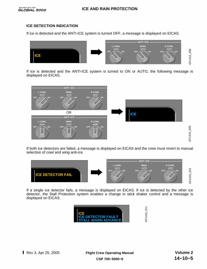
ICE DETECTION INDICATION
If ice is detected and the ANTI-ICE system is turned OFF, a message is displayed on EICAS.
GF
1410
_008
ICE
AUTOAUTOOFF ON
AUTOR COWLWINGL COWL
ANTI−ICE
OFF ON OFF ON
If ice is detected and the ANTI-ICE system is turned to ON or AUTO, the following message isdisplayed on EICAS.
GF
1410
_009
OR ICE
AUTOAUTOOFF ON
AUTOR COWLWINGL COWL
ANTI−ICE
AUTOAUTOOFF ON
AUTOR COWLWINGL COWL
ANTI−ICE
OFF ON
OFF ONAUTO
OFF ON
OFF ON
If both ice detectors are failed, a message is displayed on EICAS and the crew must revert to manualselection of cowl and wing anti-ice.
GF
1410
_010
ICE DETECTOR FAIL
AUTOAUTOOFF ON
AUTOR COWLWINGL COWL
ANTI−ICE
OFF ON OFF ON
If a single ice detector fails, a message is displayed on EICAS. If ice is detected by the other icedetector, the Stall Protection system enables a change in stick shaker control and a message isdisplayed on EICAS.
GF
1410
_011
ICEICE DETECTOR FAULTSTALL WARN ADVANCE
ICE AND RAIN PROTECTION
Rev 3, Apr 25, 2005 Flight Crew Operating Manual
CSP 700−5000−6
Volume 214−10−5

PNEUMATIC ANTI-ICING
Engine bleed air is used for the following systems:
COWL ANTI-ICING (CAI)
The cowl anti-icing system is used to prevent formation of ice on the nose cowl of the engine. Thecowl leading edge uses hot engine bleed air from the low pressure compressor 5th stage to heat thenose cowl. The bleed air is ducted through a spray ring and exhausts to atmosphere, through an exitgrill.
Engine Spinner
The engine spinner point is made of soft rubber which will distort during engine running and iceaccumulation and will shed any ice buildup. The rear of the spinner and the fan blades usecentrifugal force to shed ice after start up, to prevent ice accumulation during engine running.
X
SPRAY RING
EXHAUST DUCT
EXHAUST
NOSE COWL LIP
SPINNER
FAN BLADES
AIR INLET COWL
SPINNER POINT
BLEED AIRSUPPLY DUCT
NOSE COWL LIP
GF
1410
_012
AND SPINNER
Cowl Anti-Ice Valves
There are two Cowl Anti-Ice Valves (CAIV), which control the flow of engine bleed air to the cowlducting. The CAIVs are spring-loaded open, pneumatically operated, electrically controlled,pressure regulating and shutoff valves, that are controlled by signals from the ice detectingsystem. They are either fully open or fully closed.
ICE AND RAIN PROTECTION
Rev 3, Apr 25, 2005Flight Crew Operating Manual
CSP 700−5000−6
Volume 214−10−6

CAI OPERATION
When the L and/ or R COWL selector is selected to AUTO and ice is detected, the ice detectionsystem sends a signal to a relay in the ANTI-ICE panel, that commands the anti-ice valves open. Ifan ice detector fails, the other detector will activate both cowl anti-ice valves in AUTO mode. A statusmessage is displayed on EICAS.
RH ICE DETECTOR
LH ICE DETECTOR
LOW PRESS PORT
HIGH PRESS PORT
CAIV
SPRAY RING
SYNOPTIC
LP
HP
GF
1410
_013
HP
LP
L−R COWL A/ICE AUTO
AUTOOFF ON
R COWL
AUTOOFF ON
L COWL
Cowl anti-icing can be manually selected to ON, in which case the CAIVs will open, independent ofthe ice detection system and a status message is displayed. Whenever cowl anti-ice is activated(AUTO or ON), a CAI icon will be displayed on the EICAS page.
73.373.3
789789
N1
ITT
CAICAI
INDICATIONCAI
LP
HP
GF
1410
_014
L−R COWL A/ICE ON
EICAS
AUTOOFF ON
L COWLAUTO
OFF ON
L COWL
ICE AND RAIN PROTECTION
Rev 3, Apr 25, 2005 Flight Crew Operating Manual
CSP 700−5000−6
Volume 214−10−7

WING ANTI-ICING (WAI)
The wing anti-icing system is used to prevent formation of ice on the leading edge of the wing. Thewing leading edge uses hot engine bleed air from either the 5th stage or the high pressurecompressor 8th stage, of the bleed air system.
HPGROUND AIR SUPPLY
R WINGA/I VALVE
CROSSBLEEDVALVE
L WINGA/I VALVE
WING CROSSBLEED VALVE
TEMPERATURE SENSORS
ICE DETECTOR
LOWPRESSPORT
HIGHPRESS PORT
L ATSVALVE
HIGHPRESS VALVE
PRSOV
COWL ANTI−ICE
L COWLA/I VALVE
R ATS VALVE
R COWL A/I VALVE
R AIRTURBINESTARTER
APU
L AIRTURBINESTARTER
BMC 1 BMC 2CONT
CHMONCH
CONTCH
MONCH
DAUDAU
L AIR CONDITIONING
GF
1410
_015
Wing Anti-Ice Valves (WAIV)
Two wing anti-ice valves are electrically controlled, pneumatically operated, spring loaded closed,modulating shutoff valves. The ice detector system will send a signal to the BMC to activate thewing anti-ice system. The temperature sensor, located in the fixed leading edge, provides a signalto the control channel of the BMC, which drives the WAIVs open or closed. The other temperaturesensors, located in the fixed leading edge, provide a signal to a monitoring channel in the BMC.One channel controls and the other channels act as a monitor but can assume control in the eventof a failure of the control sensor. In the event of complete failure of sensors on one side, theserviceable control sensor on the opposite side, will control the WAIVs.
ICE AND RAIN PROTECTION
Rev 3, Apr 25, 2005Flight Crew Operating Manual
CSP 700−5000−6
Volume 214−10−8
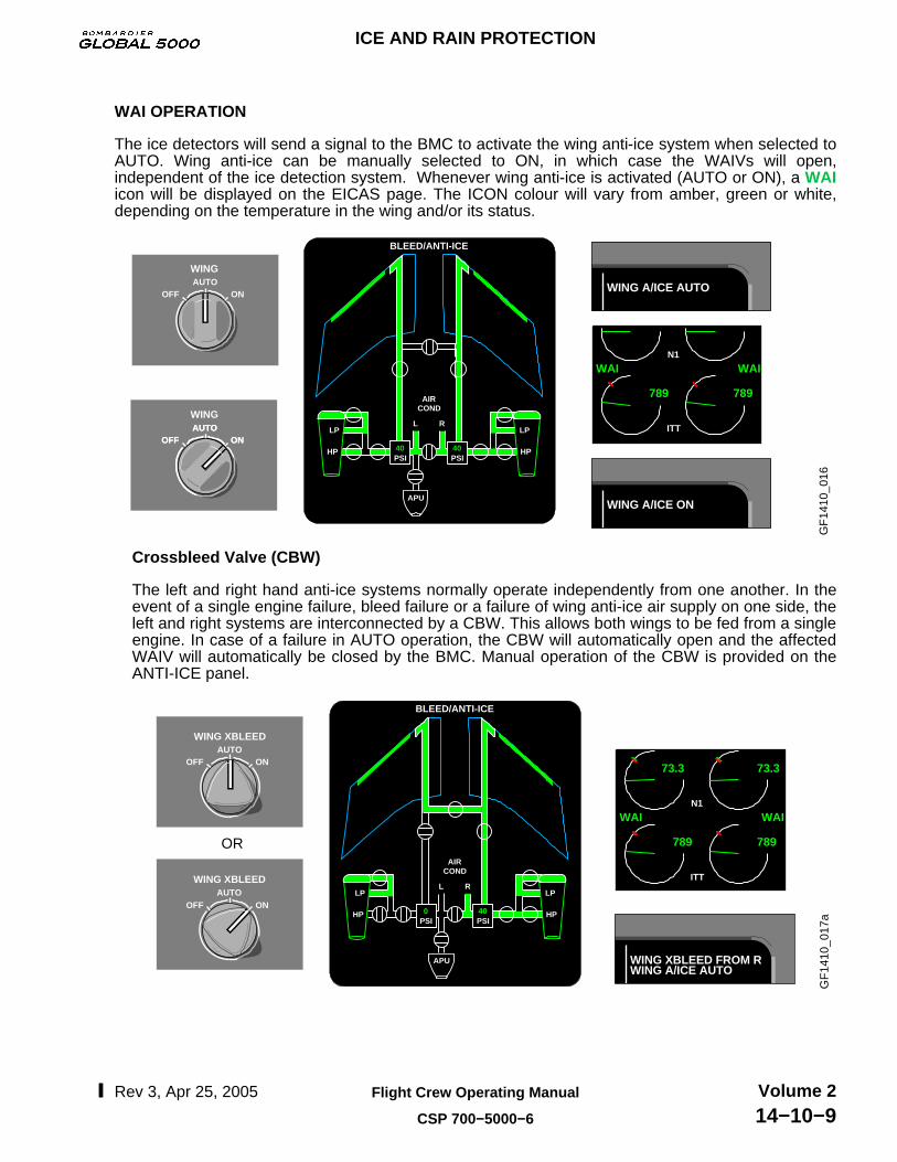
WAI OPERATION
The ice detectors will send a signal to the BMC to activate the wing anti-ice system when selected toAUTO. Wing anti-ice can be manually selected to ON, in which case the WAIVs will open,independent of the ice detection system. Whenever wing anti-ice is activated (AUTO or ON), a WAIicon will be displayed on the EICAS page. The ICON colour will vary from amber, green or white,depending on the temperature in the wing and/or its status.
GF
1410
_016
LP
HP
L R
APU
HP
LP
CONDAIR
BLEED/ANTI-ICE
WING A/ICE AUTO
789789
N1
ITT
WAIWAI
40PSI
WING A/ICE ON
AUTOOFF ON
WING
WINGAUTO
OFF ONAUTO
OFF ON40PSI
Crossbleed Valve (CBW)
The left and right hand anti-ice systems normally operate independently from one another. In theevent of a single engine failure, bleed failure or a failure of wing anti-ice air supply on one side, theleft and right systems are interconnected by a CBW. This allows both wings to be fed from a singleengine. In case of a failure in AUTO operation, the CBW will automatically open and the affectedWAIV will automatically be closed by the BMC. Manual operation of the CBW is provided on theANTI-ICE panel.
73.373.3
789789
N1
ITT
WAIWAIG
F14
10_0
17a
LP
HP
L R
APU
HP
LP
CONDAIR
BLEED/ANTI-ICE
0PSI
WING XBLEED FROM R
40PSI
WING A/ICE AUTO
OR
AUTOOFF ON
WING XBLEED
AUTOWING XBLEED
OFF ON
ICE AND RAIN PROTECTION
Rev 3, Apr 25, 2005 Flight Crew Operating Manual
CSP 700−5000−6
Volume 214−10−9

WAI FAILURE INDICATIONS
The WAI failure indications are as follows:
Wing Anti-Ice Overheat
If there is an overheat in the wing anti-ice system, a message is displayed on EICAS.
Turn WING ANTI-ICE OFF789789
N1
ITT
WAIWAI
GF
1410
_018
a
BLEED/ANTI-ICE
WING A/ICE OVHT
AUTOOFF ON
WING
AUTOOFF ON
WING
Wing Anti-Ice Fail
If wing anti-ice is failed, a message is displayed on EICAS. If ice is detected during this failurecondition, the stall warning trigger points are advanced automatically. Ensure rpm (N2) is above76% may make this amber message diappear.
NOTEIf ice is detected, the stall warning trigger points are advanced automatically. For more information on stall protection, see Chapter 10, FLIGHT CONTROLS. G
F14
10_0
19
ICEL−R WING A/ICE FAILSTALL WARN ADVANCE
ICE AND RAIN PROTECTION
Rev 3, Apr 25, 2005Flight Crew Operating Manual
CSP 700−5000−6
Volume 214−10−10
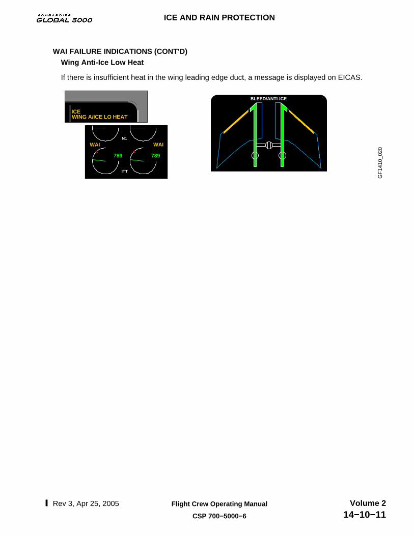
WAI FAILURE INDICATIONS (CONT'D)Wing Anti-Ice Low Heat
If there is insufficient heat in the wing leading edge duct, a message is displayed on EICAS.
789789
N1
ITT
WAIWAI
GF
1410
_020
AIR
BLEED/ANTI-ICE
ICEWING A/ICE LO HEAT
ICE AND RAIN PROTECTION
Rev 3, Apr 25, 2005 Flight Crew Operating Manual
CSP 700−5000−6
Volume 214−10−11
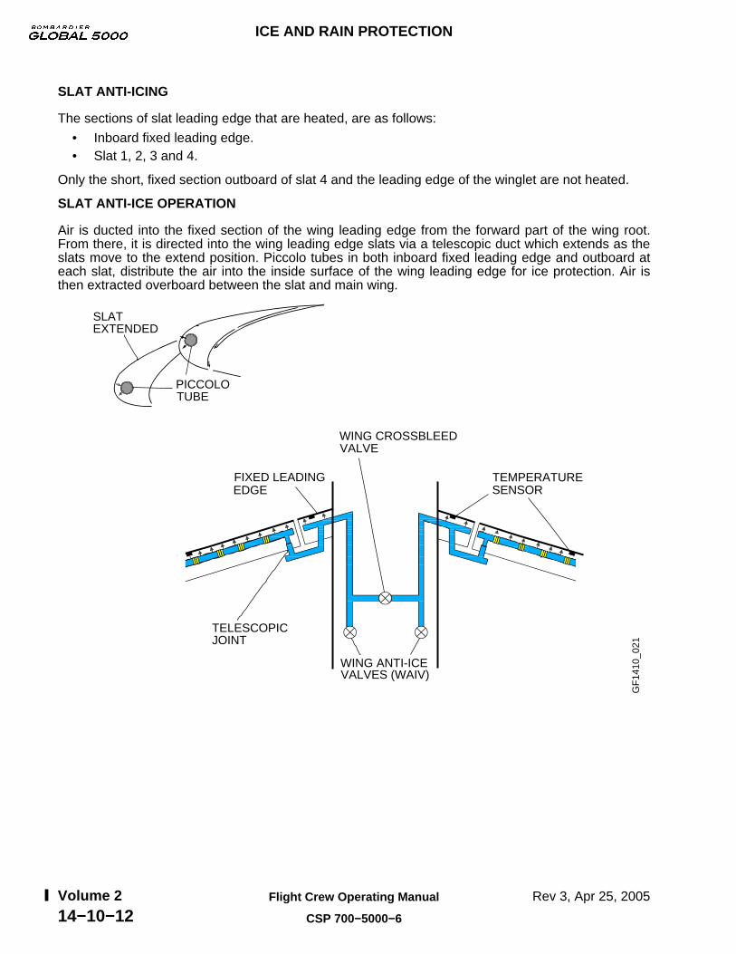
SLAT ANTI-ICING
The sections of slat leading edge that are heated, are as follows:
• Inboard fixed leading edge.• Slat 1, 2, 3 and 4.
Only the short, fixed section outboard of slat 4 and the leading edge of the winglet are not heated.
SLAT ANTI-ICE OPERATION
Air is ducted into the fixed section of the wing leading edge from the forward part of the wing root.From there, it is directed into the wing leading edge slats via a telescopic duct which extends as theslats move to the extend position. Piccolo tubes in both inboard fixed leading edge and outboard ateach slat, distribute the air into the inside surface of the wing leading edge for ice protection. Air isthen extracted overboard between the slat and main wing.
TEMPERATURE SENSOR
FIXED LEADING EDGE
WING CROSSBLEED VALVE
WING ANTI-ICE VALVES (WAIV)
SLATEXTENDED
PICCOLO TUBE
TELESCOPIC JOINT
GF
1410
_021
ICE AND RAIN PROTECTION
Rev 3, Apr 25, 2005Flight Crew Operating Manual
CSP 700−5000−6
Volume 214−10−12

ELECTRICAL ANTI-ICING
Electrical power is used to operate the following:
AIR DATA PROBES AND SENSORS
The air data probes and sensors anti-ice system prevents ice accumulation on the probes andsensors, which could lead to incorrect data transmission to the Air Data Computers (ADC).
The air data probes and sensors anti-ice system is controlled automatically by two Heater/BrakeTemperature Monitoring Units (HBMU).
TAT1
TAT2BTMS3
BTMS1
BTMS4
BTMS2
YD HEATER 1
YD HEATER 2
PS 1PS 3
PS STANDBY PS 2
AOA 2
AOA 1
TAT 3
PS − PITOT/STATICAOA − ANGLE OF ATTACKBTMS − BRAKE TEMPERATURE MONITOR SYSTEMTAT − TOTAL AIR TEMPERATUREYD −YAW DAMPER
HBMU1
HBMU2
GF
1410
_022
HBMU
HBMU 1 controls AOA 1, PS 1, PS 3, TAT 1 and YD Heater 1 and monitors BTMS 1 and BTMS 2.
HBMU 2 controls AOA 2, PS 2, PS Standby, TAT 2, TAT 3 and YD Heater 2 and monitors BTMS3 and monitors BTMS 3 and BTMS 4.
The HBMUs also monitor brake temperature data. The data sent by the Brake TemperatureMonitoring System (BTMS), which incorporates four sensors, installed in the brake housings,provides excessive brake temperature warning to EICAS (For more information see Chapter 15,LANDING GEAR). The HBMU also controls heat to Yaw Damper (YD) actuators, to ensure thatthe standby YD actuator is heated. (For more information see Chapter 10, FLIGHT CONTROLS).
ICE AND RAIN PROTECTION
Rev 3, Apr 25, 2005 Flight Crew Operating Manual
CSP 700−5000−6
Volume 214−10−13
AIR DATA PROBES AND SENSORS (CONT'D)HBMU (Cont’d)
The HBMU receives data from various airplane systems via the Data Acquisition Units (DAU) tocontrol the heaters. The systems that send data to the DAUs are:
• Electronic Engine Controllers (EEC), for the “all heaters off” logic and for TAT probe on/offlogic.
• Fault Warning Computer (FWC), regarding which ADC is selected for cockpit display.• Automatic Flight Control System (AFCS), regarding which Yaw Damper is in use, for YD
heater control logic.• Air Data Computers (ADC) to provide TAT information to control heat to the Yaw Dampers
and airspeed information for “all heaters off” logic.• Electrical Load Management System (EMS), provides BUS status and ADG information for
heater control logic.• Weight On Wheels (WOW), for “all heaters off” logic and for TAT probe on/off logic.
The heaters are driven to the indicated ON/OFF state based on the following logic:
• AOA 1 Heater Off − AC ESS BUS unpowered and WOW.• AOA 2 Heater Off − AC ESS BUS unpowered and AC BUS 1 unpowered and WOW.• PS 1 Heater Off − ADG deployed and ADC 1 not selected or AC ESS BUS unpowered
and AC BUS 1 unpowered.• PS 2 Heater Off − AC BUS 2 unpowered.• PS 3 Heater Off − ADG deployed and ADC 3 not selected or AC ESS BUS unpowered.• PS STBY Heater Off − AC ESS BUS unpowered.• TAT 1 Heater Off − WOW and LH engine Off.• TAT 2 Heater Off − WOW and RH engine Off.• TAT 3 Heater Off − WOW or AC BUS 3 unpowered.• YD 1 Heater On − TAT <−40°C and Yaw Damper 1 not engaged.• YD 2 Heater On − TAT <−40°C and Yaw Damper 2 not engaged.
The “all heaters off” control function, turns OFF all heaters and overrides the above heater on/offlogic equations when :
• L and R engine not running and/or,• WOW and/or,• airspeed less than 50 knots.
ICE AND RAIN PROTECTION
Rev 3, Apr 25, 2005Flight Crew Operating Manual
CSP 700−5000−6
Volume 214−10−14

AIR DATA PROBES AND SENSORS (CONT'D)Probes
There are four Pitot-Static (PS) probes on the side of the fuselage. They supply pitot and staticpressure to the air data computers and standby instruments. Heater elements are installed in thePS heads and mounting bases.
There are three Total Air Temperature (TAT) probes, one on the fuselage and one each in theengine inlets.
There are two AOA probes, mounted on the fuselage, one on either side.
PS STANDBY
PS 1
PS 3PSSTANDBY
PS 2
TAT 3
TAT 3PS 2
TAT 2
TO
P V
IEW
ENGINE INLET
TAT 1/2
AOA 2AOA 1
AOA 2
PS 3
PS 1TAT 1
AOA 1
GF
1410
_023
PROBE
The current being drawn by the heater is measured and a heater fault is generated if the currentdrawn is less than the minimum required by the particular probe. The fault is then transmitted toEICAS.
GF
1410
_024
L−R AOA HEAT FAILPITOT 1−2−3 HT FAILSTBY PITOT HT FAILTAT 1−2 FAIL
ICE AND RAIN PROTECTION
Rev 3, Apr 25, 2005 Flight Crew Operating Manual
CSP 700−5000−6
Volume 214−10−15
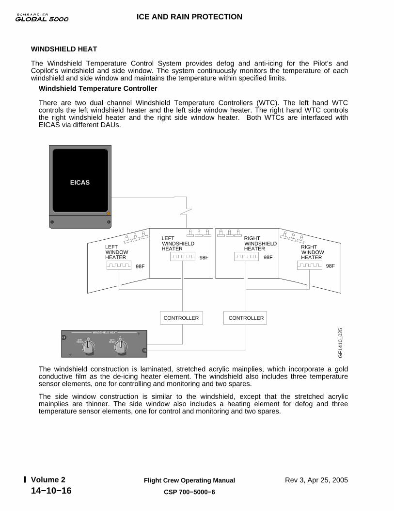
WINDSHIELD HEAT
The Windshield Temperature Control System provides defog and anti-icing for the Pilot’s andCopilot’s windshield and side window. The system continuously monitors the temperature of eachwindshield and side window and maintains the temperature within specified limits.
Windshield Temperature Controller
There are two dual channel Windshield Temperature Controllers (WTC). The left hand WTCcontrols the left windshield heater and the left side window heater. The right hand WTC controlsthe right windshield heater and the right side window heater. Both WTCs are interfaced withEICAS via different DAUs.
GF
1410
_025
EICAS
LEFTWINDOWHEATER
LEFTWINDSHIELDHEATER
RIGHTWINDSHIELDHEATER RIGHT
WINDOWHEATER
98F
98F 98F
98F
CONTROLLER CONTROLLER
R
WINDSHIELD HEAT
ONOFF/RESET
LONOFF/
RESET
The windshield construction is laminated, stretched acrylic mainplies, which incorporate a goldconductive film as the de-icing heater element. The windshield also includes three temperaturesensor elements, one for controlling and monitoring and two spares.
The side window construction is similar to the windshield, except that the stretched acrylicmainplies are thinner. The side window also includes a heating element for defog and threetemperature sensor elements, one for control and monitoring and two spares.
ICE AND RAIN PROTECTION
Rev 3, Apr 25, 2005Flight Crew Operating Manual
CSP 700−5000−6
Volume 214−10−16
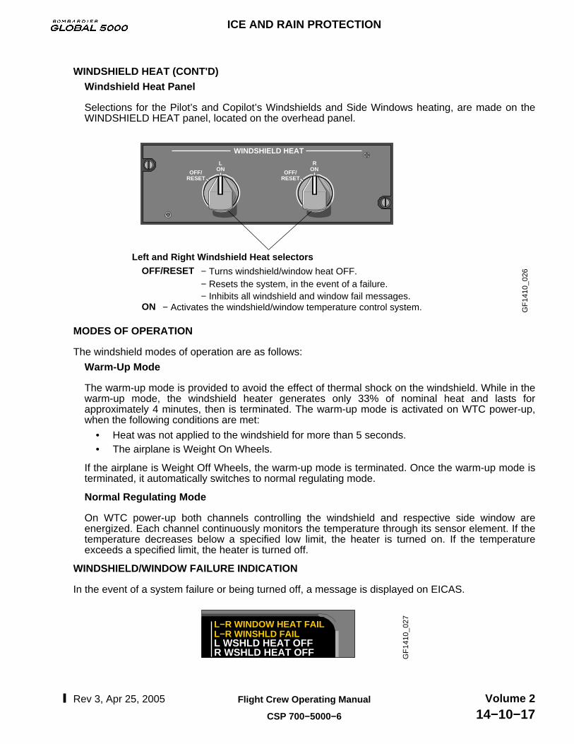
WINDSHIELD HEAT (CONT'D)Windshield Heat Panel
Selections for the Pilot’s and Copilot’s Windshields and Side Windows heating, are made on theWINDSHIELD HEAT panel, located on the overhead panel.
− Resets the system, in the event of a failure. − Inhibits all windshield and window fail messages.
Left and Right Windshield Heat selectors
GF
1410
_026 OFF/RESET
ON
− Turns windshield/window heat OFF.
− Activates the windshield/window temperature control system.
R
WINDSHIELD HEAT
ONOFF/RESET
LONOFF/
RESET
MODES OF OPERATION
The windshield modes of operation are as follows:
Warm-Up Mode
The warm-up mode is provided to avoid the effect of thermal shock on the windshield. While in thewarm-up mode, the windshield heater generates only 33% of nominal heat and lasts forapproximately 4 minutes, then is terminated. The warm-up mode is activated on WTC power-up,when the following conditions are met:
• Heat was not applied to the windshield for more than 5 seconds.• The airplane is Weight On Wheels.
If the airplane is Weight Off Wheels, the warm-up mode is terminated. Once the warm-up mode isterminated, it automatically switches to normal regulating mode.
Normal Regulating Mode
On WTC power-up both channels controlling the windshield and respective side window areenergized. Each channel continuously monitors the temperature through its sensor element. If thetemperature decreases below a specified low limit, the heater is turned on. If the temperatureexceeds a specified limit, the heater is turned off.
WINDSHIELD/WINDOW FAILURE INDICATION
In the event of a system failure or being turned off, a message is displayed on EICAS.
GF
1410
_027L−R WINDOW HEAT FAIL
L−R WINSHLD FAILL WSHLD HEAT OFFR WSHLD HEAT OFF
ICE AND RAIN PROTECTION
Rev 3, Apr 25, 2005 Flight Crew Operating Manual
CSP 700−5000−6
Volume 214−10−17
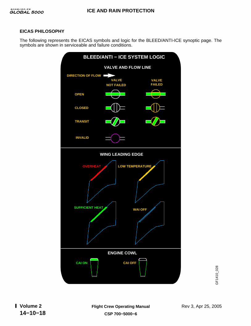
EICAS PHILOSOPHY
The following represents the EICAS symbols and logic for the BLEED/ANTI-ICE synoptic page. Thesymbols are shown in serviceable and failure conditions.
BLEED/ANTI − ICE SYSTEM LOGIC
VALVE AND FLOW LINE
OPEN
VALVE
NOT FAILED
CLOSED
TRANSIT
INVALID
VALVE FAILED
DIRECTION OF FLOW
LOW TEMPERATURE
WAI OFF
WING LEADING EDGE
OVERHEAT
SUFFICIENT HEAT
ENGINE COWL
CAI OFFCAI ON
GF
1410
_028
ICE AND RAIN PROTECTION
Rev 3, Apr 25, 2005Flight Crew Operating Manual
CSP 700−5000−6
Volume 214−10−18

ICE AND RAIN EICAS MESSAGES
L−R WINDOW HEAT FAILIndicates that the respective window heater temperature controller has failed.
ICEIndicates that ice has been detected and one or the other system is OFF.
WING A/ICE OVHTIndicates that an overtemperature has been detected in the wing anti-ice system.
L−R WING A/ICE FAILIndicates that the wing anti-ice valve is not in the selected position.
PITOT 1−2−3 HT FAILIndicates that the respective pitot heater has failed.
WING A/ICE LEAKIndicates that a bleed leak has been detected in the wing anti-ice system.
STBY PITOT HEAT FAILIndicates that the standby pitot heater has failed.
ICE DETECTOR FAILIndicates the loss of both ice detectors.
L−R COWL A/ICE FAILIndicates that the cowl anti-ice valve is not in the selected position.
L−R WSHLD HEAT FAILIndicates that the respective windshield heater temperature controller has failed.
L−R AOA HEAT FAILIndicates that respective AOA has failed.
WING A/ICE LO HEATIndicates that there is insufficient heat in the wing leading edge duct.
GF
1410
_029
a
R AOA HEAT FAIL
ICE DETECTOR FAIL L AOA HEAT FAIL
ICE
L WINDOW HEAT FAIL
L COWL A/ICE FAILR COWL A/ICE FAIL
R WING A/ICE FAIL
R WINDOW HEAT FAILL WING A/ICE FAIL
L WSHLD HEAT FAILR WSHLD HEAT FAILPITOT 1 HT FAIL
WING A/ICE OVHT
PITOT 2 HT FAILPITOT 3 HT FAILSTBY PITOT HT FAILWING A/ICE LEAKWING A/ICE LO HEAT
ICE AND RAIN PROTECTION
Rev 3, Apr 25, 2005 Flight Crew Operating Manual
CSP 700−5000−6
Volume 214−10−19

ICE AND RAIN EICAS MESSAGES (CONT'D)
ICE DETECTOR FAULTIndicates that there is a loss of one ice detector.
L−R PROBE MON FAILIndicates that the heater status of the probes and associated systems is not verified.
TAT HT 1−2−3 FAILIndicates that the respective TAT heater has failed.
WING A/ICE FAULTIndicates loss of redundancy on wing anti-ice system.
ICEIndicates that cowl or wing anti-icing has been detected with anti-ice systems ON.
WING A/ICE SENSORIndicates loss of both outboard wing anti-ice temperature sensors.
L−R COWL A/ICE FAULTIndicates that there is a loss of the affected cowl anti-ice.
YD HEAT 1−2 FAILIndicates that the respective yaw damper heater has failed.
GF
1410
_030
a
R PROBE MON FAILL PROBE MON FAIL
TAT HT 3 FAIL
TAT HT 1 FAILTAT HT 2 FAIL
WING A/ICE FAULTWING A/ICE SENSOR
R COWL A/ICE FAULT
TAT 3 FAIL
TAT 1 FAILTAT 2 FAIL
ICE DETECTOR FAULT L COWL A/ICE FAULT
ICE
YD HEAT 1 FAILYD HEAT 2 FAIL
TAT 1−2−3 FAILIndicates that the respective TAT has failed.
ICE AND RAIN PROTECTION
Rev 3, Apr 25, 2005Flight Crew Operating Manual
CSP 700−5000−6
Volume 214−10−20
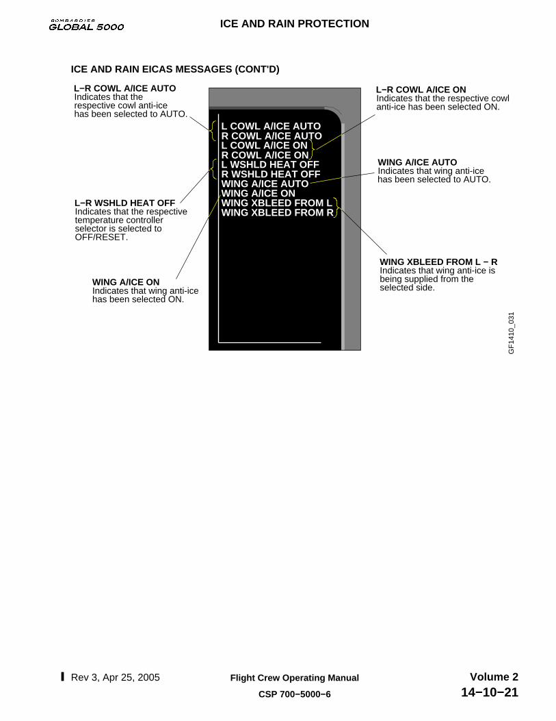
ICE AND RAIN EICAS MESSAGES (CONT'D)
L−R COWL A/ICE ONIndicates that the respective cowl anti-ice has been selected ON.
L−R WSHLD HEAT OFFIndicates that the respective temperature controller selector is selected to OFF/RESET.
WING XBLEED FROM L − R Indicates that wing anti-ice isbeing supplied from theselected side.
WING A/ICE AUTOIndicates that wing anti-ice has been selected to AUTO.
WING A/ICE ONIndicates that wing anti-ice has been selected ON.
L−R COWL A/ICE AUTOIndicates that the respective cowl anti-ice has been selected to AUTO.
GF
1410
_031
L COWL A/ICE AUTOR COWL A/ICE AUTOL COWL A/ICE ONR COWL A/ICE ONL WSHLD HEAT OFFR WSHLD HEAT OFFWING A/ICE AUTOWING A/ICE ONWING XBLEED FROM LWING XBLEED FROM R
ICE AND RAIN PROTECTION
Rev 3, Apr 25, 2005 Flight Crew Operating Manual
CSP 700−5000−6
Volume 214−10−21

ICE AND RAIN PROTECTION
Rev 3, Apr 25, 2005Flight Crew Operating Manual
CSP 700−5000−6
Volume 214−10−22
THIS PAGE INTENTIONALLY LEFT BLANK

CB - ICE SYSTEM
GF
1420
_001
STAT SYS BUS PREV CNTL TESTPAGE
NEXTPAGE
EMERCNTL
BUS
CIRCUIT BREAKER − SYSTEM 2/2
SYSTEMCIRCUIT BREAKER
HYD
ICE
IND/RECORD
LDG GEAR
LIGHTS
NAV
OIL
OXYGEN
THRUST REV
BRT
BATT
HBMU 2
L AOA HEAT
L WINDOW HEAT
INHBMU 1
IN
IN
IN
IN
BATT
DC ESS
AC ESS
L COWL A/ICE VLV
AC ESS
AC ESS
IN
AC 1
L WIING A/ICE CTL
L WISHLD HEAT 1
PITOT 1 HT A
PITOT 1 HT B
INL WINDOW HEAT CTL
IN
IN
IN
IN
DC ESS
DC ESS
AC 1
L WSHLD HEAT 2
AC 1
AC ESS
IN
PITOT 3 HT
R AOA HEAT A
R COWL A/ICE VLV
R ICE DETECTOR
INPITOT 2 HT
IN
IN
IN
IN
AC 2
AC ESS
AC 1
AC ESS R AOA HEAT B
BATT
AC 1
IN
L ICE DETECTOR
CCBP
CCBP
CCBP
CCBP
CCBP
CCBP
CCBP
CCBP
CCBP
CCBP
CCBP
CCBP
1/5CB − ICE SYSTEM
2/5CB − ICE SYSTEM
3/5CB − ICE SYSTEM
R WINDOW HEAT CTL
R WING A/ICE CTL
R WSHLD HEAT 1
R WSHLD HEAT 2
STBY PITOT HT
INR WINDOW HEAT
IN
IN
IN
IN
AC 2
DC 1
DC ESS
AC 3
AC 3
AC ESS IN
TAT HT 2
TAT HT 3
WAI XBLEED CTL
WAI XBLEED VLV
INTAT HT 1
IN
IN
IN
IN
AC ESS
AC ESS
AC 3
DC ESS
DC ESS
CCBP
CCBP
CCBP
CCBP
CCBP
CCBP
CCBP
CB − ICE SYSTEM 4/5
CB − ICE SYSTEM 5/5
ICE AND RAIN PROTECTION
EMS CIRCUIT PROTECTION
Rev 2A, Apr 11, 2005 Flight Crew Operating Manual
CSP 700−5000−6
Volume 214−20−1

ICE AND RAIN PROTECTION
EMS CIRCUIT PROTECTION
Rev 2A, Apr 11, 2005Flight Crew Operating Manual
CSP 700−5000−6
Volume 214−20−2
THIS PAGE INTENTIONALLY LEFT BLANK
![Ice & Rain Protection - SmartCockpit...Airbus A319-320-321 [Ice & Rain Protection] Page 1](https://static.fdocuments.in/doc/165x107/60d9e1cdd5a0e50edc623935/ice-rain-protection-smartcockpit-airbus-a319-320-321-ice-rain.jpg)