ICC Vapor Perm Submit -...
35
2016 ICC Annual Conference Education Program Kansas City, MO 1 Vapor Permeability of Materials & Assemblies – Determining the When and Where of Vapor Retarders Dr. Theresa Weston Senior Research Fellow DuPont Protective Solutions Learning Objectives • Understand IBC and IRC vapor retarder requirements and their development • Understand vapor permeability test methods • Learn vapor permeability ranges for common building materials • Learn key considerations of hygrothermal analysis
Transcript of ICC Vapor Perm Submit -...

2016 ICC Annual Conference Education ProgramKansas City, MO 1
Vapor Permeability of Materials &
Assemblies – Determining the When
and Where of Vapor Retarders
Dr. Theresa Weston
Senior Research Fellow
DuPont Protective Solutions
Learning Objectives
• Understand IBC and IRC vapor retarder requirements and their development
• Understand vapor permeability test methods
• Learn vapor permeability ranges for common building materials
• Learn key considerations of hygrothermal analysis

2016 ICC Annual Conference Education ProgramKansas City, MO 2
IBC/IRC Vapor Permeability Requirements
• Classes of vapor retarders
• Where vapor retarders are required
• Where vapor retarders are restricted
• Where vapor permeable materials are required
IBC
VAPOR RETARDER CLASS. A measure of a material or assembly’s ability to limit the amount of moisture that passes through that material or assembly.
Vapor retarder class shall be defined using the desiccant method of ASTM E 96 as follows:
Class I: 0.1 perm or less.
Class II: 0.1 < perm <1.0 perm.
Class III: 1.0 < perm <10 perm.
IRC
VAPOR RETARDER CLASS. A measure of the ability of a material or assembly to limit the amount of moisture that passes through that material or assembly.
Vapor retarder class shall be defined using the desiccant method with Procedure A of ASTM E 96 as follows:
Class I: 0.1 perm or less
Class II: 0.1 < perm < 1.0 perm
Class III: 1.0 < perm < 10 perm
IBC/IRC Requirements: Classes of Vapor Retarders
Requires testing under dessicant method
25%RH

2016 ICC Annual Conference Education ProgramKansas City, MO 3
IBC/IRC Requirements: Classes of Vapor Retarders
IBC
1405.3.3 Material vapor retarder class. The vapor retarder class shall be based on the manufacturer’s certified testing or a tested assembly. The following shall be deemed to meet the class specified:
Class I: Sheet polyethylene, nonperforatedaluminum foil with a perm rating of less than or equal to 0.1.
Class II: Kraft-faced fiberglass batts or paint with a perm rating greater than 0.1 and less than or equal to 1.0.
Class III: Latex or enamel paint with a perm rating of greater than 1.0 and less than or equal to 10.0.
IRC
R702.7.2 Material vapor retarder class. The vapor retarder class shall be based on the manufacturer’s certified testing or a tested assembly.
The following shall be deemed to meet the class specified:
Class I: Sheet polyethylene, unperforated aluminum foil.
Class II: Kraft-faced fiberglass batts.
Class III: Latex or enamel paint.
IBC/IRC Requirements: Classes of Vapor Retarders
IBC
VAPOR PERMEABLE MEMBRANE. The property ofhaving a moisture vapor permeance rating of 5 perms (2.9 ×10⁻¹⁰ kg/Pa × s × m2) or greater, when tested in accordance with the desiccant method using Procedure A of ASTM E 96.
A vapor permeable material permits the passage of moisture vapor.
IRC
VAPOR PERMEABLE. The property of having a
moisture vapor permeance rating of 5 perms (2.9 x 10⁻¹⁰ kg/ Pa · s · m2) or greater, where tested in accordance with the desiccant method using Procedure A of ASTM E 96.
A vapor permeable material permits the passage of moisture vapor.
Vapor PermeableClass III Vapor Retarder
1perm 5perm 10 perm

2016 ICC Annual Conference Education ProgramKansas City, MO 4
Where vapor retarders are required?
The IBC & IRC have permeability requirements for • Roof / Attic assemblies• Wall assemblies• Floor / crawlspace
assemblies
International Residential Code
(IRC-2015)Requirements

2016 ICC Annual Conference Education ProgramKansas City, MO 5
IRC-2015 R703.1.1 Water resistance. The exterior wall envelope shall be designed and constructed in a manner that prevents the accumulation of water within the wall assembly by providing a water-resistant barrier behind the exterior veneer as required by Section R703.2 and a means of draining to the exterior water that enters the assembly. Protection against condensation in the exterior wall assembly shall be provided in accordance with Section R702.7 of this code.
R702.7 Vapor retarders. Class I or II vapor retarders are required on the interior side of frame walls in Climate Zones 5, 6, 7, 8 and Marine 4.
Exceptions:
1. Basement walls.
2. Below-grade portion of any wall.
3. Construction where moisture or its freezing will not damage the materials.
Vapor retarders required to control vapor from condensing in the wall assembly
IRC-2015 R703.1.1 Water resistance. The exterior wall envelope shall be designed and constructed in a manner that prevents the accumulation of water within the wall assembly by providing a water-resistant barrier behind the exterior veneer as required by Section R703.2 and a means of draining to the exterior water that enters the assembly. Protection against condensation in the exterior wall assembly shall be provided in accordance with Section R702.7 of this code.
R702.7 Vapor retarders. Class I or II vapor retarders are required on the interior side of frame walls in Climate Zones 5, 6, 7, 8 and Marine 4.
Exceptions:
1. Basement walls.
2. Below-grade portion of any wall.
3. Construction where moisture or its freezing will notdamage the materials.

2016 ICC Annual Conference Education ProgramKansas City, MO 6
Where are interior vapor retarders required?
2003: Above White Line
2006: Above Red Line
Effect of interior vapor barriers (Zone 5)
Effect of Vapor Barrier Presence on OSB Moisture Content
60
80
100
120
140
160
180
0 5000 10000 15000 20000 25000
Time (hrs)
OS
B W
ater
Co
nte
nt
(kg
/m3)
2x4, no vapor barrier 2x4, w/ vapor barrier 2x6, no vapor barrier
2x6, w/ vapor barrier 2x4 + XPS, no vapor barrier 2x4 + XPS, w/ vapor barrier

2016 ICC Annual Conference Education ProgramKansas City, MO 7
CASE 1 - Results
Figure 6: SBPO (w/o Internal Vapor Barrier) Vapor Diffusion Performance
(Starting Jan 1)
0.00
0.50
1.00
1.50
2.00
2.50
3.00
3.50
4.00
0 100 200 300 400 500 600 700 800
Days
To
tal
Wal
l M
ois
ture
Le
vel
(kg
/m2 )
SBPO no/Int VB - Chicago SBPO no/Int VB - St Louis SBPO no/Int VB - New Orleans
IRC-2015 R702.7.1 Class III vapor retarders. Class III vapor retarders shall be permitted where any one of the conditions in Table R702.7.1 is met.
R702.7.3 Minimum clear airspaces and vented openings for vented cladding. For the purposes of this section, vented cladding shall include the following minimum clear airspaces. Other openings with the equivalent vent area shall be permitted.
1. Vinyl lap or horizontal aluminum siding applied over a weather-resistive barrier as specified in Table R703.3(1).
2. Brick veneer with a clear airspace as specified in Table R703.8.4.
3. Other approved vented claddings.
2016 ICC Annual Conference Education ProgramKansas City, MO 8
Class III Vapor Retarders allowed in cold climates in some wall systems:
VENTILATED CLADDING
Condensation plane of concern
EXTERIOR INSULATION
Condensation plane of concern above dewpoint
Includes vinyl and brick with airspace
Specific sheathing R-Values dependent on climate.
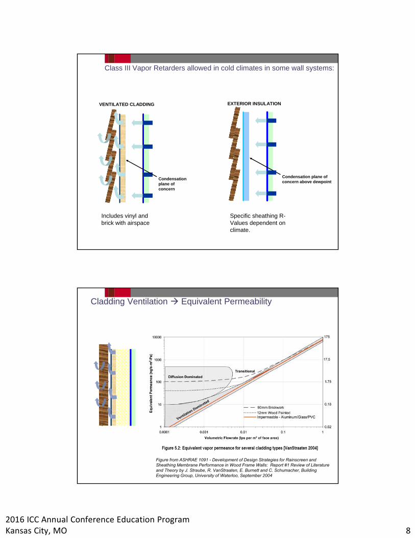
Cladding Ventilation Equivalent Permeability
Figure from ASHRAE 1091 - Development of Design Strategies for Rainscreen and Sheathing Membrane Performance in Wood Frame Walls: Report #1 Review of Literature and Theory by J. Straube, R. VanStraaten, E. Burnett and C. Schumacher, Building Engineering Group, University of Waterloo, September 2004

2016 ICC Annual Conference Education ProgramKansas City, MO 9
Vapor Diffusion Balance Wetting and Drying
“Ventilation of walls (e.g. typical loose-applied vinyl siding or brick veneers with clear large vent openings top and bottom) encourages faster drying and significantly reduces the impact of solar-driven inward vapor drive condensation.”-- Straube, et. al “Field Studies of Ventilation Drying”, presented at the Buildings IX Conference, December 2004
Vapor Diffusion Balance Wetting and Drying

2016 ICC Annual Conference Education ProgramKansas City, MO 10
Stucco
IRC-2015 R703.7.3 Water-resistive barriers. Water-resistive barriers shall be installed as required in Section R703.2 and, where applied over wood-based sheathing, shall include a water-resistive vapor-permeable barrier with a performance at least equivalent to two layers of Grade D paper. The individual layers shall be installed independently such that each layer provides a separate continuous plane and any flashing (installed in accordance with Section R703.4) intended to drain to the water-resistive barrier is directed between the layers.
Wood shakes and shingles
IRC-2015 R703.6.1 Application. Wood shakes or shingles shall be applied either single course or double course over nominal 1/2-inch (12.7 mm) wood-based sheathing or to furring strips over 1/2-inch (12.7 mm) nominal nonwood sheathing. A water-resistive barrier shall be provided over all sheathing, with horizontal overlaps in the membrane of not less than 2 inches (51 mm) and vertical overlaps of not less than 6 inches (152 mm). Where horizontal furring strips are used, they shall be 1 inch by 3 inches or 1 inch by 4 inches (25 mm by 76 mm or 25 mm by 102 mm) and shall be fastened to the studs with minimum 7d or 8d box nails and shall be spaced a distance on center equal to the actual weather exposure of the shakes or shingles, not to exceed the maximum exposure specified in Table R703.6.1. When installing shakes or shingles over a nonpermeable water-resistive barrier,furring strips shall be placed first vertically over the barrier and in addition, horizontal furring strips shall be fastened to the vertical furring strips prior to attaching the shakes or shingles to the horizontal furring strips.

2016 ICC Annual Conference Education ProgramKansas City, MO 11
International Building Code
(IBC-2015) Requirements
IBC 1403.2 Weather protection. Exterior walls shall provide the building with a weather-resistant exterior wall envelope. The exterior wall envelope shall include flashing, as described inSection1405.4. The exterior wall envelope shall be designed and constructed in such a manner as to prevent the accumulation of water within the wall assembly by providing a water resistive barrier behind the exterior veneer, as described in Section 1404.2, and a means for draining water that enters the assembly to the exterior. Protection against condensation in the exterior wall assembly shall be provided in accordance with Section 1405.3.
1405.3 Vapor retarders. Vapor retarders as described in Section 1405.3.3 shall be provided in accordance with Sections 1405.3.1 and 1405.3.2, or an approved design using accepted engineering practice for hydrothermal analysis.
.
Vapor retarders required to control vapor from condensing in the wall assembly
Prescriptive requirements or use of hygrothermal analysis

2016 ICC Annual Conference Education ProgramKansas City, MO 12
IBC 1405.3.1 Class I and II vapor retarders. Class I and II vapor retarders shall not be provided on the interior side of frame walls in Zones 1 and 2. Class I vapor retarders shall not be provided on the interior side of frame walls in Zones 3 and 4. Class I or II vapor retarders shall be provided on the interior side of frame walls in Zones 5, 6, 7, 8 and Marine 4. The appropriate zone shall be selected in accordance with Chapter 3 of the International Energy Conservation Code.
Exceptions:
1. Basement walls.
2. Below-grade portion of any wall.
3. Construction where moisture or its freezing will not damage the materials.
4. Conditions where Class III vapor retarders are required in Section 1405.3.2.
.

2016 ICC Annual Conference Education ProgramKansas City, MO 13
ASHRAE Research Project 1235: The Nature, Significance and Control of Solar-Driven Diffusion in Wall Systems
This report presents an overall view of a project initiated by TC 4.4 to look at the nature, significance and control of solar-driven diffusion in wall systems. The project combined experimental and simulation work to provide an in-depth characterization of the phenomena occurring during inwards vapor diffusion in insulated wall assemblies. Small and large-scale laboratory tests provided data under controlled conditions, indicating that porous claddings that absorb rain become the source of moisture when subjected to solar radiation. The vapor permeance of the interior finish layer is a key parameter leading to moisture accumulation in the gypsum board. Field studies were performed over a period of 2 years and occurrence of solar driven diffusion was documented for different wall assemblies. Once the capacity of computer models to reproduce the observed behavior was verified, a parametric study was performed for 18 different wall assemblies in seven locations in USA. It was found that the design of wall assemblies should include the evaluation of behavior under conditions leading to inwards diffusion in almost all climates, but particular attention is required for the state in the South-Eastern USA, from the center of Texas up to the border of Pennsylvania, which experience warm and mixed climates.

2016 ICC Annual Conference Education ProgramKansas City, MO 14
IBC-2015 1405.3.2 Class III vapor retarders. Class III vapor retarders shall be permitted where any one of the conditions in Table 1405.3.2 is met. Only Class III vapor retarders shall be used on the interior side of frame walls where foam plastic insulating sheathing with a perm rating of less than 1 is applied in accordance with Table 1405.3.2 on the exterior side of the frame wall.
1405.3.4 Minimum clear airspaces and vented openings for vented cladding. For the purposes of this section, vented cladding shall include the following minimum clear airspaces:
1. Vinyl lap or horizontal aluminum siding applied over a weather-resistive barrier as specified in this chapter.
2. Brick veneer with a clear airspace as specified in this code.
3. Other approved vented claddings.
Drying Ability: Adding Rain Intrusion

2016 ICC Annual Conference Education ProgramKansas City, MO 15
Simulation: Minneapolis
Exterior Foam
Sheathing
Vapor Permeable
Exterior insulation
No Bulk Water Intrusion
1% Bulk Water Defect
Computer Modeling of EIFS - Multiple vapor barrier system.
Data from “Barrier-type EIFS Stucco Systems Found to be Inferior, Removed from Market by Major Manufacturer”, Texas Builder, August-September 1996
OSB drying time:
•Interior poly vapor barrier and no paint on interior wall - 100 weeks
•No interior poly vapor barrier and two coats of high-quality paint - 35 weeks
•No interior poly vapor and one coat of average quality paint spray-applied - 4 weeks

2016 ICC Annual Conference Education ProgramKansas City, MO 16
Vapor Retarder Requirements – Interior side of frame walls
Climate Zone IBC - Requirement Exceptions
1 & 2Class I or II vapor retarders shall not be provided
3 Class I vapor retarders shall not be provided
4 x-marine Class I vapor retarders shall not be provided
4 marine
Class II vapor retarders shall be provided
Class III vapor retarders can be used with vented cladding or specific R-values of exterior insulation.Only Class III vapor retarders shall be used with exterior foam plastic insulating sheathing with perm rating of less than 1 perm
5 to 8
Class I or II vapor retarders shall be provided
Class III vapor retarders can be used with vented cladding or specific R-values of exterior insulationOnly Class III vapor retarders shall be used with exterior foam plastic insulating sheathing with perm rating of less than 1 perm
Stucco
IBC-2015 2510.6 Water-resistive barriers. Water-resistive barriers shall be installed as required in Section 1404.2 and, when applied over wood-based sheathing, shall include a water-resistive vapor-permeable barrier with a performance at least equivalent to two layers of water-resistive barrier complying with ASTM E 2556, Type I. The individual layers shall be installed independently such that each layer provides a separate continuous plane and any flashing (installed in accordance with Section 1405.4) intended to drain to the water-resistive barrier is directed between the layers.

2016 ICC Annual Conference Education ProgramKansas City, MO 17
How is vaporpermeability measured?
ASTM E96Method A (dry cup)
50% RH
sample
desiccant
0% RH
Vapor flow
25% average RH {

2016 ICC Annual Conference Education ProgramKansas City, MO 18
ASTM E96Method B (wet cup)
50% RH
sample
Water
100% RH
Vapor flow
75% average RH {
ASTM E96 Correction Factors
13.4 Corrections—It is important that all applicable corrections
be made to all measurements that result in permeance
value more than 2-perm (114 ng·Pa-1·s-1·m-2). Corrections for
materials with permeance value below 2-perm (114 ng·Pa-1·
s-1·m-2) are insignificant and need not be done.
• Buoyancy Correction
• Corrections for Resistance due to Still Air and Specimen Surface
• Edge Mask Corrections
2016 ICC Annual Conference Education ProgramKansas City, MO 19
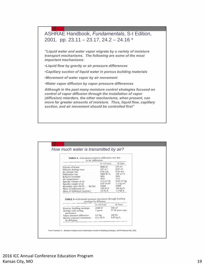
ASHRAE Handbook, Fundamentals, S-I Edition, 2001. pp. 23.11 – 23.17, 24.2 – 24.16 *
“Liquid water and water vapor migrate by a variety of moisture transport mechanisms. The following are some of the most important mechanisms:
•Liquid flow by gravity or air pressure differences
•Capillary suction of liquid water in porous building materials
•Movement of water vapor by air movement
•Water vapor diffusion by vapor pressure differences
Although in the past many moisture control strategies focused on control of vapor diffusion through the installation of vapor (diffusion) retarders, the other mechanisms, when present, can move far greater amounts of moisture. Thus, liquid flow, capillary suction, and air movement should be controlled first”
How much water is transmitted by air?
From Trechsel, H. , Moisture Analysis and Condensation Control in Building Envelopes. (ASTM Manual 40), 2001

2016 ICC Annual Conference Education ProgramKansas City, MO 20
Air Barrier / Vapor Barrier Interaction
0
2
4
6
8
10
0 2 4 6 8 10 12Pressure Difference (Pa)
Eq
uiv
alen
t P
erm
ean
ce .066 cfm/ft2 @ 75 Pa
.0098 cfm/ft2 @ 75 Pa
.02 cfm/ft2 @ 75 Pa
.03 cfm/ft2 @ 75 Pa
.053 cfm/ft2 @ 75 Pa
.15 cfm/ft2 @ 75 Pa
.20 cfm/ft2 @75 Pa
.27 cfm/ft2 @ 75 Pa
Data from TenWolde et. al., “Air Pressures in Wood Frame Walls”, Thermal Envelopes VII, 1998
At 4Pa (6mph) requires < 1/2 air leakage of E1677.
Air Barrier Rating
Vapor Permeability of Common Building Materials
.

2016 ICC Annual Conference Education ProgramKansas City, MO 21
Membranes the Function as Air Barriers
•Water Resistive Barriers (Housewraps, Building
Papers and Felts)
•Vapor Barrier (Self-Adhering membranes)
Vapor Barriers
•Polyethylene Film
•Kraft Paper
•Nylon Film

2016 ICC Annual Conference Education ProgramKansas City, MO 22

2016 ICC Annual Conference Education ProgramKansas City, MO 23
Hygrothermal Analysis
IBC 1405.3 Vapor retarders. Vapor retarders as described in Section 1405.3.3 shall be provided in accordance with Sections 1405.3.1 and 1405.3.2, or an approved design using accepted engineering practice for hydrothermal analysis.
ANSI/ASHRAE Standard 160-2009 Criteria for Moisture-Control Design Analysis in Buildings
E3054/E3054M-16 Standard Guide for Characterization and Use of Hygrothermal Models for Moisture Control Design in Building Envelopes
ANSI/ASHRAE Standard 160-2009 Criteria for Moisture-Control Design Analysis in Buildings
“1. PURPOSE
The purpose of this standard is to specify performance-based design criteria for predicting, mitigating or reducing moisture damage to the building envelope, materials, components, systems and furnishings, depending on climate, construction type, and HVAC system operation. These criteria include:
(a) criteria for selecting analytic procedures
(b) criteria for inputs, and
(c) criteria for evaluation and use of outputs.”

2016 ICC Annual Conference Education ProgramKansas City, MO 24
ANSI/ASHRAE Standard 160-2009 Criteria for Moisture-Control Design Analysis in Buildings
“2. SCOPE
2.1 This standard applies to the design of new buildings and to the retrofit and renovation of existing buildings.
2.2 This standard applies to all types of buildings, building components and materials.
2.3 This standard applies to all interior and exterior zones and building envelope cavities.
2.4 This standard does not directly apply to thermal comfort or acceptable indoor air quality.
2.5 This standard does not address the design of building components or envelopes to resist liquid water leakage from sources such as rainwater, ground water, flooding, or ice”
Start moisture design
Define building assembly
Assign material properties
Select initial conditions (4.1)
Select outdoor climate (4.5)
Select exposure conditions (4.6)
Determine indoor conditions (4.2-4.4, also flow chart 2)
Perform analysis (5)
Acceptable performance (6)?
Add initial drying procedure?
Change in con-struction design?
Report results (7)
Change in HVAC design.
yes
yes
no
no
no
yes
ANSI/ASHRAE Standard 160

2016 ICC Annual Conference Education ProgramKansas City, MO 25
Define Building Assembly
“Provide a description of the building envelope assembly.
• Assembly
• Type (wall, roof, etc.)
• Orientation
• Surface coefficients
• Air space locations and air space ventilation rates with outdoor air
• List of materials (include reference source of data)”
Start moisture design
Define building assembly
Assign material properties
Select initial conditions (4.1)
Select outdoor climate (4.5)
Select exposure conditions (4.6)
Determine indoor conditions (4.2-4.4, also flow chart 2)
Perform analysis (5)
Acceptable performance (6)?
Add initial drying procedure?
Change in con-struction design?
Report results (7)
Change in HVAC design.
yes
yes
no
no
no
yes
Assign Material Properties
“Provide data on each of the materials in the building envelope assembly.
• Material description
• Thickness
• Density
• Thermal conductivity, and its dependency on temperature and moisture content, if applicable Specific heat (heat capacity)
• Vapor permeance or permeability
• Sorption isotherm
• Liquid diffusivity or liquid conductivity
• Suction isotherm
• Initial moisture content
• Other material properties required for the analytic model, possibly including:
– Porosity
– Capillary saturation
– Maximum saturation
– Airflow permeability”
Start moisture design
Define building assembly
Assign material properties
Select initial conditions (4.1)
Select outdoor climate (4.5)
Select exposure conditions (4.6)
Determine indoor conditions (4.2-4.4, also flow chart 2)
Perform analysis (5)
Acceptable performance (6)?
Add initial drying procedure?
Change in con-struction design?
Report results (7)
Change in HVAC design.
yes
yes
no
no
no
yes

2016 ICC Annual Conference Education ProgramKansas City, MO 26
Select Initial Conditions
“4.1 Design Initial Moisture Content of Building Materials
The initial moisture content of construction materials in new construction to be used in calculations for this standard shall be two times EMC90 for concrete and two times EMC80 for all other materials, unless procedures to dry construction materials and/or procedures to protect construction materials and assemblies from wetting during construction are specified, in which case EMC90 for concrete and EMC80 for all other materials shall be used. In retrofit applications EMC90 for concrete and EMC80 for all other materials shall be used, unless measured moisture content values are available.”
Start moisture design
Define building assembly
Assign material properties
Select initial conditions (4.1)
Select outdoor climate (4.5)
Select exposure conditions (4.6)
Determine indoor conditions (4.2-4.4, also flow chart 2)
Perform analysis (5)
Acceptable performance (6)?
Add initial drying procedure?
Change in con-struction design?
Report results (7)
Change in HVAC design.
yes
yes
no
no
no
yes
Select outdoor Climate
“4.5 Moisture Design Weather Data
The analysis shall be performed using a minimum of 10 consecutive years of weather data or using the Moisture Design Reference Years weather data. The weather data shall include hourly data for:
• Dry bulb air temperature
• Vapor pressure, dew point temperature, wetbulb temperature, relative humidity, or humidity ratio
• Total solar insolation on a horizontal surface
• Average wind speed and direction
• Rainfall
• Cloud index”
Start moisture design
Define building assembly
Assign material properties
Select initial conditions (4.1)
Select outdoor climate (4.5)
Select exposure conditions (4.6)
Determine indoor conditions (4.2-4.4, also flow chart 2)
Perform analysis (5)
Acceptable performance (6)?
Add initial drying procedure?
Change in con-struction design?
Report results (7)
Change in HVAC design.
yes
yes
no
no
no
yes

2016 ICC Annual Conference Education ProgramKansas City, MO 27
Select exposure conditions
“4.6 Design Rain Loads on Walls
Design rain loads must be determined for walls exposed to rain. In the absence of a comprehensive wind-driven rain analysis, the amount of rain striking a vertical surface shall be calculated using the following equation:
rbv= FE●FD●FL●U●cos ●rh (4.6)
where• FE = rain exposure factor
• FD= rain deposition factor
• FL= empirical constant, 0.2 kgs/(m3mm) in SI, 0.46 lbh/(ft2miin.) in I-P
• U= hourly average wind speed at 10 m height, m/s (mi/h)
• = angle between wind direction and normal to the wall (Fig. 4.6.1)
• rh = rainfall intensity, horizontal surface, mm/h (in./h)
• rbv= rain deposition on vertical wall, kg/(m2h) (lb./(ft2h))”
Start moisture design
Define building assembly
Assign material properties
Select initial conditions (4.1)
Select outdoor climate (4.5)
Select exposure conditions (4.6)
Determine indoor conditions (4.2-4.4, also flow chart 2)
Perform analysis (5)
Acceptable performance (6)?
Add initial drying procedure?
Change in con-struction design?
Report results (7)
Change in HVAC design.
yes
yes
no
no
no
yes
Wind Direction
Select exposure conditions
“The exposure factor, FE, is influenced by the topography surrounding the building and height of the building. Recommended values are given in Table 4.6.1.
• Severe exposure includes hilltops, coastal areas, and funneled wind. Sheltered exposure includes shelter from trees, nearby buildings, or a valley.
The following deposition factors shall be used:• Walls below a steep-slope roof: FD = 0.35
• Walls below a low-slope roof: FD = 0.5
• Walls subject to rain runoff: FD =1.0 “
Start moisture design
Define building assembly
Assign material properties
Select initial conditions (4.1)
Select outdoor climate (4.5)
Select exposure conditions (4.6)
Determine indoor conditions (4.2-4.4, also flow chart 2)
Perform analysis (5)
Acceptable performance (6)?
Add initial drying procedure?
Change in con-struction design?
Report results (7)
Change in HVAC design.
yes
yes
no
no
no
yes
TABLE 4.6.1 Exposure factor. Terrain: Severe Medium Sheltered
Height (m) <10 1.3 1.0 0.7
10 – 15 1.3 1.1 0.8 15 - 20 1.4 1.2 0.9 20 - 30 1.5 1.3 1.1 30 - 40 1.5 1.4 1.2 40 - 50 1.5 1.5 1.3 > 50 1.5 1.5 1.5

2016 ICC Annual Conference Education ProgramKansas City, MO 28
Select exposure conditions
“4.6.1 Rain penetration.
In the absence of specific full scale test methods and data for the as-built exterior wall system being considered, the default value for water penetration through the exterior surface is 1% of the water reaching that exterior surface. The deposit site for the water shall be the exterior surface of the water-resistive barrier. If a water-resistive barrier is not provided then the deposit site shall be described and a technical rationale for its selection shall be provided.”
Start moisture design
Define building assembly
Assign material properties
Select initial conditions (4.1)
Select outdoor climate (4.5)
Select exposure conditions (4.6)
Determine indoor conditions (4.2-4.4, also flow chart 2)
Perform analysis (5)
Acceptable performance (6)?
Add initial drying procedure?
Change in con-struction design?
Report results (7)
Change in HVAC design.
yes
yes
no
no
no
yes
Select exposure conditions
“4.4 Design Air Pressure Differentials and Flows.
Analysis of the effect of air pressure differentials and air flows is optional. If the effect is not considered in the design analysis, this shall be expressly stated in the report. If the effect is included, Section 4.4.1 shall apply.
4.4.1 Effect of Air Pressure Differentials Included in Design Analysis. If the air pressure differential between indoors and outdoors is controlled, that air pressure differential shall be used in the design analysis.
If the air pressure differential is not managed, one of two alternative procedures shall be followed.
• Design Air Pressure Differential, Alternative 1: The design air pressure differential shall be calculated from design ventilation rates, including the planned fresh air supply and exhaust rates, the building air tightness, wind pressures, using Moisture Design Weather Data (section 4.5), and stack pressure (section 4.4.1.3).
• Design Air Pressure Differential, Alternative 2: A design air pressure differential of +5 Pa (0.02 in. w.c.) above outdoor air pressure (air flow to the exterior) shall be used when the 24-hour running average outdoor temperature is below the indoor design temperature, and –5 Pa (air flow to the interior) when the 24-hour running average outdoor temperature is above the indoor design temperature..
Stack pressure differential at the top of the wall of the top floor shall be calculated (section 4.4.1.3) for buildings taller than three stories and used as the design air pressure differential if greater than 5 Pa (0.02 in. w.c.), unless the building design includes effective measures to pressure-isolate each floor.”
Start moisture design
Define building assembly
Assign material properties
Select initial conditions (4.1)
Select outdoor climate (4.5)
Select exposure conditions (4.6)
Determine indoor conditions (4.2-4.4, also flow chart 2)
Perform analysis (5)
Acceptable performance (6)?
Add initial drying procedure?
Change in con-struction design?
Report results (7)
Change in HVAC design.
yes
yes
no
no
no
yes

2016 ICC Annual Conference Education ProgramKansas City, MO 29
Select exposure conditions
“4.4.1.3 Stack Pressure differential.: The stack pressure at the top of the wall of the top floor shall be estimated using the following equation:
∆Ps=C((Ti-To)/Ti) gH/2 (4.5)
where, in I-P units: • ∆Ps = design stack pressure (in. of water)
• C = conversion factor (equals 0.00598 (in. of water ·ft·s2/lb)[F2]
• = density of outdoor air (0.075 lb/ft3)
• To = outdoor temperature (R)
• Ti = indoor temperature (R)
• g = gravitational constant (32.2 ft/s2), and
• H = height of the building (ft).
If the airtightness of the envelope is known, it shall be used to calculate the air flow rate through the envelope at the design pressure. If the airtightness is not known, an airtightness of 0.0008 in.2/ft2 (0.055 cm2/m2) shall be used in an airtight building and 0.0042 in.2/ft2 (0.29 cm2/m2) for standard construction. With a design pressure of 5 Pa, this translates into an air leakage rate of 0.0031 cfm/ft2 (0.016 L/(s·m2)) in an airtight building and 0.016 cfm/ft2 (0.084 L/(s·m2)) for standard construction. A description of the air flow pathways and a rationale for that selection shall be reported.”
Start moisture design
Define building assembly
Assign material properties
Select initial conditions (4.1)
Select outdoor climate (4.5)
Select exposure conditions (4.6)
Determine indoor conditions (4.2-4.4, also flow chart 2)
Perform analysis (5)
Acceptable performance (6)?
Add initial drying procedure?
Change in con-struction design?
Report results (7)
Change in HVAC design.
yes
yes
no
no
no
yes
Determine indoor conditions: Temperature
“4.2 Indoor Design Temperature
If the design or operating specifications for the building specify indoor operating temperatures, or the indoor design temperatures are specified by applicable code, regulation, or law, these temperatures shall be used. Otherwise, the indoor temperatures specified in Table 4.2 shall be used. “
Start moisture design
Define building assembly
Assign material properties
Select initial conditions (4.1)
Select outdoor climate (4.5)
Select exposure conditions (4.6)
Determine indoor conditions (4.2-4.4, also flow chart 2)
Perform analysis (5)
Acceptable performance (6)?
Add initial drying procedure?
Change in con-struction design?
Report results (7)
Change in HVAC design.
yes
yes
no
no
no
yes
TABLE 4.2 Indoor Design Temperature Indoor Design Temperature, °C (°F) 24-hour running average of
outdoor temperature Heating only Heating and air-conditioning To, 24h ≤ 18.3°C (To, 24h ≤ 65°F)
21.1°C (70°F)
21.1 °C (70°F)
18.3°C < To, 24h ≤ 21.1°C (65°F < To, 24h ≤ 70°F)
To, 24h + 2.8°C (To, 24h+5°F)
To, 24h + 2.8°C (To, 24h+5°F)
To, 24h>21.1°C (70°F) (To, 24h>70°F)
To, 24h + 2.8°C (To, 24h+5°F)
23.9°C (75°F)
Note: To, 24h = 24-hour average outdoor temperature

2016 ICC Annual Conference Education ProgramKansas City, MO 30
Determine indoor conditions: Humidity
“4.3 Indoor Design Humidity
If the HVAC equipment and controls are included in the design, the intended design indoor humidity shall be used. If no such provisions are made, then indoor design humidity shall be determined by one of three methods:
• (a) Simplified Method (In accordance with section 4.3.1),
• (b) Intermediate Method (In accordance with section 4.3.2), or
• (c) Full Parameter Calculation (In accordance with section 4.3.3).”
Start moisture design
Define building assembly
Assign material properties
Select initial conditions (4.1)
Select outdoor climate (4.5)
Select exposure conditions (4.6)
Determine indoor conditions (4.2-4.4, also flow chart 2)
Perform analysis (5)
Acceptable performance (6)?
Add initial drying procedure?
Change in con-struction design?
Report results (7)
Change in HVAC design.
yes
yes
no
no
no
yes
Section 4.2
Use specified design humidity
Use default values Indoor humidity known?
yes no
Section 4.4
Use Flowchart 3
Simplified method (4.3.1)
Intermediate method (4.3.2)
Full parameter method (4.3.3)

2016 ICC Annual Conference Education ProgramKansas City, MO 31
Determine indoor conditions: Humidity
“4.3.1 Indoor Design Humidity, Simplified Method.
Design indoor humidity according to the simplified method is a function of average daily outdoor temperature and is given in Table 4.3.1 (Figure 4.3.1):”
Start moisture design
Define building assembly
Assign material properties
Select initial conditions (4.1)
Select outdoor climate (4.5)
Select exposure conditions (4.6)
Determine indoor conditions (4.2-4.4, also flow chart 2)
Perform analysis (5)
Acceptable performance (6)?
Add initial drying procedure?
Change in con-struction design?
Report results (7)
Change in HVAC design.
yes
yes
no
no
no
yes
Table 4.3.1 Design indoor RH, Simplified Method Daily Average
Outdoor Temperature, °C
Design RH, % (Based on °C)
Daily Average Outdoor Temperature, °F
Design RH, % (Based on °F)
Below -10°C 40% Below 14°F 40% -10°C≤ To, daily≤20°C 40% + (To, daily+10) 14°F≤ To, daily≤68°F 40% + (To, daily-14)/1.8 Above 20°C 70% Above 68°F 70%
-20 -10 0 10 20 30 20
30
40
50
60
70
80
Ind
oo
r D
esi
gn
RH
[%
]
Daily Average Outdoor Temperature [°C]
68 Daily Average Outdoor Temperature [°F]
14
4.3.2 Indoor Design Humidity, Intermediate Method. In this method, indoor design humidity is determined from hourly weather and the type of HVAC equipment.
Start moisture design
Define building assembly
Assign material properties
Select initial conditions (4.1)
Select outdoor climate (4.5)
Select exposure conditions (4.6)
Determine indoor conditions (4.2-4.4, also flow chart 2)
Perform analysis (5)
Acceptable performance (6)?
Add initial drying procedure?
Change in con-struction design?
Report results (7)
Change in HVAC design.
yes
yes
no
no
no
yes
Intermediate method (4.3.2)
Air-conditioner
on?
Determine moisture generation (4.3.2.1.1 or 2)
Determine ventilation rate (4.3.2.1.3 or 4)
Calculate humidity(Eq. 4.1)
Section 4.4
Calculate humidity(Eq. 4.4)
Humidistat control or
dehumidifier?
yes no
yes no
RH control setpoint
specified?
Setpoint = 50% RH
RH from Eq 4.4 > setpoint?
Use RH setpoint
yes no Use calculated humidity (Eq. 4.4)
yes no
De-humidifier?
RH control setpoint
specified?
Setpoint = 50% RH
RH from Eq 4.1 > setpoint?
Use calculated humidity (Eq. 4.1)
Use RH setpoint
yes no
noyes
yes no

2016 ICC Annual Conference Education ProgramKansas City, MO 32
Determine indoor conditions: Humidity
“4.3.3 Indoor Design Humidity, Full Parametric Calculation.
Full parametric evaluation of indoor humidity requires comprehensive inputs to support analysis of the hygrothermal response and dynamic hygrothermal flux contribution of building elements, finishes and furniture (hygric buffering). The analysis shall include thermal and mass balances and shall use simulation algorithms and time-step intervals that capture hygrothermal response of sensitive materials and conditions.
Required inputs include: • hygrothermal properties of building materials, finishes and furniture,
• design initial moisture conditions (In accordance with Section 4.1)
• design indoor temperatures (In accordance with Section 4.2),
• design ventilation rates (In accordance with Section 4.3.2.1.3 or 4.3.2.1.4),
• design moisture generation rates (In accordance with Section 4.3.2.1.1 or 4.3.2.1.2),
• effect of active dehumidification systems,
• design pressure data (In accordance with Section 4.4.1),
• design weather data (In accordance with Section 4.5),
• design rain loads (In accordance with Section 4.6).”
Start moisture design
Define building assembly
Assign material properties
Select initial conditions (4.1)
Select outdoor climate (4.5)
Select exposure conditions (4.6)
Determine indoor conditions (4.2-4.4, also flow chart 2)
Perform analysis (5)
Acceptable performance (6)?
Add initial drying procedure?
Change in con-struction design?
Report results (7)
Change in HVAC design.
yes
yes
no
no
no
yes
Perform Analysis
“CRITERIA FOR SELECTING ANALYTICAL PROCEDURES
This section sets minimum acceptable criteria for analytical tools capable of analyzing thermal and moisture transfer and conditions in building envelope components. The analytic procedure shall be transient with a maximum time step of one hour. As a minimum requirement, the procedure shall have the ability to include:
• Energy transport, including temperature effects of phase change
• Material properties as a function of moisture content
• Water (liquid and vapor) transport, including:– Capillary transport
– Moisture deposition on surfaces
– Storage in materials
– Vapor diffusion
– Water leakage.
• If the design includes a ventilated cavity, the analysis shall include the effects of the cavity.
• The analytic procedure shall provide the following output:– Temperature and surface relative humidity at each surface and at the interface of the material layers,
– Average temperature for each material layer,
– Average moisture content for each material layer.”
Start moisture design
Define building assembly
Assign material properties
Select initial conditions (4.1)
Select outdoor climate (4.5)
Select exposure conditions (4.6)
Determine indoor conditions (4.2-4.4, also flow chart 2)
Perform analysis (5)
Acceptable performance (6)?
Add initial drying procedure?
Change in con-struction design?
Report results (7)
Change in HVAC design.
yes
yes
no
no
no
yes

2016 ICC Annual Conference Education ProgramKansas City, MO 33
MOISTURE PERFORMANCE EVALUATION CRITERIA
“This section sets performance criteria that shall be met to minimize the undesirable effects of moisture in a building or building envelope. These criteria apply to all materials and surfaces, except the exterior surface of the building envelope.
6.1 Conditions Necessary to Minimize Mold Growth
In order to prevent problems associated with mold growth on the surfaces of components of building envelope assemblies, all of the following conditions shall be met:
• 30-day running average surface RH < 80% when the 30-day running average surface temperature is between 5C (41F) and 40C (104F), and,
• 7-day running average surface RH < 98% when the 7-day running average surface temperature is between 5C (41F) and 40C (104F), and,
• 24-h running average surface RH < 100% when the 24-h running average surface temperature is between 5C (41F) and 40C (104F).
• Materials which are naturally resistant to mold or have been chemically treated to resist mold growth may be able to resist higher surface relative humidities and/or to resist for longer periods as specified by the manufacturer. The criteria used in the evaluation shall be stated in the report.
6.2 Corrosion
Requirements for prevention of corrosion shall be derived from the properties and function of the particular metals used in construction. If no such information is available, the 30-day running average of hourly values of surface RH of the metal shall remain less than 80%. “
Protection against condensation
Vapor retarders to reduce water vapor entry, but must be balanced with drying of building assemblies.
Can be defeated by air leakage.
Dependent on Exterior &
Interior Conditions

2016 ICC Annual Conference Education ProgramKansas City, MO 34
Summary
The IBC and IRC both contain requirements for where vapor retarders are required on the interior of frame walls.
driven by condensation of interior moisture
The IBC also contains requirements for where vapor retarders are not to be used.
driven by drying and prevention of inward drive
Hygrothermal Analysis is a growing area and is now specifically allowed as a compliance method.
Thank you for your attention. Please ask any questions.

2016 ICC Annual Conference Education ProgramKansas City, MO 35
Copyright© 2016 E. I. du Pont de Nemours and Company. The DuPont Oval, DuPont™ and The miracles of science™ are trademarks of E. I. du Pont de Nemours and Company or its affiliates. All rights reserved.