IC-QA-R82 Lean-Mix Concrete Subbase
94
Edition 4/ Revision 4 TRANSPORT FOR NSW February 2021 TRANSPORT FOR NSW (TfNSW) QA SPECIFICATION R82 LEAN-MIX CONCRETE SUBBASE NOTICE This document is a Transport for NSW QA Specification. It has been developed for use with roadworks and bridgeworks contracts let by Transport for NSW or by local councils in NSW. It is not suitable for any other purpose and must not be used for any other purpose or in any other context. Copyright in this document belongs to Transport for NSW. REVISION REGISTER Ed/Rev Number Clause Number Description of Revision Authorised By Date Ed 3/Rev 0 Completely revised in line with RTA R83 and RTA R84. Some requirements transferred to Annexure R82/3. GM, RNIC (W Ho) 30.01.98 Ed 3/Rev 1 Contents Table & 5.3 Duplicate clause heading deleted. GM, RNIC 15.04.98 Various Minor editorial changes. 2.2 Table R82.2 Reference to alkali reactivity deleted. Annex 3 Sub-clause numbers changed for A2.1, A2.6, A3.2, A4.1, A5.4.2. A1.2 Incorporated into Clause 1.2. A5.3 Paragraphs rearranged. Ed 3/Rev 2 1.2, Annex 1 - 4.3.8.4 Reference to RTA T367 deleted. GM, RNIC 23.12.98 2.2(b), 2.3, 3.8.1(i)(G) Deleted requirement for alkali-aggregate reactivity testing (& Annex R82/1 - Clause 2.1) 4.3.7 (e) Rate specified now a minimum. Ed 3/Rev 3 1.2, 2.8 AS 1650 replaced by AS/NZS 4680. GM, RNIC 05.08.99 2.9 Reference to AS 1379 changed. 4.3.7 Emulsion curing rate increased. 4.10.2 (c) Sprayed bituminous seal added. 5.4.3 Thickness assessment changed. 5.4.4 Offsets with extra base. Annex R82/6 New annexure listing Identified Records.
Transcript of IC-QA-R82 Lean-Mix Concrete Subbase

Edition 4/ Revision 4 TRANSPORT FOR NSW February 2021
TRANSPORT FOR NSW (TfNSW)
QA SPECIFICATION R82
LEAN-MIX CONCRETE SUBBASE
NOTICE
This document is a Transport for NSW QA Specification. It has been developed for use with roadworks and bridgeworks contracts let by Transport for NSW or by local councils in NSW. It is not suitable for any other purpose and must not be used for any other purpose or in any other context.
Copyright in this document belongs to Transport for NSW.
REVISION REGISTER
Ed/Rev Number
Clause Number Description of Revision Authorised
By Date
Ed 3/Rev 0 Completely revised in line with RTA R83 and RTA R84. Some requirements transferred to Annexure R82/3.
GM, RNIC (W Ho)
30.01.98
Ed 3/Rev 1 Contents Table & 5.3
Duplicate clause heading deleted. GM, RNIC 15.04.98
Various Minor editorial changes.
2.2 Table R82.2
Reference to alkali reactivity deleted.
Annex 3 Sub-clause numbers changed for A2.1, A2.6, A3.2, A4.1, A5.4.2.
A1.2 Incorporated into Clause 1.2.
A5.3 Paragraphs rearranged.
Ed 3/Rev 2 1.2, Annex 1 - 4.3.8.4
Reference to RTA T367 deleted. GM, RNIC 23.12.98
2.2(b), 2.3, 3.8.1(i)(G)
Deleted requirement for alkali-aggregate reactivity testing (& Annex R82/1 - Clause 2.1)
4.3.7 (e) Rate specified now a minimum.
Ed 3/Rev 3 1.2, 2.8 AS 1650 replaced by AS/NZS 4680. GM, RNIC 05.08.99
2.9 Reference to AS 1379 changed.
4.3.7 Emulsion curing rate increased.
4.10.2 (c) Sprayed bituminous seal added.
5.4.3 Thickness assessment changed.
5.4.4 Offsets with extra base.
Annex R82/6 New annexure listing Identified Records.

ii
Ed/Rev Number
Clause Number Description of Revision Authorised
By Date
Ed 3/Rev 4 1.2, 3.8, 4.4, 4.9, 5.3.3.4,
Annexure R82/4 – A4.2.2 Minor changes.
GM, RNIC 31.08.00
2.2 Material finer than 75 µm limit and organic impurities requirement changed.
2.5 Alkali contribution for fly ash mixes changed.
2.10 Concrete strength grade for subgrade beams changed.
3.6 Slump range changed.
3.7 Bleeding requirements deleted.
4.2.2 Forming time recording changed.
4.3.4 Concrete temp. range changed.
4.5.4 Joint offset limits changed.
Annex R82/1 Particle size distribution testing requirements changed.
A4.2.2 Continuous mixers added.
Ed 3/Rev 5 1.2, 2.8 AS 1302, AS 1303 and AS 1304 replaced by AS/NZS 4671.
GM, RNIC 21.08.03
1.2, 2.4 Detailed cement requirements replaced by RTA 3211. Cement sample required. AS 2349 added.
1.2 Various revisions to Table R82.1.
4.2.2 Mixing time, batch delivery docket and consistence details revised.
4.3.1 Supplementary manual vibration must be used.
4.3.2 Establish and document vibrator operating parameters.
4.3.8.2 Nonconformity associated with concrete exposed to rain.
4.5 Management of detritus from sawcutting added.
4.5.4, 5.4.4 Minor editorial changes.
4.10.1 Timing for completion of de/bonding treatment.
4.10.2 Item (d) SFCP added. De/bonding compounds added to items (e) and (f).
4.10.5 Binder details revised.
5.1.1 Description of cracking revised.
5.1.2 Corrective action required.

iii
Ed/Rev Number
Clause Number Description of Revision Authorised
By Date
Ed 3/Rev 5 5.1.3 Minor editorial changes.
(cont’d) 5.3.3.3 General revision.
5.3.3.4 General revision.
5.6.1 Management of detritus from sawcutting added.
5.6.2 General revision.
5.6.3 General revision.
5.4.4 Assessing thicknesses below 5 mm deleted.
A5.3.3, A5.3.4
Correction for core age deleted.
Annexure R82/4
The following definitions revised: - Completion of batching; - Retempering; - Skew, - Road; - Test result; - Test value
Ed 3/Rev 6 2.4 RTA Laboratory details updated. GM, IC 23.03.07
4.4 Requirement for Concrete Paving Crew Training records added to Hold Point.
Annex R82/3, A4.3.3
Training requirements amended to include reference to Concrete Paving Crew Training.
Ed 3/Rev 7 2.8 Steel reinforcement requirements clarified. GM, IC 14.10.10
Annex R82/1 ‘Frequency of Testing’ moved from Annex 1 to Annexure 5 (to be consistent with R83 & R84); Annexures following renumbered.
Annex R82/7 Certification requirement for steel reinforcement added.
Ed 4/Rev 0 Global Content totally reorganised and rewritten to improve clarity and remove duplication.
Content of previous Annex 3 moved to main body of spec.
Previous Annex 4 and 5 moved to Annex L and Clause 1.3 respectively. Previous Annex 6 and 7 moved to Annex C. Previous clauses 1.2 and 6 moved to Annex M and B respectively.
DCS 04.04.18
“Lot” changed to “sub-Lot”, to be consistent with definition of “Lot” in Q.
1.1 Reference to AS 2706 for interpretation of limiting values deleted.

iv
Ed/Rev Number
Clause Number Description of Revision Authorised
By Date
Ed 4/Rev 0 (cont’d)
1.3 Definitions, Acronyms and Symbols revised and updated.
2.1.1 Unacceptable types of steel slag aggregates clarified.
2.1.2 AS reference for aggregate sampling added.
2.1.3 New clause on stockpiles.
2.2 Table 1 - fine aggregate property requirements expanded and updated. Notes to Table amended.
Figure 1 - flowchart on fine aggregate acceptance added.
2.3 Table 2 - coarse aggregate property requirements expanded and updated. Notes to Table amended.
2.4 New clause on alkali-aggregate reactivity added.
2.5 New clause on combined aggregate particle size distribution testing.
2.6 Requirements for cementitious materials simplified to only comply with spec 3211.
2.7 Requirement added for case when water is drawn from source which is other than drinking water supply.
2.8.1 Mention of specific types of admixtures removed.
2.8.3 New sub-clause on use of air entraining agent.
2.9.1 Curing compounds requirements revised and updated.
2.9.2 Test results demonstrating conformity of curing compound specified to be not older than 3 years.
3.2 Cementitious content requirement removed and cross referenced to spec 3211.
3.3 Previous clause on combine aggregate particle size distribution considered to be superfluous and deleted.
Table 4 – maximum 28 day cylinder compressive strength increased from 15 MPa to 17 MPa. Note added to Table.
v
Ed/Rev Number
Clause Number Description of Revision Authorised
By Date
Ed 4/Rev 0 (cont’d)
3.4 Slump ranges for slipform paving and fixed-form paving broadened to provide greater flexibility for different paver characteristics.
Slump range for paving in transition zones added.
3.4 Requirement for slump to be within ±5 mm from slump value of laboratory tests on nominated mix added.
3.5 Requirements on drying shrinkage at 21 days in previous Table 8 moved to 2 new tables, each under separate sub-clauses.
Dry shrinkage at 56 days added to tables. Conformity clarified to be satisfaction of either one of the drying shrinkage requirements.
3.6.1 Table 7 – upper limits for chloride ion content and sulfate ion content added. Notes to Table added.
3.7 Age of test results for nominated mix increased from 12 months to 18 months.
Conditional reduction of scope or waiving of laboratory trial mix added.
3.8.1 Option to use a mix from RMS Register of Concrete Mixes added.
4.3.1 New sub-clause on measurement of mixing time, expanding on previous description under Annex 5.1 “Definitions”.
4.3.2 Clarification added that up to 10% of remaining design total water content may be added after the defined mixing time, subject to increase in mixing time.
4.3.4 New Hold Point on submission of mixer uniformity test results added.
4.3.5.2 New sub-clause on addition of admixture into mobile mixer after completion of batching.
4.4.2 New sub-clause on addition of constituent materials after completion of batching.
6.2.2 Air temperature limits for placing concrete amended.
6.6.1 Slab dimensional limits added.
6.9.4 Curing compound types applicable for different overlying base types revised and updated.

vi
Ed/Rev Number
Clause Number Description of Revision Authorised
By Date
Ed 4/Rev 0 (cont’d)
6.9.5 Figure 3 on curing compound spraying overlap added.
6.10.2 New sub-clause on assessment and reporting of paving trial.
6.10.2 Previous Hold Point on commencement of trial paving section replaced by new Hold Point on commencement of paving for rest of LCS after trial paving.
6.11.1 Requirement added to obtain prior agreement of Principal if claim for payment to be made under Pay Item P5 for use of protective subbase covers.
6.11.3 Types of operations permitted to traffic LCS after achievement of 4 MPa compressive strength extended.
6.12.1 Circumstances for debonding/bonding treatment clarified.
New Hold Point on commencement of surface debonding/bonding treatment added.
6.12.2 Table 13 - Debonding/bonding treatments for different overlying base types updated.
Notes to table added.
6.12.5.1 C240 included for use as cutback bitumen seal.
Maximum cutter oil for cut back reduced from 3% to 2%.
Minimum aggregate size of BS increased from 5 mm to 7 mm.
6.12.5.2 Minimum aggregate size of BES increased from 5 mm to 7 mm.
Aggregate spreading rate specified.
7.1.3 Figure 4 redrawn covering more cases, to improve clarity.
8.1 Previous Clause 5.1 on types of concrete cracking rewritten.
8.2 New clause added on crack assessment including new Witness Point and Hold Point, and new Figures 4 and 5 with flowcharts on dealing with non-typical drying and plastic shrinkage cracks.
8.3.5 Age correction factor removed.
8.4.7 Table 15 – deductions for LCS thickness deficiency distinguished between overlying base type for concrete and asphalt.

vii
Ed/Rev Number
Clause Number Description of Revision Authorised
By Date
Ed 4/Rev 0 (cont’d)
8.4.8 Table 16 – previously Table 11. Table rearranged to harmonise with Table 15.
8.8.3 Minimum dimensions of nonconforming LCS for removal revised.
Annex A Annexure added for inclusion of project specific requirements.
Annex B Pay item P5 – new pay item for provision of covers for temperature protection.
Pay item P6 – previously pay item P5.
Annex D New annexure on planning documents.
Annex E Test method for mixer uniformity with respect to mass per unit volume and compressive strength added.
Annex H Paving trial report contents added.
Ed 4/Rev 1 Global References to “Roads and Maritime Services” or “RMS” changed to “Transport for NSW” or “TfNSW” respectively.
DCS 22.06.20
Ed 4/Rev 2 Global Minor editorial changes to improve clarity. MCQ 26.10.20
1.3 Definitions and acronyms updated.
3.8.4 Requirement that test specimens from nominated mix be taken from same batch added.
4.3.2 Measurement of minimum mixing time clarified.
4.3.6 Previously clause 4.3.4 retitled “Hold Point”.
4.6 Previously clause 4.5.5. Subsequent clauses renumbered.
Exception to re-mixing requirements deleted.
6.3.1 Statement on unsupported longitudinal edge moved here from previous clause 6.3.5.
8.8.1 New clause on boundaries of section for removal and incorporating part of previous clauses 8.8.2 and 8.8.3.
Minimum dimensions of replacement slab and residual slab tabulated in Table 17.
8.8.2 Clause combining previous clauses 8.8.1 and 8.8.2, retitled “Sawcutting”.
8.8.3 New clause on “Replacement”.
Annex C Schedule of Hold Points and Witness Points updated.
Clause references in Schedule of Identified Records updated

viii
Ed/Rev Number
Clause Number Description of Revision Authorised
By Date
Ed 4/Rev 2 Annex D Clause references updated.
(cont’d) Annex L Clause references updated.
Ed 4/Rev 3 2.8.1 Reference to AS 1478.2 deleted. MCQ 05.11.20
Annex M Referenced documents updated.
Ed 4/Rev 4 2.2 Maximum size of fine aggregate no longer specified.
Table 1 – Note (8) added.
SMCSp 17.02.21
2.3 Table 2 - Note (4) added.
6.1.3 Previous sub-clause on Concrete Paving Crew Training deleted (replaced by Clause 6.2). Subsequent sub-clause renumbered.
6.2 New clause on concreting personnel requirements, including Grey Card Training. Hold Point added. Subsequent clauses renumbered.
Annex C1 Schedule of Hold Points and Witness Points updated.
Annex C2 Schedule of Identified Records updated.
Annex D Planning Documents updated.
Annex M Referenced documents updated.

ix
GUIDE NOTES (Not Part of Contract Document)
Specification R82 is intended for use in construction of road pavements for highways which carry substantial volumes of heavy road vehicles. It is unlikely to be suitable for use in construction of other types of pavements such as industrial, commercial or residential pavements without modification.
Edition 4
Edition 4 has been totally reorganised and rewritten to improve clarity and remove duplication, and incorporate a number of changes to technical requirements.
The front Revision Register provides a summary of the main changes in Edition 4. Due to the reorganisation and the rewording of the content, in many cases different parts of a clause in Edition 3 have been moved to different locations in Edition 4. Such clauses too may be reworded without changing the intent. Such changes are not specifically listed in the Revision Register.


Edition 4 / Revision 4 TRANSPORT FOR NSW February 2021
QA SPECIFICATION R82
LEAN-MIX CONCRETE SUBBASE Copyright – Transport for NSW
IC-QA-R82
VERSION FOR: DATE:


Lean-mix Concrete Subbase R82
Ed 4 / Rev 4 i
CONTENTS
CLAUSE PAGE
FOREWORD ........................................................................................................................................ III TfNSW Copyright and Use of this Document.......................................................................... iii Revisions to Previous Version ................................................................................................. iii Project Specific Changes ........................................................................................................ iii
1 GENERAL .................................................................................................................................. 1 1.1 Scope ......................................................................................................................... 1 1.2 Structure of the Specification ..................................................................................... 1 1.3 Definitions, Acronyms and Symbols ........................................................................... 2
2 MATERIALS ............................................................................................................................... 6 2.1 Aggregates – General ................................................................................................. 6 2.2 Fine Aggregate........................................................................................................... 7 2.3 Coarse Aggregate ....................................................................................................... 9 2.4 Alkali-aggregate Reactivity ..................................................................................... 10 2.5 Combined Aggregate Particle Size Distribution ....................................................... 11 2.6 Cementitious Materials ............................................................................................ 11 2.7 Water ....................................................................................................................... 11 2.8 Admixtures .............................................................................................................. 11 2.9 Curing Compounds................................................................................................... 12 2.10 Steel Reinforcement (for Subgrade Beam) ............................................................... 13
3 DESIGN OF CONCRETE MIXES .................................................................................................. 13 3.1 General .................................................................................................................... 13 3.2 Cementitious Content ............................................................................................... 13 3.3 Compressive Strength ............................................................................................... 14 3.4 Consistence .............................................................................................................. 14 3.5 Shrinkage ................................................................................................................. 14 3.6 Other Concrete Attributes ........................................................................................ 16 3.7 Trial Mixing for Mix Design .................................................................................... 17 3.8 Submission of Nominated Mixes .............................................................................. 17 3.9 Variation to Authorised Nominated Mix .................................................................. 19
4 PRODUCTION AND TRANSPORT OF CONCRETE.......................................................................... 19 4.1 General .................................................................................................................... 19 4.2 Production Mixes ..................................................................................................... 20 4.3 Mixing of Concrete .................................................................................................. 21 4.4 Transport of Concrete............................................................................................... 23 4.5 Consistence (Slump) of Concrete ............................................................................. 23 4.6 Retempering............................................................................................................. 25 4.7 Forming Time .......................................................................................................... 25 4.8 Air Content of Concrete ........................................................................................... 26
5 SUBGRADE BEAM .................................................................................................................... 27 5.1 General .................................................................................................................... 27 5.2 Steel Reinforcement ................................................................................................. 27 5.3 Concrete .................................................................................................................. 28 5.4 Curing and Protection from Damage ........................................................................ 29
6 SUBBASE CONCRETE PAVING .................................................................................................. 29

R82 Lean-mix Concrete Subbase
ii Ed 4 / Rev 4
6.1 General .................................................................................................................... 29 6.2 Concreting Personnel ............................................................................................... 30 6.3 Temperature and Weather Condition ....................................................................... 31 6.4 Slipform (Mechanical) Paving ................................................................................. 31 6.5 Fixed-form (Manual) Paving .................................................................................... 33 6.6 Paving in Transition Zones ...................................................................................... 34 6.7 Joints and Edges ...................................................................................................... 34 6.8 Prevention of Moisture Loss .................................................................................... 36 6.9 Surface Finish .......................................................................................................... 38 6.10 Curing...................................................................................................................... 38 6.11 Concrete Paving Trial .............................................................................................. 41 6.12 Protection of Work .................................................................................................. 43 6.13 Surface Debonding/Bonding Treatment ................................................................... 44
7 SURVEY .................................................................................................................................. 46 7.1 Levels ...................................................................................................................... 47 7.2 Alignment ................................................................................................................ 49 7.3 Surface Profile ......................................................................................................... 49
8 CONFORMITY .......................................................................................................................... 49 8.1 Types of Concrete Cracking..................................................................................... 49 8.2 Crack Assessment .................................................................................................... 50 8.3 Concrete Compressive Strength ............................................................................... 53 8.4 Thickness ................................................................................................................. 56 8.5 Alignment, Levels and Surface Profile..................................................................... 58 8.6 Redesign of Pavement Levels .................................................................................. 58 8.7 Restoration of LCS After Coring ............................................................................. 59 8.8 Removal and Replacement of Lean-mix Concrete Subbase ...................................... 59
ANNEXURE R82/A – PROJECT SPECIFIC REQUIREMENTS.................................................................... 61
ANNEXURE R82/B – MEASUREMENT AND PAYMENT ......................................................................... 62
ANNEXURE R82/C – SCHEDULES OF HOLD POINTS, WITNESS POINTS AND IDENTIFIED RECORDS ....... 64 C1 Schedule of Hold Points and Witness Points ............................................................ 64 C2 Schedule of Identified Records ................................................................................ 64
ANNEXURE R82/D – PLANNING DOCUMENTS .................................................................................... 66
ANNEXURE R82/E – MIXER UNIFORMITY TESTING ............................................................................ 68 E1 General .................................................................................................................... 68 E2 Stationary Mixers .................................................................................................... 68 E3 Mobile Mixers ......................................................................................................... 70
ANNEXURES R82/F TO R82/G – (NOT USED) ..................................................................................... 71
ANNEXURE R82/H – PAVING TRIAL REPORT ..................................................................................... 72
ANNEXURES R82/I TO R82/K – (NOT USED) ...................................................................................... 72
ANNEXURE R82/L – MINIMUM FREQUENCY OF TESTING ................................................................... 73
ANNEXURE R82/M – REFERENCED DOCUMENTS ............................................................................... 76
LAST PAGE OF THIS DOCUMENT IS ...................................................................................................... 78

Lean-mix Concrete Subbase R82
Ed 4 / Rev 4 iii
FOREWORD
TFNSW COPYRIGHT AND USE OF THIS DOCUMENT
Copyright in this document belongs to Transport for NSW.
When this document forms part of a contract
This document should be read with all the documents forming the Contract.
When this document does not form part of a contract
This copy is not a controlled document. Observe the Notice that appears on the first page of the copy controlled by TfNSW. A full copy of the latest version of the document is available on the TfNSW Internet website: http://www.rms.nsw.gov.au/business-industry/partners-suppliers/specifications/index.html
REVISIONS TO PREVIOUS VERSION
This document has been revised from Specification TfNSW R82 Edition 4 Revision 3.
All revisions to the previous version (other than minor editorial and project specific changes) are indicated by a vertical line in the margin as shown here, except when it is a new edition and the text has been extensively rewritten.
PROJECT SPECIFIC CHANGES
Any project specific changes are indicated in the following manner:
(a) Text which is additional to the base document and which is included in the Specification is shown in bold italics e.g. Additional Text.
(b) Text which has been deleted from the base document and which is not included in the Specification is shown struck out e.g. Deleted Text.

(TfNSW COPYRIGHT AND USE OF THIS DOCUMENT - Refer to the Foreword after the Table of Contents)
Ed 4 / Rev 4 1
TfNSW QA SPECIFICATION R82
LEAN-MIX CONCRETE SUBBASE
1 GENERAL
1.1 SCOPE
This Specification sets out the requirements for the construction of lean-mix concrete subbase (LCS). It includes the requirements for:
• constituent materials;
• concrete mix design;
• production and transport of concrete;
• concrete subbase paving;
• survey;
• sampling and testing;
• conformity criteria.
1.2 STRUCTURE OF THE SPECIFICATION
This Specification includes a series of annexures that detail additional requirements.
1.2.1 Project Specific Requirements
Project specific details of work are shown in Annexure R82/A.
1.2.2 Measurement and Payment
The method of measurement and payment is detailed in Annexure R82/B.
1.2.3 Schedules of HOLD POINTS, WITNESS POINTS and Identified Records
The schedules in Annexure R82/C list the HOLD POINTS and WITNESS POINTS that must be observed. Refer to Specification TfNSW Q for the definitions of HOLD POINTS and WITNESS POINTS.
The records listed in Annexure R82/C are Identified Records for the purposes of TfNSW Q Annexure Q/E.
1.2.4 Planning Documents
The PROJECT QUALITY PLAN must include each of the documents and requirements listed in Annexure R82/D and must be implemented.
In all cases where this Specification refers to the manufacturer’s recommendations, these must be included in the PROJECT QUALITY PLAN.

(TfNSW COPYRIGHT AND USE OF THIS DOCUMENT - Refer to the Foreword after the Table of Contents) R82 Lean-mix Concrete Subbase
2 Ed 4 / Rev 4
1.2.5 Frequency of Testing
The Inspection and Test Plan must nominate the proposed frequency of testing to verify conformity of the item, which must not be less than the frequency specified in Annexure R82/L. Where a minimum frequency is not specified, nominate an appropriate frequency. Frequency of testing must conform to the requirements of TfNSW Q.
You may propose to the Principal a reduced minimum frequency of testing. The proposal must be supported by a statistical analysis verifying consistent process capability and product characteristics. The Principal may vary or restore the specified minimum frequency of testing, either provisionally or permanently, at any time.
1.2.6 Referenced Documents
Unless specified otherwise, the applicable issue of a referenced document, other than a TfNSW Specification, is the issue current at the date one week before the closing date for tenders, or where no issue is current at that date, the most recent issue.
Standards, specifications and test methods are referred to in abbreviated form (e.g. AS 1234). For convenience, the full titles are given in Annexure R82/M.
1.3 DEFINITIONS, ACRONYMS AND SYMBOLS
1.3.1 Definitions
The terms “you” and “your” mean “the Contractor” and “the Contractor’s” respectively.
The following definitions apply to this Specification:
Agitator An item of plant or equipment which maintains the plastic concrete in the mixed state. Consistent with common usage, this term is also used (for convenience) in lieu of “mobile mixer”.
Air-entraining agent An admixture used for entraining air as discrete, non-coalescing, small bubbles.
Anchor slab The base slab which lies over an anchor. See also “slab anchor”.
Authorised nominated mix
A mix design which has been authorised by the Principal.
Base The pavement structural layer immediately above the subbase.
Batch A quantity of concrete containing a fixed amount of ingredients and produced in a discrete operation. For continuous mixers, a “batch” is deemed to be a “load” produced in a continuous process. See also “load”.
Batching The process of combining the concrete ingredients in fixed proportions by mass or by volume, including charging and mixing.
Charging (of mixer)
The introduction of constituent materials of the concrete into the mixer.

(TfNSW COPYRIGHT AND USE OF THIS DOCUMENT - Refer to the Foreword after the Table of Contents) Lean-mix Concrete Subbase R82
Ed 4 / Rev 4 3
Coefficient of variation
Ratio of the standard deviation of the test values to the mean of test values multiplied by 100.
Concrete A thoroughly mixed combination of cementitious materials, aggregates and water, with or without the addition of chemical admixtures or other materials, all of which separately and, when combined, conform to this Specification.
Completion of batching
(a) For a stationary batch mixer discharging into a storage bin or tipper truck, this will be the time at which discharge from the mixer commences.
(b) For a stationary batch mixer discharging into a mobile mixer, this will be the time at which mixing and slump adjustment ceases at the batching plant, or 10 minutes after the completion of charging of the stationary mixer, whichever occurs first.
(c) For direct charging into a mobile mixer, this will be the time at which mixing and slump adjustment ceases, or 10 minutes after the completion of charging, whichever occurs first.
(d) For a continuous mixer discharging into a tipper truck, this will be the time at which discharge into the truck commences.
(e) For a continuous mixer discharging into a storage bin, this will be the time of earliest discharge (from the mixer) of that concrete within the bin.
Conformity assessment body
As defined in AS ISO/IEC 17000.
Debond/ Debonding treatment
The application of a material to a surface to prevent the formation of a bond between the subbase concrete and the base concrete.
Edge, formed An edge which is formed by a slipform or fixed-form.
Edge, outer (of subbase)
An edge against which material other than subbase concrete is to be placed (such as granular backfill, kerb concrete or no fines concrete).
Edge, slab An edge of a slab, which is formed by either slipform or fixed-form.
Fixed-form paving Also referred to as “manual paving” and “hand paving”. Paving between fixed formwork using manually operated equipment such as internal vibrators and vibrating screeds.
Formed joint All joints except for induced joints. This includes both slipformed and fixed-formed joints.
Forming time The elapsed time measured from the completion of batching to the incorporation of the concrete into the Works, including compaction and hand finishing.

(TfNSW COPYRIGHT AND USE OF THIS DOCUMENT - Refer to the Foreword after the Table of Contents) R82 Lean-mix Concrete Subbase
4 Ed 4 / Rev 4
Load A single truckload of concrete comprising one or more batches.
For stationary batch mixers discharging into tipper trucks, a load may comprise more than one batch.
For agitators, a load must not comprise more than a single batch.
Lot As defined in TfNSW Q. See also “sub-Lot” and “transition sub-Lot”.
Mixers (a) Stationary mixer: a mixer in a fixed location adjacent to the batching equipment. This category includes stationary batch mixers and stationary continuous mixers:
Stationary batch mixer: a mixer which produces a fixed amount of concrete produced in a discrete operation.
Stationary continuous mixer or through mixer: a mixer where ingredients are continuously added to one end of the chamber while mixed concrete is continuously discharged from the other end.
(b) Mobile mixer (or agitator): a truck-mounted drum mixer which is used for mixing and delivery. Mobile mixer can function both as a mixer and an agitator.
See AS 1379 Clauses 4.2 and 4.3 for further information.
Mixing time As defined in Clause 4.3.1.
Nominated mix A mix design that is developed from the laboratory trial mixes and certified by the Contractor as conforming to this Specification.
Paving run A single length of pavement placed as one continuous pour without an interruption to paving that requires a transverse construction joint.
Production mix A concrete mix which targets the authorised nominated mix.
Re-entrant angle An angle, formed by joints and/or edges, which point inwards, towards the concrete slab (for example, at a drainage pit).
Retemper The addition of water to a batch after “completion of batching” to restore consistence.
The addition of an admixture (such as a high range water reducer) is not considered to constitute retempering.
Slab A portion of concrete bounded by joints and/or edges.
Slab anchor A restraining beam cast in the ground, on which a base slab is later cast.
Slipform paving Also referred to as “mechanical paving” and “machine paving”. Paving using a purpose-built machine to spread, compact, screed and finish the concrete in accordance with Clause 6.4 and without fixed formwork. This term also applies to paving by a slipform paver operated over fixed forms.

(TfNSW COPYRIGHT AND USE OF THIS DOCUMENT - Refer to the Foreword after the Table of Contents) Lean-mix Concrete Subbase R82
Ed 4 / Rev 4 5
Sub-Lot A sub-Lot is defined as a continuous pour of area: • up to 500 m2 for slipformed subbase; • up to 300 m2 for fixed-formed subbase.
In transition zones, generate separate sub-Lots in accordance with Clause 8.3.1.
Test result The result from a single test specimen or sample.
Test value The value calculated from single test results to represent the sub-Lot (in accordance with relevant clauses of this Specification). For example, single cylinder compressive strength results are averaged (after application of correction factors) to derive a test value.
Transition sub-Lot A sub-Lot which falls within a transition zone (as defined).
Transition zone Area of machine paved concrete which requires hand vibration due to ineffective slipform vibration such as at both sides of transverse construction joints.
Transition point The point at which vibration on a paving machine commences or ceases effective compaction. Examples include: • transition zones; • boundary of a zone where a vibrator becomes faulty or irregular; • boundary of a zone where operation of paver becomes unsystematic
and/or nonconforming.
A periodic interruption to paving (due, for example, to irregular concrete supply) does not necessarily constitute a transition point.
Vebe test A flow test on a vibrating table, used as a measure of workability in stiff mixes.
Wet curing Curing in which the concrete surface is maintained in a wet condition. For test specimens, this can be achieved by placing in a fog room/chamber with a relative humidity exceeding 98%.
Yielded cubic metre As per the determination of mass per unit volume in accordance with AS 1012.5.
1.3.2 Acronyms ACRS Australasian Certification Authority for Reinforcing and Structural Steels
AEA Air-entraining agent
ALD Average least dimension (of aggregate)
ATIC Australian Technical Infrastructure Committee
CAP Crack Assessment Procedure
CRCP Continuously reinforced concrete pavement (base)
GGBFS Ground granulated (iron) blast-furnace slag
JRCP Jointed reinforced concrete pavement (base), dowelled

(TfNSW COPYRIGHT AND USE OF THIS DOCUMENT - Refer to the Foreword after the Table of Contents) R82 Lean-mix Concrete Subbase
6 Ed 4 / Rev 4
LCS Lean-mix concrete subbase
MBV Methylene Blue Adsorption Value
MUV Mass per unit volume
NATA National Association of Testing Authorities, Australia
PCP Plain concrete pavement (base)
SCM Supplementary cementitious material
SF Shape correction factor for cores; see Clause 8.3.5
SFCP Steel fibre reinforced concrete pavement (base)
SMZ Selected Material Zone
1.3.3 Symbols CoV Coefficient of variation. Refer to Annexure R82/E2 for definitions of CoVC and CoVMUV
F7 Actual 7-day (cylinder) compressive strength in the nominated mix
F28 Actual 28-day (cylinder) compressive strength in the nominated mix
F28Max Specified maximum 28-day (cylinder) compressive strength in the nominated mix
F28Min Specified minimum 28-day (cylinder) compressive strength in the nominated mix
fcMin Specified minimum 42-day (core) compressive strength in the pavement
MBV75 MBV × (% passing 75 µm sieve of the fine aggregate)
MTmin Minimum mixing time determined in accordance with Clause 4.3.2
SD Standard deviation
Note: (1) The symbol for concrete strength shown with the leading uppercase “F” refers to test results on moulded
cylinders from the nominated mix, while that shown with the leading lowercase “f” refers to test results on cores taken from the constructed work.
2 MATERIALS
2.1 AGGREGATES – GENERAL
2.1.1 Aggregate Material
Aggregates for subbase concrete must consist of clean, durable materials sourced from natural gravel, crushed stone, air-cooled iron blast-furnace slag and sand. Basic oxygen and electric arc furnace steel slag aggregates are not acceptable.
Do not use aggregates which have become intermixed or contaminated with foreign matter.
2.1.2 Sampling
Sample aggregates in accordance with AS 1141.3.1.

(TfNSW COPYRIGHT AND USE OF THIS DOCUMENT - Refer to the Foreword after the Table of Contents) Lean-mix Concrete Subbase R82
Ed 4 / Rev 4 7
2.1.3 Stockpiles
Use only aggregates from stockpiles located either at the batch plant or quarry which have been certified as conforming.
Place stockpiles on clear, even, well-drained, firm ground or constructed floor. Keep individual stockpiles separated from each other in such manner as to prevent cross-contamination and segregation.
Clearly and uniquely identify each stockpile by signposting, stating the type and quantity of material present in the stockpile.
Place the aggregates in stockpiles such that either:
(a) each stockpile is distinct and represents only one Lot; or
(b) the stockpile is formed by continuous placement but subdivided incrementally into separate sections with each section representing a Lot, and each Lot certified for conformity and signposted accordingly.
Lot sizes must not exceed 4,000 tonnes.
2.2 FINE AGGREGATE
Fine aggregate must conform to AS 2758.1, except as qualified in Table R82.1.
Test the fine aggregates in accordance with Figure R82.1.

(TfNSW COPYRIGHT AND USE OF THIS DOCUMENT - Refer to the Foreword after the Table of Contents) R82 Lean-mix Concrete Subbase
8 Ed 4 / Rev 4
Table R82.1 - Fine Aggregate Property Requirements
Property Test:
Individual or Total Fine (1)
Test Method Requirements
Bulk density Individual AS 1141.4 Clause 7.2
Minimum 1,200 kg/m3
Particle density Individual AS 1141.5 Minimum 2,100 kg/m3
Water absorption Individual AS 1141.5 Maximum 5%
Durability Individual AS 1141.24 Maximum 6.0% weighted average loss
Material finer than 75 µm Total fine AS 1141.11.1 (8) or AS 1141.12
Figure R82.1
Material finer than 2 µm Total fine AS 1141.13 Figure R82.1
Methylene Blue Adsorption Value (MBV)
Individual (2) TfNSW T659 Figure R82.1
MBV75 value (3) Individual (2) Not Applicable Figure R82.1
Organic impurities (4) Total fine AS 1141.34 and AS 1289.4.1.1
Pass/Fail to AS 1141.34 and maximum 0.5% to AS 1289.4.1.1
Sugar content Total fine AS 1141.35 Less than 1 part in 10,000
Alkali-aggregate reactivity
Individual (2) TfNSW T363 As per Clause 2.4
Flow cone time (5) Total fine TfNSW T279 (6) Maximum 27 seconds
Glass content Total fine TfNSW 3154 Maximum 15% (7)
Notes: (1) Individual: Determine by testing separately each individual fine aggregate component from each supply
source. Total fine: Determine by calculating the theoretical mixed total fine from the individual component test results using the same proportion as the nominated mix, or by testing the mixed total fine aggregate blend. Do not include the contribution from the coarse aggregates.
(2) Test all individual fine aggregate component from each supply source. If all individual components conform, no further assessment is required. If any component fails, test the combined fine aggregates. Do not include the contribution from the coarse aggregates.
(3) MBV75 = MBV × (% passing 75 µm sieve of the fine aggregate). (4) Test initially in accordance with AS 1141.34. If the presence of organic impurities is indicated, test in
accordance with AS 1289.4.1.1. (5) Flow cone testing is not mandatory if the manufactured fine aggregate content is less than 20% by mass of the
total fine aggregate. (6) Where NATA registration is unavailable, provide test results endorsed by an AS/NZS ISO 9001 certified
laboratory whose Quality Management System is certified by a conformity assessment body or by JAS-ANZ. (7) As a proportion of the total fine aggregate component. (8) Determined by washing.

(TfNSW COPYRIGHT AND USE OF THIS DOCUMENT - Refer to the Foreword after the Table of Contents) Lean-mix Concrete Subbase R82
Ed 4 / Rev 4 9
Notes: (1) Test in accordance with Table R82.1. Do not include the contribution from the coarse aggregates. (2) Total Fine: Total fine aggregate Individual: Individual fine aggregate component from each supply
source.
Figure R82.1 - Fine Aggregate Testing
2.3 COARSE AGGREGATE
Coarse aggregate must conform to AS 2758.1, except as qualified in Table R82.2.
Start
Nonconforming
≤ 7% > 7%
Accept
≤ 1%
Accept if all pass
MBV75 ≤ 100 (Individual)
MBV (Individual)
< 2 µm (Total Fine)
< 75 µm (Total Fine)
Accept if all pass
Nonconforming if any fail
> 1%
≤ 5 > 5
Yes
No

(TfNSW COPYRIGHT AND USE OF THIS DOCUMENT - Refer to the Foreword after the Table of Contents) R82 Lean-mix Concrete Subbase
10 Ed 4 / Rev 4
Table R82.2 - Coarse Aggregate Property Requirements
Property Test:
Individual or Total Coarse (1)
Test Method Requirements
Bulk density (compacted) Individual AS 1141.4 Clause 7.2
Minimum 1,200 kg/m3
Particle density Individual AS 1141.6.1 or AS 1141.6.2
Minimum 2,100 kg/m3
Water absorption Individual AS 1141.6.1 or AS 1141.6.2
Maximum 2.5%
Material finer than 75 µm Total coarse AS 1141.11.1 (4) or AS 1141.12
Maximum 1.0%
Particle shape: 2:1 ratio 3:1 ratio
Individual AS 1141.14 Maximum 35% Maximum 10%
Wet strength Individual (2) TfNSW T215 Minimum 50 kN
Wet/Dry strength variation
Individual (2) TfNSW T215 Maximum 35%
Alkali-aggregate reactivity
Individual (2) TfNSW T363 As per Clause 2.4
Foreign materials content Individual TfNSW T276 Maximum 0.1% (3)
Notes: (1) Individual: Determine by testing separately each individual coarse aggregate component from each supply
source. Total Coarse: Determine by calculating the theoretical mixed total coarse from the individual component test results using the same proportion as the nominated mix, or by testing the mixed total coarse aggregate blend.
(2) The fraction to be tested is the particle size distribution interval in Table 1 of AS 1141.22 which represents at least 50% of the aggregate by mass.
(3) Required only for a recycled aggregate component. The 0.1% limit is relative to the mass of the individual recycled aggregate component.
(4) Determined by washing.
2.4 ALKALI-AGGREGATE REACTIVITY
Testing of aggregates for alkali-aggregate reactivity is not required if the SCM content in the concrete mix complies with TfNSW 3211 Annexure 3211/C3. Otherwise, carry out testing on aggregates from each proposed individual supply source for potential alkali-aggregate reactivity in accordance with Test Method TfNSW T363, within 18 months prior to the commencement of paving.
From the classification obtained by the testing, deal with the aggregates as follows:
(a) Where the aggregate is classified as “non-reactive”: no further action is required.
(b) Where any of the aggregates in the mix is classified as “slowly reactive”: use a blended cement for the mix.

(TfNSW COPYRIGHT AND USE OF THIS DOCUMENT - Refer to the Foreword after the Table of Contents) Lean-mix Concrete Subbase R82
Ed 4 / Rev 4 11
(c) Where any of the aggregates in the mix is classified as “reactive”:
either:
(i) use a different aggregate and repeat the test;
or
(ii) re-test using blended cement conforming to TfNSW 3211 and re-assess the alkali-aggregate reactivity potential using Test Method TfNSW T364.
Do not use aggregates that are classified as “reactive” by TfNSW T364.
2.5 COMBINED AGGREGATE PARTICLE SIZE DISTRIBUTION
Determine the combined particle size distribution during trial mixing (refer Clause 3.7) by obtaining separately the particle size distribution for each constituent aggregate component in accordance with AS 1141.11.1, and calculating the combined particle size distribution from the nominated mix proportions.
2.6 CEMENTITIOUS MATERIALS
Cementitious materials must comply with TfNSW 3211.
2.7 WATER
Water used in the production of concrete must be free from materials harmful to concrete and steel reinforcement, and be neither salty nor brackish. The water must conform to AS 1379 Clause 2.4 and the following:
(a) chloride ion: maximum 500 mg/L determined by AS 1478.1 Appendix C;
(b) sulfate ion: maximum 400 mg/L determined by AS 1289.4.2.1.
Water which is drawn solely from a reticulated drinking water supply is deemed to conform to the above.
If the water contains a component from a source other than reticulated drinking water supply, the combined water must conform to the requirements of this Clause.
2.8 ADMIXTURES
2.8.1 General
Chemical admixtures and their use must conform to AS 1478.1.
Admixtures must not contain calcium chloride.
For combinations of two or more admixtures, their compatibility with each other must be certified in writing by their manufacturers.
2.8.2 Total Alkali Contribution
For mixes with less than 50 kg/m3 fly ash, the total alkali contribution (measured as Na2O equivalent in accordance with AS 1478.1) from all admixtures used in any mix must not exceed 0.20 kg/m3.

(TfNSW COPYRIGHT AND USE OF THIS DOCUMENT - Refer to the Foreword after the Table of Contents) R82 Lean-mix Concrete Subbase
12 Ed 4 / Rev 4
2.8.3 Use of Air Entraining Agent
Air entraining agents must be used in slipform paving mixes.
Air entraining agents do not need to be, but may be used in fixed-form (hand placed) paving mixes or in non-pavement concrete mixes such as anchors and subgrade beams.
2.8.4 Seasonal Dosage Variation
Provide details in the PROJECT QUALITY PLAN of the criteria for initiating changes in admixture type with changes in season. If the same admixture is proposed for use across all seasons, provide also dosage rate charts for various temperature ranges. Additional testing in the mix design process is not required if admixture dose rate changes are based solely on ambient temperature.
2.9 CURING COMPOUNDS
2.9.1 General
Curing compounds must conform to AS 3799 and Clause 2.9 of this Specification.
Table R82.3 – Curing Compound Requirements
Curing Compound Type Requirement (in accordance with AS 3799)
Hydrocarbon resin (HCR) Class B Type 1-D, with minimum 30% non-volatile content
Water-borne hydrocarbon resin (WHCR)
Class B Type 1-D or Type 2, with minimum 30% non-volatile content
Bitumen emulsion binder (BE) Class Z and TfNSW 3254
Blended bitumen and waterborne hydrocarbon resin (B-HCR)
Class Z, with minimum 40% bitumen (1)
Wax emulsion (WE) Class A, with minimum 30% non-volatile content (2, 3)
Notes: (1) Bitumen must constitute at least 40% of the total mass of the curing compound. The bitumen must be either
Class C170 or C240 conforming to Specification TfNSW 3253. (2) When tested for stability in accordance with AS/NZS 2341.27, the rate of separation in 3 days must not
exceed 3%. (3) The softening point of the non-volatile material must be not less than 45°C when tested in accordance with
AS 2341.18.
The curing compound manufacturer must have in place a quality management system conforming to AS/NZS ISO 9001 as a means of ensuring that the product conforms to this Specification.
2.9.2 Acceptance Testing
For each nominated curing compound, provide a written certification that the compound conforms to this Specification, and attach relevant test results with the certification. This Certificate of Conformity must relate only to the formulation on which the tests were made. The test results must not be older than 3 years at the date of submission.
The certificate must report the following properties:

(TfNSW COPYRIGHT AND USE OF THIS DOCUMENT - Refer to the Foreword after the Table of Contents) Lean-mix Concrete Subbase R82
Ed 4 / Rev 4 13
(a) non-volatile content;
(b) efficiency index;
(c) density;
(d) drying time;
(e) viscosity;
(f) infrared spectrum.
Determine items (a) to (e) above in accordance with AS 3799. The test results obtained must conform to Table R82.3 and AS 3799 Clause 3.1. Determine item (f) above in accordance with Test Method TfNSW T1005 on the residue from the non-volatile content test.
2.9.3 Uniformity Testing
Conduct uniformity testing in accordance with AS 3799 Clause 3.2. The test results obtained must conform to Table R82.3 and AS 3799 Clause 3.2.
Additionally, conduct testing for viscosity in accordance with AS 3799 Clause 3.1.5. The test results obtained must comply with AS 3799 Clause 3.1.5.
On the basis of uniformity testing, provide written certification (accompanied by relevant test results) that the delivered product has the same formulation as that of the sample in Clause 2.9.2.
2.10 STEEL REINFORCEMENT (FOR SUBGRADE BEAM)
The steel reinforcement supplier must be certified by the Australasian Certification Authority for Reinforcing and Structural Steels (ACRS) for the supply of steel reinforcement.
The reinforcement fabricator must be certified by ACRS for fabricating steel reinforcement and must have in place a quality management system conforming to AS/NZS ISO 9001 as a means of ensuring that the product conforms to this Specification.
Steel reinforcement must conform to AS/NZS 4671.
When galvanized steel reinforcement is specified, the reinforcing steel must be hot–dip galvanized in accordance with AS/NZS 4680.
3 DESIGN OF CONCRETE MIXES
3.1 GENERAL
Design the concrete mix in accordance with this Specification, taking into consideration the anticipated conditions that will be prevailing on site so that, under those conditions, the concrete in the constructed subbase meets all the requirements of this Specification.
3.2 CEMENTITIOUS CONTENT
Comply with TfNSW 3211 Annexure 3211/C.

(TfNSW COPYRIGHT AND USE OF THIS DOCUMENT - Refer to the Foreword after the Table of Contents) R82 Lean-mix Concrete Subbase
14 Ed 4 / Rev 4
3.3 COMPRESSIVE STRENGTH
Concrete compressive strength must comply with the requirements shown in Table R82.4.
Table R82.4 - Concrete Strength
Description Nominated Mix Insitu Pavement Concrete (1)
Test specimen Cylinder (100 mm diameter) Core (refer to Clause 8.3)
Test methods Preparation: AS 1012.8.1, as amended by TfNSW T304
Testing: AS 1012.9
AS 1012.14, as amended by Clause 8.3
Compressive strength at 28 days: minimum 6.0 MPa (F28Min) maximum 17.0 MPa (F28Max)
within 42 days: minimum 5.0 MPa (fcMin)
Note: (1) Insitu pavement core concrete strength requirements are provided in this Clause for comparison with the
cylinder strength requirements of the nominated mix.
To determine the compressive strengths F7 and F28 for each batch of the nominated mix, test a minimum of 3 specimens at age 7 days and a minimum of 3 specimens at age 28 days. F7 and F28 is taken as the mean of all individual results from all batches which are not more than 10% from the median value of all individual results.
3.4 CONSISTENCE
Determine the consistence of the concrete by measuring the slump in accordance with AS 1012.3.1.
Nominate a slump for each concrete mix that best suits the equipment and methods to be used, within the ranges as follows:
(a) for fixed-form (manual) paving: 50 – 70 mm;
(b) for slipform paving: 15 – 50 mm;
(c) for paving in transition zones: 15 – 70 mm.
This slump must be within ± 5 mm from the slump value obtained from laboratory tests on the nominated mix.
The adopted slump must allow the production of a dense, non-segregated subbase without excessive bleeding.
For slipform concrete mixes, test and report the Vebe reading of the laboratory mix design testing in accordance with AS 1012.3.3.
3.5 SHRINKAGE
Measure shrinkage of the nominated mix based on the maximum aggregate size, as follows:

(TfNSW COPYRIGHT AND USE OF THIS DOCUMENT - Refer to the Foreword after the Table of Contents) Lean-mix Concrete Subbase R82
Ed 4 / Rev 4 15
3.5.1 For Maximum Aggregate Size ≤ 20 mm
Prepare and test concrete specimens in accordance with AS 1012.13, with compaction by external vibration.
The shrinkage of the concrete specimen after either of the 21 days or 56 days drying period must not exceed the values shown in Table R82.5. Conformity is required at only one age; hence if the shrinkage does not meet the specified limit at 21 days, but meets the specified limit at 56 days, the mix is accepted as conforming.
Table R82.5 - Maximum Shrinkage Strain for Aggregate ≤ 20 mm
Maximum Shrinkage Strain in Nominated Mix (microstrain, µε)
Mix Type Drying Period
21 Days 56 Days
GGBFS mixes (1) 700 750
Other mixes 550 650
Note: (1) For the purpose of this Specification, a GGBFS mix is defined as having a minimum of
40% GGBFS (by mass).
3.5.2 For Maximum Aggregate Size > 20 mm
Prepare and test concrete specimens in the nominated mix in accordance with Test Method TfNSW T321, with compaction by external vibration. The shrinkage is taken as the mean of all readings which are not more than ± 40 microstrain from the median value.
The shrinkage of the concrete specimen after either the 21 days or 56 days drying period must not exceed the values shown in Table R82.6. Conformity is required at only one age, similar to that in Clause 3.5.1.
Table R82.6 - Maximum Shrinkage Strain for Aggregate > 20 mm
Maximum Shrinkage Strain in Nominated Mix (microstrain, µε)
Mix Type Drying Period
21 Days 56 Days
GGBFS mixes (1) 580 680
Other mixes 450 580
Note: (1) For the purpose of this Specification, a GGBFS mix is defined as having a minimum of
40% GGBFS (by mass).

(TfNSW COPYRIGHT AND USE OF THIS DOCUMENT - Refer to the Foreword after the Table of Contents) R82 Lean-mix Concrete Subbase
16 Ed 4 / Rev 4
3.6 OTHER CONCRETE ATTRIBUTES
3.6.1 General
Chloride ion, sulfate ion and air content of the concrete must comply with Table R82.7.
Table R82.7 - Other Concrete Attributes
Attribute Test Method Requirement
Chloride ion content Clause 3.6.2 maximum 0.8 kg per m3 of concrete
Sulfate ion content Clause 3.6.2 maximum 5% relative to cementitious binder mass
Air content of fresh concrete (1) AS 1012.4.2, with compaction by internal vibration (2)
5.0 ± 2.0%
Notes: (1) For mixes that contain an air-entraining agent (refer Clause 2.8.3), test for air content in accordance with
Clause 4.8. (2) Use the same vibration pattern and duration as for cylinders in accordance with Test Method TfNSW T304.
3.6.2 Chloride and Sulfate Content Testing
Carry out testing for chloride and sulfate ion contents by either:
(a) testing of concrete constituents, or
(b) testing of hardened concrete.
(a) Testing of Concrete Constituents
Determine the chloride content of the mix by testing in accordance with:
(i) AS 1012.20.1 for aggregates;
(ii) AS 1478.1 Appendix C for water and admixtures dissolved in water;
and calculating the total chloride content and percentage in the mix.
Determine the sulfate content of the mix by testing in accordance with:
(i) AS 1012.20.1 for aggregates;
(ii) AS 1289.4.2.1 for water and admixtures dissolved in water;
(iii) AS 2350.2 for cementitious materials;
and calculating the total sulfate content and percentage in the mix.
For water, test samples taken from the source proposed for the Works. If the mixing water is drawn solely from a reticulated drinking water supply, test values provided by the supply authority may be used.
For admixtures, the chloride and sulfate contents may be taken as the values certified in writing by the manufacturer.

(TfNSW COPYRIGHT AND USE OF THIS DOCUMENT - Refer to the Foreword after the Table of Contents) Lean-mix Concrete Subbase R82
Ed 4 / Rev 4 17
(b) Testing of Hardened Concrete
Determine the chloride and sulfate content of the hardened concrete in accordance with AS 1012.20.1.
To determine the chloride ion content, use a representative sample of at least 20 grams of crushed and ground concrete, with the titrating solution being from 0.01 N to 0.02 N. Use the Volhard method, calibrated using a concrete of known chloride content, for the test.
3.7 TRIAL MIXING FOR MIX DESIGN
Conduct trial mixing in the laboratory to demonstrate that the proposed mix designs conform to this Specification.
The trial mixing must conform to your proposals under Clause 4 for batching and mixing, including the dilution and incorporation of admixtures, and the sequence of addition of the constituent materials.
The date of testing of both the laboratory trial mix and all constituent materials must not be older than 18 months from the date on which the nominated mix is proposed to be used.
If sufficient production mix test results are available within this period in accordance with AS 1379, the Principal may reduce the scope of the laboratory trial mix or may waive it altogether.
WITNESS POINT
Process Witnessed: Laboratory trial mixing for development of nominated mix design.
Submission Details: At least 2 working days prior, provide notice of the time and location of where the trial mixing is to be carried out.
3.8 SUBMISSION OF NOMINATED MIXES
3.8.1 General
Prior to commencing production of each subbase concrete mix, submit to the Principal the following:
(a) details of each nominated concrete mix in accordance with Clauses 3.8.2 to 3.8.4;
(b) NATA endorsed test results for all specified tests (except that the Vebe test result need not be NATA endorsed);
(c) nominated slump for each mix within a tolerance of ± 5 mm from the slump value obtained from laboratory tests on the nominated mix;
(d) a copy of a verification checklist covering the items listed in Clauses 3.8.2 to 3.8.4;
(e) a statement signed by you certifying that each nominated mix and its constituents meet the requirements of this Specification.
Alternatively, you may propose a mix which is currently listed as conforming to this Specification in the TfNSW Register of Concrete Mixes, available at: http://www.rms.nsw.gov.au/business-industry/partners-suppliers/register-of-materials/concrete-mix/conform-conc-mix.pdf

(TfNSW COPYRIGHT AND USE OF THIS DOCUMENT - Refer to the Foreword after the Table of Contents) R82 Lean-mix Concrete Subbase
18 Ed 4 / Rev 4
HOLD POINT
Process Held: Production of each concrete mix.
Submission Details: At least 5 working days before production, submit one of the following:
(a) For new mixes: details and attachments as specified in Clause 3.8.1;
or
(b) For nominated mixes from the TfNSW Register of Concrete Mixes: a statement stating that the mix conforms to this Specification and is suitable for its intended use.
Release of Hold Point: The Principal will consider the submitted documents, prior to authorising the release of the Hold Point.
3.8.2 Constituent Materials
Provide the following details:
(a) Cement: supplier, product name, ATIC registration number and source.
(b) SCM: supplier, product name, ATIC registration number and source (for each).
(c) Water: source.
(d) Admixtures: proprietary source, type, name and dosage recommended by manufacturer.
(e) Aggregates: source, geological type, moisture condition on which mix design is based (oven dry, saturated surface dry or nominated moisture content).
(f) Relevant test results for all constituents.
(g) Test results for chloride and sulfate content in accordance with Clause 3.6.
3.8.3 Mix Design
Provide the following details:
(a) Constituent quantities, including cementitious material content, per yielded cubic metre of concrete.
(b) Nominated particle size distribution of aggregates, including fine, coarse and combined particle size distribution.
(c) Nominated slump.
The Principal may approve the use of a particle size distribution outside the specified limits if evidence is provided that concrete made with this particle size distribution meets all other requirements of this Specification both in the fresh and hardened state. Supply additional evidence of acceptable performance for segregation, bleeding, plastic shrinkage and finishing properties.
3.8.4 Test Results of Nominated Mix
For each nominated mix, submit details and demonstrate conformity for the following:
(a) compressive strength at age 7 days (F7) (information only);
(b) compressive strength at age 28 days (F28);
(c) Vebe reading, only for slipform concrete mixes (information only);

(TfNSW COPYRIGHT AND USE OF THIS DOCUMENT - Refer to the Foreword after the Table of Contents) Lean-mix Concrete Subbase R82
Ed 4 / Rev 4 19
(d) slump;
(e) drying shrinkage;
(f) air content, if air entraining agent is used.
Mould all test specimens from the same homogeneous batch. Certify that the specimens were moulded in accordance with the requirements of this Specification.
3.9 VARIATION TO AUTHORISED NOMINATED MIX
After the nominated mix has been accepted for production, it becomes the authorised nominated mix for use.
You may vary the authorised nominated mix without submitting a new nominated mix, unless the proposed variations from the current authorised nominated mix exceed the following amounts:
(a) Cement: 10 kg/m3.
(b) Other cementitious material: 20 kg/m3.
(c) Other solid constituents: 5% by mass.
(d) Admixture dosages in accordance with Clause 2.8.
(e) Water: not specified.
Notify the Principal of such variations to an authorised nominated mix before commencing production with the varied quantities.
If you intend to vary the quantities of the constituents in excess of the above amounts, or to change the type of admixture or the source of supply of any constituent, submit a new nominated mix in accordance with Clause 3.8.
4 PRODUCTION AND TRANSPORT OF CONCRETE
4.1 GENERAL
4.1.1 Concrete Characteristics
Concrete produced for the Works must be homogeneous, without segregation or loss of materials during transport. The concrete must have workability, at the time of incorporation, which is compatible with the capacity of the paving equipment to achieve the required compaction uniformly, and a surface finish requiring only minimal manual finishing.
4.1.2 Handling, Storing and Batching
The handling, storing and batching of materials and the mixing, transport and consistence of concrete, including any retempering, must comply with AS 1379 Sections 3 and 4 and Appendix A, modified by the requirements of Clauses 4.2 to 4.8.
Detail in the PROJECT QUALITY PLAN the proposed methods of handling, storing and batching materials, and the method of charging the mixer, including the proposed sequence of addition of ingredients. The method and sequence of charging must be consistent with the recommendations of the suppliers of mix additives.

(TfNSW COPYRIGHT AND USE OF THIS DOCUMENT - Refer to the Foreword after the Table of Contents) R82 Lean-mix Concrete Subbase
20 Ed 4 / Rev 4
4.1.3 Production and Transport Capacity
For slipform paving, the production and transport equipment must have an operational capacity which allows continuous paving at your target paving speed. The capacity must not be less than that required to maintain a continuous paving speed, with adequate allowance for mixer efficiency and control testing.
4.2 PRODUCTION MIXES
4.2.1 General
For production mixes, always target the authorised nominated mix. Table R82.8 lists the tolerances for constituents in individual batches from the authorised nominal mix.
Table R82.8 - Production Tolerances
Description Tolerance (% by mass)
Aggregate Particle Size Distribution: (AS sieve)
37.50 mm ± 5
19.00 mm ± 10
13.20 mm ± 10
4.75 mm ± 10
1.18 mm ± 5
600 µm ± 5
150 µm ± 2
Cement ± 2.0 (1)
SCM ± 4.0 (1)
Admixtures unspecified
Water (2) ± 15.0
Notes: (1) Subject to compliance of the mean for the Lot, as specified in Clause 4.2.2. (2) Monitor the total batched water relative to the authorised nominated mix. Measure the water contained in the
aggregates at least once per day. This value may be used for the full day of batching.
(TfNSW COPYRIGHT AND USE OF THIS DOCUMENT - Refer to the Foreword after the Table of Contents) Lean-mix Concrete Subbase R82
Ed 4 / Rev 4 21
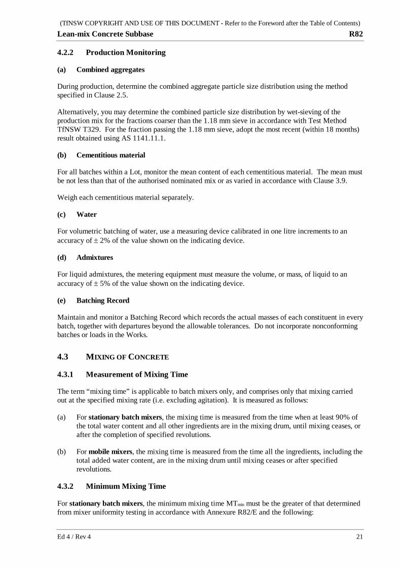
4.2.2 Production Monitoring
(a) Combined aggregates
During production, determine the combined aggregate particle size distribution using the method specified in Clause 2.5.
Alternatively, you may determine the combined particle size distribution by wet-sieving of the production mix for the fractions coarser than the 1.18 mm sieve in accordance with Test Method TfNSW T329. For the fraction passing the 1.18 mm sieve, adopt the most recent (within 18 months) result obtained using AS 1141.11.1.
(b) Cementitious material
For all batches within a Lot, monitor the mean content of each cementitious material. The mean must be not less than that of the authorised nominated mix or as varied in accordance with Clause 3.9.
Weigh each cementitious material separately.
(c) Water
For volumetric batching of water, use a measuring device calibrated in one litre increments to an accuracy of ± 2% of the value shown on the indicating device.
(d) Admixtures
For liquid admixtures, the metering equipment must measure the volume, or mass, of liquid to an accuracy of ± 5% of the value shown on the indicating device.
(e) Batching Record
Maintain and monitor a Batching Record which records the actual masses of each constituent in every batch, together with departures beyond the allowable tolerances. Do not incorporate nonconforming batches or loads in the Works.
4.3 MIXING OF CONCRETE
4.3.1 Measurement of Mixing Time
The term “mixing time” is applicable to batch mixers only, and comprises only that mixing carried out at the specified mixing rate (i.e. excluding agitation). It is measured as follows:
(a) For stationary batch mixers, the mixing time is measured from the time when at least 90% of the total water content and all other ingredients are in the mixing drum, until mixing ceases, or after the completion of specified revolutions.
(b) For mobile mixers, the mixing time is measured from the time all the ingredients, including the total added water content, are in the mixing drum until mixing ceases or after specified revolutions.
4.3.2 Minimum Mixing Time
For stationary batch mixers, the minimum mixing time MTmin must be the greater of that determined from mixer uniformity testing in accordance with Annexure R82/E and the following:

(TfNSW COPYRIGHT AND USE OF THIS DOCUMENT - Refer to the Foreword after the Table of Contents) R82 Lean-mix Concrete Subbase
22 Ed 4 / Rev 4
(a) stationary twin-shaft mixers: not be less than 30 seconds plus 5 seconds for each cubic metre (or part thereof);
(b) all other stationary batch mixers: not be less than 54 seconds plus 6 seconds for each cubic metre (or part thereof).
Up to 10% of the remaining total water content for the authorised nominated mix may be added after the defined mixing time, and the mixing time increased as follows:
(i) stationary twin-shaft mixers: a minimum of 15 seconds of mixing must be provided after the final addition of water;
(ii) all other stationary batch mixers: a minimum of 30 seconds of mixing must be provided after the final addition of water.
For mobile mixers, the minimum mixing time MTmin after charging must be the greater of that shown on the mixer identification plate and 3.0 minutes.
Provide the full period of mixing at either the testing station or the point of placement. Ignore all other mixing and agitation for the purpose of assessing the actual mixing time for a specific batch.
4.3.3 Maximum Mixing Time
The maximum mixing time is 5 minutes for twin-shaft and split-drum mixers, and 10 minutes for all other mixer types.
4.3.4 Admixture Addition
Detail in the PROJECT QUALITY PLAN how admixtures will be incorporated in the mix in accordance with the requirements of this Specification.
Incorporate the admixtures in accordance with the manufacturer’s instructions, and by a method which ensures that no adverse interaction occurs.
4.3.4.1 Incorporation During Initial Batching
Prior to their mixing with other constituent materials, dilute the admixtures separately and thoroughly in the mixing water by either one of the following methods:
(a) addition into the water weigh hopper; or
(b) direct introduction into the water feed line during water batching.
4.3.4.2 Addition into Mobile Mixer After Completion of Batching
Immediately after addition of admixtures, operate the mixing mechanism at the designated mixing speed for not less than 30 revolutions or for such additional time as may be necessary to re-establish uniformity of the mix, except that if assurance is not available that the batch was initially mixed for 55 revolutions, re-mix the adjusted batch for a minimum of 55 revolutions.
4.3.5 Discharge
For batch mixers, after the completion of batching, the entire batch of concrete must be discharged from the mixer before any further charging takes place, with the exception of conforming retempering.

(TfNSW COPYRIGHT AND USE OF THIS DOCUMENT - Refer to the Foreword after the Table of Contents) Lean-mix Concrete Subbase R82
Ed 4 / Rev 4 23
4.3.6 Hold Point
HOLD POINT
Process Held: Production of concrete for paving (including paving trial).
Submission Details: Results demonstrating conformity of mixer uniformity as per Annexure R82/E.
Release of Hold Point: The Principal will consider the submitted results, within 2 working days of receipt of the results, prior to authorising the release of the Hold Point.
4.4 TRANSPORT OF CONCRETE
4.4.1 Batch Delivery Docket
Provide with each batch of concrete an identification certificate (delivery docket) which is pre-numbered and issued sequentially in accordance with the order of batching. This certificate must record the details required to establish the time of completion of batching as defined in Clause 1.3.1.
Depending on the mixer and transport types, this may require the recording of times for charging, and/or mixer discharge and/or slump adjustment.
Detail in the PROJECT QUALITY PLAN how the identification certificate will be monitored for compliance with the batching requirements of this Specification.
4.4.2 Addition of Material After Batching
Any addition of water which occurs after the completion of batching (refer Clause 1.3.1 for definition of “completion of batching”) must be in accordance with Clause 4.6.
Any addition of admixture which occurs after the completion of batching must be in accordance with Clause 4.3.4.
No other materials are allowed to be added to a mixed batch before its complete discharge. Do not incorporate concrete remnants from previous loads into the Works.
4.4.3 Transport of Mixes for Manual Paving
Use agitator vehicles to deliver concrete which will be placed manually, except that material transfer placers and tipper trucks may be used where haul lengths are such that segregation does not occur, and compaction and finishing of the mix is not compromised.
4.5 CONSISTENCE (SLUMP) OF CONCRETE
4.5.1 General
Test consistence of concrete by the slump test in accordance with AS 1012.3.1, within 40 minutes of the completion of batching.
Record all slump test results, whether conforming or otherwise.

(TfNSW COPYRIGHT AND USE OF THIS DOCUMENT - Refer to the Foreword after the Table of Contents) R82 Lean-mix Concrete Subbase
24 Ed 4 / Rev 4
4.5.2 Sampling Method
Sample as follows:
(a) For concrete delivered by tipper trucks, obtain a composite test sample in accordance with AS 1012.1 Clause 7.3. Take the sample before discharge from the truck using a shovel or scoop. Exclude the top 100 mm of concrete.
(b) For concrete delivered by agitators, obtain an individual sample in accordance with AS 1012.1 Clause 7.2.2.
4.5.3 Criteria for Conformity
The slump must be within the following limits from the nominated slump:
(a) slipformed concrete: ± 10 mm;
(b) fixed-formed concrete: ± 15 mm.
For any sample, if the measured slump is not within the specified limits, immediately carry out one repeat test from another portion of the same sample. If the result from the repeat test falls within the specified limits, the concrete represented by the sample is accepted as conforming.
If the result from the repeat test falls outside the specified limits, deal with the concrete delivered as follows:
(i) For concrete delivered by tipper trucks, the concrete is deemed to be nonconforming.
(ii) For concrete delivered by agitators, the batch may be re-mixed and re-tested within a limit of 40 minutes from the completion of batching. If desired, it may be retempered in accordance with the conditions stated in Clause 4.6.
Do not incorporate concrete which is nonconforming in relation to consistence into the Works.
4.5.4 Minimum Frequency of Routine Testing
4.5.4.1 Tipper Delivery
(a) For initial daily slumping, test every load before discharge until there is 8 consecutive conforming loads. Calculate the standard deviation (SD) of these 8 loads.
If SD is less than or equal to 8.0 mm, proceed in accordance with item (b) below.
If SD is greater than 8.0 mm, continue slumping every load until any 8 consecutive loads have a SD less than or equal to 8.0 mm.
(b) For process slumping, test every fourth load. Visually check every intermediate load before discharge, and test for slump any load which appears, in the opinion of either party, to be nonconforming.
Allow visual assessment only by the testing staff, and only at the testing station.
Record visual checks as, for example, V30 and V40 for Visual 30 mm and 40 mm respectively.
If a nonconforming slump is measured, carry out slump tests on all loads thereafter (before discharge) until the SD of 6 consecutive loads is less than or equal to 8 mm, at which time testing may revert to each fourth load.

(TfNSW COPYRIGHT AND USE OF THIS DOCUMENT - Refer to the Foreword after the Table of Contents) Lean-mix Concrete Subbase R82
Ed 4 / Rev 4 25
Additionally, carry out slump test on every load from which samples are taken for other tests on the concrete or its constituents.
4.5.4.2 Agitator Delivery
For initial daily slumping, test every load before discharge until there are 4 consecutive conforming batches. Thereafter, test every alternate batch for slump.
Carry out additional slump tests as required in accordance with the provisions for retempering in Clause 4.6.
Additionally, carry out slump test on every load from which samples are taken for other tests on the concrete or its constituents.
4.6 RETEMPERING
For concrete which is delivered by other than agitator, do not add water or any other ingredient to the mixed batch.
Concrete which is delivered by agitator may be retempered in accordance with the following conditions:
(a) Retempering is allowed only within 40 minutes of the completion of batching.
(b) Retemper only in the presence of your representative who has been previously nominated to the Principal for this purpose.
(c) Retemper only at the batch plant, the testing station, or the point of placement.
(d) Immediately after retempering, re-mix the batch at the designated mixing speed for not fewer than 30 revolutions or for such additional time as may be necessary to re-establish uniformity of the mix.
(e) Record the quantity of added water on the identification certificate for that batch. If water is added after the commencement of discharge, record the estimated remaining quantity of concrete at that time.
(f) Immediately after condition (d) has been satisfied, test the slump for conformity.
(g) Mould test cylinders for compressive strength from the retempered mix, in accordance with this Specification. These cylinders are additional to the routine testing requirements.
Detail in the PROJECT QUALITY PLAN how concrete supply will be monitored for conformity with these retempering provisions.
4.7 FORMING TIME
4.7.1 Maximum Forming Time
Determine the maximum forming time (refer Clause 1.3.1 for definition of “forming time”) for each authorised nominated mix, with consideration of the prevailing weather conditions and concrete temperature.
Detail in the PROJECT QUALITY PLAN the procedure to determine the maximum forming time.

(TfNSW COPYRIGHT AND USE OF THIS DOCUMENT - Refer to the Foreword after the Table of Contents) R82 Lean-mix Concrete Subbase
26 Ed 4 / Rev 4
4.7.2 Actual Forming Time
Monitor the actual forming time, and record the actual forming time for any load exceeding:
(a) 90 minutes for air temperatures less than 30°C;
(b) 60 minutes for air temperatures greater than or equal to 30°C.
Subbase constructed from such loads may be accepted if the compressive strength of cores taken from the section of subbase constructed with the specific load are conforming. Record the specific location of the load placed in the Works.
4.8 AIR CONTENT OF CONCRETE
4.8.1 General
For mixes that contain an air-entraining agent, test for air content in accordance with AS 1012.4.2 for conformity with Clause 3.6.1.
4.8.2 Frequency of Testing
Test daily at the following minimum frequency:
(a) one per load until 3 consecutive conforming results are obtained; and thereafter
(b) one per 50 m3 until 4 consecutive conforming results are obtained; and thereafter
(c) one per 200 m3 for the remainder of the day.
The frequency reverts to that specified under item (a) if a nonconforming result is obtained at any stage of testing.
4.8.3 Criteria for Conformity
For any sample, if the measured air content is not within the limits specified, immediately carry out one repeat test from another portion of the same sample. The concrete represented by the sample is accepted as conforming if the value obtained from the repeat test falls within the specified limits.
4.8.4 Use of Concrete With Nonconforming Air Content
Air entrained concrete with an air content higher than the specified range is nonconforming and must not be used in the Works.
Air entrained concrete with an air content of less than the specified range is nonconforming. However, subbase constructed from such concrete may be accepted as part of the Works if the compressive strength of cores taken from the section of the subbase constructed with the specific load is conforming.
This testing is in addition to routine random sampling, unless that particular load has been chosen in the random selection process.

(TfNSW COPYRIGHT AND USE OF THIS DOCUMENT - Refer to the Foreword after the Table of Contents) Lean-mix Concrete Subbase R82
Ed 4 / Rev 4 27
5 SUBGRADE BEAM
5.1 GENERAL
5.1.1 Sequence
Construct the subgrade beam prior to the placing of the LCS.
5.1.2 Location and Dimensions
Provide subgrade beams below the LCS at the locations shown on the Drawings. The subgrade beam must extend to the full length of the joint, unless shown otherwise on the Drawings.
5.1.3 Excavation
Excavate for the subgrade beam to the dimensions and levels shown on the Drawings. The top of the subgrade beam must be level with the top of the Selected Material Zone (SMZ).
Remove all loose material and trim the vertical faces to neat edges. Where required, compact the bottom of the excavation to the same degree of compaction as that of the adjacent undisturbed material.
Repair any holes in the SMZ adjacent to the subgrade beam and compact the SMZ to provide a smooth and dense surface at the correct level.
5.2 STEEL REINFORCEMENT
HOLD POINT
Process Held: Placing of concrete for subgrade beam.
Submission Details: Certificate of conformity for installation of steel reinforcement.
Release of Hold Point: The Principal will consider the submitted documents and may inspect the work prior to authorising the release of the Hold Point.
5.2.1 General
Steel reinforcement must comply with Clause 2.10.
Store reinforcement above the ground surface and protect it from damage and deterioration due to exposure.
Steel reinforcement placed in the Works must be free from loose or thick rust, grease, tar, paint, oil, mud, mortar or any other coating, or any other condition that would impair its bond to the concrete or its performance within the concrete member.
5.2.2 Cutting and Bending
Cut and bend steel reinforcement to the dimensions and shapes as shown on the Drawings.

(TfNSW COPYRIGHT AND USE OF THIS DOCUMENT - Refer to the Foreword after the Table of Contents) R82 Lean-mix Concrete Subbase
28 Ed 4 / Rev 4
The nominal internal diameter of a reinforcement bend is taken as the external diameter of the pin around which the reinforcement is bent. The diameter of the pin must not be less than five times the bar diameter.
Do not use steel reinforcement with kinks or bends not shown on the Drawings. Do not bend or straighten steel reinforcement in a manner that will damage the material.
5.2.3 Chair Support
Support reinforcement at the required positions using concrete, plastic or wire chairs. The chairs must be sufficiently wide at their base to avoid overturning. Do not use timber or pieces of aggregate to support reinforcement. Do not use a support system which is likely to impede compaction of the enveloping concrete.
Place the chairs at spacings such that during placing and compaction of the concrete, the permanent deflection or displacement of the reinforcement is no more than 2 mm from its required position.
The mass of steel reinforcement supported by any one chair must not exceed 10 kg. Chairs must be capable of supporting 200 kg mass without permanent distortion in excess of 2 mm.
Secure reinforcement in place by wiring the bars and/or fabric together with annealed steel wire having a diameter of not less than 1.2 mm.
5.2.4 Laps
Unless shown otherwise on the Drawings, the minimum length of lapped splices is:
(a) Grade 500: 35 bar diameters;
(b) Grade 250: 25 bar diameters;
(c) Hard-drawn wire: 45 bar diameters.
The ends of bars forming a lapped splice must be securely wired together in at least two places.
For reinforcing fabric, measure splices as the overlap between the outermost wire in each sheet of fabric transverse to the direction of splice. This overlap must not be less than the pitch of the transverse wires plus 25 mm.
5.3 CONCRETE
5.3.1 Supply
The concrete supplied for subgrade beams must either:
(a) conform to Specification TfNSW R83 (except for flexural strength requirements and air content); or
(b) be N32 concrete in accordance with AS 1379, with nominal maximum aggregate size of 20 mm and slump within the range of 50 mm to 80 mm at the point of placement.
Mix and deliver the concrete in accordance with AS 1379, but as amended by Clause 4 of this Specification.

(TfNSW COPYRIGHT AND USE OF THIS DOCUMENT - Refer to the Foreword after the Table of Contents) Lean-mix Concrete Subbase R82
Ed 4 / Rev 4 29
5.3.2 Placing and Finishing
Place and compact the concrete in accordance with Clause 6, and finish it with a steel float to produce a smooth surface, free of any texture.
5.3.3 Compressive Strength
Determine the compressive strength at 7 days in accordance with AS 1012.9 using one pair of moulded specimens for each subgrade beam pour. The compressive strength at 7 days must not be less than 16.0 MPa.
5.4 CURING AND PROTECTION FROM DAMAGE
5.4.1 Curing
Provide curing to the top surface of the subgrade beam in accordance with Clause 6.10 either by application of curing compound or by wet curing before placing the subbase.
Maintain the curing for a minimum of 7 days after placing of concrete for the subgrade beam.
Plastic covers may be used for curing, provided that they form a continuous barrier against loss of moisture and are fully secured around all edges to maintain a moist environment over the full mass of concrete, as evidenced by the presence of moisture on the underside of the covers.
5.4.2 Protection from Damage
Protect the subgrade beam from damage by plant, motor vehicles and the paving operation.
Do not allow vehicular traffic to traverse over the subgrade beam until it has achieved the compressive strength of 16.0 MPa specified in Clause 5.3.3.
6 SUBBASE CONCRETE PAVING
6.1 GENERAL
HOLD POINT
Process Held: Paving of LCS (including paving trial).
Submission Details: Schedule of underlying surface levels and relevant nonconformity report.
Release of Hold Point: The Principal will consider the submitted documents, including the proposed disposition to any nonconformity, prior to authorising the release of the Hold Point.
Place, spread and finish concrete in such manner as to:
(a) avoid segregation or loss of materials;
(b) avoid premature stiffening;
(c) produce a uniformly dense and homogeneous product throughout the subbase layer.

(TfNSW COPYRIGHT AND USE OF THIS DOCUMENT - Refer to the Foreword after the Table of Contents) R82 Lean-mix Concrete Subbase
30 Ed 4 / Rev 4
6.1.1 Underlying Surface
The surface on which the LCS is to be placed must be clean and free of loose or foreign matter, including loose sealing aggregate, and must not hold ponded water. At the time of paving, it must be in a condition which minimises the absorption of mortar and water from the LCS.
6.1.2 Slab Anchor
During construction of the LCS, make allowance for the construction of base slab anchors (not part of the scope of this Specification) at the locations shown on the Drawings.
6.1.3 Traceability
Maintain records showing the location of each load of concrete in the finished work, in accordance with TfNSW Q. The method of traceability must be sufficiently accurate to enable subsequent identification of specific loads for examination and/or testing.
Detail in the PROJECT QUALITY PLAN the method of traceability.
6.2 CONCRETING PERSONNEL
6.2.1 General
For concrete paving, include in the PROJECT QUALITY PLAN the name of the Paving Supervisor with details of qualification(s) and experience in concrete paving.
6.2.2 Paving Supervisor
The Paving Supervisor must hold a TfNSW Concrete Paving Crew Grey Card and have suitable qualification(s) in concrete paving and must be present during all stages of the paving operations until implementation of the curing regime.
Paving operations include, but not be limited to, the following activities:
(a) establishment of stringlines;
(b) fixed form placement;
(c) placing and fixing reinforcement:
(d) receiving and placing concrete;
(e) operation of slipform pavers or vibrating screeds;
(f) compaction, finishing, texturing, curing, debonding and early age protection of concrete.
6.2.3 Paving Crew
In addition to the Paving Supervisor, at least half of the remaining crew involved in a paving operations, must hold a TfNSW Concrete Paving Crew Grey Card.

(TfNSW COPYRIGHT AND USE OF THIS DOCUMENT - Refer to the Foreword after the Table of Contents) Lean-mix Concrete Subbase R82
Ed 4 / Rev 4 31
HOLD POINT (TfNSW Concrete Paving Crew Grey Card)
Process Held: First LCS paving in the Works including paving trial.
Submission Details: At least two weeks prior to the first LCS paving, submit to the Principal the names of the personnel who will be involved in LCS paving operations; which of these persons hold a TfNSW Concrete Paving Crew Grey Card; and corresponding evidence of this.
At least four working hours prior to LCS paving, submit to the Principal a statement stating that at least half of the personnel who will be involved in LCS paving operations hold a TfNSW Concrete Paving Crew Grey Card.
Release of Hold Point: The Principal will verify that at least half of the personnel who will be involved in the LCS paving operations hold a TfNSW Concrete Paving Crew Grey Card prior to authorising the release of the Hold Point.
6.3 TEMPERATURE AND WEATHER CONDITION
6.3.1 Concrete Temperature
Measure and record concrete temperature at the point of discharge in accordance with ASTM C1064M.
Do not place concrete in the Works if its temperature at the point of discharge from transport vehicles is less than 10°C or more than 32°C, except that when the diurnal air temperature changes are greater than or equal to 20°C, the upper limit of temperature of concrete to be placed in the Works is 30°C.
6.3.2 Air Temperature
Measure and record the air temperature outdoors in the shade at the paving site, but remote from artificial influences such as machinery exhaust outlets.
Monitor the air temperature at intervals not exceeding 30 minutes. Stop concrete batching when the air temperature reaches 32°C and is rising.
Do not place concrete in the Works when the air temperature is below 5°C or above 35°C.
6.3.3 Rain
Do not place concrete in the Works during rain or when rain appears imminent.
6.4 SLIPFORM (MECHANICAL) PAVING
6.4.1 General
Where practicable, carry out paving by the slipform method.
The unsupported longitudinal edge produced must maintain its shape and must not sag or tear.
At locations where the paver is unable to fully compact and finish the concrete (such as, but not confined to, transverse construction joints), use supplementary fixed-form paving methods in accordance with Clause 6.5.

(TfNSW COPYRIGHT AND USE OF THIS DOCUMENT - Refer to the Foreword after the Table of Contents) R82 Lean-mix Concrete Subbase
32 Ed 4 / Rev 4
6.4.2 Paving Equipment
The mechanical paver must spread, compact, screed and finish the freshly placed concrete so as to produce a dense and homogeneous slab with a smooth uniform finish requiring minimum hand finishing.
The slipform paver must be a self-propelled machine and must include the following features:
(a) an automatic control system with a sensing device to control line and level to the specified tolerances;
(b) means of spreading the mix uniformly and regulating the flow of mix to the vibrators and conforming plate without segregation of the components;
(c) internal vibrators capable of compacting the full depth of the concrete to produce a dense and homogeneous slab with a smooth uniform finish requiring a minimum of hand finishing;
(d) capability of paving to the widths and depths shown on the Drawings.
Provide in the PROJECT QUALITY PLAN details of the slipform paver.
For each of the proposed slipform paving configurations, nominate the following parameters in the PROJECT QUALITY PLAN:
(i) maximum paving speed (i.e. instantaneous, not average);
(ii) target (optimum) paving speed;
(iii) vibrator spacing, frequency and amplitude, and ranges thereof;
(iv) gross operating mass per linear metre of paving width.
Limit the gaps under side-forms such that the specified systematic vibration and compaction can be achieved throughout the slab with only minimal mortar loss.
6.4.3 Maintenance
Regularly inspect and service the paver so that it is maintained at all times in full operating condition consistent with the manufacturer’s specifications. Monitor key items such as vibrators and sensors throughout the paving process.
Implement a system which can provide an indication of any malfunction of each individual vibrator. Document the system in the PROJECT QUALITY PLAN.
Maintain the supporting surface for the tracks of the paver, curing machine and any other equipment in the paving and curing trains in a smooth and firm condition.
6.4.4 Continuous Uniform Paving
Plan the work, and coordinate the delivery, spreading and paving activities to optimise the continuous and uniform progress of the paver and to minimise discontinuities in the work.
Record details of any interruptions to the progress of the paver, including the reason, location, and duration.
6.4.5 Excessive Bleed Water
If excessive bleed water occurs, such that it flows over the slab edge, stop paving until the consistence of the mix is adjusted to prevent such flow or until the mix is redesigned.

(TfNSW COPYRIGHT AND USE OF THIS DOCUMENT - Refer to the Foreword after the Table of Contents) Lean-mix Concrete Subbase R82
Ed 4 / Rev 4 33
6.5 FIXED-FORM (MANUAL) PAVING
6.5.1 General
Detail in the PROJECT QUALITY PLAN the equipment and methods to be used for placing, spreading and finishing the concrete.
6.5.2 Formwork
Design and construct the formwork so that it is braced in a substantial and unyielding manner.
Debond the formwork so that it can be removed without damaging the concrete.
Set the formwork up such that the screeding surface will be within the tolerances of the specified levels of the finished LCS surface.
Limit gaps in formwork such that the specified systematic vibration and compaction can be achieved throughout the slab with only minimal mortar losses.
6.5.3 Placing and Compacting – Internal Vibrators
Deposit and spread the concrete uniformly and without segregation within the formwork by means other than vibration.
Compact the concrete using internal vibrators. Establish and document suitable vibrator operating parameters for the specific site conditions using systematic spacing and durations to achieve a homogeneous slab with uniform and thorough compaction.
Detail in the PROJECT QUALITY PLAN the size and number of vibrators and pattern and spacing of vibrator insertions.
Internal vibrators used must have the following operating parameters:
(a) a minimum diameter of 50 mm;
(b) operating at a frequency of between 8,000 and 12,000 vibrations/minute (130 – 200 Hz).
The number of working internal vibrators in use during a concrete pour must be not less than one for each 10 m3 of concrete placed per hour. For paving widths in excess of 2.5 m, use a minimum of two vibrators. The number of standby vibrators must be not less than one fourth of the number in use, with a minimum of one.
6.5.4 Levelling, Compacting and Finishing – Vibrating Screed
Following internal vibration, compact and finish the slab by at least two passes of a hand-guided vibratory screed with the following operating parameters:
(a) traverse the full width of the slab on each pass;
(b) constructed of tubular steel trusses or rigid metal and/or timber;
(c) operating at a frequency of between 3,000 and 6,000 vibrations/minute (50 – 100 Hz) and a minimum amplitude of 0.3 mm.
Maintain a suitable head of concrete in front of the screed over its whole length for uniform transmission of vibration into the slab, to produce a dense and homogeneous slab with a surface finish that requires minimum hand finishing.

(TfNSW COPYRIGHT AND USE OF THIS DOCUMENT - Refer to the Foreword after the Table of Contents) R82 Lean-mix Concrete Subbase
34 Ed 4 / Rev 4
Do not use power trowelling on the surface.
6.6 PAVING IN TRANSITION ZONES
For transition zones, use methods of placing which will ensure adequate compaction of the concrete.
Provide the following details in the PROJECT QUALITY PLAN:
(a) proposed technique for paving at transverse construction joints, for both slipform and fixed-form paving, at both the start and finish of paving runs;
(b) length of paving run between a transverse construction joint and the point of effective slipform vibration, at both the start and finish of paving runs;
(c) size and number of manual vibrators;
(d) spacing and duration of vibrator insertions in the concrete;
(e) method of side forming to prevent edge slump;
(f) equipment type and its method of use to provide surface vibration.
6.7 JOINTS AND EDGES
6.7.1 General
Construction joints do not need to be scabbled or corrugated. The first-placed face must be dense, fully compacted, and be free from honeycombing and re-entrant angles.
Where a joint is nonconforming or its edge is damaged, it must first be reinstated or repaired and allowed to set before new concrete for the adjoining section is placed.
Unless shown otherwise on the Drawings, slabs formed by the joints (both transverse and longitudinal) must comply with the minimum dimensions or corner angles stated in Table R82.9.
Table R82.9 – Minimum Dimensions or Corner Angles of Slab
Description Minimum Value
Slab length (m) 1.5 (1)
Slab width (m) 1.0 (2)
Corner angle (°) 70 (3)
Notes: (1) measured parallel to the control line (2) measured orthogonal to the control line (3) measured in plan view
6.7.2 Transverse Construction Joints
Provide transverse construction joints at discontinuities in the placement of concrete as determined by your paving operations.
Their locations must:

(TfNSW COPYRIGHT AND USE OF THIS DOCUMENT - Refer to the Foreword after the Table of Contents) Lean-mix Concrete Subbase R82
Ed 4 / Rev 4 35
(a) not be located within 0.2 m from the outside edge of subgrade beams under Type 14 (i.e. P14/C14/J14/F14) isolation joints in the overlying concrete base;
(b) not be located within 0.5 m from Type 15 (i.e. P15/C15/J15/F15) isolation joints in the overlying concrete base;
(c) be located at a minimum of 0.3 m from the planned location of Type 8 (i.e. P8/F8) joints in the overlying concrete base at roundabouts.
(For details of joint types, refer to TfNSW Internet website Standard Drawings – Concrete Pavement – Construction, available at: http://www.rms.nsw.gov.au/business-industry/partners-suppliers/document-types/standard-drawings/pavement.html)
Transverse joints must be:
(i) continuous over the full paving width, without steps or offsets in any axis, so that along the line of the joint, it does not deviate by more than 20 mm from a 3 m straightedge nor by more than 10 mm from a 0.3 m straightedge;
(ii) constructed at 90° to the longitudinal joints with a butt (flat) joint face which is orthogonal (± 10°) to the finished top surface of the LCS.
6.7.3 Longitudinal Construction Joints
There is no upper limit on the width of LCS which may be constructed between longitudinal joints and/or edges. The minimum dimensions and corner angles of the slabs must however comply with Table R82.9.
Where such joints are required by your placing methods, their locations must comply with the following:
(a) Under concrete bases:
within 0.1 m to 0.4 m offset from a longitudinal joint in the base layer, unless shown otherwise on the Drawings, except that, where a crown exists in the base layer, any underlying longitudinal crown joint in the subbase must be constructed within 0.1 m of the plan location of the longitudinal crown joint in the base, unless shown otherwise on the Drawings.
(b) Under asphalt bases:
within 0.25 m offset from a design lane line.
The joint locations must not deviate from the nominated position at any point by more than 25 mm.
Longitudinal joints must:
(i) along the line of joint, not deviate horizontally by more than 20 mm from a 3 m straightedge placed along the joint, after due allowances for any planned curvature, nor by more than 10 mm from a 0.3 m straightedge;
(ii) be orthogonal (± 10°) to the finished top surface of the LCS;
(iii) along the line of joint, not deviate vertically by more than 3 mm from a 0.3 m straightedge placed along the joint.

(TfNSW COPYRIGHT AND USE OF THIS DOCUMENT - Refer to the Foreword after the Table of Contents) R82 Lean-mix Concrete Subbase
36 Ed 4 / Rev 4
6.7.4 Subbase Width and Outer Edges
Unless shown otherwise on the Drawings, the LCS must be constructed wider than the plan position of the overlying base by the following amounts (with a tolerance of ± 25 mm):
(a) 50 mm, where the overlying base is concrete base;
(b) 25 mm, for all other base types.
Outer edges must be constructed orthogonal to the finished top surface of the subbase with a tolerance of ± 10°, be dense, fully compacted, and free of honeycombing and re-entrant angles.
6.7.5 Inspection
Inspect each joint and edge within 24 hours of its construction, and again before paving of the next adjoining section of the LCS. If nonconformity is detected, implement Corrective Action before proceeding with the paving of the adjoining section.
6.8 PREVENTION OF MOISTURE LOSS
6.8.1 Meteorological Data
Detail in the PROJECT QUALITY PLAN what meteorological or other data will be collected, how such data will be used and what measures will be taken to restrict the evaporation of water from the concrete surface and to limit the incidence of plastic shrinkage cracking.
6.8.2 Determination of Evaporation
Determine the evaporation using Figure R82.2.
6.8.3 Application of Evaporation Retarder
If an evaporation retarder is used to restrict the evaporation of water, apply it as a fine uniform spray. Carry out any subsequent finishing operations in such manner that does not incorporate the evaporation retarder into the surface mortar.
Detail in the PROJECT QUALITY PLAN regular inspections of the plastic concrete to monitor the effectiveness of the adopted procedures.

(TfNSW COPYRIGHT AND USE OF THIS DOCUMENT - Refer to the Foreword after the Table of Contents) Lean-mix Concrete Subbase R82
Ed 4 / Rev 4 37
Notes: The graph shows the effects of air temperature, humidity, concrete temperature and wind velocity together on the rate of evaporation of water from freshly placed and unprotected concrete. An example follows: With air temperature at 27°C, relative humidity at 40%, concrete temperature at 27°C, and a wind velocity of 26 km/h, the rate of evaporation will be 1.6 kg/m2/h. To determine the evaporation rate from the graph, enter the graph at the air temperature (in this case 27°C), and move vertically to intersect the curve for relative humidity encountered (here 40%). From this point, move horizontally to the respective line for concrete temperature (here 27°C). Move vertically down to the respective wind velocity curve (in this case interpolating for 26 km/h) and then horizontally to the left to intersect the scale for the rate of evaporation. (Source: Gelber, S, 1984, “Predict evaporation rate and reduce plastic shrinkage crack”, Concrete International (ACI) v5 n4, 19-22)
Figure R82.2 - Evaporation from Concrete Freshly Placed on Site

(TfNSW COPYRIGHT AND USE OF THIS DOCUMENT - Refer to the Foreword after the Table of Contents) R82 Lean-mix Concrete Subbase
38 Ed 4 / Rev 4
6.9 SURFACE FINISH
6.9.1 General
The paved surface of the LCS must be uniform, dense and compact.
6.9.2 Type of Surface Finish
Where the LCS is to be covered by an asphalt base or granular flexible base, provide a hessian drag or broomed finish.
Where the LCS is to be covered by a sprayed bituminous seal followed by a concrete base, a light hessian drag is optional.
In both cases, the mean texture must not be more than 0.5 mm when tested in accordance with Test Method TfNSW T192 or T240.
6.10 CURING
6.10.1 General
Provide curing to the LCS by spraying curing compound to form a continuous and unbroken film to all exposed surfaces, including the faces of fixed formed joints and sections of slipformed edges which were supported by temporary forms at the time of initial spraying.
The curing compound, when sprayed, must have a uniform consistency.
Detail in the PROJECT QUALITY PLAN the supplier’s recommended procedures for storage and agitation of curing compounds under varying weather conditions in order to maintain uniformity.
6.10.2 Curing Times
Apply the curing compound within 15 minutes of the surface reaching the low-sheen bleed water condition. On fixed-formed surfaces, apply the compound within 30 minutes of stripping. At the time of application, the concrete must be in damp condition.
Maintain the curing membrane intact in a continuous and unbroken membrane for 7 days, or until insitu concrete strength of 4.0 MPa is achieved, whichever occurs first.
6.10.3 Respraying
Make good any damage to the curing membrane by hand spraying the affected area.
Additionally, for a minimum distance of 7 m adjoining the commencement of each paving run, respray with a single application any hardened concrete of age less than 7 days (or 4.0 MPa) that has been trafficked by persons during placement at the construction joint, even though membrane damage may not be apparent.
The cost of any respraying, and of making good any damage to the curing membrane, will be borne by you.

(TfNSW COPYRIGHT AND USE OF THIS DOCUMENT - Refer to the Foreword after the Table of Contents) Lean-mix Concrete Subbase R82
Ed 4 / Rev 4 39
6.10.4 Curing Compound Types
The curing compound type to be used for various overlying base types must comply with Table R82.10.
Table R82.10 - Curing Compound Types
Overlying Base Layer Curing Compound Type (1)
Concrete base - PCP, JRCP, CRCP, SFCP WE
Asphalt base B-HCR or BE binder
Granular flexible base HCR, WHCR, B-HCR or BE binder Legend: WE: wax emulsion HCR: hydrocarbon resin WHCR: water-borne hydrocarbon resin BE: bitumen emulsion B-HCR: blended bitumen and water-borne hydrocarbon resin
Note: (1) The Principal may consider alternative proposals where there will be a long delay before surfacing works, or
where a specialised bonding treatment is proposed. Where a fugitive dye is used, it must be incorporated in the curing compound by the manufacturer.
6.10.5 Equipment
Apply the curing compound in a fine spray by the following means:
(a) for paving widths less than 3.5 m: by hand lance, with either single or multiple nozzles, or by the method stated in item (b) or (c) below;
(b) for paving widths 3.5 m to 4.5 m: by hand lance or spray bar fitted with a minimum of 3 nozzles spaced to give a uniform cover over a minimum width of 1.0 m in a single pass, or by the method stated in item (c) below;
(c) for slipform paving widths greater than 4.5 m: by a mechanical sprayer fitted with a spray bar with multiple nozzles spaced to give a uniform cover for the full paving width in a single pass.
Fit protective hoods to spray bars and lances to reduce the drift of curing compounds to workers and roadside areas and to minimise the effects of wind on the variability in application rate.
Set the spray nozzles to provide an overlap factor (by width measurement) as shown in Figure R82.3. Determine this factor through field trials in accordance with item (iii) below.
where:
W = theoretical coverage
c = overlap factor (≤ 1.0)
Figure R82.3 - Curing Compound Spraying Overlap
For fan nozzles, rotate each nozzle sufficiently about a vertical axis to prevent interference between adjacent fans.

(TfNSW COPYRIGHT AND USE OF THIS DOCUMENT - Refer to the Foreword after the Table of Contents) R82 Lean-mix Concrete Subbase
40 Ed 4 / Rev 4
For mechanical spraying, detail in the PROJECT QUALITY PLAN the procedures to demonstrate the following:
(i) Uniformity of output from each nozzle, including edge sprays (litres per minute per nozzle).
(ii) Parameters and methods to be used to measure and calibrate a uniform output across the full spray width and edges (L/m2).
(iii) Field trials that are proposed in order to develop operating parameters such as nozzle height, spray pressure and the spray overlap factor “c” (as shown in Figure R82.3) and to demonstrate uniform and conforming coverage, including edges.
Determine these parameters before any paving trial (refer Clause 6.11) that requires mechanical curing.
During the paving trial, verify the operating parameters developed under item (iii) above.
6.10.6 Application Rate
Nominate in the PROJECT QUALITY PLAN the method and application rate for applying the curing compound.
The application rate must comply with the following:
(a) For all curing compound other than bitumen emulsion
(i) mechanical spraying:
the rate stated on the test certificate for curing efficiency, but at a minimum of 0.25 L/m2 in a single pass;
(ii) manual spraying:
25% above the rate stated on the test certificate for curing efficiency, but at a minimum of 0.25 L/m2.
(b) For bitumen emulsion binder:
not less than 0.50 L/m2 residual bitumen.
6.10.7 Verification of Application Rate
Verify the curing compound application rate as follows and at the frequency shown in Table R82.11:
(a) Test Method A
Calculate the average application rate from the total measured quantity of compound applied within the area specified in Table R82.11.
(b) Test Method B
Measure the amount of curing compound locally on test mats placed on the pavement at random locations. Use three felt mats per test, each approximately 0.25 m2 in area and placed within an area of 50 m2 on the surface to be treated.

(TfNSW COPYRIGHT AND USE OF THIS DOCUMENT - Refer to the Foreword after the Table of Contents) Lean-mix Concrete Subbase R82
Ed 4 / Rev 4 41
Table R82.11 - Frequency of Testing for Application Rate of Curing Compound
Spraying Method
Test Method Area (1)
Manual A Each paving area of between 500 m2 and 1,000 m2.
A Each paving area up to a maximum of 2,000 m2.
Mechanical
and B During paving trial; and thereafter:
(a) one in every sixth sub-Lot until 3 consecutive conforming results are obtained; then
(b) one in every 50 sub-Lots.
Testing frequency reverts to (b) if a nonconforming result is obtained.
Note: (1) Area may be varied for each test to suit individual circumstances, such as the timing of refilling the curing
compound tank, conditional on the application procedure being homogeneous within each nominated test sub-Lot.
6.10.8 Conformity of Application
The application within a test section is deemed to be conforming if:
(a) the application on the surface is visually uniform and homogeneous;
(b) the losses (by wind or other causes) are insignificant;
(c) all test results obtained in accordance with Table R82.11 are conforming.
For any section at which the application is nonconforming, respray within 6 hours of initial spraying, at an application rate not less than twice the deficiency in the original application.
6.10.9 Wet Curing
In confined spaces, such as tunnels, where the use of curing compounds is considered to be undesirable, cure the LCS for a minimum of 7 days using water curing or plastic covers in accordance with Clause 5.4.1.
6.11 CONCRETE PAVING TRIAL
6.11.1 General
Prior to full scale LCS paving, construct a trial section of LCS using the authorised nominated concrete mix, equipment and methods, and in accordance with the quantity limits stated in Table R82.12.

(TfNSW COPYRIGHT AND USE OF THIS DOCUMENT - Refer to the Foreword after the Table of Contents) R82 Lean-mix Concrete Subbase
42 Ed 4 / Rev 4
Table R82.12 – Quantity Limits for Paving Trial
Parameter Requirements
Slipform Fixed-form
Length of paving trial (1, 2) Minimum 50 m 15 m
Maximum 100 m 50 m
Concrete volume in paving trial Minimum Not applicable 20 m3
Notes: (1) The Principal may accept an extension of the paving trial to a full day of paving if the Contractor has
demonstrated satisfactory paving performance in recent past projects. (2) Construct the trial section(s) in a continuous operation without intermediate construction joints.
Give the Principal at least 5 working days written notice of your intention to commence each paving trial.
If a paving trial is conducted at a paving width of less than 70% of the maximum paving width proposed, the Principal may call for a new trial section prior to paving of sections with widths equal to or greater than 70% of the maximum width proposed
6.11.2 Assessment and Reporting
Assess the concrete mix(es) produced during the trial paving in comparison with that produced in the laboratory during the development of the authorised nominated mix. For the purpose of the comparison, determine the particle size distribution of fresh concrete during the trial paving using wet-sieving in accordance with Clause 4.2.2 for a minimum of 3 loads, at 10%, 50% and 90% of discharge of each load.
Verify the curing compound application rate in accordance with Clause 6.10.7.
Assess the constructed trial pavement for conformity with respect to cracking, core compressive strength, thickness, alignment, levels and surface profile in accordance with Clause 8.
Submit to the Principal a written report containing the results of the paving trial. The report must be in the form of a table showing, as a minimum, the information listed in Annexure R82/H, and attaching the 7-day core compressive strength test results. The 28-day core compressive strength test results do not need to be submitted as part of the report but must be submitted when available later.
Highlight in the report any notable inconsistencies between the mixes produced during the paving trial and that of the authorised nominated mix, and provide comments on any consequential risks that may arise resulting from this.
HOLD POINT
Process Held: Commencement of LCS paving other than trial paving.
Submission Details: Report of paving trial, including relevant test results.
Release of Hold Point: The Principal will inspect the constructed trial pavement and consider the submitted documents within 2 working days of their receipt, prior to authorising the release of the Hold Point.

(TfNSW COPYRIGHT AND USE OF THIS DOCUMENT - Refer to the Foreword after the Table of Contents) Lean-mix Concrete Subbase R82
Ed 4 / Rev 4 43
6.11.3 Acceptance of Trial Section
The trial section will be accepted as part of the Works if it conforms to this Specification.
If the trial section is nonconforming, remove the paved concrete, carry out paving of a new trial section and repeat the evaluation detailed in this Clause.
6.11.4 New Trial Section
The Principal may call for a new trial section at any stage of the Works if:
(a) significant changes are made by you to the equipment, materials, plant or rate of paving;
(b) recurring nonconformities of the concrete subbase occur.
6.12 PROTECTION OF WORK
6.12.1 Temperature
If the temperature at the Site is forecast by the Bureau of Meteorology to fall below 10°C within 24 hours of paving, measure and record surface temperatures for the first 24 hours after paving, at two or more locations within each day’s paving, using purpose-made surface thermometers.
Detail in the PROJECT QUALITY PLAN the procedures and equipment proposed for the protection of concrete from low air temperatures.
Failure to maintain the temperature of the concrete at or above 5°C for the first 24 hours after paving is a nonconformity.
If you propose to use subbase protective covers, obtain the prior written agreement of the Principal to their use if you intend to claim payment under Pay Item R82P5.
6.12.2 Rain
Protect the Works from rain damage. Keep the protective equipment on site ready for use by experienced personnel at short notice.
Detail in the PROJECT QUALITY PLAN the procedures and equipment proposed to protect the concrete from rain damage.
No additional payment will be made for protecting the newly placed LCS from rain damage.
Concrete is nonconforming if:
(a) during transport in tippers, it is exposed to rain creating puddles on the surface of the concrete; or
(b) after discharge on the ground, it is exposed to rain creating puddles which will be mixed into the uncompacted concrete during spreading or paving; or
(c) after paving, it is exposed to rain such that water is incorporated into the surface mortar during finishing operations.
Where paved surfaces have been exposed to rain, assess these surfaces in accordance with the finished surface acceptance criteria.

(TfNSW COPYRIGHT AND USE OF THIS DOCUMENT - Refer to the Foreword after the Table of Contents) R82 Lean-mix Concrete Subbase
44 Ed 4 / Rev 4
6.12.3 Trafficking of Subbase
Monitor and minimise trafficking of the LCS, including foot traffic, to avoid damage to the curing compound.
Do not allow personnel or equipment except for those associated with essential inspection and testing to traffic the LCS until an insitu compressive strength of 4.0 MPa has been reached.
HOLD POINT
Process Held: Trafficking of LCS.
Submission Details: Insitu compressive strength test results of the subbase.
Release of Hold Point: The Principal will consider the submitted results, within 2 working days of receipt of the results, prior to authorising the release of the Hold Point.
Thereafter, only foot traffic, vehicles with a gross mass of less than 2.0 tonnes, and any construction equipment necessary for the following operations are permitted to traffic the LCS:
(a) surface debonding/bonding treatment and spall treatment;
(b) base paving, but only for a distance of up to 300 m immediately ahead of the base paver (not part of the scope of this Specification);
(c) slipform paving tracks associated with paving of adjoining subbase;
(d) construction of no fines concrete (NFC) layer under the kerbs, but only within 300 mm from the nearest edge of the NFC layer;
(e) coring, and backfilling of core holes.
Rectify any damage caused to the LCS resulting from your operations, in a way which produces a dense, homogeneous subbase with the specified surface finish, at your own cost.
6.13 SURFACE DEBONDING/BONDING TREATMENT
6.13.1 General
Where the overlying base layer is concrete, apply debonding treatment to the subbase to prevent an interlayer bond.
Where the overlying base layer is part of a flexible pavement (such as asphalt), apply bonding treatment to the LCS to provide a strong interlayer bond.
This debonding/bonding treatment is in addition to the curing treatment applied under Clause 6.10.

(TfNSW COPYRIGHT AND USE OF THIS DOCUMENT - Refer to the Foreword after the Table of Contents) Lean-mix Concrete Subbase R82
Ed 4 / Rev 4 45
HOLD POINT
Process Held: Surface debonding/bonding treatment.
Submission Details: At least 5 working days before commencing surface debonding/bonding treatment, submit the schedule of measured levels and subbase thickness, and any relevant nonconformity report (refer Clause 7.1.3).
Release of Hold Point: The Principal will consider the submitted documents prior to authorising the release of the Hold Point.
6.13.2 Types of Debonding/Bonding Treatments
The types of debonding/bonding treatment to the LCS surface for the different overlying base type must be in accordance with Table R82.13.
Table R82.13 - Debonding/Bonding Treatments
Planned Base Type Treatment Type Material
Concrete base - PCP, CRCP and JRCP
Debonding
BS (1, 3)
Concrete base - SFCP WE (2) or BS (3) or BES (3)
Concrete shoulders - PCP BS (1, 3) or WE (2)
Asphalt base Bonding
BS (3)
Granular flexible base BS (3) Legend: WE: wax emulsion BS: cutback bitumen seal BES: bitumen emulsion seal
Notes: (1) The Principal may approve BES as an alternative under PCP shoulders and in piecemeal construction
where BS is impractical. (2) Wax emulsion must conform to Clause 6.13.6. (3) Bitumen seals (BS and BES) must conform to Clause 6.13.5.
6.13.3 Times for Treatment
Do not apply surface debonding/bonding treatment until:
(a) the LCS has achieved strength of 4.0 MPa (refer Clause 8.3.6);
(b) schedules of LCS levels have been submitted (refer Clause 7.1.3) and disposition of any nonconformities completed (refer Clause 8).
Complete the treatment within 49 days of placement of the LCS, or within 14 days of the achievement of strength conformity under Clause 8.3.6, whichever occurs first.
6.13.4 Surface Preparation and Repair Treatment
Clean the LCS surface of all loose, foreign and deleterious material before applying the surface debonding/bonding treatment.

(TfNSW COPYRIGHT AND USE OF THIS DOCUMENT - Refer to the Foreword after the Table of Contents) R82 Lean-mix Concrete Subbase
46 Ed 4 / Rev 4
Fill spalled areas (with the exception of full-depth cracks) greater than 10 mm deep and 15 mm wide with a low-shrink rapid-hardening cement mortar or a mixture of aggregate and bitumen to provide a surface flush with the LCS surface. The repair material used must adhere to the LCS concrete.
Fill full-depth cracks which have spalled more than 10 mm deep and 15 mm wide with a suitable flexible sealant or a mixture of sand and bitumen to provide a surface flush with the LCS surface.
Detail in the PROJECT QUALITY PLAN the methods for surface preparation and repair treatments.
6.13.5 Cutback Bitumen and Bitumen Emulsion Seals
6.13.5.1 Cutback Bitumen Seal (BS)
Design and apply a cutback bitumen seal complying with Specification TfNSW R106 but as amended hereunder.
The bitumen must be class C170 or C240 complying with TfNSW 3253. The bitumen may be cut back with cutter oil, up to a maximum of 2%. Design the bitumen application rate in accordance with TfNSW R106, with residual bitumen limits of between 0.60 L/m2 (minimum) and 0.80 L/m2 (maximum), measured at 15°C.
Aggregate must be of 7 mm nominal size complying with Specification TfNSW 3151. Susceptibility to aggregate polishing requirements in TfNSW 3151 does not apply. Spread the aggregate at a rate of approximately 250 m2/m3 to provide a mosaic of single stone thickness.
6.13.5.2 Bitumen Emulsion Seal (BES)
Design and apply a bitumen emulsion seal complying with Specification TfNSW R111 but as amended hereunder.
Bitumen emulsion binder must conform to Specification TfNSW 3254. Design the bitumen emulsion application rate in accordance with TfNSW R111, with residual bitumen limits of between 0.60 L/m2 (minimum) and 0.80 L/m2 (maximum), measured at 15°C.
Aggregate must be of 7 mm nominal size complying with TfNSW 3151. Susceptibility to aggregate polishing requirements in TfNSW 3151 does not apply. Spread the aggregate at a rate of approximately 250 m2/m3 to provide a mosaic of single stone thickness.
6.13.6 Wax Emulsion (Under Concrete Base)
Apply wax emulsion debonding treatment at an application rate of not less than 0.20 L/m2. This is in addition to any wax emulsion curing treatment applied in accordance with Clause 6.10.
Apply the wax emulsion before the reinforcing steel for the base is placed.
Wax emulsion must conform to Table R82.3. All other aspects of application and testing must comply with Clause 6.10.
7 SURVEY Carry out survey in accordance with Specification TfNSW G71 and this Specification.

(TfNSW COPYRIGHT AND USE OF THIS DOCUMENT - Refer to the Foreword after the Table of Contents) Lean-mix Concrete Subbase R82
Ed 4 / Rev 4 47
7.1 LEVELS
7.1.1 General
When determining the levels, use a survey staff (or reflector) with flat base of area between 300 mm2 and 4,000 mm2.
Report the levels obtained to the nearest millimetre.
7.1.2 Survey of Underlying Surface Levels
Carry out a survey of the underlying surface levels prior to the commencement of LCS paving. Where the underlying layer has been constructed by others or where the survey is for measurement for payment, the survey of the underlying layer must be a joint survey for determination of payment or deductions.
Take levels of the underlying surface at a spacing of 10.0 m longitudinally and at the transverse offsets shown in Figure R82.4, with a tolerance of 0.5 m.
Where the underlying layer has a sprayed seal over it, take levels on the top of the seal after removal of foreign, or loose material, such as excess aggregate. Alternatively, the subbase bottom levels may be taken as the levels before sealing, plus the average least dimension (ALD) of the cover aggregate as determined in accordance with TfNSW 3151.
7.1.3 Survey of LCS Finished Surface Levels
Carry out a survey of the finished surface levels of the LCS for conformity of levels and thickness within 4 days of placing, unless agreed otherwise with the Principal.
Take levels at the following locations:
(a) at the same plan locations as those surveyed for the levels on the underlying layer under Clause 7.1.2 with a tolerance of 0.5 m;
(b) randomly selected locations at a minimum frequency of at least half the frequency required to comply with item (a) above.
Submit to the Principal schedules of levels showing the measured actual levels and their corresponding design levels, and the difference between the two. Highlight those levels and differences that are out of tolerance, and those locations which were specially surveyed for apparent nonconformity.
Use the following convention for the difference between the actual and design levels:
• where actual levels are above design levels, show the difference as positive;
• where actual levels are below design levels, show the difference as negative.

(TfNSW COPYRIGHT AND USE OF THIS DOCUMENT - Refer to the Foreword after the Table of Contents) R82 Lean-mix Concrete Subbase
48 Ed 4 / Rev 4
Case 1 Slipformed: W ≥ 11.0 Case 2 Slipformed: W ≥ 8.0 Fixed-formed: W ≥ 6.0 Case 3 Slipformed: 4.5 ≤ W < 8.0 Fixed-formed: 4.5 ≤ W < 6.0 Case 4 W ≤ 4.5 For 3.0 < W ≤ 4.5: L = 1.0 For W ≤ 3.0: L = 0.5 Case 5 W ≤ 4.5 For 3.0 < W ≤ 4.5: L = 1.0 For W ≤ 3.0: L = 0.5
Figure R82.4 - Survey Locations Legend:
Location of lane line on base course Location of survey point (see Note (2) below) Alternative location of survey point at other side of lane line (see Note (2) below)
FJ Formed joint or edge
Notes: (1) All dimensions shown in the figure above are in metres. (2) Where an alternative location of survey point is shown (Cases 1 and 2), the Contractor can take survey levels
at either side of the lane line (i.e. at either of the locations marked with “ ” or with “ ”). (3) Survey levels must be taken for both the underlying surface (refer Clause 7.1.2) and the LCS finished surface
(refer Clause 7.1.3). (4) At locations where the distance between a formed edge and the adjacent lane line is varying (i.e. is tapered in
plan view), the survey point will be at a 0.5 m offset from that lane line.
1.5 1.5
FJ FJ Base Subbase
W
0.5 0.5 1.5 1.5
FJ FJ Base Subbase
W
L
FJ Base Subbase
W
Adjoining subbase
0.5 0.5
W
1.5 0.5 0.5 1.5
FJ FJ Base Subbase
L L
FJ FJ Base Subbase
W

(TfNSW COPYRIGHT AND USE OF THIS DOCUMENT - Refer to the Foreword after the Table of Contents) Lean-mix Concrete Subbase R82
Ed 4 / Rev 4 49
7.2 ALIGNMENT
7.2.1 Times
Carry out a survey for conformity of the alignment of the edges and joints within 4 days of placing a sub-Lot of LCS.
7.2.2 Frequency
Survey each outer edge (refer Clause 6.7.4) for alignment conformity at random locations, commencing with the trial paving and thereafter independent of the boundaries to sub-Lots, at a frequency not less than the following:
(a) one reading per 10 m of edge, until five conforming results are recorded; and thereafter
(b) one reading per 50 m of edge.
The survey frequency reverts to item (a) above if nonconformity is detected.
7.3 SURFACE PROFILE
7.3.1 Times
Carry out a survey of the surface profile within 4 days of placing a sub-Lot of LCS, or at the times agreed with the Principal.
7.3.2 Test Method
Determine the surface profile under a 3 m straightedge in accordance with Test Method TfNSW T183. Where the surface is convex, place the straightedge so that the cantilever length does not exceed 0.75 m.
7.3.3 Frequency
Survey for surface profile conformity at random locations, commencing with the trial paving and thereafter independent of the boundaries to sub-Lots, at a frequency of not less than the following:
(a) one reading of longitudinal and transverse surface profile per 10 m of paving run, until 5 conforming results are recorded; and thereafter
(b) one reading of longitudinal and transverse surface profile per 100 m of paving run.
The survey frequency reverts to (a) if nonconformity is detected.
8 CONFORMITY
8.1 TYPES OF CONCRETE CRACKING
8.1.1 Typical Drying Shrinkage Cracking
Typical drying shrinkage cracks comprise full-depth transverse cracks continuous for the full width of the paving run at a spacing of between 2.5 m and 15 m with crack width less than 0.5 mm and cracking step less than 1 mm at any point using a 3 m straightedge.
(TfNSW COPYRIGHT AND USE OF THIS DOCUMENT - Refer to the Foreword after the Table of Contents) R82 Lean-mix Concrete Subbase
50 Ed 4 / Rev 4
Where subbase is placed in a single pass exceeding 6 m width, longitudinal full-depth cracking might also typically occur at the following locations:
(a) single longitudinal full-depth crack in the centre third of the paved width;
(b) multiple longitudinal cracks at a spacing of approximately 4 m and at a minimum distance of 1 m from an edge.
No action is required for typical drying shrinkage cracking.
8.1.2 Typical Plastic Shrinkage and Surface Cracking
Typical plastic shrinkage cracks comprise discrete cracks of less than 500 mm length each and depth less than 50% of the slab thickness, which do not intersect a formed edge. For such cracks, no remedial action is required where debonding/bonding treatment is to be applied, but implement corrective action to minimise recurrence.
Surface cracks are cracks that are less than 0.5 mm deep and are confined to the surface mortar. For such cracks, implement corrective action to minimise recurrence.
8.1.3 Non-typical Cracking
Non-typical cracking is subbase cracking other than the typical cracking described above in Clauses 8.1.1 and 8.1.2. Deal with non-typical cracking in accordance with Clause 8.2.
8.2 CRACK ASSESSMENT
8.2.1 General
Detail in the PROJECT QUALITY PLAN a Crack Assessment Procedure (CAP) for crack assessment of the LCS.
8.2.2 Crack Inspection
Carry out a site inspection jointly with the Principal to determine the types of cracks and their extent, before application of the debonding/bonding treatment, but after compressive strength of 4.0 MPa has been achieved in the LCS.
Conduct the inspection during the following times:
• between 1 October and 31 March: completed before 9:00 am;
• between 1 April and 30 September: completed before 11:00 am.
WITNESS POINT
Process Witnessed: Inspection of LCS and assessment using the CAP in the PROJECT QUALITY PLAN.
Submission Details: At least one working day notice of intention to carry out inspection of LCS and assessment using the CAP.
(TfNSW COPYRIGHT AND USE OF THIS DOCUMENT - Refer to the Foreword after the Table of Contents) Lean-mix Concrete Subbase R82
Ed 4 / Rev 4 51
8.2.3 Crack Map
Where non-typical cracks are present, prepare a crack map showing all cracks including both typical and non-typical cracks, by drawing them on a plan at a scale of 1:100 for the whole paving run. Plot all typical cracks in green and all non-typical cracks in red.
Show in the crack map the associated road chainages, date of inspection, crack widths of the non-typical cracks and crack stepping.
8.2.4 Assessment of Non-typical Cracking
Where non-typical cracks are present, assess the non-typical cracking within a 5 m x 5 m area in accordance with the process shown in Figure R82.5 for non-typical drying shrinkage cracking, and Figure R82.6 for non-typical plastic shrinkage cracking, and identify the required remedial and corrective actions.
HOLD POINT (where non-typical cracks are present)
Process Held: Application of bonding/debonding treatment after crack assessment.
Submission Details: Nonconformity report, including details of investigations to determine cause of non-typical cracking at each location, “to scale” crack maps, paving details such as mix constituents, forming time, moisture condition of the paved surface, ambient temperature at placement and during first 24 hours after placement, curing spray rate and timing of application.
Recommendations for remedial and corrective actions.
Release of Hold Point: The Principal will consider the submitted documents prior to authorising the release of the Hold Point.
In addition, Hold Points apply in accordance with TfNSW Q to the remedial actions not covered by the above Hold Point and to corrective actions.

(TfNSW COPYRIGHT AND USE OF THIS DOCUMENT - Refer to the Foreword after the Table of Contents) R82 Lean-mix Concrete Subbase
52 Ed 4 / Rev 4
Notes: (1) Cumulative crack length is the total length of all non-typical drying shrinkage cracks within a 5 m x 5 m area. (2) Identify required corrective action through a review of your paving process. The review may include details
such as mix constituents, forming time, moisture condition of the paved surface, ambient temperature at placement and during first 24 hours after placement, curing spray rate and timing of application.
(3) Use engineering judgement to identify the required remedial action. Under concrete base, the remedial action may include filling cracks with a low viscosity grout. Under asphalt base, the remedial action may include filling cracks with a low viscosity grout or low viscosity cutback bitumen, application of bituthene tape over the crack, and application of PMB seal in place of conventional seal.
(4) Remedial action is “remove and replace”. Use engineering judgement to identify the areas of LCS to be removed and replaced.
Figure R82.5 – Assessment Process for Non-typical Drying Shrinkage Cracks
Start
Crack width
Corrective action (2)
Corrective action (2)
Cumulative crack length (1)
Remedial (3) and corrective action (2)
< 1.0 mm > 1.0 mm
< 0.5 mm > 0.5 mm
< 4 m > 4 m
< 2 m > 2 m
< 2 m > 2 m
Remove and replace (4), corrective action (2)
Remedial (3) and corrective action (2)
Crack width
Cumulative crack length (1)
Remove and replace (4), corrective action (2) Cumulative
crack length (1)

(TfNSW COPYRIGHT AND USE OF THIS DOCUMENT - Refer to the Foreword after the Table of Contents) Lean-mix Concrete Subbase R82
Ed 4 / Rev 4 53
Notes: (1) Cumulative crack length is the total length of all non-typical plastic shrinkage cracks within the 5 m x 5 m
area. (2) Only where debonding/bonding treatment is to be applied. (3) Identify required corrective action through a review of your paving process. (4) Use engineering judgement to identify the required remedial action.
Figure R82.6 – Assessment Process for Non-typical Plastic Shrinkage Cracks
8.3 CONCRETE COMPRESSIVE STRENGTH
8.3.1 Sub-Lot Delineation
Assess conformity of LCS for compressive strength on the basis of sub-Lots (refer Clause 1.3.1 for definition of sub-Lots).
Treat transition zones as separate sub-Lots in accordance with the following rules:
(a) At each transverse construction joint in slipform work, generate one discrete transition sub-Lot on each side of the joint, each with a length of 3 m, or as nominated otherwise in Clause 6.6.
(b) Where a transition point (refer Clause 1.3.1 for definition of “transition point”) is remote from a transverse construction joint, treat the transition point as if it were a joint (i.e. generate two transition sub-Lots as in item (a) above).
If you choose to define a sub-Lot for a transition zone by a method that is different from items (a) and (b), detail the method in the PROJECT QUALITY PLAN in accordance with Clause 7.5.3 of TfNSW Q. The details must include how the method incorporates the requirements of items (a) and (b).
8.3.2 Test Groups
A test group of cores is defined as a group comprising two cores taken from the LCS which are within a distance of 0.3 m to 1.0 m apart from each other, except that:
(a) if either of the cores has compressive strength of less than 4.5 MPa; or
(b) the difference between the strengths is greater than 1.0 MPa,
then a third core is taken at a distance within 0.3 m to 1.0 m from the others and included in the test group.
The insitu compressive strength of the sub-Lot is the mean (rounded to the nearest 0.1 MPa) of the corrected compressive strengths of all the cores in the particular test group.
Start
Cumulative crack length (1)
< 1 m > 1 m
Remedial (4) and corrective action (3)
Use as is (2), corrective action (3)

(TfNSW COPYRIGHT AND USE OF THIS DOCUMENT - Refer to the Foreword after the Table of Contents) R82 Lean-mix Concrete Subbase
54 Ed 4 / Rev 4
8.3.3 Location and Frequency of Coring
Select the locations for coring at random in accordance with TfNSW Q Annexure Q/L Clause L3 and as set out below.
Take one test group of cores from:
(a) each sub-Lot of slipformed concrete;
(b) each sub-Lot of fixed-formed concrete;
(c) in transition zones, commencing with the trial section, the minimum frequency of coring is as follows:
(i) one group from each sub-Lot until 3 consecutive conforming sub-Lots are obtained; and then
(ii) one group from each third sub-Lot, selected on the basis of time sequence, until 4 consecutive sub-Lots conform; and then
(iii) one group from each fifth sub-Lot, selected on the basis of time sequence.
If a nonconforming result in item (c)(ii) or (c)(iii) above is obtained, the frequency of testing, starting from the nonconforming sub-Lot, reverts to that specified in item (c)(i) above.
Do not take additional cores for the purpose of core compressive strength testing without the prior approval of the Principal.
In accordance with TfNSW Q, take further samples at specific (non-random) locations which are visually non-homogeneous and/or non-representative.
Backfill core holes in accordance with Clause 8.7.
8.3.4 Test Specimens
Prepare and test the core specimens in accordance with AS 1012.14, but with the following amendments:
(a) Concrete in the LCS must have hardened enough to permit removal of the cores without the coarse aggregate coming loose.
(b) AS 1012.14 Clause 6.3.2 (b) is amended to read as follows: “The diameter at any cross-section deviates from the mean diameter by more than 5 mm.”
(c) AS 1012.14 Clause 6.4 (d) is amended to exclude dry conditioning. Instead, cores must be wet conditioned by submersion in water at a temperature of 23 ± 5°C for not less than 24 hours and not more than 72 hours immediately before testing.
(d) The individual core strengths must be corrected for shape in accordance with Clause 8.3.5 below.
(e) AS 1012.14 Clauses 9 (k), 9 (l), 10 (h) and 10 (i) are amended by the addition of the following words: “..... except where the strength is less than 10 MPa, in which case it must be calculated to the nearest 0.1 MPa.”
Prior to testing, remove by sawcutting all non-concrete materials such as bitumen. Remove the minimum amount necessary and up to a maximum of 20 mm at each end.

(TfNSW COPYRIGHT AND USE OF THIS DOCUMENT - Refer to the Foreword after the Table of Contents) Lean-mix Concrete Subbase R82
Ed 4 / Rev 4 55
8.3.5 Correction Factors
Do not apply age correction factors to core compressive strength results.
Apply the shape correction factors (SF) shown in Table R82.14 to the core compressive strengths by multiplying them with the factor SF to obtain the “factored core strength”. Apply the shape correction factor to the unrounded core strength.
Table R82.14 - Shape Correction Factor
Length-Diameter Ratio of Core
Shape Correction Factor (SF)
2.0 1.00
1.75 0.98
1.5 0.96
1.25 0.93
1.0 0.87
8.3.6 Conformity for Core Compressive Strength
The LCS must achieve insitu compressive strength of 5.0 MPa within 42 days of placement.
Remove and replace any sub-Lot of LCS which fails to achieve an insitu compressive strength of 4.0 MPa within 42 days of placement.
8.3.7 Acceptance of Sub-Lots with Core Compressive Strength Deficiency
Any sub-Lot with insitu compressive strength of between 4.0 MPa and 5.0 MPa within 42 days of placement may be accepted with a deduction to the schedule rate under Pay Item R82P1 of 2% for each 0.1 MPa or part thereof deficiency below 5.0 MPa.
You may place the sprayed bituminous seal (where applicable) upon achievement of insitu compressive strength of 4.0 MPa.
You may proceed to place the base course upon achievement of insitu compressive strength of 4.0 MPa within 42 days of placement, on the following conditions:
(a) your proposal to proceed is submitted with a schedule of the sub-Lots detailing the core strength test results;
(b) the sub-Lots of LCS which has failed to achieve specified 42 day insitu compressive strength of 5.0 MPa is accepted by the Principal,
(c) your decision to proceed with base paving is deemed to be your acceptance of the specified deductions stated above.
After placement of the base course, no further strength testing of the LCS will be allowed.
If you or the Principal elect not to use the option available in item (c), remove and replace all LCS which has not achieved insitu compressive strength of 5.0 MPa within the specified 42 days period, including concrete covered by debonding/bonding treatment.

(TfNSW COPYRIGHT AND USE OF THIS DOCUMENT - Refer to the Foreword after the Table of Contents) R82 Lean-mix Concrete Subbase
56 Ed 4 / Rev 4
8.4 THICKNESS
8.4.1 General
Assess the LCS thickness within the sub-Lots as defined in Clause 1.3.1, except that each transition zone must be combined with the adjacent sub-Lot.
8.4.2 Thickness Determination from Survey
Calculate the LCS thickness at individual survey points selected as the difference between the finished LCS surface level and underlying surface level in accordance with Clause 7.1.
Adjust the calculated thickness to allow for the design surface longitudinal and transverse slopes between the two surveyed points.
Detail in the PROJECT QUALITY PLAN the method of determining the thickness with adjustment.
8.4.3 Thickness Determination from Cores
Measure the LCS thickness on cores taken for compressive strength testing. If applicable, adjust the measured thickness by subtracting the ALD of the cover aggregate to remove the contribution of the sprayed seal on top of the underlying layer.
8.4.4 Discrepancy Between Thickness from Survey and Cores
Wherever a core thickness result is thinner by 5 mm or more than the thickness calculated from the survey result at a location within 1.5 m of the core, or thinner by 10 mm or more at a location between 1.5 m and 2.5 m from the core, the core result will be the accepted thickness and the particular survey result disregarded.
If the frequency of such occurrences is more than 3 in any group of 10 consecutive comparisons, the LCS thickness calculated from the survey results for the entire area represented will be disregarded.
In areas where the LCS thickness calculated from survey results is nonconforming, and no representative cores are available for comparison, the Principal may authorise the drilling of 40 mm diameter cores.
Do not take additional cores for the purpose of thickness assessment without the prior approval of the Principal.
8.4.5 Mean Thickness
Calculate the mean thickness for each sub-Lot using all results for the sub-Lot (to the nearest 1 mm) which have not been disregarded. Round off the calculated mean thickness to the nearest 5 mm.
8.4.6 Conformity for Thickness
A sub-Lot will be conforming in thickness if:
(a) the rounded mean thickness is not less than the design thickness;
(b) where the overlying base is concrete, no rounded individual result is 15 mm or more below the design thickness;
(c) where the overlying base is asphalt, no rounded individual result is 10 mm or more below the design thickness.

(TfNSW COPYRIGHT AND USE OF THIS DOCUMENT - Refer to the Foreword after the Table of Contents) Lean-mix Concrete Subbase R82
Ed 4 / Rev 4 57
8.4.7 Acceptance of Sub-Lots with Thickness Deficiency
A nonconforming sub-Lot may be accepted with a deduction to Pay Item R82P1 in accordance with Table R82.15.
Table R82.15 – Deductions for LCS Thickness Deficiency
Deficiency in Mean Thickness (1)
(mm)
Deduction to Pay Item R82P1 (%), where overlying base type is
Concrete Asphalt
5 0 0
10 12 25
15 25 Remove and replace
20 50 Remove and replace
> 20 Remove and replace
Notes: (1) Thickness deficiency is the calculated difference between the rounded mean thickness and
the design thickness.
8.4.8 Offsetting Subbase Thickness Deficiency With Increased Base Thickness
Where the Contract includes also construction of the base, any reduced LCS thickness may be offset by an increase in base thickness.
Where the overlying base is concrete, the deductions in relation to the offsetting increase in base thickness shown in Table R82.16, instead of Table R82.15, will apply to Pay Item R82P1 for LCS.
Table R82.16 – Deduction with Increased Concrete Base Thickness as Offset for LCS Thickness Deficiency
Deficiency in Mean LCS
Thickness (1) (mm)
Increase in Specified Base Thickness (mm)
5 10 ≥ 15
Deduction to Pay Item R82P1 (%)
10 0 0 0
15 12 0 0
20 25 12 0
Note: (1) Thickness deficiency is the calculated difference between the rounded mean thickness and
the design thickness.
Where the overlying base is asphalt, a deficiency in thickness of the LCS, up to a maximum amount of 10 mm, may be offset by an identical increase in thickness in the asphalt base without any deduction to Pay Item R82P1.

(TfNSW COPYRIGHT AND USE OF THIS DOCUMENT - Refer to the Foreword after the Table of Contents) R82 Lean-mix Concrete Subbase
58 Ed 4 / Rev 4
8.5 ALIGNMENT, LEVELS AND SURFACE PROFILE
8.5.1 Alignment
Tolerances on horizontal alignment are given in Clause 6.7 for the outer edges of the LCS and for joints.
If nonconformity is detected, immediately implement Corrective Action in accordance with the requirements of TfNSW Q.
8.5.2 Surface Levels
Assess the LCS surface levels for conformity on the basis of individual survey results.
Where the overlying base is concrete, the level at any point on the top of the LCS must not vary by more than 0 mm above or 20 mm below the design level (+ 0/– 20 mm).
Where the overlying base is asphalt, the level at any point on the top of the LCS must not vary by more than 10 mm above or 10 mm below the design level (+ 10/– 10 mm).
(a) Levels below the levels shown on the Drawings
For such sub-Lots, after allowing for the specified tolerance, submit a nonconformity report and attach the survey report and the relevant assessment of thicknesses.
(b) Levels above the levels shown on the Drawings
For such sub-Lots, after allowing for the specified tolerance, submit a nonconformity report and grind the high spots down to the design levels. Remove grinding debris by suction. Re-survey the area and resubmit the survey report.
Alternatively for such areas which are high, carry out a redesign of the finished levels in accordance with Clause 8.6.1.
8.5.3 Surface Profile
Deviations under a 3 m straightedge, laid in any direction, must not exceed 5 mm.
8.6 REDESIGN OF PAVEMENT LEVELS
8.6.1 Redesign by the Contractor
Where the LCS and the underlying layer are both constructed by you, and where the pavement levels are high and nonconforming, redesign the pavement levels in accordance with the following criteria:
(a) The rate of level change on any longitudinal profile string, calculated relative to the approved design, must not be greater than 0.1% (1.0 mm per metre).
(b) The revised crossfall (or superelevation) at any location must not vary from the approved value by more than ± 0.3% (expressed as actual values); hence a specified crossfall of 3.0% may be varied within the range 3.0% ± 0.3%.
(c) The transition from the redesigned pavement to abutting structures and pavements must be smooth.
(d) Vertical clearance requirements must be complied with.

(TfNSW COPYRIGHT AND USE OF THIS DOCUMENT - Refer to the Foreword after the Table of Contents) Lean-mix Concrete Subbase R82
Ed 4 / Rev 4 59
The redesigned pavement must be such that:
(i) Water will not pond on the carriageway.
(ii) Drainage is not compromised in any aspect, including depth and rate of flow over the pavement, flow direction and capacity (both on the pavement and within the drainage network).
(iii) The risks and associated consequences (in terms of drainage) are not increased at locations such as superelevation transitions, taking into account the likely construction deviations (within the specified level tolerances) of the finished base levels.
Submit the redesign to the Principal for approval. The Principal will respond within 4 working days.
You will not be entitled to additional payment for redesign due to nonconformity of the underlying surface levels or the LCS finished surface levels.
8.6.2 Redesign by the Principal
The Principal may alter the LCS thickness and/or levels by up to 30 mm before the commencement of each section of work.
Payment will be made on the basis of the actual quantities of work directed by the Principal in accordance with the relevant Pay Items in the Schedule of Rates.
8.7 RESTORATION OF LCS AFTER CORING
Clean and backfill all core holes taken in the LCS with low-shrink cementitious concrete having a compressive strength of not less than that in the LCS. The approved LCS or base mix may be used.
After backfilling, the finished surface of the LCS at the core hole location must be flush with the surrounding surface of the LCS.
Before trafficking or base paving, cure the backfill concrete in the core hole sufficiently to achieve an estimated compressive strength of 3.0 MPa.
Complete restoration before the application of any surface debonding/bonding treatment.
The cost of backfilling all holes in the LCS is borne by you, except for additional cores ordered by the Principal.
8.8 REMOVAL AND REPLACEMENT OF LEAN-MIX CONCRETE SUBBASE
8.8.1 Boundaries of Section for Removal
Where an area of the LCS is nonconforming and have to be removed and replaced, the longitudinal boundaries of the section for removal must either coincide with existing longitudinal joints or edges, or be parallel to the control line. Transverse boundaries must be orthogonal to the longitudinal boundaries with a 6° tolerance.
The locations of the boundaries of the section for removal must be such that the dimensions of both the replacement slab and the residual slab (i.e. slab remaining after removal) comply with Table R82.17.

(TfNSW COPYRIGHT AND USE OF THIS DOCUMENT - Refer to the Foreword after the Table of Contents) R82 Lean-mix Concrete Subbase
60 Ed 4 / Rev 4
Table R82.17 – Minimum Dimensions of Slab
Description Minimum Value
Slab length (m) 0.6 (1)
Slab width (m):
For slab length ≤ 1.5 m 0.4 (2)
For slab length > 1.5 m 1.0 (2)
Notes: (1) measured parallel to the control line (2) measured orthogonal to the control line
The location of the construction joints created by the removal and replacement of nonconforming LCS concrete must also conform to Clause 6.7.3 with respect to the location of the longitudinal joint in the overlying base.
8.8.2 Sawcutting
HOLD POINT
Process Held: Sawcutting for removal and replacement of LCS.
Submission Details: Nonconformity report for each section of nonconforming LCS to be removed, at least 3 working days prior.
Release of Hold Point: The Principal will consider the submitted documents, prior to authorising the release of the Hold Point.
Sawcut to the full depth of the LCS in straight lines which are continuous between opposing boundaries.
Manage waste from sawcutting operations in accordance with Specification TfNSW G36.
Do not extend sawcuts by more than 150 mm beyond the boundaries which define the limits of removal. Do not over-saw any additional internal sawcuts which are made to aid the removal of the LCS.
8.8.3 Replacement
Replace the area of LCS removed with conforming lean-mix concrete.

(TfNSW COPYRIGHT AND USE OF THIS DOCUMENT - Refer to the Foreword after the Table of Contents) Lean-mix Concrete Subbase R82
Ed 4 / Rev 4 61
ANNEXURE R82/A – PROJECT SPECIFIC REQUIREMENTS
NOTES TO TENDER DOCUMENTER: (Delete this boxed text after customising Annexure R82/A)
Insert here any project specific requirements if applicable.
If there are no project specific requirements, change the heading title to “Not Used”.

(TfNSW COPYRIGHT AND USE OF THIS DOCUMENT - Refer to the Foreword after the Table of Contents) R82 Lean-mix Concrete Subbase
62 Ed 4 / Rev 4
ANNEXURE R82/B – MEASUREMENT AND PAYMENT Payment will be made for all costs associated with completing the work detailed in this Specification in accordance with the following Pay Items.
Where no specific pay items are provided for a particular item of work, the costs associated with that item of work are deemed to be included in the rates and prices generally for the Work Under the Contract.
Unless specified otherwise, a lump sum price for any of these items will not be accepted.
Pay Item R82P1 - Supply and Place Lean-mix Concrete Subbase
The unit of measurement is the cubic metre.
The width and length for payment are as specified on the Drawings and in the Specification. The width for payment will include the additional width 50 mm beyond the plan position of an overlying cement concrete base or additional width 25 mm beyond the plan position of other base types (refer to Clause 6.7.4). No account will be taken of any allowable tolerances.
The LCS thickness is the thickness as specified on the Drawings or in Annexure R82/A.
Where the underlying layer has been constructed by others, the specified LCS thickness across any section is the difference between the design LCS surface level and the actual level of the underlying layer.
Pay Item R82P2 - Finish and Cure Subbase
The unit of measurement is the square metre.
The width and length for payment are as specified on the Drawings and in the Specification. The width for payment will include the additional width 50 mm beyond the plan position of an overlying cement concrete base or additional width 25 mm beyond the plan position of other base types (refer to Clause 6.7.4). No account will be taken of any allowable tolerances.
The sides of the subbase will not be included in the measurement of surface area.
This pay item includes rain protection.
Pay Item R82P3 - Surface Debonding/Bonding Treatment
The unit of measurement is the square metre.
The width and length for payment are as specified on the Drawings and in the Specification. The width for payment will include the additional width 50 mm beyond the plan position of an overlying cement concrete base or additional width 25 mm beyond the plan position of other base types (refer to Clause 6.7.4). No account will be taken of any allowable tolerances.
The schedule rate includes all associated activities such as supply and spreading of aggregate, where applicable.
Pay Item R82P4 - Subgrade Beams
The unit of measurement is the cubic metre.

(TfNSW COPYRIGHT AND USE OF THIS DOCUMENT - Refer to the Foreword after the Table of Contents) Lean-mix Concrete Subbase R82
Ed 4 / Rev 4 63
The width, length and depth are as specified on the Drawings or as directed by the Principal.
This pay item includes excavation, reinforcement, concreting, protection and curing.
Pay Item R82P5 - Provision of Subbase Covers for Temperature Protection
The unit of measurement is square metre of subbase covered per night.
This pay item covers only the temperature protection which is warranted by, and conforms to, Clause 6.12.1. Payment is limited to the first night after concrete placement, unless an extension of protection is approved by the Principal.
This pay item does not apply to provision of covers for rain protection under Clause 6.12.2.
Pay Item R82P6 - Deductions
Pay Items R82P6.1 to R82P6.2 cover deductions to nonconforming work where there is a specified disposition for acceptance that includes deductions. The amount of deduction is a negative value.
Pay Item R82P6.1 - Compressive Strength
This pay item provides for deductions for nonconforming work in accordance with Clause 8.3.7.
Pay Item R82P6.2 - Thickness
This pay item provides for deductions for nonconforming work in accordance with Clauses 8.4.7 and 8.4.8.

(TfNSW COPYRIGHT AND USE OF THIS DOCUMENT - Refer to the Foreword after the Table of Contents) R82 Lean-mix Concrete Subbase
64 Ed 4 / Rev 4
ANNEXURE R82/C – SCHEDULES OF HOLD POINTS, WITNESS POINTS AND IDENTIFIED RECORDS
Refer to Clause 1.2.3.
C1 SCHEDULE OF HOLD POINTS AND WITNESS POINTS
Clause Type Description
3.7 Witness Laboratory trial mixing for development of nominated mix design
3.8.1 Hold Submission of nominated mix details and associated documents
4.3.6 Hold Submission of evidence of conformity of mixer uniformity
5.2 Hold Submission of certificate of conformity for installation of steel reinforcement
6.1 Hold Submission of schedule of underlying surface levels and associated documents
6.2.3 Hold Submission of names of personnel involved in LCS paving operations and evidence that at least half of them hold a TfNSW Concrete Paving Crew Grey Card
6.11.2 Hold Submission of paving trial report
6.12.3 Hold Submission of insitu compressive strength test results prior to trafficking of LCS
6.13.1 Hold Submission of schedule of survey levels prior to surface debonding/bonding treatment
8.2.2 Witness Inspection of LCS using CAP in PROJECT QUALITY PLAN
8.2.4 Hold Submission of nonconformity report for non-typical cracks and recommended corrective and remedial actions, prior to application of bonding/debonding treatment
8.8.2 Hold Submission of nonconformity report for each section of nonconforming LCS to be removed and replaced
C2 SCHEDULE OF IDENTIFIED RECORDS
The records listed below are Identified Records for the purposes of TfNSW Q Annexure Q/E.
Clause Description of Identified Record
2.8 Manufacturers’ written certification regarding compatibility of admixture combinations
2.9 Certificate of Conformity of curing compound
2.10 Evidence that steel reinforcement material and reinforcement fabricator are certified by ACRS
3.8 Details, including statement of conformity and attachments, for each authorised nominated mix
3.9 Details of variations to an authorised nominated mix before commencing production with the varied quantities

(TfNSW COPYRIGHT AND USE OF THIS DOCUMENT - Refer to the Foreword after the Table of Contents) Lean-mix Concrete Subbase R82
Ed 4 / Rev 4 65
Clause Description of Identified Record
5.2 Certificate of conformity signed by the Contractor on the installation of reinforcement
6.2.3 Names of personnel for carrying out concrete paving operations, together with evidence of relevant training and experience
6.11.2 Test results (including results for compressive strength) for LCS paving trial
6.12.3 & 8.3
Insitu compressive strength test results of the LCS
7.1.2 Schedule of underlying surface levels and relevant nonconformity report
7.1.3 Schedule of measured levels and relevant nonconformity report
8.2 Crack assessment results
8.8.2 Nonconformity report for each location of LCS to be removed
Annexure R82/E
Mixer uniformity test results
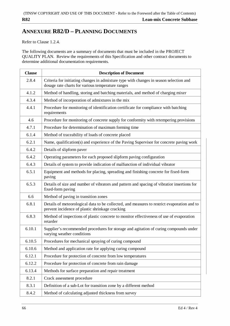
(TfNSW COPYRIGHT AND USE OF THIS DOCUMENT - Refer to the Foreword after the Table of Contents) R82 Lean-mix Concrete Subbase
66 Ed 4 / Rev 4
ANNEXURE R82/D – PLANNING DOCUMENTS Refer to Clause 1.2.4.
The following documents are a summary of documents that must be included in the PROJECT QUALITY PLAN. Review the requirements of this Specification and other contract documents to determine additional documentation requirements.
Clause Description of Document
2.8.4 Criteria for initiating changes in admixture type with changes in season selection and dosage rate charts for various temperature ranges
4.1.2 Method of handling, storing and batching materials, and method of charging mixer
4.3.4 Method of incorporation of admixtures in the mix
4.4.1 Procedure for monitoring of identification certificate for compliance with batching requirements
4.6 Procedure for monitoring of concrete supply for conformity with retempering provisions
4.7.1 Procedure for determination of maximum forming time
6.1.4 Method of traceability of loads of concrete placed
6.2.1 Name, qualification(s) and experience of the Paving Supervisor for concrete paving work
6.4.2 Details of slipform paver
6.4.2 Operating parameters for each proposed slipform paving configuration
6.4.3 Details of system to provide indication of malfunction of individual vibrator
6.5.1 Equipment and methods for placing, spreading and finishing concrete for fixed-form paving
6.5.3 Details of size and number of vibrators and pattern and spacing of vibratior insertions for fixed-form paving
6.6 Method of paving in transition zones
6.8.1 Details of meteorological data to be collected, and measures to restrict evaporation and to prevent incidence of plastic shrinkage cracking
6.8.3 Method of inspections of plastic concrete to monitor effectiveness of use of evaporation retarder
6.10.1 Supplier’s recommended procedures for storage and agitation of curing compounds under varying weather conditions
6.10.5 Procedures for mechanical spraying of curing compound
6.10.6 Method and application rate for applying curing compound
6.12.1 Procedure for protection of concrete from low temperatures
6.12.2 Procedure for protection of concrete from rain damage
6.13.4 Methods for surface preparation and repair treatment
8.2.1 Crack assessment procedure
8.3.1 Definition of a sub-Lot for transition zone by a different method
8.4.2 Method of calculating adjusted thickness from survey

(TfNSW COPYRIGHT AND USE OF THIS DOCUMENT - Refer to the Foreword after the Table of Contents) Lean-mix Concrete Subbase R82
Ed 4 / Rev 4 67
(TfNSW COPYRIGHT AND USE OF THIS DOCUMENT - Refer to the Foreword after the Table of Contents) R82 Lean-mix Concrete Subbase
68 Ed 4 / Rev 4
ANNEXURE R82/E – MIXER UNIFORMITY TESTING
E1 GENERAL
E1.1 Charging Mixer
For the purpose of conducting mixer uniformity test, charge the mixer:
(a) in accordance with the manufacturer's instructions;
(b) in the sequence proposed to be used in the Works;
(c) to the maximum volume (or throughput) proposed to be used in the Works.
Thereafter, use the same charging sequence and do not exceed the volume (or throughput) unless another uniformity test is conducted.
E1.2 Use of Concrete from Uniformity Test
Concrete from the mixer uniformity test may be incorporated into any part of the Works on the condition that all concrete from the test conforms to the other specified requirements and is placed in a discrete sub-Lot. The entire sub-Lot must be removed if the mixer fails to meet the criteria specified in Clause E2 or Clause E3.
E2 STATIONARY MIXERS
E2.1 General
Where concrete is to be produced and mixed by a stationary mixer, conduct mixer uniformity tests before paving using that mix, and thereafter upon production of each 30,000 m3 of concrete from that mixer (includes all mix types and customers), or as otherwise required in accordance with AS 1379 Clause 3.5.
Carry out the uniformity tests on each subbase mix to be placed in the Works. Alternatively, tests may be carried out on the subbase mix of lowest target slump to be placed in the Works, and the respective minimum mixing time so determined must thereafter be adopted for all LCS mixes.
For stationary batch mixers, conduct tests on 3 consecutive batches of the same mix which conform to the requirements of this Specification.
For stationary continuous mixers, conduct tests on 3 consecutive batches with each batch separated by an interval equivalent to at least 2 m3 of throughput of the same mix which conform to the requirements of this Specification. Each batch must comprise not less than 5 m3 of mix.
For each batch, report the following:
(a) mixing speed;
(b) batch volume;
(c) duration of charging;
(d) total mixing time or, for continuous mixers, the throughput rate;
(e) mixing time after the last addition of water.

(TfNSW COPYRIGHT AND USE OF THIS DOCUMENT - Refer to the Foreword after the Table of Contents) Lean-mix Concrete Subbase R82
Ed 4 / Rev 4 69
E2.2 Sampling
Discharge and sample the whole of a single batch by one of the following procedures:
(a) By discharge into a tipper truck with tray length not less than 8 m. Conduct sampling from the truck before tipping. Obtain the samples by using a shovel or scoop but exclude the top 100 mm of concrete.
(b) By discharge into a transport vehicle typical of that to be used in the Works, and then spread evenly over a length of between 6 m and 10 m onto ground which is either sealed or pre-dampened to prevent absorption of water from the mix. Conduct sampling from the ground.
In each case, sample the batch at 3 points approximately 15%, 50% and 85% along the discharged length of the mix, but not closer to either end than 10% of the length. Take a sample of approximately 50 litres from each point in accordance with AS 1012.1.
Additionally, obtain 24 grab samples on a uniform grid at 15%, 25%, 35%, 45%, 55%, 65%, 75% and 85% of the discharge length and 20%, 50% and 80% of the discharge width. Obtain sufficient material in each grab sample to cast one cylinder in accordance with TfNSW T304. Do not mix samples.
E2.3 Testing
Carry out the tests required for each property of the concrete in AS 1379 Table A1 on each of the 50 litre samples, in accordance with AS 1379 Appendix A, and as amended by this Specification.
Test each cylinder specimen from the grab samples at 7 days for mass per unit volume (MUV) and compressive strength as follows:
(a) Mass Per Unit Volume (MUV)
Determine the MUV of cylinders in accordance with AS 1012.12.2, qualified as follows:
(i) Determine “m1”, the initial mass of the specimen before dressing, in accordance with AS 1012.12.2 Clause 6(a), and in the saturated surface-dry (SSD) condition. This will require wet conditioning for 24 hours in accordance with AS 1012.12.2 Clause 6(c).
(ii) Assess the cylinder in accordance with Test Method TfNSW T368 for excessive voids. Dress and/or seal voids where required.
(iii) Determine “m2”, the immersed mass, including dressing, in accordance with AS 1012.12.2.
(iv) Determine “m3”, the SSD mass, including dressing. The dressing must be fully intact at the time of weighing.
(v) Calculate the volume and MUV in accordance with AS 1012.12.2. Round individual results for MUV to the nearest 1 kg/m3 (in contrast to AS1012.12.2 which requires rounding to the nearest 10 kg/m3).
(vi) Report the height and diameter of the cylinder, as tested.
(b) Compressive Strength
Determine the compressive strength of cylinders in accordance with AS 1012.9, except that results are to be rounded to the nearest 0.1 MPa.
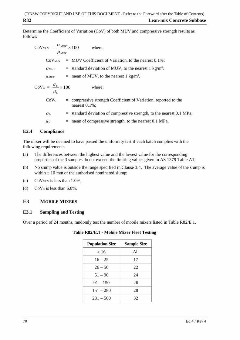
(TfNSW COPYRIGHT AND USE OF THIS DOCUMENT - Refer to the Foreword after the Table of Contents) R82 Lean-mix Concrete Subbase
70 Ed 4 / Rev 4
Determine the Coefficient of Variation (CoV) of both MUV and compressive strength results as follows:
CoVMUV = 100×MUV
MUV
µσ where:
CoVMUV = MUV Coefficient of Variation, to the nearest 0.1%;
σ MUV = standard deviation of MUV, to the nearest 1 kg/m3;
μ MUV = mean of MUV, to the nearest 1 kg/m3.
CoVC = 100×C
C
µσ where:
CoVC = compressive strength Coefficient of Variation, reported to the nearest 0.1%;
σ C = standard deviation of compressive strength, to the nearest 0.1 MPa;
μ C = mean of compressive strength, to the nearest 0.1 MPa.
E2.4 Compliance
The mixer will be deemed to have passed the uniformity test if each batch complies with the following requirements:
(a) The differences between the highest value and the lowest value for the corresponding properties of the 3 samples do not exceed the limiting values given in AS 1379 Table A1;
(b) No slump value is outside the range specified in Clause 3.4. The average value of the slump is within ± 10 mm of the authorised nominated slump;
(c) CoVMUV is less than 1.0%;
(d) CoVC is less than 6.0%.
E3 MOBILE MIXERS
E3.1 Sampling and Testing
Over a period of 24 months, randomly test the number of mobile mixers listed in Table R82/E.1.
Table R82/E.1 - Mobile Mixer Fleet Testing
Population Size Sample Size
< 16 All
16 – 25 17
26 – 50 22
51 – 90 24
91 – 150 26
151 – 280 28
281 – 500 32
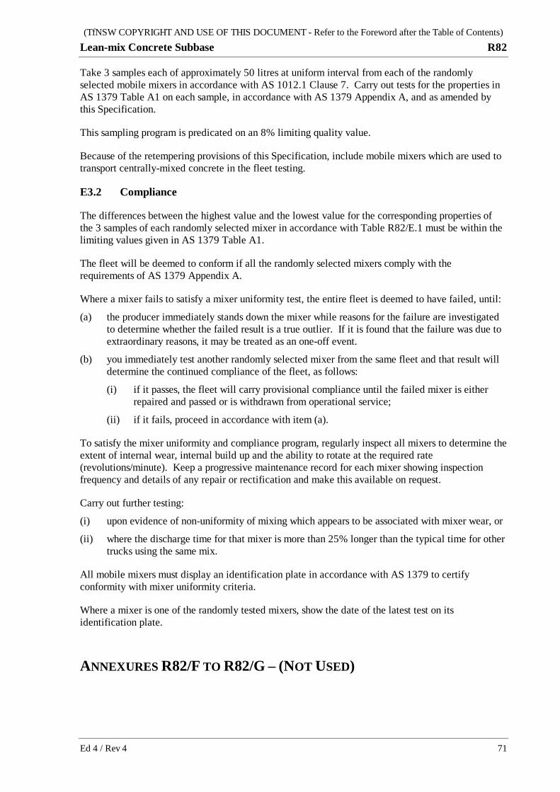
(TfNSW COPYRIGHT AND USE OF THIS DOCUMENT - Refer to the Foreword after the Table of Contents) Lean-mix Concrete Subbase R82
Ed 4 / Rev 4 71
Take 3 samples each of approximately 50 litres at uniform interval from each of the randomly selected mobile mixers in accordance with AS 1012.1 Clause 7. Carry out tests for the properties in AS 1379 Table A1 on each sample, in accordance with AS 1379 Appendix A, and as amended by this Specification.
This sampling program is predicated on an 8% limiting quality value.
Because of the retempering provisions of this Specification, include mobile mixers which are used to transport centrally-mixed concrete in the fleet testing.
E3.2 Compliance
The differences between the highest value and the lowest value for the corresponding properties of the 3 samples of each randomly selected mixer in accordance with Table R82/E.1 must be within the limiting values given in AS 1379 Table A1.
The fleet will be deemed to conform if all the randomly selected mixers comply with the requirements of AS 1379 Appendix A.
Where a mixer fails to satisfy a mixer uniformity test, the entire fleet is deemed to have failed, until:
(a) the producer immediately stands down the mixer while reasons for the failure are investigated to determine whether the failed result is a true outlier. If it is found that the failure was due to extraordinary reasons, it may be treated as an one-off event.
(b) you immediately test another randomly selected mixer from the same fleet and that result will determine the continued compliance of the fleet, as follows:
(i) if it passes, the fleet will carry provisional compliance until the failed mixer is either repaired and passed or is withdrawn from operational service;
(ii) if it fails, proceed in accordance with item (a).
To satisfy the mixer uniformity and compliance program, regularly inspect all mixers to determine the extent of internal wear, internal build up and the ability to rotate at the required rate (revolutions/minute). Keep a progressive maintenance record for each mixer showing inspection frequency and details of any repair or rectification and make this available on request.
Carry out further testing:
(i) upon evidence of non-uniformity of mixing which appears to be associated with mixer wear, or
(ii) where the discharge time for that mixer is more than 25% longer than the typical time for other trucks using the same mix.
All mobile mixers must display an identification plate in accordance with AS 1379 to certify conformity with mixer uniformity criteria.
Where a mixer is one of the randomly tested mixers, show the date of the latest test on its identification plate.
ANNEXURES R82/F TO R82/G – (NOT USED)
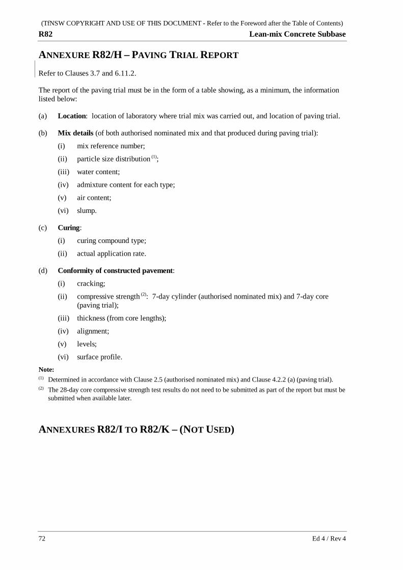
(TfNSW COPYRIGHT AND USE OF THIS DOCUMENT - Refer to the Foreword after the Table of Contents) R82 Lean-mix Concrete Subbase
72 Ed 4 / Rev 4
ANNEXURE R82/H – PAVING TRIAL REPORT Refer to Clauses 3.7 and 6.11.2.
The report of the paving trial must be in the form of a table showing, as a minimum, the information listed below:
(a) Location: location of laboratory where trial mix was carried out, and location of paving trial.
(b) Mix details (of both authorised nominated mix and that produced during paving trial):
(i) mix reference number;
(ii) particle size distribution (1);
(iii) water content;
(iv) admixture content for each type;
(v) air content;
(vi) slump.
(c) Curing:
(i) curing compound type;
(ii) actual application rate.
(d) Conformity of constructed pavement:
(i) cracking;
(ii) compressive strength (2): 7-day cylinder (authorised nominated mix) and 7-day core (paving trial);
(iii) thickness (from core lengths);
(iv) alignment;
(v) levels;
(vi) surface profile. Note: (1) Determined in accordance with Clause 2.5 (authorised nominated mix) and Clause 4.2.2 (a) (paving trial). (2) The 28-day core compressive strength test results do not need to be submitted as part of the report but must be
submitted when available later.
ANNEXURES R82/I TO R82/K – (NOT USED)
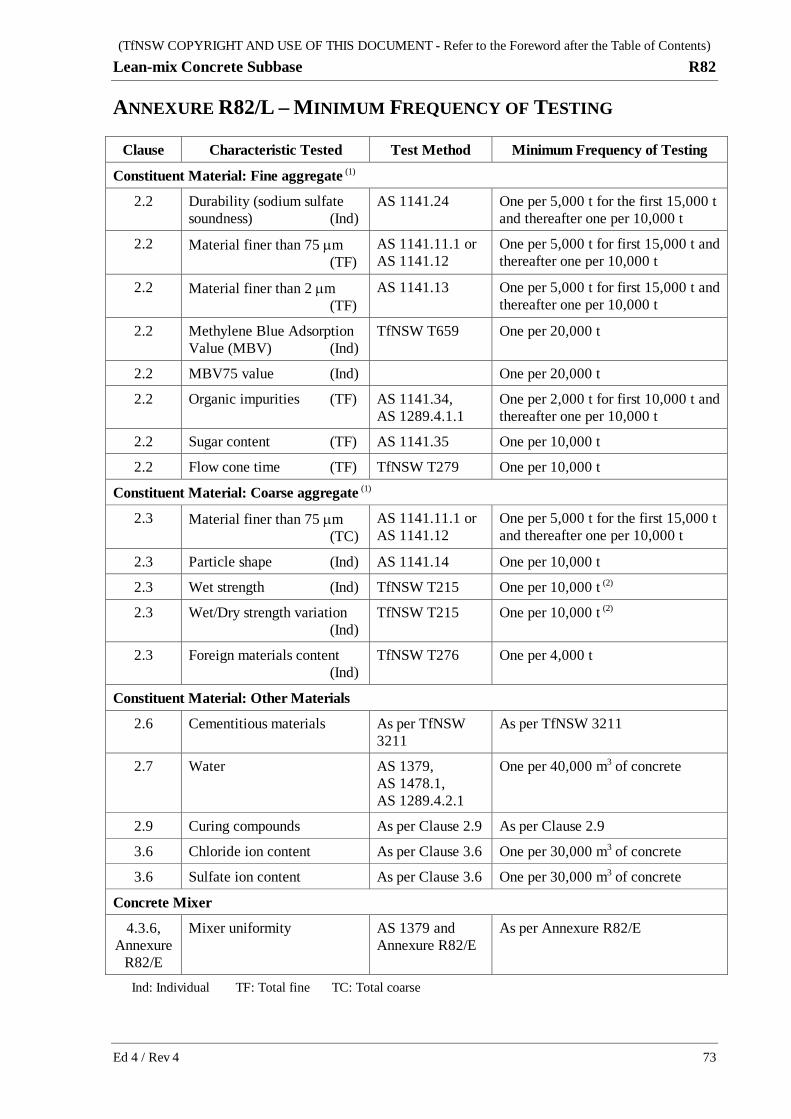
(TfNSW COPYRIGHT AND USE OF THIS DOCUMENT - Refer to the Foreword after the Table of Contents) Lean-mix Concrete Subbase R82
Ed 4 / Rev 4 73
ANNEXURE R82/L – MINIMUM FREQUENCY OF TESTING
Clause Characteristic Tested Test Method Minimum Frequency of Testing
Constituent Material: Fine aggregate (1)
2.2 Durability (sodium sulfate soundness) (Ind)
AS 1141.24 One per 5,000 t for the first 15,000 t and thereafter one per 10,000 t
2.2 Material finer than 75 µm (TF)
AS 1141.11.1 or AS 1141.12
One per 5,000 t for first 15,000 t and thereafter one per 10,000 t
2.2 Material finer than 2 µm (TF)
AS 1141.13 One per 5,000 t for first 15,000 t and thereafter one per 10,000 t
2.2 Methylene Blue Adsorption Value (MBV) (Ind)
TfNSW T659 One per 20,000 t
2.2 MBV75 value (Ind) One per 20,000 t
2.2 Organic impurities (TF) AS 1141.34, AS 1289.4.1.1
One per 2,000 t for first 10,000 t and thereafter one per 10,000 t
2.2 Sugar content (TF) AS 1141.35 One per 10,000 t
2.2 Flow cone time (TF) TfNSW T279 One per 10,000 t
Constituent Material: Coarse aggregate (1)
2.3 Material finer than 75 µm (TC)
AS 1141.11.1 or AS 1141.12
One per 5,000 t for the first 15,000 t and thereafter one per 10,000 t
2.3 Particle shape (Ind) AS 1141.14 One per 10,000 t
2.3 Wet strength (Ind) TfNSW T215 One per 10,000 t (2)
2.3 Wet/Dry strength variation (Ind)
TfNSW T215 One per 10,000 t (2)
2.3 Foreign materials content (Ind)
TfNSW T276 One per 4,000 t
Constituent Material: Other Materials
2.6 Cementitious materials As per TfNSW 3211
As per TfNSW 3211
2.7 Water AS 1379, AS 1478.1, AS 1289.4.2.1
One per 40,000 m3 of concrete
2.9 Curing compounds As per Clause 2.9 As per Clause 2.9
3.6 Chloride ion content As per Clause 3.6 One per 30,000 m3 of concrete
3.6 Sulfate ion content As per Clause 3.6 One per 30,000 m3 of concrete
Concrete Mixer
4.3.6, Annexure
R82/E
Mixer uniformity AS 1379 and Annexure R82/E
As per Annexure R82/E
Ind: Individual TF: Total fine TC: Total coarse

(TfNSW COPYRIGHT AND USE OF THIS DOCUMENT - Refer to the Foreword after the Table of Contents) R82 Lean-mix Concrete Subbase
74 Ed 4 / Rev 4
Clause Characteristic Tested Test Method Minimum Frequency of Testing
Batched Concrete
2.5 Particle size distribution of combined aggregate (3, 4, 5)
AS 1141.11.1 or TfNSW T329 (3)
One per 500 m3 for first 5,000 m3 and thereafter one per 1,500 m3 of concrete
4.2 Water content One per 5,000 m3
4.5 Concrete slump AS 1012.3.1 As per Clause 4.5
4.8 Air content of concrete AS 1012.4.2 As per Clause 4.8
Subgrade Beam Placing
5.3.3 Compressive strength of concrete subgrade beams at 7 days
As per Clause 5.3.3
As per Clause 5.3.3
Subbase Paving
6.7.2 Geometric tolerance on transverse joints
As per Clause 6.7.2
2 tests per joint
6.7.3 Geometric tolerance on longitudinal joints
As per Clause 6.7.3
Initially, and after each nonconformity: One per 10 lin m of joint until 5 conforming results are recorded, then one per 25 lin m
6.7.4 Geometric tolerance on outer edges
As per Clause 6.7.4
Initially, and after each nonconformity: One per 10 lin m of joint until 5 conforming results are recorded, then one per 25 lin m
6.10.6 Application rate of curing compound
As per Clause 6.10.6
As per Clause 6.10.6
6.12.3 Insitu compressive strength (for trafficking purposes)
Cores as per Clause 8.3.4
As per Clause 8.3.3
7.1 Surface level As per Clause 7.1 As per Clause 7.1
7.2 Alignment As per Clause 7.2 As per Clause 7.2
7.3 Surface profile As per Clause 7.3 As per Clause 7.3
8.3 Compressive strength of concrete cores at maximum 42 days
As per Clause 8.3 As per Clause 8.3
8.4 Thickness As per Clause 8.4 As per Clause 8.4
Notes: (1) Refer also notes to Table R82.1 and Table R82.2. (2) Provided that all of the 6 previous tests have met specified requirements for both wet strength and wet/dry
strength variation, and where all wet/dry variation results are < 25%, the frequency may be reduced to 1 per 15,000 t.
(3) Only the +1.18 mm fraction need be tested (see Clause 4.2.2). (4) At paving trial, use the wet-sieving method to determine the combined particle size distribution.

(TfNSW COPYRIGHT AND USE OF THIS DOCUMENT - Refer to the Foreword after the Table of Contents) Lean-mix Concrete Subbase R82
Ed 4 / Rev 4 75
(5) Where a plant produces less than 1,000 tonnes per day of fine or coarse aggregate for use under the Contract, the minimum of one test per day is required for particle size distribution.

(TfNSW COPYRIGHT AND USE OF THIS DOCUMENT - Refer to the Foreword after the Table of Contents) R82 Lean-mix Concrete Subbase
76 Ed 4 / Rev 4
ANNEXURE R82/M – REFERENCED DOCUMENTS Refer to Clause 1.2.4.
TfNSW Specifications
TfNSW G36 Environmental Protection
TfNSW G71 Construction Surveys
TfNSW Q Quality Management System
TfNSW R83 Concrete Pavement Base
TfNSW R106 Sprayed Bituminous Surfacing (with Cutback Bitumen)
TfNSW R111 Sprayed Bituminous Surfacing (with Bitumen Emulsion)
TfNSW 3151 Aggregate for Sprayed Bituminous Surfacing
TfNSW 3154 Granulated Glass Aggregate
TfNSW 3211 Cementitious Materials, Binders and Fillers
TfNSW 3253 Bitumen for Pavements
TfNSW 3254 Bitumen Emulsion
TfNSW Test Methods
TfNSW T183 Surface Deviation Using a Straightedge
TfNSW T192 Determination of the Texture Depth of Road Surfacing by the TRL Mini Texture Meter
TfNSW T215 Wet/Dry Strength Variation
TfNSW T240 Road Surface Texture Depth (Sand Patch)
TfNSW T276 Foreign Materials Content of Recycled Crushed Concrete
TfNSW T279 Flow Time and Voids Content of Fine Aggregate by Flow Cone
TfNSW T304 Moulding of Concrete Specimens for Testing in Compression, Indirect Tension and Flexure
TfNSW T321 Drying Shrinkage of 100 x 100 x 280 mm Concrete Prisms
TfNSW T329 Wet Sieving of Concrete
TfNSW T363 Accelerated Mortar Bar Test for the Assessment of Alkali-Reactivity of Aggregate
TfNSW T364 Concrete Prism Test for AAR Assessment
TfNSW T368 Dressing of Voids in Concrete Specimens and Unit Mass Adjustment for Embedded Steel
TfNSW T659 Methylene Blue Adsorption Value of Road Construction Material
TfNSW T1005 Recording the Infrared Spectrum of Materials

(TfNSW COPYRIGHT AND USE OF THIS DOCUMENT - Refer to the Foreword after the Table of Contents) Lean-mix Concrete Subbase R82
Ed 4 / Rev 4 77
Australian Standards
AS 1012 Methods of testing concrete
AS 1012.1 Sampling of concrete
AS 1012.3.1 Determination of properties related to the consistency of concrete - Slump test
AS 1012.3.3 Determination of properties related to the consistency of concrete - Vebe test
AS 1012.4.2 Determination of air content of freshly mixed concrete – Measuring reduction in air pressure in chamber above concrete
AS 1012.5 Determination of mass per unit volume of freshly mixed concrete
AS 1012.8.1 Method for making and curing concrete – Compression and indirect tensile test specimens
AS 1012.9 Compressive strength tests – Concrete, mortar and grout specimens
AS 1012.12.2 Determination of mass per unit volume of hardened concrete – Water displacement method
AS 1012.13 Determination of the drying shrinkage of concrete for samples prepared in the field or in the laboratory
AS 1012.14 Method for securing and testing cores from hardened concrete for compressive strength
AS 1012.20.1 Determination of chloride and sulfate in hardened concrete and aggregates – Nitric acid extraction method
AS 1141 Methods for sampling and testing aggregates
AS 1141.3.1 Sampling – Aggregates
AS 1141.4 Bulk density of aggregate
AS 1141.5 Particle density and water absorption of fine aggregate
AS 1141.6.1 Particle density and water absorption of coarse aggregate – Weighing-in-water method
AS 1141.6.2 Particle density and water absorption of coarse aggregate – Pycnometer method
AS 1141.11.1 Particle size distribution – Sieving method
AS 1141.12 Materials finer than 75 µm in aggregates (by washing)
AS 1141.13 Material finer than 2 micrometer
AS 1141.14 Particle shape, by proportional caliper
AS 1141.22 Wet/dry strength variation
AS 1141.24 Aggregate soundness – Evaluation by exposure to sodium sulphate solution
AS 1141.34 Organic impurities other than sugar
AS 1141.35 Sugar
AS 1289 Methods of testing soils for engineering purposes
AS 1289.4.1.1 Soil chemical tests – Determination of the organic matter content of a soil – Normal method
(TfNSW COPYRIGHT AND USE OF THIS DOCUMENT - Refer to the Foreword after the Table of Contents) R82 Lean-mix Concrete Subbase
78 Ed 4 / Rev 4
AS 1289.4.2.1 Soil chemical tests – Determination of the sulfate content of a natural soil and the sulfate content of the groundwater – Normal method
AS 1379 Specification and supply of concrete
AS 1478.1 Chemical admixtures for concrete, mortar and grout – Admixtures for concrete
AS 2341.18 Methods of testing bituminous and related roadmaking products – Determination of softening point (ring and ball method)
AS/NZS 2341.27 Methods of testing bitumen and related roadmaking products - Determination of sedimentation
AS 2350.2 Methods of testing portland, blended and masonry cements – Chemical composition
AS 2758.1 Aggregates and rock for engineering purposes – Concrete aggregates
AS 3799 Liquid membrane-forming curing compounds for concrete
AS/NZS 4671 Steel reinforcing materials
AS/NZS 4680 Hot-dip galvanized (zinc) coatings on fabricated ferrous articles
AS/NZS ISO 9001 Quality management systems – Requirements
AS ISO/IEC 17000 Conformity assessment – Vocabulary and general principles
Other Standards
ASTM C1064M Standard Test Method for Temperature of Freshly Mixed Hydraulic-Cement Concrete