IC Engine Emissions P M V Subbarao Professor Mechanical Engineering Department A Sad Story of...
33
IC Engine Emissions P M V Subbarao Professor Mechanical Engineering Department A Sad Story of Artificial Animal in Natural Environment…..
-
Upload
lucinda-cox -
Category
Documents
-
view
214 -
download
0
Transcript of IC Engine Emissions P M V Subbarao Professor Mechanical Engineering Department A Sad Story of...

IC Engine Emissions
P M V SubbaraoProfessor
Mechanical Engineering Department
A Sad Story of Artificial Animal in Natural Environment…..

Emission sources in a gasoline fuelled car
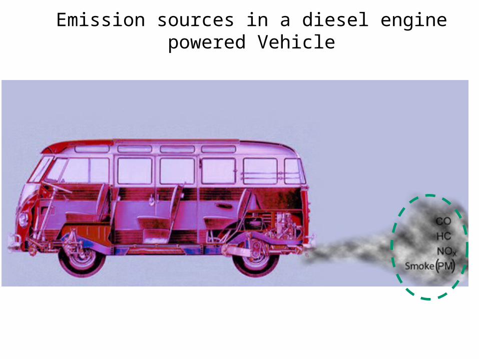
Emission sources in a diesel engine powered Vehicle

The Unreasonable Interaction with
Environment
4

Engine Development : Pleasure to Pain
• During the 1940s air pollution as a problem was first recognized in the Los Angeles basin.
• Two causes of this were the large population density and the local weather conditions.
• Smoke and other pollutants combined with fog to form smog.
• In 1966 HC and CO emission limits were introduced.
• By making more fuel efficient engines and with the use of exhaust after treatment, emissions per vehicle of HC, CO, and NOx were reduced by about 95% during the 1970s and 1980s.

Engine Emissions Vs Combustion Strategy
• Principal Engine Emissions
• SI Engines : CO, HC and NOx
• CI Engines : CO, HC, NOx and PM
6
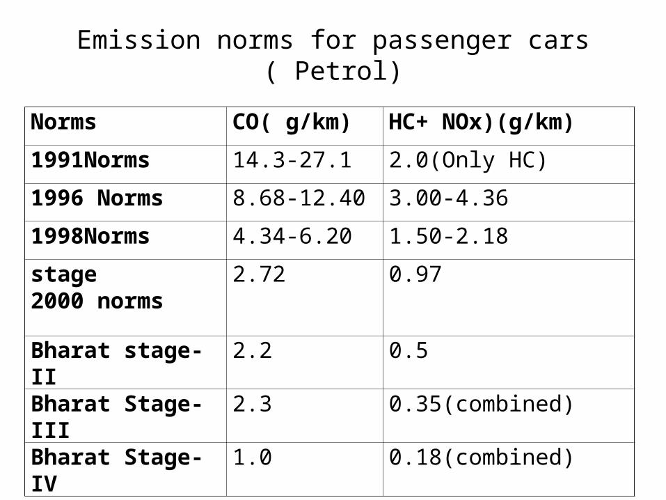
Emission norms for passenger cars ( Petrol)
Norms CO( g/km) HC+ NOx)(g/km)
1991Norms 14.3-27.1 2.0(Only HC)
1996 Norms 8.68-12.40 3.00-4.36
1998Norms 4.34-6.20 1.50-2.18
stage2000 norms
2.72 0.97
Bharat stage-II 2.2 0.5
Bharat Stage-III 2.3 0.35(combined)
Bharat Stage-IV 1.0 0.18(combined)

Emission Norms for 2/3 Wheelers ( Petrol)
Norms CO ( g/km) HC+ NOx (g/km)
1991 norms 12-30 8-12 (only HC)
1996 norms 4.5 3.6
stage 2000 norms
2.0 2.0
Bharat stage-II 1.6 1.5
Bharat Stage-III 1.0 1.0
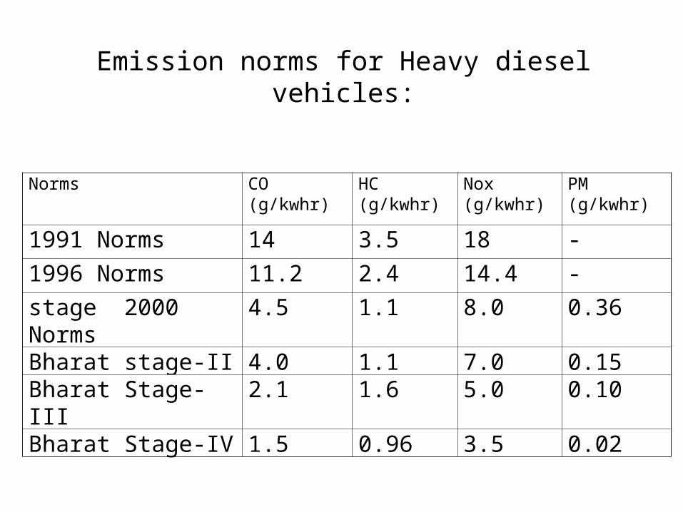
Emission norms for Heavy diesel vehicles:
Norms CO (g/kwhr)
HC(g/kwhr)
Nox(g/kwhr)
PM(g/kwhr)
1991 Norms 14 3.5 18 -
1996 Norms 11.2 2.4 14.4 -
stage 2000 Norms 4.5 1.1 8.0 0.36
Bharat stage-II 4.0 1.1 7.0 0.15Bharat Stage-III 2.1 1.6 5.0 0.10Bharat Stage-IV 1.5 0.96 3.5 0.02

The Cylinder & Hydrocarbon Emission Sources
All these collection centers accumulate air fuel mixture during compression.
They release unburnt HCs during Expansion into Cylinder.
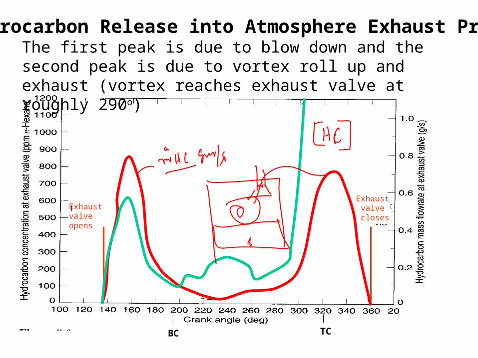
Hydrocarbon Release into Atmosphere Exhaust Process
Exhaust valve opens
Exhaust valve closes
The first peak is due to blow down and the second peak is due to vortex roll up and exhaust (vortex reaches exhaust valve at roughly 290o)
TCBC

Hydrocarbon Emission Sources for SI Engines
There are six primary Sources believed to be responsible for hydrocarbon emissions:
% fuel escaping Source normal combustion % HC emissions
Crevices 5.2 38Oil layers 1.0 16Deposits 1.0 16Liquid fuel 1.2 20Flame quench 0.5 5Exhaust valve leakage 0.1 5Total 9.0 100
RT
pxx
Tdt
HCdOHC 2
ˆˆ18735
exp107.6 15

Heat Transfer from Cylinder
cg
coolantgas
hkx
h
TT
A
11

Coolant Temperature Vs HC Emissions
14
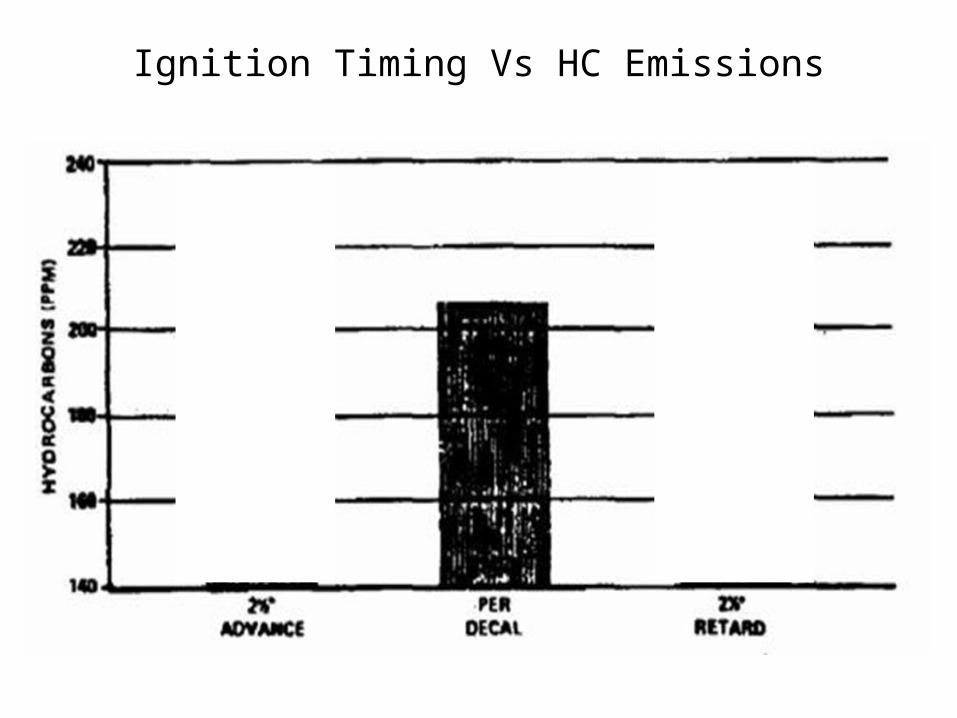
Ignition Timing Vs HC Emissions

Effect of Misfiring on HC Emissions

Hydrocarbon Emission Sources for CI Engines
Overmixing of fuel and air - During the ignition delay period evaporated fuel mixes with the air, regions of fuel-air mixture are produced that are too lean to burn.
Some of this fuel makes its way out the exhaust. Longer ignition delay more fuel becomes overmixed.Undermixing of fuel and air - Fuel leaving the injector nozzle at low
velocity, at the end of the injection process cannot completely mix with air and burn.
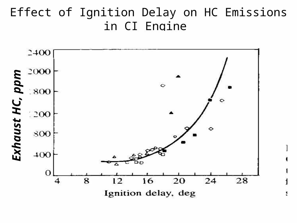
Effect of Ignition Delay on HC Emissions in CI Engine E
xhau
st H
C, p
pm

Formation of CO in IC Engines
• Formation of CO is well established.
• Locally, there may not be enough O2 available for complete oxidation and some of the carbon in the fuel ends up as CO.
• The amount of CO, for a range of fuel composition and C/H ratios, is a function of the relative air-fuel ratio.
• Even at sufficient oxygen level, high peak temperatures can cause dissociation.
• Conversion of CO to CO2 is governed by reaction
HCOOHCO 2
• Dissociated CO may freeze during the expansion stroke.
The highest CO emission occurs during engine start up (warm up) when the engine is run fuel rich to compensate for poor fuel
evaporation.
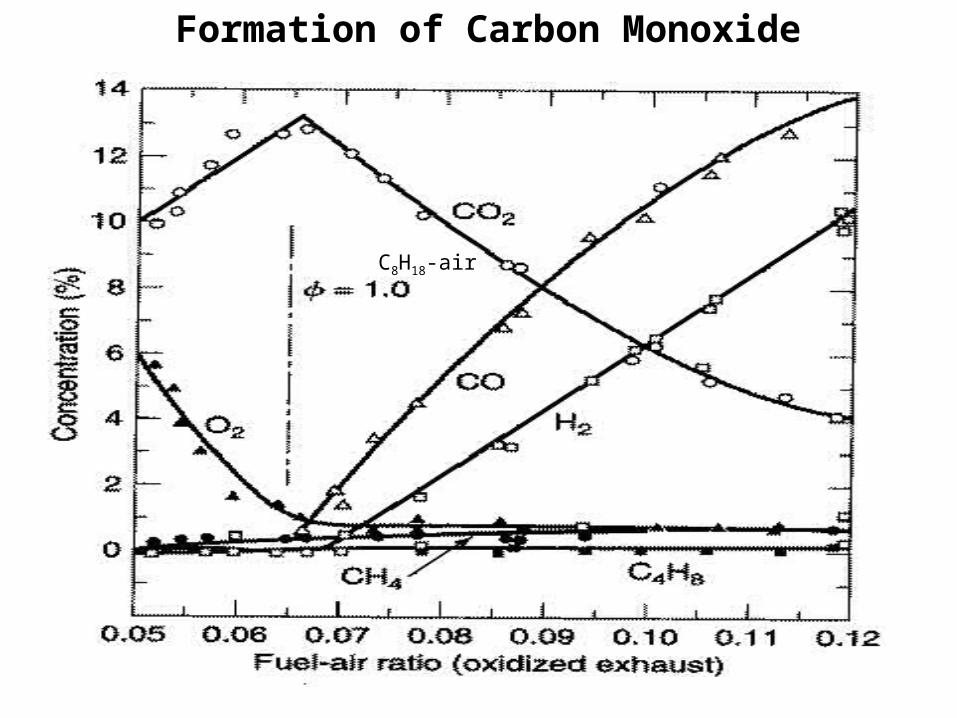
Formation of Carbon Monoxide
C8H18-air

Air/Fuel Ratio Vs Carbon Monoxide Concentration
Formation of CO in CI Engines
• The mean air-fuel mixture present in the combustion chamber per cycle is far leaner in the diesel engine than in the SI engine.
• Due to a lack of homogeneity of the mixture built up by stratification, however, extremely “rich” local zones are exist.
• This produces high CO concentrations that are reduced to a greater or lesser extent by post-oxidation.
• When the excess-air ratio increases, dropping temperatures cause the post-oxidation rate to be reduced.
• The reactions “freeze up”.
• However, the final CO concentrations of diesel engines therefore are far lower than in SI engines.
• The basic principles of CO formation, however, are the same as in SI engine.

Particulates
• A high concentration of particulate matter (PM) is manifested as visible smoke in the exhaust gases.
• Particulates are any substance other than water that can be collected by filtering the exhaust, classified as:
• Solid carbon material or soot.
• Condensed hydrocarbons and their partial oxidation products.
• Diesel particulates consist of solid carbon (soot) at exhaust gas temperatures below 500oC, HC compounds become absorbed on the surface.
• In a properly adjusted SI engines soot is not usually a problem .
• Particulate can arise if leaded fuel or overly rich fuel-air mixture are used.
• Burning crankcase oil will also produce smoke especially during engine warm up where the HC condense in the exhaust gas.

Particulate composition of diesel engine exhaust

25
The soot formation process is very fast.10 – 22 C atoms are converted into 106 C atoms in less than 1 ms.Based on equilibrium the composition of the fuel-oxidizer mixture soot , formation occurs when x ≥ 2a (or x/2a ≥ 1) in the following reaction:
Mechanism of Formation of Particulates (soot)
)()2(2
2 22 sCaxHy
aCOaOHC yx
Experimentally it is found that the critica C/O ratio for onset of soot formation is between 0.5 and 0.8.The CO, H2, and C(s) are subsequently oxidized in the diffusion flame to CO2 and H2O via the following second stage.
OHOHCOOsCCOOCO 2222222 2
1 )(
2
1
Any carbon not oxidized in the cylinder ends up as soot in the exhaust!

NOx Formation in I.C. Engines
Three chemical reactions form the Zeldovich reaction are:
Forward rate constants:
Tk
Tk
Tk
f
f
f
/450exp101.7
/4680exp108.1
/38370exp108.1
10,3
7,2
11,1
Zelodvich reaction is the most significant mechanism of NO formation in IC engines.
27
Global Reaction Rate
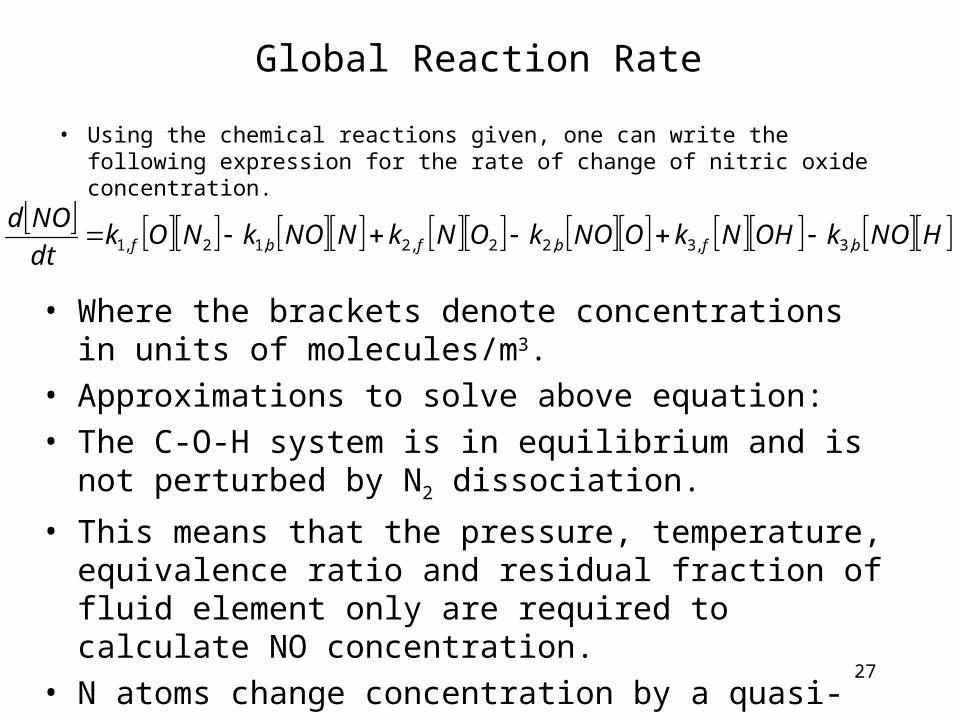
• Using the chemical reactions given, one can write the following expression for the rate of change of nitric oxide concentration.
• Where the brackets denote concentrations in units of molecules/m3.
• Approximations to solve above equation:
• The C-O-H system is in equilibrium and is not perturbed by N2 dissociation.
• This means that the pressure, temperature, equivalence ratio and residual fraction of fluid element only are required to calculate NO concentration.
• N atoms change concentration by a quasi-steady process.
• This means that one can solve for the N atom concentration by setting the rate of change of atoms to zero.
HNOkOHNkONOkONkNNOkNOkdt
NOdbfbfbf ,3,3,22,2,12,1

28

29
Effect of Equivalence Ratio on NO Concentration
Emissions Control• Three basic methods used to control engine emissions:
• 1)Engineering of combustion process -advances in fuel injectors, oxygen sensors, and on-board computers.
• 2) Optimizing the choice of operating parameters -two Nox control measures that have been used in automobile engines are spark retard and EGR.
• 3) After treatment devices in the exhaust system -catalytic converter.
30
31
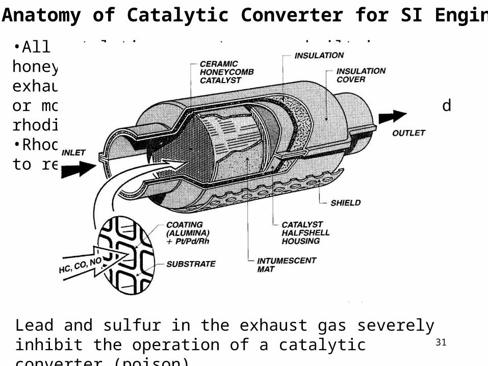
Anatomy of Catalytic Converter for SI Engines
•All catalytic converters are built in a honeycomb or pellet geometry to expose the exhaust gases to a large surface made of one or more noble metals: platinum, palladium and rhodium.•Rhodium used to remove NO and platinum used to remove HC and CO.
Lead and sulfur in the exhaust gas severely inhibit the operation of a catalytic converter (poison).

32
Three-way Catalytic Converter
•A catalyst forces a reaction at a temperature lower than normally occurs.•As the exhaust gases flow through the catalyst, the NO reacts with the CO, HC and H2 via a reduction reaction on the catalyst surface.
• NO+CO→½N2+CO2 , NO+H2 → ½N2+H2O, and others•The remaining CO and HC are removed through an oxidation reaction forming CO2 and H2O products (air added to exhaust after exhaust valve).•A three-way catalysts will function correctly only if the exhaust gas composition corresponds to nearly (±1%) stoichiometric combustion.• If the exhaust is too lean – NO is not destroyed• If the exhaust is too rich – CO and HC are not destroyed•A closed-loop control system with an oxygen sensor in the exhaust is used to A/F ratio and used to adjust the fuel injector so that the A/F ratio is near stoichiometric.

Effect of Mixture Composition